EP0584997A2 - Downhole tool operating system and method - Google Patents
Downhole tool operating system and method Download PDFInfo
- Publication number
- EP0584997A2 EP0584997A2 EP93306312A EP93306312A EP0584997A2 EP 0584997 A2 EP0584997 A2 EP 0584997A2 EP 93306312 A EP93306312 A EP 93306312A EP 93306312 A EP93306312 A EP 93306312A EP 0584997 A2 EP0584997 A2 EP 0584997A2
- Authority
- EP
- European Patent Office
- Prior art keywords
- piston
- housing
- well
- response
- pressure
- Prior art date
- Legal status (The legal status is an assumption and is not a legal conclusion. Google has not performed a legal analysis and makes no representation as to the accuracy of the status listed.)
- Granted
Links
- 238000000034 method Methods 0.000 title description 7
- 230000003213 activating effect Effects 0.000 claims abstract description 34
- 230000004044 response Effects 0.000 claims abstract description 26
- 230000006870 function Effects 0.000 claims description 8
- 230000000750 progressive effect Effects 0.000 claims description 3
- 230000015572 biosynthetic process Effects 0.000 description 37
- 238000005755 formation reaction Methods 0.000 description 37
- 239000012530 fluid Substances 0.000 description 36
- 238000012360 testing method Methods 0.000 description 33
- 239000007789 gas Substances 0.000 description 10
- 238000005553 drilling Methods 0.000 description 9
- 230000002706 hydrostatic effect Effects 0.000 description 7
- 230000001276 controlling effect Effects 0.000 description 6
- 230000008859 change Effects 0.000 description 5
- 238000004891 communication Methods 0.000 description 5
- 238000007667 floating Methods 0.000 description 5
- 238000009434 installation Methods 0.000 description 5
- IJGRMHOSHXDMSA-UHFFFAOYSA-N Atomic nitrogen Chemical compound N#N IJGRMHOSHXDMSA-UHFFFAOYSA-N 0.000 description 4
- 239000004020 conductor Substances 0.000 description 4
- 230000007246 mechanism Effects 0.000 description 4
- 230000001419 dependent effect Effects 0.000 description 3
- 230000000875 corresponding effect Effects 0.000 description 2
- 229910001873 dinitrogen Inorganic materials 0.000 description 2
- 238000004519 manufacturing process Methods 0.000 description 2
- 230000005355 Hall effect Effects 0.000 description 1
- 235000014676 Phragmites communis Nutrition 0.000 description 1
- 239000000654 additive Substances 0.000 description 1
- 238000004458 analytical method Methods 0.000 description 1
- 230000004888 barrier function Effects 0.000 description 1
- 230000002596 correlated effect Effects 0.000 description 1
- 230000001351 cycling effect Effects 0.000 description 1
- 230000007423 decrease Effects 0.000 description 1
- 230000000694 effects Effects 0.000 description 1
- 238000005516 engineering process Methods 0.000 description 1
- 239000007788 liquid Substances 0.000 description 1
- 239000000463 material Substances 0.000 description 1
- 229910052757 nitrogen Inorganic materials 0.000 description 1
- 239000003129 oil well Substances 0.000 description 1
- 230000000452 restraining effect Effects 0.000 description 1
- 230000002441 reversible effect Effects 0.000 description 1
Images
Classifications
-
- E—FIXED CONSTRUCTIONS
- E21—EARTH DRILLING; MINING
- E21B—EARTH DRILLING, e.g. DEEP DRILLING; OBTAINING OIL, GAS, WATER, SOLUBLE OR MELTABLE MATERIALS OR A SLURRY OF MINERALS FROM WELLS
- E21B41/00—Equipment or details not covered by groups E21B15/00 - E21B40/00
-
- E—FIXED CONSTRUCTIONS
- E21—EARTH DRILLING; MINING
- E21B—EARTH DRILLING, e.g. DEEP DRILLING; OBTAINING OIL, GAS, WATER, SOLUBLE OR MELTABLE MATERIALS OR A SLURRY OF MINERALS FROM WELLS
- E21B34/00—Valve arrangements for boreholes or wells
- E21B34/16—Control means therefor being outside the borehole
Definitions
- This invention relates generally to a system for operating a plurality of downhole functions, and more particularly but not exclusively to a system selectively actuating downhole tools based on the amount of pressure applied to the annulus of an oil or gas well.
- a formation tester valve and a circulation valve are devices that are used to conduct a drill stem test.
- the tester valve is repeatedly opened and closed to allow and prevent oil or gas flow from the well so that the pressure in the well can be checked under such flow and shut in conditions.
- the circulation valve is opened to allow fluid to be circulated between the surface and well.
- an apparatus can be lowered into a well on an electrically conductive cable, known as a wireline, so that electrical signals can be transferred between the surface and the apparatus down in the well.
- an apparatus can be lowered into a well as part of a pipe string along which acoustic or electromagnetic signals can be sent.
- pressure signals can be sent through fluid in a pipe string or in an annulus around the pipe string.
- a system for controlling a plurality of downhole functions which system comprises a housing; biasing means for providing a biasing force inside said housing; means for receiving into said housing an activating force so that the activating force acts in opposition to the biasing force; and computer means for operating the plurality of downhole functions in response to different magnitudes of the activating force acting in opposition to the biasing force.
- the invention provides a system and method for selectively actuating multiple downhole apparatus based on the amount of pressure applied to the annulus of an oil or gas well.
- the applied pressure causes a change in an internal volume.
- a selected apparatus is operated.
- this particular type of operation is not dependent upon time, but rather it is dependent upon volumetric change so that operation of the selected apparatus will occur as long as the required change occurs.
- the system of the present invention comprises a piston; a chamber having the piston disposed therein and further having a pressurized fluid therein on one side of the piston; means for communicating pressure from the well into the chamber on the other side of the piston so that communicated pressure greater than the pressure of the pressurized fluid in the chamber moves the piston in the chamber, the piston being moved to different positions in the chamber in response to different magnitudes of communicated pressure; piston position detecting means, connected to the chamber, for detecting the piston at respective positions in the chamber; and means, connected to the piston position detecting means, for operating at least a respective one of the apparatus for each respective position of the piston detected by the piston position detecting means.
- the present invention also provides a method for controlling a plurality of downhole apparatus, comprising: providing a biasing force in a well; receiving an activating force so that the activating force acts in opposition to the biasing force in the well; and selectively operating in the well the plurality of downhole apparatus in response to different magnitudes of the activating force acting in opposition to the biasing force.
- the present invention provides a method for controlling a plurality of apparatus for performing respective functions in a well, comprising: lowering a tool string into the well, the tool string including the plurality of apparatus; increasing pressure in the well to a first magnitude; moving a member to a first position in the tool string in response to the pressure at the first magnitude acting against the member and a pressurized fluid in the tool string; sensing when the member has moved to the first position and in response generating a control signal for a first respective one of the apparatus; increasing pressure in the well to a second magnitude; moving the member to a second position in the tool string in response to the pressure at the second magnitude acting against the member and the pressurized fluid in the tool string; and sensing when the member has moved to the second position and in response generating a control signal for a second respective one of the apparatus.
- the member is a piston disposed for progressive linear movement within the tool string and the pressure is pressure in an annulus defined in the well outside the tool string.
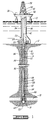
- FIG. 1 is a schematic elevational view of a well test string in which the present invention can be used.
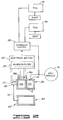
- FIG. 2 is a schematic illustration of one embodiment of system of the present invention adapted to control two downhole tools.
- drilling fluid a fluid known as drilling fluid or drilling mud.
- drilling fluid a fluid known as drilling fluid or drilling mud.
- drilling fluid One of the purposes of this drilling fluid is to contain in intersected formations any formation fluid which may be found there.
- the drilling mud is weighted with various additives so that the hydrostatic pressure of the mud at the formation depth is sufficient to maintain the formation fluid within the formation without allowing it to escape into the borehole.
- Drilling fluids and formation fluids can all be generally referred to as well fluids.
- testing string When it is desired to test the production capabilities of the formation, a string of interconnected pipe sections and downhole tools referred to as a testing string is lowered into the borehole to the formation depth and the formation fluid is allowed to flow into the string in a controlled testing program.
- lower pressure is maintained in the interior of the testing string as it is lowered into the borehole. This is usually done by keeping a formation tester valve in the closed position near the lower end of the testing string. When the testing depth is reached, a packer is set to seal the borehole, thus closing the formation from the hydrostatic pressure of the drilling fluid in the well annulus above the packer. The formation tester valve at the lower end of the testing string is then opened and the formation fluid, free from the restraining pressure of the drilling fluid, can flow into the interior of the testing string.
- the conditions are such that it is desirable to fill the testing string above the formation tester valve with liquid as the testing string is lowered into the well.
- This may be for the purpose of equalizing the hydrostatic pressure head across the walls of the test string to prevent inward collapse of the pipe and/or this may be for the purpose of permitting pressure testing of the test string as it is lowered into the well.
- the well testing program includes intervals of formation flow and intervals when the formation is closed in. Pressure recordings are taken throughout the program for later analysis to determine the production capability of the formation. If desired, a sample of the formation fluid may be caught in a suitable sample chamber.
- a circulation valve in the test string is opened, formation fluid in the testing string is circulated out, the packer is released, and the testing string is withdrawn.
- FIG. 1 A typical arrangement for conducting a drill stem test offshore is shown in FIG. 1.
- the present invention may also be used on wells located on shore and in other applications with other types of tools.
- the arrangement of the offshore system includes a floating work station 10 stationed over a submerged well site 12.
- the well comprises a well bore 14, which typically but not necessarily is lined with a casing string 16 extending from the submerged well site 12 to a subterranean formation 18.
- the casing string 16 includes a plurality of perforations 19 at its lower end. These provide communication between the formation 18 and a lower interior zone or annulus 20 of the well bore 14.
- a marine conductor 24 extends from the well head installation 22 to the floating work station 10.
- the floating work station 10 includes a work deck 26 which supports a derrick 28.
- the derrick 28 supports a hoisting means 30.
- a well head closure 32 is provided at the upper end of the marine conductor 24.
- the well head closure 32 allows for lowering into the marine conductor 24 and into the well bore 14 a formation testing string 34 which is raised and lowered in the well by the hoisting means 30.
- the testing string 34 may also generally be referred to as a tubing string or a tool string.
- a supply conductor 36 is provided which extends from a hydraulic pump 38 on the deck 26 of the floating station 10 and extends to the well head installation 22 at a point below the blowout preventer 23 to allow the pressurizing of a well annulus 40 defined between the testing string 34 and the well bore 14 or the casing 16 if present.
- the testing string 34 includes an upper conduit string portion 42 extending from the work deck 26 to the well head installation 22.
- a subsea test tree 44 is located at the lower end of the upper conduit string 42 and is landed in the well head installation 22.
- the lower portion of the formation testing string 34 extends from the test tree 44 to the formation 18.
- a packer mechanism 46 isolates the formation 18 from the fluids in the well annulus 40.
- an interior or tubing string bore of the tubing string 34 is isolated from the upper well annulus 40 above packer 46 unless other communication openings are provided.
- the upper well annulus 40 above packer 46 is isolated from the lower well zone 20 which is often referred to as the rat hole 20.
- a perforated tail piece 48 provided at the lower end of the testing string 34 allows fluid communication between the formation 18 and the interior of the tubular formation testing string 34.
- the lower portion of the formation testing string 34 further includes intermediate conduit portion 50 and a torque transmitting pressure and volume balanced slip joint means 52.
- An intermediate conduit portion 54 is provided for imparting packer setting weight to the packer mechanism 46 at the lower end of the string.
- a circulation valve 56 It is many times desirable to place near the lower end of the testing string 34 a circulation valve 56. Below circulating valve 56 there may be located a combination sampler valve section and reverse circulation valve 58.
- a formation tester valve 60 Also near the lower end of the formation testing string 34 is located a formation tester valve 60. Immediately above the formation testing valve 60 there may be located a drill pipe tester valve 62.
- a pressure recording device 64 is located below the formation tester valve 60.
- the pressure recording device 64 is preferably one which provides a full opening passageway through the center of the pressure recorder to provide a full opening passageway through the entire length of the formation testing string.
- the preferred embodiment system of the present invention can, for example, be carried as part of the formation testing string 34 illustrated in FIG. 1.
- the system can control the plurality of functional tools that are included in the string 34 (e.g., the circulation valve 58, the formation tester valve 60, etc.).
- the present invention can also be used in other applications and with other apparatus.
- "Apparatus” as used herein and in the claims includes any type of circuit or device or part thereof that can be operated by the present invention; this includes without limitation electrical downhole tools, mechanical downhole tools, and parts thereof known in the art.
- the system of the present invention has a pressurized fluid section 102.
- This section includes a container 104 of pressurized fluid (e.g. nitrogen gas) that acts as a biasing means for providing a biasing force inside a housing 106 that forms part of a positioning section 108 of the system.
- the fluid-charged interior of the container 104 is in communication with the interior of the housing 106 as schematically indicated by conduit 110 in FIG. 2.
- the pressurized fluid inside the housing 106 acts as a variable spring while controlling the movement of a piston 112 also inside the housing 106.
- the pressurized fluid and positioning sections 102, 108 can be made as discrete components as represented in FIG. 2, but more likely they would be integrally constructed within their own or another downhole tool.
- such a tool could include an outer case with a center mandrel through it.
- a floating piston would be located on one end of the mandrel, sealingly engaging both the mandrel and the outer case to act as a barrier between annulus fluid communicated into the case and nitrogen held in the case on the other side of the piston.
- the housing 106 provides a chamber 114 having the piston 112 disposed therein so that the piston 112 divides the chamber 114 into two variable size chamber portions or volumes 114a, 114b.
- Chamber volume 114a receives pressurized fluid from the source container 104 on one side of the piston 112.
- Chamber volume 114b receives into the housing 106 an activating force so that the activating force acts in opposition to the biasing force as defined by the pressurized gas in chamber volume 114a.
- the activating force is increased pressure in an annulus 116 of a well where the present invention is used (in the FIG. 1 environment, this would be the annulus 40).
- the piston 112 is moved to different positions in the chamber 114 in response to different magnitudes of communicated activating pressure. That is, the piston 112 moves in response to a differential between the activating force in chamber volume 114b and the biasing force in chamber volume 114a.
- each of the different magnitudes of the activating force acting in the chamber volume 114b is greater than the biasing force that exists in the chamber volume 114a at the time the respective magnitude of activating force first acts in opposition to the biasing force.
- the chamber volume 114a decreases so that the pressure in the chamber volume 114a increases.
- the system is designed so that the pressure increases until it equals the activating force of the applied annulus pressure whereupon the piston 112 stops moving.
- the position at which the piston stops should be one at which the piston position is or will have been sensed as further explained hereinbelow.
- the different magnitudes of activating force are applied at different times in the preferred embodiment.
- the system of the present invention includes an electronic section 120.
- the electronic section 120 provides means for selectively operating the plurality of downhole apparatus, such as downhole tools 122, 124 depicted in FIG. 2, in response to different magnitudes of the activating force acting against the biasing force.
- a respective control signal for a respective apparatus is generated in response to a respective magnitude of annulus pressure that provides the activating force acting against the biasing force exerted by the pressurized fluid from the container 104.
- piston position detecting means connected to the housing 106, for detecting the piston 112 at respective positions in the chamber 114.
- this means includes a plurality of switches 126 (two switches 126a, 126b shown in FIG. 2 to correspond to the two controlled downhole tools 122, 124, but more can be used and controlled).
- the switches 126 are disposed relative to the piston 112 so that the switches 126 are respectively operated in response to the piston 112 moving to different respective positions.
- each of the switches 126 is connected to the housing 106 at a respective location along the linear path of movement of the piston 112 through the chamber 114. Such locations need not be linearly aligned.
- the switches can be any suitable mechanism sensitive to where the piston 112 is inside the housing 106, such as magnetically or mechanically responsive proximity switches (preferably Hall Effect switches, but also magnetic reed switches or mechanical microswitches as other non-limiting examples).
- an acoustic range finder device 127 also represented in FIG. 2 would be used instead of the switches 126a, 126b. With this device the electronic section 120 would be set up to operate a given apparatus when the piston 112 has moved a predetermined amount as determined by the acoustic signals sent out by device 127 and returned thereto. It is contemplated that the technology of conventional devices such as used for indicating tank levels and fluid depths (e.g., depth finders for fishing boats) can be adapted for implementing the device 127 of the present invention.
- the means for selectively operating the downhole apparatus also includes means, connected to the switches 126 (or other change sensing devices), for operating at least a respective one of the apparatus for each respective position of the piston 112 detected by the switches 126.
- This is implemented using a computer connected to receive inputs in response to the switches 126 and to provide outputs for controlling the plurality of apparatus, each of the outputs corresponding to a respective one of the inputs so that each switch 126 is related to a respective apparatus.
- this computer responds to different magnitudes of the activating force acting against the biasing force.
- the computer is preferably implemented with a microcomputer 128 that receives inputs from the switches 126.
- the microcomputer 128 is programmed to react to the number of position switches that have been activated.
- the microcomputer 128 can be implemented by any suitable microprocessor, memory and ancillary devices and circuits known in the art.
- An example of suitable components that can be adapted for use in the present invention are shown in U.S. Patent 4,866,607 to Anderson et al., incorporated herein by reference. See also, for example, U.S. Patent 4,971,160 to Upchurch, incorporated herein by reference.
- the electronic section 120 also includes the power supply and ancillary circuitry as needed to operate a hydraulic control circuit 130 by which annulus fluid/pressure is diverted to operate the tools 122, 124 in a known manner. That is, under control of the microcomputer 128, the hydraulic control circuit 130 directs the porting of pressure from the well annulus 116 into the operating circuit of the tool to be controlled. While hydrostatic and applied pressure is ported to one side of the operating circuit of an apparatus, the other side of the operating circuit is ported to a region of lower pressure. This region of lower pressure can be an atmospheric dump chamber, as illustrated in FIG. 2, or a pressurized fluid (e.g., nitrogen gas) chamber that is at a lower pressure, such as in the Halliburton Services LPR-N Tester Valve.
- a pressurized fluid e.g., nitrogen gas
- the pressurized fluid section 102 is charged at the surface to a predetermined pressure dependent upon downhole temperature and pressure. This is for use in providing a biasing force in the well once the system is lowered into the well.
- the biasing force is pressurized gas having a magnitude at least equal to a hydrostatic pressure at the location in the well where the system is to be used and the method of the present invention is to be performed.
- the pressurized gas source can be hooked to a metering section that will balance the gas pressure with hydrostatic pressure. This will fix the positioning piston 112 in its initial relation to the position switches 126.
- a selected increased pressure level is applied from the surface to the well annulus 116 (annulus 40 in FIG. 1).
- This pressure is received as an activating force in the housing 106 so that the activating force acts in opposition to the biasing force exerted in the chamber volume 114a by the pressurized fluid from the container 104.
- the piston 112 begins to move within the chamber 114, thereby enlarging the volume 114b and reducing the volume 114a.
- the switches 126 are disposed and the housing 106 and piston 112 are constructed so that the piston 112 reaches the first switch 126a in response to a first predetermined pressure level or magnitude being reached in the well annulus 116.
- the piston 112 linearly moves progressively to different positions in the well (i.e., specifically, in the housing 106) in response to different magnitudes of the activating force acting in opposition to the biasing force.
- the switch is actuated so that a signal is provided to the microcomputer 128.
- the microcomputer 128 generates a signal to operate the hydraulic control circuit 130 so that the selected respective tool 122 or 124 that is correlated to the switch 126a is activated. If a higher pressure level is applied to the well annulus 116 so that the piston 112 is moved to actuate the switch 126b, then the microcomputer 128 responds by operating the hydraulic control circuit 130 to control the other of the tools 122, 124.
- the method of the present invention also comprises selectively operating in the well the plurality of downhole apparatus in response to different magnitudes of the activating force acting in opposition to the biasing force.
- Such operating includes: sensing the piston 112 reaching different positions in the housing 106; and generating a respective control signal for a respective apparatus in response to sensing the piston 112 at a respective location. This can also be accomplished using the preferred acoustic range finder 127 to generate signals indicating where the piston 112 is.
- the microcomputer 128 preferably responds either to relatively slow sequentially distinct actuations of the switches 126 (as just described) or to rapid movement of the piston 112 past one or more switches 126 to another of the switches.
- the pressure in the well annulus 116 would be incrementally increased such as, for example, to 1000 psi, then later to 1500 psi, etc., with each incremental increase moving the piston 112 to the next switch 126 location.
- the microcomputer 128 would, in this.case, respond to each switch operation individually as described above. As to the latter, a lower predetermined pressure level would be rapidly passed.
- the microcomputer 128 can be programmed to either control both tools 122, 124 (because both switches would be actuated as the piston 112 moves past the switch 126a and arrives at or past the switch 126b) or only tool 124 (assuming it is the one corresponding to switch 126b). Control of only tool 124 can be implemented by programming the microcomputer 128 to detect the time difference between receiving inputs from the switches 126. If the time between two switches being actuated is less than a predetermined minimum, the microcomputer would assume that only a pressure level selecting the last switch had been applied.
- the preferred embodiments of the present invention can be implemented using known types of materials and components suitable for use in the well environments where particular applications are to occur.
Abstract
Description
- This invention relates generally to a system for operating a plurality of downhole functions, and more particularly but not exclusively to a system selectively actuating downhole tools based on the amount of pressure applied to the annulus of an oil or gas well.
- During the drilling, completing and producing of an oil or gas well, various apparatus typically need to be lowered into the well for one purpose or another. For example, a formation tester valve and a circulation valve are devices that are used to conduct a drill stem test. The tester valve is repeatedly opened and closed to allow and prevent oil or gas flow from the well so that the pressure in the well can be checked under such flow and shut in conditions. After the desired cycling of the tester valve has been completed, the circulation valve is opened to allow fluid to be circulated between the surface and well.
- Typically such downhole apparatus do not need to be operated until they are at a desired depth in the well. Thus, there is the need for some way to operate such apparatus when they are down in the well. Although such apparatus can be automatically self-controlled so that they perform desired operations at predetermined times, many such apparatus need to perform their functions at times that cannot be predetermined. For these apparatus, there needs to be some way of communicating from the surface a command signal that will initiate or otherwise effect operation of the apparatus.
- This need for surface to downhole communication has been well recognized in the oil and gas industry, and many techniques have been developed. For example, an apparatus can be lowered into a well on an electrically conductive cable, known as a wireline, so that electrical signals can be transferred between the surface and the apparatus down in the well. As other examples, an apparatus can be lowered into a well as part of a pipe string along which acoustic or electromagnetic signals can be sent. As a further example, pressure signals can be sent through fluid in a pipe string or in an annulus around the pipe string. A specific example of a downhole tool that responds to external annulus pressure and internal pressurized gas is shown in U.S. Patents 4,633,952 and 4,711,305 to Ringgenberg.
- We have now devised an improved system for controlling operation of downhole apparatus.
- According to the present invention, there is provided a system for controlling a plurality of downhole functions which system comprises a housing; biasing means for providing a biasing force inside said housing; means for receiving into said housing an activating force so that the activating force acts in opposition to the biasing force; and computer means for operating the plurality of downhole functions in response to different magnitudes of the activating force acting in opposition to the biasing force.
- In a particular application, the invention provides a system and method for selectively actuating multiple downhole apparatus based on the amount of pressure applied to the annulus of an oil or gas well. In a particular implementation of such application, the applied pressure causes a change in an internal volume. When a sufficient change occurs, a selected apparatus is operated. Thus, this particular type of operation is not dependent upon time, but rather it is dependent upon volumetric change so that operation of the selected apparatus will occur as long as the required change occurs.
- In a particular embodiment, the system of the present invention comprises a piston; a chamber having the piston disposed therein and further having a pressurized fluid therein on one side of the piston; means for communicating pressure from the well into the chamber on the other side of the piston so that communicated pressure greater than the pressure of the pressurized fluid in the chamber moves the piston in the chamber, the piston being moved to different positions in the chamber in response to different magnitudes of communicated pressure; piston position detecting means, connected to the chamber, for detecting the piston at respective positions in the chamber; and means, connected to the piston position detecting means, for operating at least a respective one of the apparatus for each respective position of the piston detected by the piston position detecting means.
- The present invention also provides a method for controlling a plurality of downhole apparatus, comprising: providing a biasing force in a well; receiving an activating force so that the activating force acts in opposition to the biasing force in the well; and selectively operating in the well the plurality of downhole apparatus in response to different magnitudes of the activating force acting in opposition to the biasing force.
- In a particular implementation, the present invention provides a method for controlling a plurality of apparatus for performing respective functions in a well, comprising: lowering a tool string into the well, the tool string including the plurality of apparatus; increasing pressure in the well to a first magnitude; moving a member to a first position in the tool string in response to the pressure at the first magnitude acting against the member and a pressurized fluid in the tool string; sensing when the member has moved to the first position and in response generating a control signal for a first respective one of the apparatus; increasing pressure in the well to a second magnitude; moving the member to a second position in the tool string in response to the pressure at the second magnitude acting against the member and the pressurized fluid in the tool string; and sensing when the member has moved to the second position and in response generating a control signal for a second respective one of the apparatus. More particularly, the member is a piston disposed for progressive linear movement within the tool string and the pressure is pressure in an annulus defined in the well outside the tool string.
- In order that the invention may be more fully understood, reference is made to the accompanying drawings, in which:
- FIG. 1 is a schematic elevational view of a well test string in which the present invention can be used.
- FIG. 2 is a schematic illustration of one embodiment of system of the present invention adapted to control two downhole tools.
- Before the present invention is further described, a description of one environment in which the present invention can be used will be given. This example is not to be limiting as to the nature of the present invention or its applications.
- During the course of drilling an oil well, the borehole is filled with a fluid known as drilling fluid or drilling mud. One of the purposes of this drilling fluid is to contain in intersected formations any formation fluid which may be found there. To contain these formation fluids the drilling mud is weighted with various additives so that the hydrostatic pressure of the mud at the formation depth is sufficient to maintain the formation fluid within the formation without allowing it to escape into the borehole. Drilling fluids and formation fluids can all be generally referred to as well fluids.
- When it is desired to test the production capabilities of the formation, a string of interconnected pipe sections and downhole tools referred to as a testing string is lowered into the borehole to the formation depth and the formation fluid is allowed to flow into the string in a controlled testing program.
- Sometimes, lower pressure is maintained in the interior of the testing string as it is lowered into the borehole. This is usually done by keeping a formation tester valve in the closed position near the lower end of the testing string. When the testing depth is reached, a packer is set to seal the borehole, thus closing the formation from the hydrostatic pressure of the drilling fluid in the well annulus above the packer. The formation tester valve at the lower end of the testing string is then opened and the formation fluid, free from the restraining pressure of the drilling fluid, can flow into the interior of the testing string.
- At other times the conditions are such that it is desirable to fill the testing string above the formation tester valve with liquid as the testing string is lowered into the well. This may be for the purpose of equalizing the hydrostatic pressure head across the walls of the test string to prevent inward collapse of the pipe and/or this may be for the purpose of permitting pressure testing of the test string as it is lowered into the well.
- The well testing program includes intervals of formation flow and intervals when the formation is closed in. Pressure recordings are taken throughout the program for later analysis to determine the production capability of the formation. If desired, a sample of the formation fluid may be caught in a suitable sample chamber.
- At the end of the well testing program, a circulation valve in the test string is opened, formation fluid in the testing string is circulated out, the packer is released, and the testing string is withdrawn.
- A typical arrangement for conducting a drill stem test offshore is shown in FIG. 1. Of course, the present invention may also be used on wells located on shore and in other applications with other types of tools.
- The arrangement of the offshore system includes a
floating work station 10 stationed over a submergedwell site 12. The well comprises awell bore 14, which typically but not necessarily is lined with acasing string 16 extending from the submergedwell site 12 to asubterranean formation 18. - The
casing string 16 includes a plurality ofperforations 19 at its lower end. These provide communication between theformation 18 and a lower interior zone orannulus 20 of the well bore 14. - At the submerged
well site 12 is located the wellhead installation 22 which includes blowout preventer mechanisms 23. Amarine conductor 24 extends from the wellhead installation 22 to thefloating work station 10. Thefloating work station 10 includes awork deck 26 which supports aderrick 28. Thederrick 28 supports a hoisting means 30. A wellhead closure 32 is provided at the upper end of themarine conductor 24. The wellhead closure 32 allows for lowering into themarine conductor 24 and into the well bore 14 aformation testing string 34 which is raised and lowered in the well by thehoisting means 30. Thetesting string 34 may also generally be referred to as a tubing string or a tool string. - A
supply conductor 36 is provided which extends from ahydraulic pump 38 on thedeck 26 of thefloating station 10 and extends to the wellhead installation 22 at a point below the blowout preventer 23 to allow the pressurizing of a wellannulus 40 defined between thetesting string 34 and the well bore 14 or thecasing 16 if present. - The
testing string 34 includes an upperconduit string portion 42 extending from thework deck 26 to the wellhead installation 22. Asubsea test tree 44 is located at the lower end of theupper conduit string 42 and is landed in the wellhead installation 22. - The lower portion of the
formation testing string 34 extends from thetest tree 44 to theformation 18. A packer mechanism 46 isolates theformation 18 from the fluids in thewell annulus 40. Thus, an interior or tubing string bore of thetubing string 34 is isolated from theupper well annulus 40 above packer 46 unless other communication openings are provided. Also, theupper well annulus 40 above packer 46 is isolated from thelower well zone 20 which is often referred to as therat hole 20. - A
perforated tail piece 48 provided at the lower end of thetesting string 34 allows fluid communication between theformation 18 and the interior of the tubularformation testing string 34. - The lower portion of the
formation testing string 34 further includesintermediate conduit portion 50 and a torque transmitting pressure and volume balanced slip joint means 52. Anintermediate conduit portion 54 is provided for imparting packer setting weight to the packer mechanism 46 at the lower end of the string. - It is many times desirable to place near the lower end of the testing string 34 a
circulation valve 56. Below circulatingvalve 56 there may be located a combination sampler valve section andreverse circulation valve 58. - Also near the lower end of the
formation testing string 34 is located aformation tester valve 60. Immediately above theformation testing valve 60 there may be located a drillpipe tester valve 62. - A
pressure recording device 64 is located below theformation tester valve 60. Thepressure recording device 64 is preferably one which provides a full opening passageway through the center of the pressure recorder to provide a full opening passageway through the entire length of the formation testing string. - The preferred embodiment system of the present invention can, for example, be carried as part of the
formation testing string 34 illustrated in FIG. 1. The system can control the plurality of functional tools that are included in the string 34 (e.g., thecirculation valve 58, theformation tester valve 60, etc.). The present invention can also be used in other applications and with other apparatus. "Apparatus" as used herein and in the claims includes any type of circuit or device or part thereof that can be operated by the present invention; this includes without limitation electrical downhole tools, mechanical downhole tools, and parts thereof known in the art. - Referring to FIG. 2, the system of the present invention has a pressurized
fluid section 102. This section includes acontainer 104 of pressurized fluid (e.g. nitrogen gas) that acts as a biasing means for providing a biasing force inside ahousing 106 that forms part of apositioning section 108 of the system. The fluid-charged interior of thecontainer 104 is in communication with the interior of thehousing 106 as schematically indicated byconduit 110 in FIG. 2. The pressurized fluid inside thehousing 106 acts as a variable spring while controlling the movement of apiston 112 also inside thehousing 106. The pressurized fluid andpositioning sections - Further as to the
positioning section 108, thehousing 106 provides a chamber 114 having thepiston 112 disposed therein so that thepiston 112 divides the chamber 114 into two variable size chamber portions or volumes 114a, 114b. Chamber volume 114a receives pressurized fluid from thesource container 104 on one side of thepiston 112. Chamber volume 114b receives into thehousing 106 an activating force so that the activating force acts in opposition to the biasing force as defined by the pressurized gas in chamber volume 114a. In the preferred embodiment, the activating force is increased pressure in anannulus 116 of a well where the present invention is used (in the FIG. 1 environment, this would be the annulus 40). - The activating pressure communicated into the chamber volume 114b through suitable means, such as including a
port 118 of thehousing 106, acts on thepiston 112 so that communicated activating pressure greater than the fluid pressure in the chamber volume 114a moves thepiston 112 linearly in the chamber 114. Thepiston 112 is moved to different positions in the chamber 114 in response to different magnitudes of communicated activating pressure. That is, thepiston 112 moves in response to a differential between the activating force in chamber volume 114b and the biasing force in chamber volume 114a. In the preferred embodiment, each of the different magnitudes of the activating force acting in the chamber volume 114b is greater than the biasing force that exists in the chamber volume 114a at the time the respective magnitude of activating force first acts in opposition to the biasing force. As thepiston 112 moves, however, the chamber volume 114a decreases so that the pressure in the chamber volume 114a increases. The system is designed so that the pressure increases until it equals the activating force of the applied annulus pressure whereupon thepiston 112 stops moving. The position at which the piston stops should be one at which the piston position is or will have been sensed as further explained hereinbelow. The different magnitudes of activating force are applied at different times in the preferred embodiment. - To respond to movement of the
piston 112, the system of the present invention includes anelectronic section 120. Theelectronic section 120 provides means for selectively operating the plurality of downhole apparatus, such asdownhole tools container 104. These signals are generated as a result of the progressive linear movement of thepiston 112 in thehousing 106. - These movements are detected by piston position detecting means, connected to the
housing 106, for detecting thepiston 112 at respective positions in the chamber 114. In one embodiment, this means includes a plurality of switches 126 (two switches 126a, 126b shown in FIG. 2 to correspond to the two controlleddownhole tools piston 112 so that the switches 126 are respectively operated in response to thepiston 112 moving to different respective positions. In the illustrated embodiment, each of the switches 126 is connected to thehousing 106 at a respective location along the linear path of movement of thepiston 112 through the chamber 114. Such locations need not be linearly aligned. The switches can be any suitable mechanism sensitive to where thepiston 112 is inside thehousing 106, such as magnetically or mechanically responsive proximity switches (preferably Hall Effect switches, but also magnetic reed switches or mechanical microswitches as other non-limiting examples). - In another, more preferred embodiment, an acoustic
range finder device 127 also represented in FIG. 2 would be used instead of the switches 126a, 126b. With this device theelectronic section 120 would be set up to operate a given apparatus when thepiston 112 has moved a predetermined amount as determined by the acoustic signals sent out bydevice 127 and returned thereto. It is contemplated that the technology of conventional devices such as used for indicating tank levels and fluid depths (e.g., depth finders for fishing boats) can be adapted for implementing thedevice 127 of the present invention. - The means for selectively operating the downhole apparatus also includes means, connected to the switches 126 (or other change sensing devices), for operating at least a respective one of the apparatus for each respective position of the
piston 112 detected by the switches 126. This is implemented using a computer connected to receive inputs in response to the switches 126 and to provide outputs for controlling the plurality of apparatus, each of the outputs corresponding to a respective one of the inputs so that each switch 126 is related to a respective apparatus. Thus, this computer responds to different magnitudes of the activating force acting against the biasing force. As shown in FIG. 2, the computer is preferably implemented with amicrocomputer 128 that receives inputs from the switches 126. Themicrocomputer 128 is programmed to react to the number of position switches that have been activated. Themicrocomputer 128 can be implemented by any suitable microprocessor, memory and ancillary devices and circuits known in the art. An example of suitable components that can be adapted for use in the present invention are shown in U.S. Patent 4,866,607 to Anderson et al., incorporated herein by reference. See also, for example, U.S. Patent 4,971,160 to Upchurch, incorporated herein by reference. - The
electronic section 120 also includes the power supply and ancillary circuitry as needed to operate ahydraulic control circuit 130 by which annulus fluid/pressure is diverted to operate thetools microcomputer 128, thehydraulic control circuit 130 directs the porting of pressure from thewell annulus 116 into the operating circuit of the tool to be controlled. While hydrostatic and applied pressure is ported to one side of the operating circuit of an apparatus, the other side of the operating circuit is ported to a region of lower pressure. This region of lower pressure can be an atmospheric dump chamber, as illustrated in FIG. 2, or a pressurized fluid (e.g., nitrogen gas) chamber that is at a lower pressure, such as in the Halliburton Services LPR-N Tester Valve. The differential created in this way is the driving force necessary to operate the tool. Types of such pressure control through a hydraulic control circuit are known in the art (see, for example, related U.S. Patents 4,796,699; 4,856,595; 4,915,168; 4,896,722 to Upchurch, incorporated herein by reference; an example of a similar type of a hydraulic control circuit, but driven by an internal pressure instead of annulus pressure, is shown in U.S. Patent 4,378,850 to Barrington, incorporated herein by reference). - To use the system of the present invention, the
pressurized fluid section 102 is charged at the surface to a predetermined pressure dependent upon downhole temperature and pressure. This is for use in providing a biasing force in the well once the system is lowered into the well. Preferably, the biasing force is pressurized gas having a magnitude at least equal to a hydrostatic pressure at the location in the well where the system is to be used and the method of the present invention is to be performed. Alternatively, the pressurized gas source can be hooked to a metering section that will balance the gas pressure with hydrostatic pressure. This will fix thepositioning piston 112 in its initial relation to the position switches 126. - Once the system is placed in the well, such as by lowering it into the well as part of the
string 34 shown in FIG. 1, a selected increased pressure level is applied from the surface to the well annulus 116 (annulus 40 in FIG. 1). This pressure is received as an activating force in thehousing 106 so that the activating force acts in opposition to the biasing force exerted in the chamber volume 114a by the pressurized fluid from thecontainer 104. As the received annulus pressure increases above hydrostatic (or other preset level of the biasing pressure), thepiston 112 begins to move within the chamber 114, thereby enlarging the volume 114b and reducing the volume 114a. The switches 126 are disposed and thehousing 106 andpiston 112 are constructed so that thepiston 112 reaches the first switch 126a in response to a first predetermined pressure level or magnitude being reached in thewell annulus 116. Thepiston 112 linearly moves progressively to different positions in the well (i.e., specifically, in the housing 106) in response to different magnitudes of the activating force acting in opposition to the biasing force. - At least during sequential operation, when the
piston 112 reaches or passes an actuating range of the first switch 126a, the switch is actuated so that a signal is provided to themicrocomputer 128. In response, themicrocomputer 128 generates a signal to operate thehydraulic control circuit 130 so that the selectedrespective tool well annulus 116 so that thepiston 112 is moved to actuate the switch 126b, then themicrocomputer 128 responds by operating thehydraulic control circuit 130 to control the other of thetools piston 112 reaching different positions in thehousing 106; and generating a respective control signal for a respective apparatus in response to sensing thepiston 112 at a respective location. This can also be accomplished using the preferredacoustic range finder 127 to generate signals indicating where thepiston 112 is. - The
microcomputer 128 preferably responds either to relatively slow sequentially distinct actuations of the switches 126 (as just described) or to rapid movement of thepiston 112 past one or more switches 126 to another of the switches. As to the former, the pressure in thewell annulus 116 would be incrementally increased such as, for example, to 1000 psi, then later to 1500 psi, etc., with each incremental increase moving thepiston 112 to the next switch 126 location. Themicrocomputer 128 would, in this.case, respond to each switch operation individually as described above. As to the latter, a lower predetermined pressure level would be rapidly passed. For example, if the first applied pressure rapidly increased the well annulus pressure to 1500 psi (using the pressures of the previous example), this would move thepiston 112 past the switch 126a directly to the switch 126b location. In this case, themicrocomputer 128 can be programmed to either control bothtools 122, 124 (because both switches would be actuated as thepiston 112 moves past the switch 126a and arrives at or past the switch 126b) or only tool 124 (assuming it is the one corresponding to switch 126b). Control ofonly tool 124 can be implemented by programming themicrocomputer 128 to detect the time difference between receiving inputs from the switches 126. If the time between two switches being actuated is less than a predetermined minimum, the microcomputer would assume that only a pressure level selecting the last switch had been applied. - The preferred embodiments of the present invention can be implemented using known types of materials and components suitable for use in the well environments where particular applications are to occur.
Claims (8)
- A system for controlling a plurality of downhole functions (122, 124), which system comprises a housing (106) biasing means for providing a biasing force inside said housing; means (118) for receiving into said housing an activating force so that the activating force acts in opposition to the biasing force; and computer means (120) for operating the plurality of downhole functions (122, 124) in response to different magnitudes of the activating force acting in opposition to the biasing force.
- A system according to claim 1, wherein said biasing means includes a pressurized gas inside said housing (106).
- A system according to claim 13, wherein the receiving means (118) is arranged to receive annulus pressure in a well.
- A system according to claim 1,2 or 3, wherein said computer means (120) is arranged to generate a control signal for each respective function in response to a magnitude of pressure providing the activating force.
- A system according to any of claims 1 to 4, wherein said receiving means (118) includes a piston (112) linearly movable in said housing (106); and said computer means (120) is arranged to generate signals in response to progressive linear movements of said piston in said housing.
- A system according to any of claims 1 to 4, wherein said receiving means (118) includes a piston (112) disposed in said housing (106), said piston being movable in response to a differential between the activating force and the biasing force; and wherein said system further comprises a plurality of switches (126a, 126b) disposed relative to said
piston so that said switches are respectively operated in response to said piston moving to different respective positions in said housing, said switches being connected to said computer means (120). - A system according to any preceding claim, which is arranged so that each of the different magnitudes is greater than the biasing force existing at the time the respective magnitude of activating force first acts in opposition to the biasing force.
- A system according to any of claims 1 to 4, wherein said receiving means (118) includes a piston (112) disposed in said housing (106) so that said piston can move in response to a differential between the activating force and the biasing force; and wherein said system further comprises an acoustic range finder device (127) disposed relative to said piston (112) so that said acoustic range finder device can provide signals to said computer means (120) in response to said piston moving to different respective positions in said housing (106).
Applications Claiming Priority (2)
| Application Number | Priority Date | Filing Date | Title |
|---|---|---|---|
| US07/928,266 US5318130A (en) | 1992-08-11 | 1992-08-11 | Selective downhole operating system and method |
| US928266 | 1997-09-12 |
Publications (3)
| Publication Number | Publication Date |
|---|---|
| EP0584997A2 true EP0584997A2 (en) | 1994-03-02 |
| EP0584997A3 EP0584997A3 (en) | 1994-06-29 |
| EP0584997B1 EP0584997B1 (en) | 1999-07-21 |
Family
ID=25455984
Family Applications (1)
| Application Number | Title | Priority Date | Filing Date |
|---|---|---|---|
| EP93306312A Expired - Lifetime EP0584997B1 (en) | 1992-08-11 | 1993-08-10 | Downhole tool operating system and method |
Country Status (4)
| Country | Link |
|---|---|
| US (1) | US5318130A (en) |
| EP (1) | EP0584997B1 (en) |
| CA (1) | CA2101982C (en) |
| DE (1) | DE69325684T2 (en) |
Cited By (6)
| Publication number | Priority date | Publication date | Assignee | Title |
|---|---|---|---|---|
| GB2280013A (en) * | 1993-07-13 | 1995-01-18 | Buyers Mark | Trigger module for explosive actuator |
| FR2734314A1 (en) * | 1995-05-16 | 1996-11-22 | Inst Francais Du Petrole | ANCHORING DEVICE WITH RETRACTABLE ARMS AND ADJUSTABLE FLEXIBILITY FOR A WELL TOOL |
| WO1997014012A2 (en) * | 1995-10-12 | 1997-04-17 | Siemens Aktiengesellschaft | Measurement system for sensing the position of a piston |
| GB2348662A (en) * | 1996-04-01 | 2000-10-11 | Baker Hughes Inc | Downhole flow control device |
| US6260616B1 (en) | 1996-04-01 | 2001-07-17 | Baker Hughes Incorporated | Downhole flow control devices |
| US6684953B2 (en) | 2001-01-22 | 2004-02-03 | Baker Hughes Incorporated | Wireless packer/anchor setting or activation |
Families Citing this family (23)
| Publication number | Priority date | Publication date | Assignee | Title |
|---|---|---|---|---|
| US6012015A (en) * | 1995-02-09 | 2000-01-04 | Baker Hughes Incorporated | Control model for production wells |
| US6442105B1 (en) | 1995-02-09 | 2002-08-27 | Baker Hughes Incorporated | Acoustic transmission system |
| US6006832A (en) * | 1995-02-09 | 1999-12-28 | Baker Hughes Incorporated | Method and system for monitoring and controlling production and injection wells having permanent downhole formation evaluation sensors |
| US5597042A (en) * | 1995-02-09 | 1997-01-28 | Baker Hughes Incorporated | Method for controlling production wells having permanent downhole formation evaluation sensors |
| US6065538A (en) * | 1995-02-09 | 2000-05-23 | Baker Hughes Corporation | Method of obtaining improved geophysical information about earth formations |
| US5732776A (en) * | 1995-02-09 | 1998-03-31 | Baker Hughes Incorporated | Downhole production well control system and method |
| US5706896A (en) * | 1995-02-09 | 1998-01-13 | Baker Hughes Incorporated | Method and apparatus for the remote control and monitoring of production wells |
| NO317626B1 (en) * | 1995-02-09 | 2004-11-29 | Baker Hughes Inc | Device for blocking tool transport in a production well |
| US5896924A (en) * | 1997-03-06 | 1999-04-27 | Baker Hughes Incorporated | Computer controlled gas lift system |
| NO325157B1 (en) * | 1995-02-09 | 2008-02-11 | Baker Hughes Inc | Device for downhole control of well tools in a production well |
| US5730219A (en) * | 1995-02-09 | 1998-03-24 | Baker Hughes Incorporated | Production wells having permanent downhole formation evaluation sensors |
| US5960883A (en) * | 1995-02-09 | 1999-10-05 | Baker Hughes Incorporated | Power management system for downhole control system in a well and method of using same |
| US5887654A (en) | 1996-11-20 | 1999-03-30 | Schlumberger Technology Corporation | Method for performing downhole functions |
| US6082455A (en) * | 1998-07-08 | 2000-07-04 | Camco International Inc. | Combination side pocket mandrel flow measurement and control assembly |
| US6298767B1 (en) * | 2000-02-16 | 2001-10-09 | Delaware Capital Formation, Inc. | Undersea control and actuation system |
| GB2428707B (en) * | 2005-07-15 | 2010-09-22 | Omega Completion Technology Ltd | Downhole actuation method and apparatus for operating remote well control device |
| US8132621B2 (en) * | 2006-11-20 | 2012-03-13 | Halliburton Energy Services, Inc. | Multi-zone formation evaluation systems and methods |
| US20110083859A1 (en) | 2009-10-08 | 2011-04-14 | Schlumberger Technology Corporation | Downhole valve |
| US9175538B2 (en) * | 2010-12-06 | 2015-11-03 | Hydril USA Distribution LLC | Rechargeable system for subsea force generating device and method |
| US9581705B2 (en) * | 2012-10-15 | 2017-02-28 | Stephen Chelminski | System and method for producing high quality seismic records within bore holes |
| US9316519B2 (en) | 2013-12-06 | 2016-04-19 | Schlumberger Technology Corporation | Sample capture assurance for sample bottles |
| US9624743B2 (en) | 2014-06-06 | 2017-04-18 | Saudi Arabian Oil Company | Electrodynamic and electromagnetic suspension system tractor |
| DE102016216469A1 (en) * | 2016-08-31 | 2018-03-01 | Klaus Biester | Blowout Preventer Stack |
Citations (5)
| Publication number | Priority date | Publication date | Assignee | Title |
|---|---|---|---|---|
| US3391263A (en) * | 1965-10-24 | 1968-07-02 | Schlumberger Technology Corp | Apparatus for controlling well tools in well bores |
| US3993100A (en) * | 1974-04-29 | 1976-11-23 | Stewart & Stevenson Oiltools, Inc. | Hydraulic control system for controlling a plurality of underwater devices |
| US4796699A (en) * | 1988-05-26 | 1989-01-10 | Schlumberger Technology Corporation | Well tool control system and method |
| US4915168A (en) * | 1988-05-26 | 1990-04-10 | Schlumberger Technology Corporation | Multiple well tool control systems in a multi-valve well testing system |
| US4971160A (en) * | 1989-12-20 | 1990-11-20 | Schlumberger Technology Corporation | Perforating and testing apparatus including a microprocessor implemented control system responsive to an output from an inductive coupler or other input stimulus |
Family Cites Families (14)
| Publication number | Priority date | Publication date | Assignee | Title |
|---|---|---|---|---|
| US3856085A (en) * | 1973-11-15 | 1974-12-24 | Halliburton Co | Improved annulus pressure operated well testing apparatus and its method of operation |
| US4378850A (en) * | 1980-06-13 | 1983-04-05 | Halliburton Company | Hydraulic fluid supply apparatus and method for a downhole tool |
| US4375239A (en) * | 1980-06-13 | 1983-03-01 | Halliburton Company | Acoustic subsea test tree and method |
| US4422506A (en) * | 1980-11-05 | 1983-12-27 | Halliburton Company | Low pressure responsive APR tester valve |
| US4461172A (en) * | 1982-05-24 | 1984-07-24 | Inc. In-Situ | Well monitoring, controlling and data reducing system |
| US4633952A (en) * | 1984-04-03 | 1987-01-06 | Halliburton Company | Multi-mode testing tool and method of use |
| US4636934A (en) * | 1984-05-21 | 1987-01-13 | Otis Engineering Corporation | Well valve control system |
| US4866607A (en) * | 1985-05-06 | 1989-09-12 | Halliburton Company | Self-contained downhole gauge system |
| US4665983A (en) * | 1986-04-03 | 1987-05-19 | Halliburton Company | Full bore sampler valve with time delay |
| US4911242A (en) * | 1988-04-06 | 1990-03-27 | Schlumberger Technology Corporation | Pressure-controlled well tester operated by one or more selected actuating pressures |
| US4896722A (en) * | 1988-05-26 | 1990-01-30 | Schlumberger Technology Corporation | Multiple well tool control systems in a multi-valve well testing system having automatic control modes |
| US4979568A (en) * | 1990-01-16 | 1990-12-25 | Baker Hughes Incorporated | Annulus fluid pressure operated testing valve |
| US5101907A (en) * | 1991-02-20 | 1992-04-07 | Halliburton Company | Differential actuating system for downhole tools |
| US5127477A (en) * | 1991-02-20 | 1992-07-07 | Halliburton Company | Rechargeable hydraulic power source for actuating downhole tool |
-
1992
- 1992-08-11 US US07/928,266 patent/US5318130A/en not_active Expired - Lifetime
-
1993
- 1993-08-05 CA CA002101982A patent/CA2101982C/en not_active Expired - Fee Related
- 1993-08-10 EP EP93306312A patent/EP0584997B1/en not_active Expired - Lifetime
- 1993-08-10 DE DE69325684T patent/DE69325684T2/en not_active Expired - Fee Related
Patent Citations (6)
| Publication number | Priority date | Publication date | Assignee | Title |
|---|---|---|---|---|
| US3391263A (en) * | 1965-10-24 | 1968-07-02 | Schlumberger Technology Corp | Apparatus for controlling well tools in well bores |
| US3993100A (en) * | 1974-04-29 | 1976-11-23 | Stewart & Stevenson Oiltools, Inc. | Hydraulic control system for controlling a plurality of underwater devices |
| US4796699A (en) * | 1988-05-26 | 1989-01-10 | Schlumberger Technology Corporation | Well tool control system and method |
| US4915168A (en) * | 1988-05-26 | 1990-04-10 | Schlumberger Technology Corporation | Multiple well tool control systems in a multi-valve well testing system |
| US4915168B1 (en) * | 1988-05-26 | 1994-09-13 | Schlumberger Technology Corp | Multiple well tool control systems in a multi-valve well testing system |
| US4971160A (en) * | 1989-12-20 | 1990-11-20 | Schlumberger Technology Corporation | Perforating and testing apparatus including a microprocessor implemented control system responsive to an output from an inductive coupler or other input stimulus |
Cited By (12)
| Publication number | Priority date | Publication date | Assignee | Title |
|---|---|---|---|---|
| GB2280013A (en) * | 1993-07-13 | 1995-01-18 | Buyers Mark | Trigger module for explosive actuator |
| GB2280013B (en) * | 1993-07-13 | 1997-06-04 | Buyers Mark | Trigger module |
| FR2734314A1 (en) * | 1995-05-16 | 1996-11-22 | Inst Francais Du Petrole | ANCHORING DEVICE WITH RETRACTABLE ARMS AND ADJUSTABLE FLEXIBILITY FOR A WELL TOOL |
| US5769163A (en) * | 1995-05-16 | 1998-06-23 | Institut Francais Du Petrole | Adjustable flexibility anchor device with retractable arms for well tools |
| WO1997014012A2 (en) * | 1995-10-12 | 1997-04-17 | Siemens Aktiengesellschaft | Measurement system for sensing the position of a piston |
| WO1997014012A3 (en) * | 1995-10-12 | 1997-05-15 | Siemens Ag | Measurement system for sensing the position of a piston |
| GB2348662A (en) * | 1996-04-01 | 2000-10-11 | Baker Hughes Inc | Downhole flow control device |
| GB2348662B (en) * | 1996-04-01 | 2000-11-22 | Baker Hughes Inc | Downhole flow control devices |
| US6260616B1 (en) | 1996-04-01 | 2001-07-17 | Baker Hughes Incorporated | Downhole flow control devices |
| US6684953B2 (en) | 2001-01-22 | 2004-02-03 | Baker Hughes Incorporated | Wireless packer/anchor setting or activation |
| GB2375556B (en) * | 2001-01-22 | 2005-07-06 | Baker Hughes Inc | Method and apparatus for setting or activation of downhole devices |
| AU785413B2 (en) * | 2001-01-22 | 2007-05-03 | Baker Hughes Incorporated | Wireless packer/anchor setting or activation |
Also Published As
| Publication number | Publication date |
|---|---|
| EP0584997B1 (en) | 1999-07-21 |
| DE69325684T2 (en) | 1999-11-11 |
| DE69325684D1 (en) | 1999-08-26 |
| US5318130A (en) | 1994-06-07 |
| CA2101982A1 (en) | 1994-02-12 |
| EP0584997A3 (en) | 1994-06-29 |
| CA2101982C (en) | 1997-03-11 |
Similar Documents
| Publication | Publication Date | Title |
|---|---|---|
| EP0584997B1 (en) | Downhole tool operating system and method | |
| US5251703A (en) | Hydraulic system for electronically controlled downhole testing tool | |
| US5316087A (en) | Pyrotechnic charge powered operating system for downhole tools | |
| US5101907A (en) | Differential actuating system for downhole tools | |
| US6877558B2 (en) | Apparatus and method for locating joints in coiled tubing operations | |
| US6003834A (en) | Fluid circulation apparatus | |
| US5127477A (en) | Rechargeable hydraulic power source for actuating downhole tool | |
| US6536529B1 (en) | Communicating commands to a well tool | |
| US5353875A (en) | Methods of perforating and testing wells using coiled tubing | |
| CA2448419C (en) | Instrumentation for a downhole deployment valve | |
| US5293937A (en) | Acoustic system and method for performing operations in a well | |
| CA2333166C (en) | Generating commands for a downhole tool | |
| US3441095A (en) | Retrievable through drill pipe formation fluid sampler | |
| GB2365894A (en) | Well with a self-contained intervention system | |
| US11293282B2 (en) | System and method for surface to downhole communication without flow | |
| EP0500343B1 (en) | Downhole tool with hydraulic actuating system | |
| US20220325603A1 (en) | Adjustable valve |
Legal Events
| Date | Code | Title | Description |
|---|---|---|---|
| PUAI | Public reference made under article 153(3) epc to a published international application that has entered the european phase |
Free format text: ORIGINAL CODE: 0009012 |
|
| AK | Designated contracting states |
Kind code of ref document: A2 Designated state(s): DE FR GB NL |
|
| PUAL | Search report despatched |
Free format text: ORIGINAL CODE: 0009013 |
|
| AK | Designated contracting states |
Kind code of ref document: A3 Designated state(s): DE FR GB NL |
|
| 17P | Request for examination filed |
Effective date: 19940922 |
|
| 17Q | First examination report despatched |
Effective date: 19960215 |
|
| GRAG | Despatch of communication of intention to grant |
Free format text: ORIGINAL CODE: EPIDOS AGRA |
|
| GRAG | Despatch of communication of intention to grant |
Free format text: ORIGINAL CODE: EPIDOS AGRA |
|
| GRAG | Despatch of communication of intention to grant |
Free format text: ORIGINAL CODE: EPIDOS AGRA |
|
| GRAH | Despatch of communication of intention to grant a patent |
Free format text: ORIGINAL CODE: EPIDOS IGRA |
|
| RAP1 | Party data changed (applicant data changed or rights of an application transferred) |
Owner name: HALLIBURTON ENERGY SERVICES, INC. |
|
| GRAH | Despatch of communication of intention to grant a patent |
Free format text: ORIGINAL CODE: EPIDOS IGRA |
|
| GRAA | (expected) grant |
Free format text: ORIGINAL CODE: 0009210 |
|
| AK | Designated contracting states |
Kind code of ref document: B1 Designated state(s): DE FR GB NL |
|
| PGFP | Annual fee paid to national office [announced via postgrant information from national office to epo] |
Ref country code: FR Payment date: 19990810 Year of fee payment: 7 |
|
| PGFP | Annual fee paid to national office [announced via postgrant information from national office to epo] |
Ref country code: DE Payment date: 19990816 Year of fee payment: 7 |
|
| REF | Corresponds to: |
Ref document number: 69325684 Country of ref document: DE Date of ref document: 19990826 |
|
| ET | Fr: translation filed | ||
| PLBE | No opposition filed within time limit |
Free format text: ORIGINAL CODE: 0009261 |
|
| STAA | Information on the status of an ep patent application or granted ep patent |
Free format text: STATUS: NO OPPOSITION FILED WITHIN TIME LIMIT |
|
| 26N | No opposition filed | ||
| PG25 | Lapsed in a contracting state [announced via postgrant information from national office to epo] |
Ref country code: FR Free format text: LAPSE BECAUSE OF NON-PAYMENT OF DUE FEES Effective date: 20010430 |
|
| PG25 | Lapsed in a contracting state [announced via postgrant information from national office to epo] |
Ref country code: DE Free format text: LAPSE BECAUSE OF NON-PAYMENT OF DUE FEES Effective date: 20010501 |
|
| REG | Reference to a national code |
Ref country code: FR Ref legal event code: ST |
|
| REG | Reference to a national code |
Ref country code: GB Ref legal event code: IF02 |
|
| PGFP | Annual fee paid to national office [announced via postgrant information from national office to epo] |
Ref country code: NL Payment date: 20040803 Year of fee payment: 12 |
|
| PG25 | Lapsed in a contracting state [announced via postgrant information from national office to epo] |
Ref country code: NL Free format text: LAPSE BECAUSE OF NON-PAYMENT OF DUE FEES Effective date: 20060301 |
|
| NLV4 | Nl: lapsed or anulled due to non-payment of the annual fee |
Effective date: 20060301 |
|
| PGFP | Annual fee paid to national office [announced via postgrant information from national office to epo] |
Ref country code: GB Payment date: 20120726 Year of fee payment: 20 |
|
| REG | Reference to a national code |
Ref country code: GB Ref legal event code: PE20 Expiry date: 20130809 |
|
| PG25 | Lapsed in a contracting state [announced via postgrant information from national office to epo] |
Ref country code: GB Free format text: LAPSE BECAUSE OF EXPIRATION OF PROTECTION Effective date: 20130809 |