EP0588546A2 - Flexible catheter - Google Patents
Flexible catheter Download PDFInfo
- Publication number
- EP0588546A2 EP0588546A2 EP93307042A EP93307042A EP0588546A2 EP 0588546 A2 EP0588546 A2 EP 0588546A2 EP 93307042 A EP93307042 A EP 93307042A EP 93307042 A EP93307042 A EP 93307042A EP 0588546 A2 EP0588546 A2 EP 0588546A2
- Authority
- EP
- European Patent Office
- Prior art keywords
- catheter
- patient
- flexible section
- needle
- over
- Prior art date
- Legal status (The legal status is an assumption and is not a legal conclusion. Google has not performed a legal analysis and makes no representation as to the accuracy of the status listed.)
- Ceased
Links
Images


Classifications
-
- A—HUMAN NECESSITIES
- A61—MEDICAL OR VETERINARY SCIENCE; HYGIENE
- A61M—DEVICES FOR INTRODUCING MEDIA INTO, OR ONTO, THE BODY; DEVICES FOR TRANSDUCING BODY MEDIA OR FOR TAKING MEDIA FROM THE BODY; DEVICES FOR PRODUCING OR ENDING SLEEP OR STUPOR
- A61M25/00—Catheters; Hollow probes
- A61M25/0043—Catheters; Hollow probes characterised by structural features
- A61M25/0054—Catheters; Hollow probes characterised by structural features with regions for increasing flexibility
-
- A—HUMAN NECESSITIES
- A61—MEDICAL OR VETERINARY SCIENCE; HYGIENE
- A61M—DEVICES FOR INTRODUCING MEDIA INTO, OR ONTO, THE BODY; DEVICES FOR TRANSDUCING BODY MEDIA OR FOR TAKING MEDIA FROM THE BODY; DEVICES FOR PRODUCING OR ENDING SLEEP OR STUPOR
- A61M25/00—Catheters; Hollow probes
- A61M2025/0098—Catheters; Hollow probes having a strain relief at the proximal end, e.g. sleeve
-
- A—HUMAN NECESSITIES
- A61—MEDICAL OR VETERINARY SCIENCE; HYGIENE
- A61M—DEVICES FOR INTRODUCING MEDIA INTO, OR ONTO, THE BODY; DEVICES FOR TRANSDUCING BODY MEDIA OR FOR TAKING MEDIA FROM THE BODY; DEVICES FOR PRODUCING OR ENDING SLEEP OR STUPOR
- A61M25/00—Catheters; Hollow probes
- A61M25/01—Introducing, guiding, advancing, emplacing or holding catheters
- A61M25/06—Body-piercing guide needles or the like
- A61M25/0606—"Over-the-needle" catheter assemblies, e.g. I.V. catheters
Definitions
- This invention relates to a method and apparatus for improving performance of an over-the-needle catheter by using a flexible catheter.
- An over-the-needle catheter is a surgical device for insertion into the tissues of a body cavity.
- a needle and a concentric outer catheter are inserted into the vein of a patient. After insertion, the needle is withdrawn through the emplaced catheter. Fluids can be introduced or removed through the catheter. The problem of providing constant flow of fluids through a catheter after insertion of the catheter into the body while providing patient comfort during administration of the intended medicament has persisted in the medical community.
- a typical catheter assembly is described in U.S. Patent No. 4,747,831 for enhancing patient comfort during insertion of the catheter.
- a catheter cannula fits snugly, but removably, onto the forwardly projecting part of a needle.
- the cannula is made of a biologically inert, but very slippery material for ease of insertion of the cannula into the patient. It is disclosed that Teflon is the material used for forming the cannula.
- U.S. Patent No. 5,061,254 describes a catheter formed of hydrophilic thermoplastic elastomeric polyurethane tubing.
- a small gauge size catheter can be inserted into the patient. When the catheter comes into contact with a body fluid, such as blood, it absorbs water and expands to a larger gauge size. The larger gauge size of the catheter allows for increased flow of fluids through the catheter.
- Prior art catheters have the disadvantage that the catheter can become deformed or kinked if the patient moves after the catheter is inserted in the vein. It is typical to move the patient to change the patient's clothes and linens. Also, with portable intravenous (I.V.) units, the patient may walk around after insertion of the catheter. Patient movement disturbs the site of insertion of the catheter and applies angular pressure to the end of the catheter adjacent to the catheter hub.
- I.V. intravenous
- One conventional solution for preventing movement of the catheter, after insertion of the catheter into the patient is to elaborately tape the catheter to the arm of the patient. However, even with h taping of the catheter in place, the patient's movements can still deform the catheter.
- the present invention relates to a flexible catheter for improving the performance of an over-the-needle catheter.
- a flexible section of the catheter is preferably positioned at the end of the catheter adjacent to the catheter hub.
- the flexible section is formed by partial compression of the catheter during molding or extrusion of the catheter, thereby forming ridges in the catheter.
- An elastic material can be used to form the flexible section for allowing the catheter to return to a straightened position after flexing of the flexible section.
- the flexible catheter can flex up to an angle of 180° from the point of insertion into the patient.
- the flexible catheter has the advantage of increasing performance of the catheter by maintaining constant flow of fluids through the catheter.
- Fig. 1 is a side elevational view of a prior art catheter assembly 10.
- Catheter 10 can be of the type described in U.S. Patent No. 5,000,740.
- Catheter 10 includes a needle housing 20 which is semi-tubular in shape. Molded on the sides of needle housing 20 are finger grips 22.
- catheter 14 extends from catheter hub 16 and is concentric therewith.
- catheter hub 16 is hollow.
- a larger diameter proximal portion 18 of catheter hub 16 is coupled to needle housing 20.
- Needle 12 is concentric with catheter 14 and can be moved between a use position 23 for inserting needle 12 into the patient and a storage position 21 in housing 20 after needle 12 is inserted into a patient.
- a point of needle 12 extends from catheter 14 during insertion of catheter 14 into the patient. After insertion of the catheter, catheter 14 can be bent or deformed if the patient moves. When catheter 14 is bent or deformed, inner diameter D 1 of catheter 14 is reduced.
- Fig. 2 illustrates a catheter assembly 30 in accordance with the principals of the present invention.
- Catheter 32 includes flexible section 34.
- flexible section 34 is positioned at the end 33 of catheter 32 adjacent to catheter hub 16.
- the length of flexible section 34 is dependent on the length of catheter 32 wherein a longer catheter will have a longer flexible section.
- the length of flexible section 34 is typically defined as about 0.1 inches to about 5.0 inches and the length of catheter 32 is generally about 0.5 inches to about 10 inches. It will be appreciated that the length of the flexible section and the length of the catheter can vary depending on the intended use of the catheter.
- Catheter 32 is preferably attached to catheter hub 16 by means of a metal eyelet 40 to provide a compression fit between catheter 32 and catheter hub 16, as shown in Fig. 3.
- catheter 32 can be attached by an adhesive to catheter hub 16. It will be appreciated that other means of attachment of the catheter to the catheter hub can be used.
- catheter 32 can be integral with catheter hub 16.
- Flexible section 34 is preferably formed by partial compression of catheter 32 during molding or extrusion of the catheter.
- flexible section 34 can be formed as a subsequent operation after forming catheter 38. Heat can be applied to catheter 32 for aiding compression of the catheter.
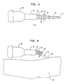
- ridges 33 are formed in flexible section 34. Upon angular movement of end 42 of catheter 32, ridges 33 and the portion of the catheter 35 positioned between ridges 33 expands. Ridges 33 provide support to flexible section 34 without collapsing inner diameter D 2 of flexible section 34, as shown in Fig. 4.
- Catheter 32 can be formed of an elastic or a ductile material.
- An elastic material allows catheter 32 to return to a straightened position after flexing of flexible section 34.
- a ductile material allows catheter 32 to remain in a fixed position after flexing of flexible section 34.
- catheter 32 is a hollow tubular molded polyurethane resin.
- catheter 32 can be formed ofTefion@, which is a registered trademark of Dupont, Dover, Delaware. It will be appreciated to those skilled in the art that other materials could be used for forming catheter 32.
- Fig. 5 illustrates catheter assembly 30 after insertion into patient 36 at insertion site 38.
- Flexible section 34 allows catheter 32 to flex when angular pressure is applied to catheter 32 without constricting inner diameter D 2 of catheter 32.
- Flexible section 34 preferably can flex up to an angle of 180° from the point of insertion of the catheter into the patient at insertion site 38. Flow of fluids through catheter 32 remains constant after flexible section 34 is flexed.
- the present invention has the advantage of increasing performance of an over-the-needle catheter and increasing patient comfort during use of the catheter. If a patient moves resulting in the catheter placement moving, the catheter of the present invention flexes to maintain constant flow of fluids through the catheter. The catheter is more stable after insertion into the patient and does not require extensive taping to prevent movement of the catheter. Accordingly, the catheter reduces the need for reinsertion of the catheter.
Abstract
Description
- This invention relates to a method and apparatus for improving performance of an over-the-needle catheter by using a flexible catheter.
- An over-the-needle catheter is a surgical device for insertion into the tissues of a body cavity. A needle and a concentric outer catheter are inserted into the vein of a patient. After insertion, the needle is withdrawn through the emplaced catheter. Fluids can be introduced or removed through the catheter. The problem of providing constant flow of fluids through a catheter after insertion of the catheter into the body while providing patient comfort during administration of the intended medicament has persisted in the medical community.
- A typical catheter assembly is described in U.S. Patent No. 4,747,831 for enhancing patient comfort during insertion of the catheter. In this assembly, a catheter cannula fits snugly, but removably, onto the forwardly projecting part of a needle. The cannula is made of a biologically inert, but very slippery material for ease of insertion of the cannula into the patient. It is disclosed that Teflon is the material used for forming the cannula.
- One conventional solution for improving flow of fluids through a catheter while reducing patient discomfort during insertion of the catheter is to use an expandable catheter. U.S. Patent No. 5,061,254 describes a catheter formed of hydrophilic thermoplastic elastomeric polyurethane tubing. A small gauge size catheter can be inserted into the patient. When the catheter comes into contact with a body fluid, such as blood, it absorbs water and expands to a larger gauge size. The larger gauge size of the catheter allows for increased flow of fluids through the catheter.
- Prior art catheters have the disadvantage that the catheter can become deformed or kinked if the patient moves after the catheter is inserted in the vein. It is typical to move the patient to change the patient's clothes and linens. Also, with portable intravenous (I.V.) units, the patient may walk around after insertion of the catheter. Patient movement disturbs the site of insertion of the catheter and applies angular pressure to the end of the catheter adjacent to the catheter hub. One conventional solution for preventing movement of the catheter, after insertion of the catheter into the patient, is to elaborately tape the catheter to the arm of the patient. However, even with h taping of the catheter in place, the patient's movements can still deform the catheter.
- If the catheter becomes deformed, fluids can be partially or fully restricted from flowing through the catheter. It is often necessary to re-tape the catheter to try to straighten out a deformed catheter. However, reinsertion of the needle into the catheter can cause severance of the catheter. In the alternative, a needle of a replacement over-the-needle catheter can be reinserted into the patient in order to resume flow of fluids to the patient. Reinsertion of the needle causes additional discomfort to the patient.
- Of possible general relevance to the invention are U.S. Patent Nos.: 4,850,961; 4,964,854; and 5,000,740 which describe assemblies for over-the-needle catheters.
- A practical solution to the problem of maintaining constant flow through a catheter after insertion of the catheter is not found in the prior art.
- Briefly described, the present invention relates to a flexible catheter for improving the performance of an over-the-needle catheter. A flexible section of the catheter is preferably positioned at the end of the catheter adjacent to the catheter hub. Preferably, the flexible section is formed by partial compression of the catheter during molding or extrusion of the catheter, thereby forming ridges in the catheter. Upon angular movement of the catheter, the portion of the catheter between the ridges expands to provide support to the catheter and to maintain a constant inner diameter of the catheter. An elastic material can be used to form the flexible section for allowing the catheter to return to a straightened position after flexing of the flexible section. The flexible catheter can flex up to an angle of 180° from the point of insertion into the patient. The flexible catheter has the advantage of increasing performance of the catheter by maintaining constant flow of fluids through the catheter.
-
- Fig. 1 is a side elevational view of a prior art over-the-needle catheter.
- Fig. 2 is a side elevational view of an over-the-needle catheter assembly of the present invention.
- Fig. 3 is a cross sectional view of the catheter of the present invention shown in Fig. 2.
- Fig. 4 is a side elevational view of flexible portion of the catheter of the present invention.
- Fig. 5 is a side elevational view of the catheter of the present invention after insertion of the catheter into the arm of a patient.
- During the course of this description like numbers will be used to identify like elements according to the different figures which illustrate the invention.
- Fig. 1 is a side elevational view of a prior
art catheter assembly 10.Catheter 10 can be of the type described in U.S. Patent No. 5,000,740.Catheter 10 includes aneedle housing 20 which is semi-tubular in shape. Molded on the sides ofneedle housing 20 arefinger grips 22. At a distal end of catheter housing 20, catheter 14 extends fromcatheter hub 16 and is concentric therewith. Preferably,catheter hub 16 is hollow. A larger diameterproximal portion 18 ofcatheter hub 16 is coupled toneedle housing 20.Needle 12 is concentric with catheter 14 and can be moved between ause position 23 for insertingneedle 12 into the patient and astorage position 21 inhousing 20 afterneedle 12 is inserted into a patient. A point ofneedle 12 extends from catheter 14 during insertion of catheter 14 into the patient. After insertion of the catheter, catheter 14 can be bent or deformed if the patient moves. When catheter 14 is bent or deformed, inner diameter D1 of catheter 14 is reduced. - Fig. 2 illustrates a
catheter assembly 30 in accordance with the principals of the present invention.Catheter 32 includesflexible section 34. Preferably,flexible section 34 is positioned at theend 33 ofcatheter 32 adjacent tocatheter hub 16. The length offlexible section 34 is dependent on the length ofcatheter 32 wherein a longer catheter will have a longer flexible section. The length offlexible section 34 is typically defined as about 0.1 inches to about 5.0 inches and the length ofcatheter 32 is generally about 0.5 inches to about 10 inches. It will be appreciated that the length of the flexible section and the length of the catheter can vary depending on the intended use of the catheter. -
Catheter 32 is preferably attached tocatheter hub 16 by means of ametal eyelet 40 to provide a compression fit betweencatheter 32 andcatheter hub 16, as shown in Fig. 3. In the alternative,catheter 32 can be attached by an adhesive tocatheter hub 16. It will be appreciated that other means of attachment of the catheter to the catheter hub can be used. Alternatively,catheter 32 can be integral withcatheter hub 16. -
Flexible section 34 is preferably formed by partial compression ofcatheter 32 during molding or extrusion of the catheter. In the alternative,flexible section 34 can be formed as a subsequent operation after formingcatheter 38. Heat can be applied tocatheter 32 for aiding compression of the catheter. After compression,ridges 33 are formed inflexible section 34. Upon angular movement ofend 42 ofcatheter 32,ridges 33 and the portion of thecatheter 35 positioned betweenridges 33 expands.Ridges 33 provide support toflexible section 34 without collapsing inner diameter D2 offlexible section 34, as shown in Fig. 4. -
Catheter 32 can be formed of an elastic or a ductile material. An elastic material allowscatheter 32 to return to a straightened position after flexing offlexible section 34. A ductile material allowscatheter 32 to remain in a fixed position after flexing offlexible section 34. Preferably,catheter 32 is a hollow tubular molded polyurethane resin. In the alternative,catheter 32 can be formed ofTefion@, which is a registered trademark of Dupont, Dover, Delaware. It will be appreciated to those skilled in the art that other materials could be used for formingcatheter 32. - Fig. 5 illustrates
catheter assembly 30 after insertion intopatient 36 atinsertion site 38.Flexible section 34 allowscatheter 32 to flex when angular pressure is applied tocatheter 32 without constricting inner diameter D2 ofcatheter 32.Flexible section 34 preferably can flex up to an angle of 180° from the point of insertion of the catheter into the patient atinsertion site 38. Flow of fluids throughcatheter 32 remains constant afterflexible section 34 is flexed. - The present invention has the advantage of increasing performance of an over-the-needle catheter and increasing patient comfort during use of the catheter. If a patient moves resulting in the catheter placement moving, the catheter of the present invention flexes to maintain constant flow of fluids through the catheter. The catheter is more stable after insertion into the patient and does not require extensive taping to prevent movement of the catheter. Accordingly, the catheter reduces the need for reinsertion of the catheter.
- While the invention has been described with reference to the preferred embodiment, this description is not intended to be limiting. It will be appreciated by those of ordinary skill in the art that modifications may be made without departing from the spirit and scope of the invention.
Claims (10)
Applications Claiming Priority (2)
| Application Number | Priority Date | Filing Date | Title |
|---|---|---|---|
| US94145492A | 1992-09-08 | 1992-09-08 | |
| US941454 | 1992-09-08 |
Publications (2)
| Publication Number | Publication Date |
|---|---|
| EP0588546A2 true EP0588546A2 (en) | 1994-03-23 |
| EP0588546A3 EP0588546A3 (en) | 1994-12-14 |
Family
ID=25476490
Family Applications (1)
| Application Number | Title | Priority Date | Filing Date |
|---|---|---|---|
| EP93307042A Ceased EP0588546A3 (en) | 1992-09-08 | 1993-09-07 | Flexible catheter. |
Country Status (5)
| Country | Link |
|---|---|
| EP (1) | EP0588546A3 (en) |
| JP (1) | JPH06210003A (en) |
| AU (1) | AU4499893A (en) |
| CA (1) | CA2105499A1 (en) |
| ZA (1) | ZA936590B (en) |
Cited By (5)
| Publication number | Priority date | Publication date | Assignee | Title |
|---|---|---|---|---|
| WO1995033507A1 (en) * | 1994-06-03 | 1995-12-14 | Rajko Kenda | Catheter and a novel use of a flexible tube |
| EP0771573A1 (en) * | 1995-11-03 | 1997-05-07 | Cordis Corporation | Kink resistant catheter sheath introducer |
| WO2016122304A3 (en) * | 2015-01-30 | 2016-09-22 | Equipos Médicos Vizcarra, S.A. | Central venous catheter with adhesive hub and elastic tubing |
| WO2016204761A1 (en) * | 2015-06-18 | 2016-12-22 | Avent, Inc. | Expandable strain relief sleeve for a catheter assembly |
| WO2018033628A1 (en) * | 2016-08-19 | 2018-02-22 | B. Braun Melsungen Ag | Needle assemblies and related methods |
Families Citing this family (1)
| Publication number | Priority date | Publication date | Assignee | Title |
|---|---|---|---|---|
| US10232140B2 (en) | 2007-12-18 | 2019-03-19 | Becton, Dickinson And Company | Anti-occlusion catheter adapter |
Citations (6)
| Publication number | Priority date | Publication date | Assignee | Title |
|---|---|---|---|---|
| FR2340741A1 (en) * | 1976-02-12 | 1977-09-09 | Intermedicat Gmbh | TIP FOR CATHETER |
| US4160450A (en) * | 1977-07-15 | 1979-07-10 | Doherty George O | Outside-the-needle catheter device with needle housing |
| EP0281421A2 (en) * | 1987-03-05 | 1988-09-07 | Luther Medical Products, Inc. | Assembly of needle and protector |
| EP0448395A1 (en) * | 1990-03-22 | 1991-09-25 | Critikon, Inc. | Stickless catheter with interconnecting nose |
| EP0467703A1 (en) * | 1990-07-20 | 1992-01-22 | Critikon, Inc. | Catheter with needle guard |
| WO1992018193A1 (en) * | 1991-04-22 | 1992-10-29 | Ludger Meyer | Indwelling vein cannula |
-
1993
- 1993-08-30 AU AU44998/93A patent/AU4499893A/en not_active Abandoned
- 1993-09-03 CA CA002105499A patent/CA2105499A1/en not_active Abandoned
- 1993-09-07 EP EP93307042A patent/EP0588546A3/en not_active Ceased
- 1993-09-07 ZA ZA936590A patent/ZA936590B/en unknown
- 1993-09-07 JP JP5246190A patent/JPH06210003A/en active Pending
Patent Citations (6)
| Publication number | Priority date | Publication date | Assignee | Title |
|---|---|---|---|---|
| FR2340741A1 (en) * | 1976-02-12 | 1977-09-09 | Intermedicat Gmbh | TIP FOR CATHETER |
| US4160450A (en) * | 1977-07-15 | 1979-07-10 | Doherty George O | Outside-the-needle catheter device with needle housing |
| EP0281421A2 (en) * | 1987-03-05 | 1988-09-07 | Luther Medical Products, Inc. | Assembly of needle and protector |
| EP0448395A1 (en) * | 1990-03-22 | 1991-09-25 | Critikon, Inc. | Stickless catheter with interconnecting nose |
| EP0467703A1 (en) * | 1990-07-20 | 1992-01-22 | Critikon, Inc. | Catheter with needle guard |
| WO1992018193A1 (en) * | 1991-04-22 | 1992-10-29 | Ludger Meyer | Indwelling vein cannula |
Cited By (12)
| Publication number | Priority date | Publication date | Assignee | Title |
|---|---|---|---|---|
| WO1995033507A1 (en) * | 1994-06-03 | 1995-12-14 | Rajko Kenda | Catheter and a novel use of a flexible tube |
| US5807354A (en) * | 1994-06-03 | 1998-09-15 | Kenda; Rajko | An implantable catheter having intermediate length section of greater flexibility than remaining lengths |
| EP0771573A1 (en) * | 1995-11-03 | 1997-05-07 | Cordis Corporation | Kink resistant catheter sheath introducer |
| WO2016122304A3 (en) * | 2015-01-30 | 2016-09-22 | Equipos Médicos Vizcarra, S.A. | Central venous catheter with adhesive hub and elastic tubing |
| WO2016204761A1 (en) * | 2015-06-18 | 2016-12-22 | Avent, Inc. | Expandable strain relief sleeve for a catheter assembly |
| AU2015399047B2 (en) * | 2015-06-18 | 2020-09-24 | Avent, Inc. | Expandable strain relief sleeve for a catheter assembly |
| US10799670B2 (en) | 2015-06-18 | 2020-10-13 | Avent, Inc. | Expandable sleeve for a catheter assembly |
| WO2018033628A1 (en) * | 2016-08-19 | 2018-02-22 | B. Braun Melsungen Ag | Needle assemblies and related methods |
| CN110022926A (en) * | 2016-08-19 | 2019-07-16 | B.布劳恩梅尔松根股份公司 | Needle assemblies and correlation technique |
| US20210138200A1 (en) * | 2016-08-19 | 2021-05-13 | B. Braun Melsungen Ag | Needle assemblies and related methods |
| AU2017312325B2 (en) * | 2016-08-19 | 2022-11-17 | B. Braun Melsungen Ag | Needle assemblies and related methods |
| CN110022926B (en) * | 2016-08-19 | 2023-06-23 | B.布劳恩梅尔松根股份公司 | Needle assembly and related method |
Also Published As
| Publication number | Publication date |
|---|---|
| AU4499893A (en) | 1994-03-17 |
| JPH06210003A (en) | 1994-08-02 |
| ZA936590B (en) | 1995-03-07 |
| EP0588546A3 (en) | 1994-12-14 |
| CA2105499A1 (en) | 1994-03-09 |
Similar Documents
| Publication | Publication Date | Title |
|---|---|---|
| US7198066B2 (en) | Device for supporting and stabilising a tubing for fluid transport and such a tubing | |
| US5357961A (en) | Catheter guidewire and flushing apparatus and method of insertion | |
| US5176659A (en) | Expandable intravenous catheter and method of using | |
| US5823961A (en) | Catheter guidewire and flushing apparatus and method of insertion | |
| JP2579308B2 (en) | Caterpillar assembly and use thereof | |
| US5607407A (en) | Catheter assembly | |
| EP0125844B1 (en) | Valved two-way catheter | |
| US5690617A (en) | Adjusting catheter holding device | |
| CA1125613A (en) | Winged catheter placement assembly | |
| US6045734A (en) | Process of making a catheter | |
| JP2998956B2 (en) | Arterial catheter and catheter / needle assembly with improved flow characteristics | |
| US5749859A (en) | Catheter or cannula system | |
| US4671796A (en) | Valved two-way catheter | |
| US5318546A (en) | Method of catheter irrigation and aspiration | |
| MXPA97005550A (en) | Arterial catheter and catheter and needle unit with best flow characteristics and method for your | |
| EP1475125A3 (en) | Balloon catheter with floating stiffener, and procedure | |
| WO1987001598A1 (en) | Syringe with pressure sensing means | |
| EP1441793A1 (en) | Intravascular microcatheter having hypotube proximal shaft with transition | |
| JP2015517384A (en) | Crushable inflatable catheter | |
| EP1606003A1 (en) | Valved hub for a catheter | |
| JPH08224312A (en) | Stylet and stylet connector | |
| US20210290926A1 (en) | Spring-based devices, systems, and methods to faciliate vascular access | |
| JPH10113395A (en) | Position blowoff blood gasket for safety catheter and manufacture therefor | |
| EP0588546A2 (en) | Flexible catheter | |
| JPS61122873A (en) | Operable catheter and its use |
Legal Events
| Date | Code | Title | Description |
|---|---|---|---|
| PUAI | Public reference made under article 153(3) epc to a published international application that has entered the european phase |
Free format text: ORIGINAL CODE: 0009012 |
|
| AK | Designated contracting states |
Kind code of ref document: A2 Designated state(s): CH DE ES FR GB IT LI |
|
| PUAL | Search report despatched |
Free format text: ORIGINAL CODE: 0009013 |
|
| AK | Designated contracting states |
Kind code of ref document: A3 Designated state(s): CH DE ES FR GB IT LI |
|
| 17P | Request for examination filed |
Effective date: 19950517 |
|
| 17Q | First examination report despatched |
Effective date: 19970117 |
|
| GRAG | Despatch of communication of intention to grant |
Free format text: ORIGINAL CODE: EPIDOS AGRA |
|
| STAA | Information on the status of an ep patent application or granted ep patent |
Free format text: STATUS: THE APPLICATION HAS BEEN REFUSED |
|
| 18R | Application refused |
Effective date: 19980919 |