EP0590145B1 - Fiber optic sensor and methods for detecting an organic analyte in a fluid or vapor sample - Google Patents
Fiber optic sensor and methods for detecting an organic analyte in a fluid or vapor sample Download PDFInfo
- Publication number
- EP0590145B1 EP0590145B1 EP93912211A EP93912211A EP0590145B1 EP 0590145 B1 EP0590145 B1 EP 0590145B1 EP 93912211 A EP93912211 A EP 93912211A EP 93912211 A EP93912211 A EP 93912211A EP 0590145 B1 EP0590145 B1 EP 0590145B1
- Authority
- EP
- European Patent Office
- Prior art keywords
- polarity
- light energy
- sensitive dye
- immobilized
- optical fiber
- Prior art date
- Legal status (The legal status is an assumption and is not a legal conclusion. Google has not performed a legal analysis and makes no representation as to the accuracy of the status listed.)
- Expired - Lifetime
Links
Images


Classifications
-
- G—PHYSICS
- G01—MEASURING; TESTING
- G01N—INVESTIGATING OR ANALYSING MATERIALS BY DETERMINING THEIR CHEMICAL OR PHYSICAL PROPERTIES
- G01N21/00—Investigating or analysing materials by the use of optical means, i.e. using sub-millimetre waves, infrared, visible or ultraviolet light
- G01N21/75—Systems in which material is subjected to a chemical reaction, the progress or the result of the reaction being investigated
- G01N21/77—Systems in which material is subjected to a chemical reaction, the progress or the result of the reaction being investigated by observing the effect on a chemical indicator
- G01N21/7703—Systems in which material is subjected to a chemical reaction, the progress or the result of the reaction being investigated by observing the effect on a chemical indicator using reagent-clad optical fibres or optical waveguides
-
- G—PHYSICS
- G01—MEASURING; TESTING
- G01N—INVESTIGATING OR ANALYSING MATERIALS BY DETERMINING THEIR CHEMICAL OR PHYSICAL PROPERTIES
- G01N21/00—Investigating or analysing materials by the use of optical means, i.e. using sub-millimetre waves, infrared, visible or ultraviolet light
- G01N21/62—Systems in which the material investigated is excited whereby it emits light or causes a change in wavelength of the incident light
- G01N21/63—Systems in which the material investigated is excited whereby it emits light or causes a change in wavelength of the incident light optically excited
- G01N21/64—Fluorescence; Phosphorescence
- G01N21/6428—Measuring fluorescence of fluorescent products of reactions or of fluorochrome labelled reactive substances, e.g. measuring quenching effects, using measuring "optrodes"
- G01N2021/6434—Optrodes
-
- G—PHYSICS
- G01—MEASURING; TESTING
- G01N—INVESTIGATING OR ANALYSING MATERIALS BY DETERMINING THEIR CHEMICAL OR PHYSICAL PROPERTIES
- G01N21/00—Investigating or analysing materials by the use of optical means, i.e. using sub-millimetre waves, infrared, visible or ultraviolet light
- G01N21/75—Systems in which material is subjected to a chemical reaction, the progress or the result of the reaction being investigated
- G01N21/77—Systems in which material is subjected to a chemical reaction, the progress or the result of the reaction being investigated by observing the effect on a chemical indicator
- G01N21/7703—Systems in which material is subjected to a chemical reaction, the progress or the result of the reaction being investigated by observing the effect on a chemical indicator using reagent-clad optical fibres or optical waveguides
- G01N2021/7706—Reagent provision
- G01N2021/773—Porous polymer jacket; Polymer matrix with indicator
-
- G—PHYSICS
- G01—MEASURING; TESTING
- G01N—INVESTIGATING OR ANALYSING MATERIALS BY DETERMINING THEIR CHEMICAL OR PHYSICAL PROPERTIES
- G01N21/00—Investigating or analysing materials by the use of optical means, i.e. using sub-millimetre waves, infrared, visible or ultraviolet light
- G01N21/75—Systems in which material is subjected to a chemical reaction, the progress or the result of the reaction being investigated
- G01N21/77—Systems in which material is subjected to a chemical reaction, the progress or the result of the reaction being investigated by observing the effect on a chemical indicator
- G01N2021/7793—Sensor comprising plural indicators
Definitions
- the research for the present invention was supported by a grant from the Northeast Hazardous Substances Research Center, an Environmental Protection Agency Research Center for Federal Regions 1 and 2, through the Tufts Center for Environmental Management.
- the present invention is concerned with optical sensors and optical sensing apparatus utilizing colorimetric or fluorometric techniques as qualitative and quantitative detection systems; and is particularly directed to fiber optic sensors utilizing polarity sensitive solvachromic dyes and polymeric materials capable of absorbing and partitioning organic analytes for optical determinations.
- spectroscopy has been divided into individual and distinctly different methods and instrumentation systems for: ultraviolet and visible spectrophotometry; fluorescence and phosphorescence spectrophotometry; flame emission and atomic absorption spectrometry; atomic emission spectroscopy; infrared spectrophotometry; raman spectroscopy; nuclear magnetic resonance spectroscopy; electron spin resonance spectroscopy; refractometry and interferometry; and various others.
- the optical sensors and optical sensing detection systems utilizing the ultraviolet and visible absorption methods and the fluorescence and phosphorescence excitation and emission systems are perhaps the best known and commonly utilized.
- optical fibers and optical fiber strands in combination with light energy absorbing dyes for medical, environmental, and chemical analytical determinations has undergone rapid development especially within the last decade.
- the use of optical fibers for such purposes and techniques generally is described by the following publications: Milanovich et al . "Novel Optical Fiber Techniques for Medical Application.” Proceedings of the SPIE 28th Annual International Technical Symposium on Optics and Electro-Optics, Volume 294, 1980; Seitz, W.R., "Chemical Sensors Based on Immobilized Indicators and Fiber Optics," in C.R.C. Critical Reviews in Analytical Chemistry , Vol.
- the optical fiber strands employed for analytical determinations typically are glass or plastic extended rods having a small cross-sectional diameter.
- proximal end When light energy is projected into one end of the fiber strand (conventionally termed the “proximal end"), the angles at which the various light energy rays strike the surface are greater than the critical angle; and such rays are "piped” through the strand's length by successive internal reflections and eventually exit from the opposite end of the strand (conventionally termed the "distal end”).
- bundles of these strands are used collectively as optical fibers in a variety of different applications.
- light energy is photoenergy and is defined as electromagnetic radiation of any wavelength. Accordingly, the terms "light energy” and “photoenergy” include infrared, visible, and ultraviolet wavelengths conventionally employed in most optical instruments and apparatus; the term also includes the other spectral regions of x-ray and microwave wavelengths (although these are generally not used in conjunction with optical fibers).
- light from an appropriate energy source is used to illuminate what is chosen to be the proximal end of an optical fiber or a fiber bundle.
- the light propagates along the length of the optical fiber; and a portion of this propagated light energy exits the distal end of the optical fiber and is absorbed by one or more light energy absorbing dyes.
- the light energy absorbing dye may or may not be immobilized; may or may not be directly attached to the optical fiber itself; may or may not be suspended in a fluid sample containing one or more analytes of interest to be detected; and may or may not be retainable for subsequent use in a second optical determination.
- optical fibers Of the many different classes of light absorbing dyes which may be employed with single optical fiber strands and with bundles of optical fibers for different analytical purposes are those compositions which emit light energy after first absorbing energy and are termed “fluorophores”; and those compositions which absorb light energy and internally convert the absorbed light energy into heat or kinetic energy rather than emit it as light and are termed “chromophores” or “absorbers”. Fluorophores and fluorescent detection methods employing optical fibers are recognized as being markedly different and distinguishable from light energy absorbance and absorption spectroscopy.
- Fluorescence is a physical phenomenon based upon the ability of some molecules to absorb light energy (photons) at specified wavelengths and then emit light energy of a longer wavelength and at a lower energy. Such emissions are called fluorescence if the emission is relatively long-lived, typically 10 -11 to 10 -7 seconds. Substances able to fluoresce share and display a number of common characteristics: they absorb light energy at one wavelength or frequency; reach an excited energy state; and subsequently emit light at another light frequency and energy level. The absorption and fluorescence emission spectra are thus individual for each fluorophore; and are often graphically represented as two separate curves which are slightly overlapping.
- fluorophores demonstrate the Stokes' shift - that is, the emitted light is always at a longer wavelength (and at a lower energy level) relative to the wavelength (and energy level) of the exciting light absorbed by the substance. Moreover, the same fluorescence emission spectrum is generally observed irrespective of the wavelength of the exciting light and, accordingly, the wavelength and energy of the exciting light may be varied within limits; but the light emitted by the fluorophore will always provide the same emission spectrum as emerging light. Finally, fluorescence may be measured as the quantum yield of light emitted. The fluorescence quantum yield is the ratio of the number of photons emitted in comparison to the number of photons initially absorbed by the fluorophore.
- Dyes which absorb light energy as chromophores do so at individual wavelengths of energy and are characterized by a distinctive molar absorption coefficient for light energy at that wavelength.
- Chemical analyses employing fiber optic strands and absorption spectroscopy using visible and ultraviolet light wavelengths in combination with the absorption coefficient allow for the determination of concentration for specific analytes of interest by spectral measurement.
- absorbance measurement via optical fibers The most common use of absorbance measurement via optical fibers is to determine concentration which is calculated in accordance with Beers' law; accordingly, at a single absorbance wavelength; the greater the quantity of the composition which absorbs light energy at a given photo wavelength, the greater the optical density for the sample. In this way, the total quantity of light absorbed directly correlates with the quantity of the composition in the sample.
- optical fiber sensors in both qualitative and quantitative analytical determinations concern the desirability of depositing and/or immobilizing various light absorbing dyes at the distal end of the optical fiber using a given technique or apparatus.
- a variety of different optical fiber chemical sensors and methods have been reported for specific analytical determinations and applications such as pH measurement. oxygen detection, and carbon dioxide analyses.
- a fiber-optic potassium ion sensor using dodecyl acridine orange in a plasticized poly (vinyl chloride) membrane is disclosed in Anal. Chem. 62 :1528 (1990). This requires use of a neutral ionophore (valinomycin).
- the present invention provides optical fiber articles, apparatus, and methods able to be employed in the field for low cost and reliable systems for monitoring the environment in a timely and continuous manner.
- One aspect of the present invention thus provides a fiber optic sensor for detecting an organic analyte of interest in a fluid sample, said fiber optic sensor comprising:
- a second aspect of the present invention provides a method for detecting an organic analyte of interest in a fluid sample, said method comprising the steps of:
- Yet a third aspect of the present invention provides a method for making a fiber optical sensor able to detect an organic analyte of interest in a fluid sample, said method comprising the steps of:
- the present invention is a marked improvement in fiber optic sensors, apparatus, and methods for performing qualitative and quantitative optical measurements and determinations of organic analytes.
- the physical construction of this singular and unique fiber optic sensor and the manner of its manufacture are the most critical and demanding aspects of the subject matter as a whole which is the present invention.
- the apparatus, the methods for making optical determinations, and the systems of qualitative and quantitative detection subsequently described are based and rely upon the existence and use of the properly constructed fiber optic sensors as the essential article.
- the present invention is definable alternatively in multiple formats as a fiber optic sensor, an apparatus, a method for detection, and a method of manufacture; and may be employed in a variety of divergent purposes and applications to detect a large and diverse range of organic analytes of interest, the subject matter as a whole which is the present invention will be presently described in multiple textual sections individually and collectively in order that the prospective user may more quickly recognize and appreciate their major differences and distinctions in comparison to the fiber optic sensors, apparatus, and systems conventionally known today.
- the singular fiber optic sensor is comprised of three essential components: an optical fiber strand; at least one polarity-sensitive or solvachromic dye immobilized at the distal end of the optical fiber strand; and at least one polymeric material immobilized at the distal end of the optical fiber strand such that the immobilized polarity-sensitive solvachromic dye is contained within (i.e., dispersed in and enclosed by) the polymeric material.
- an optical fiber strand at least one polarity-sensitive or solvachromic dye immobilized at the distal end of the optical fiber strand
- at least one polymeric material immobilized at the distal end of the optical fiber strand such that the immobilized polarity-sensitive solvachromic dye is contained within (i.e., dispersed in and enclosed by) the polymeric material.
- a preferred optical fiber strand is illustrated by Figs. 1 and 2A and 2B.
- an individual optical fiber strand 10 is comprised of a single optical fiber 12 having a cylindrical shaft 14 and two fiber ends 16,18, each of which provides a substantially planar end surface.
- the intended distal surface 20 at the fiber end 16 is illustrated by Fig. 2A while the intended proximal surface 22 at the fiber end 18 is illustrated within Fig. 2B.
- the optical fiber 12 is composed typically of glass or plastic and is a flexible entity able to convey light energy introduced at either of its ends 16,18.
- Such optical fibers 12 are conventionally known and commercially available.
- the user may himself prepare optical fibers in accordance with the conventional practices and techniques reported by the scientific and industrial literature. For these reasons, the optical fiber 12 is deemed to be conventionally known and available as such.
- Figs. 1-2 are illustrations in which the features have been purposely magnified and exaggerated beyond their normal scale in order to provide both clarity and visualization of extreme detail.
- the conventional optical fiber strand has a cross-section diameter of 10-1,000 micrometers and is routinely employed in lengths ranging between centimeters (in the laboratory) to kilometers (in field telecommunications).
- the optical fiber is illustrated via Figs. 1-2 an extended cylinder having substantially circular proximal and distal end surfaces, there is no requirement or demand that this specific configuration be maintained.
- the optical fiber may be polygonal or asymmetrically shaped along its length; provide special patterns and shapes at the proximal and/or distal faces; and need not present an end surface which is substantially planar. Nevertheless, for best results, it is presently believed that the substantially cylindrical rod-like optical fiber strand having planar end surfaces is most desirable.
- Each optical fiber strand 12 is desirably, but not necessarily, individually clad by cladding 26 axially along its length.
- This cladding 26 is composed of any material which has a lower refractive index and prevents the transmission of light energy photons from the optical fiber 12 to the external environment.
- the cladding material 26 may thus be composed of a variety of radically different chemical formulations including various glasses, silicones, plastics, cloths, platings, and shielding matter of diverse chemical composition and formulation.
- the manner in which the optical fiber 12 is clad is consequential and of no importance to the present invention. Those methods of deposition, extrusion, painting, and covering are scientifically and industrially available; and any of these known processes may be chosen to meet the requirements and convenience of the user.
- the quantity of cladding employed need be only that minimal amount which effectively prevents light energy conveyed by the optical fiber 12 from escaping into the general surroundings. It will be recognized and appreciated therefore that the depth of cladding 26 as appears within Figs. 1 and 2 respectively is greatly exaggerated and purposely thickened in order to show the general relationship; and is without scale or precise ratio between the cladding 26 and the optical fiber 12.
- Figs. 1 and 2 the configuration of the cladding 26 as appears within Figs. 1 and 2 has been shaped as a round coating as a preferred embodiment only. Alternatively, it is often desirable that the cladding take shape in specific multi-sided and regular geometric forms such as a round, oval, circular, or even irregular shape.
- the illustrated configuration is merely one embodiment of the cladding 26 as it extends co-axially along the length of the optical fiber strand 10.
- Fig. 1 reveals the individually clad, optical fiber strand 12 in partial cross-section views to demonstrate the relationship between the optical fiber 12 and the cladding 26 which is coextensive along its length.
- the distal end 16 of the optical fiber strand 10 is substantially cylindrical in shape and desirably presents a surface 20 which is substantially planar and smooth.
- the surface 32 includes a depression or well 34 which extends into the substance of the optical fiber 12 at a depth typically of several micrometers.
- the well 34 appears substantially circular within Fig. 3B, oval or irregularly configured depressions may also be employed as fits the needs or convenience of the user.
- the void volume of the well 34 from its greatest depth to the surface 32 may also be considerably varied.
- Fig. 3B will increase the quantity of dye materials deposited and also permit a greater surface area of dye for reactive contact on the surface for specific uses and assay applications.
- the greatest possible surface area configurations of the distal end surface may be highly desirable; nevertheless, for most general assay purposes, both quantitative and qualitative, the intended distal surface illustrated within Fig. 3A as a substantially planar and smooth surface is deemed to be suitable and desirable.
- the second critical requirement and feature of the present fiber optic sensor is the presence of at least one polarity-sensitive or solvachromic dye immobilized at the intended distal end of the optical fiber strand.
- Solvachromic dyes regardless of specific composition and formulation, are identified and defined in operational terms as a light energy absorbing substance whose absorption and/or emission spectra are sensitive to and altered by the polarity of their surrounding environment - including gaseous, liquid, and/or solid molecules and ions which are temporarily or permanently present in the immediately adjacent spatial volume.
- solvachromic is derived from the recognized and long established characteristics of many fluorophores whose fluorescence emission spectra are sensitive to the polarity of the solvents in which they are employed or found.
- solvachromic dyes While the best known examples of solvachromic dyes are fluorophores, the membership of this class as a whole includes both absorbers or chromophores as well as fluorescent molecules.
- the essential property common to each and every member of this class of dyes is that the chosen dye substance change its spectral properties when exposed to different solvents of varying polarity.
- this spectral change can include either an emission intensity change or a change in the wavelength of the emitted fluorescent light.
- the intensity of color may change or the absorption spectrum of the dye may shift either toward the red or the blue end of the spectrum.
- the test is solely an empirical one.
- the dye When the dye is exposed to different organic solvents of varying polarity, the dye changes its color which is empirically observed as a spectral change.
- an absorber dye demonstrates a spectral change through its color, either by altering the intensity of the color or by the observation of an actual color change.
- a fluorescent dye demonstrates its sensitivity to different solvents of varying polarity through changes in either its absorbing exciting light; or by a change in wavelength of the emitted light; or by a change in the intensity of the emitted light.
- solvachromic and polarity-sensitive are directly related and often interchangeable. The meaning of each of these terms, however, is not exactly alike.
- polarity-sensitive dye defines and identifies a dye formulation which is not only sensitive to different solvents of varying polarity, but also to any other organic entity, molecule, or substance which has a discernable - that is, a demonstrable or determinable - polarity.
- organic compositions, compounds, and formulations of varying polarity which are not solvents as such are clearly encompassed and included by this term in addition to those compositions which are classically defined as "organic solvents.”
- organic solvents constitute merely one group or family within the membership as a whole for the class of organic analytes having a discernable polarity.
- any other kind or type of organic molecule may also be employed to demonstrate the spectral sensitivity of the chosen dye - albeit under less convenient and/or more rigorous test conditions.
- Table 1 provides a representative list of polarity-sensitive fluorophores.
- Table 2 provides a range of illustrative examples which are polarity-sensitive absorber or chromophoric dyes.
- the third and final required component comprising the fiber optic sensor is the existence of at least one polymeric material immobilized at the distal end of the optical fiber strand such that the immobilized polarity-sensitive dye is contained within, that is dispersed, enclosed, and/or encompassed by - this polymeric material.
- the first characteristic and function is the primary role of the polymeric material - capturing the organic analyte of interest to be detected. This capture function and capability is performed by absorbing and partitioning the organic analyte of interest within the substance and thickness of the polymeric material itself as it lies immobilized at the distal end of the optical fiber strand.
- the absorption and partition occurs between the vapor or liquid phase of the fluid sample and the polymeric material forming one component of the sensor construction.
- the partitioning of the organic analyte of interest may be similar within the fluid sample and in the polymeric material, that is the concentration of vapor in each of these two phases may be the same: or more likely, one of the two will be enriched in concentration of the organic analyte relative to the other.
- the polymeric material layer will serve to concentrate the organic analyte of interest via its superior solubility characteristics relative to the vapor or liquid phase.
- the polymeric material will concentrate the organic analyte, which in turn, increases the sensitivity and detection limit of the sensor as a unit.
- the second function and characteristic of the polymeric material which will not be present to a similar degree in all embodiments of the fiber optic sensor, is the spectral influence exerted by the polymeric material and its ability to alter or modify the spectral characteristics of the dye - independent and separate from the spectral influences and consequences caused by the organic analyte of interest.
- This second property and characteristic will often vary with the degree of polarity or the non-polarity of the polymer material as individually chosen for use in constructing the specific embodiment. Polarity as such, however, is not the sole property or mechanism by which the dye's spectral properties are mediated or affected.
- the properties of the polymeric material containing the immobilized polarity-sensitive dye at the distal end of the optical fiber strand may or may not itself alone influence and alter the spectral characteristics of the immobilized solvachromic dye apart from and prior to introduction of an organic analyte in a fluid sample.
- the essential value and circumstance lies in the polymeric material interacting with the immobilized polarity-sensitive dye and thus providing a background or baseline of dye interaction and of dye spectral properties against which all other or subsequent optical determinations and measurements are made and compared.
- a background or baseline set of spectral properties for the immobilized and contained dye is produced which are the result and consequence of only the interaction between the polymeric material and the polarity-sensitive dye. It is this baseline or background set of spectral characteristics against which all optical determinations and changes in spectral properties are subsequently made and measured for the detection of an organic analyte of interest.
- the organic analytes become captured, absorbed, and partitioned by the polymeric material and generate marked changes in the spectral properties of the immobilized polarity-sensitive dye in the sensor.
- the spectral light absorbing and light emitting characteristics of the immobilized dye become changed from its background or baseline standard provided by the effect of the polymeric material alone.
- the sensors described herein are not controlled in operation or function by any particular mechanism of action.
- the spectral changes exhibited by the sensors which may be operative, will include: (1) polarity changes in the polymeric material generated by the organic analyte of interest which consequently can impart changes in the spectral properties of the dyes, as these dyes are sensitive to polarity; (2) concentration quenching wherein dyes can associate with one another and through this association diminish their light intensity, the degree of association being influenced by the presence or absence of the organic analyte; (3) changes orientational in nature, in which the polymer, in the presence of the organic analyte, orients the dye in a particular way which creates an environment for changes in spectral properties; and (4) swelling in which the distance between dye molecules changes as a function of the volume change in the polymeric material caused by the introduction of the organic analyte.
- the analytes which may be optically detected and measured using the present invention individually and collectively share several characteristics and properties.
- the first and foremost property is that the organic analyte have a discernible polarity.
- the polarity includes polarity of bonds caused by two atoms joined by a covalent bond which share electrons unequally; and the polarity of molecules which occurs if the center of negative charge does not coincide with the center of positive charge within the molecular structure and thus constitutes a dipole.
- the second commonly shared characteristic of the organic analytes having a discernible polarity is that they may in fact be in any physical state - that is in a gaseous, liquid, or even in a fluid-solid state. It is required that the organic analyte be able to migrate within or be carried by a fluid sample; to be absorbed and at least partially partitioned by the polymeric material immobilized at the tip of the sensor; and that the absorbed and partitioned analyte of interest present in the polymeric material layer meaningfully alter or modify the baseline set of spectral properties generated by the interaction of the immobilized solvachromic dye with the polymeric material which exists prior to introduction of the analyte of interest.
- the organic analyte of interest may be detected, identified, and determined optically by the present invention.
- analytes suitable for detection by the present invention are expected primarily to be in the vapor or liquid physical states; and, moreover, that these be recognized conventionally as organic solvents which are well known and employed in research and industry. Nevertheless. such organic substances which appear as fluid solids in the field or in-situ are also suitable for detection and measurement using the present invention.
- hydrocarbons are composed primarily of carbon and hydrogen atoms; but may also contain one or more heteroatoms selected from the group consisting of nitrogen, oxygen, sulfur, and halogen atoms.
- These hydrocarbons, with or without one or more heteroatoms, may be saturated or unsaturated; may take shape as linear, branched, ring, or polycyclic structures; and present format which include aliphatic and aryl hydrocarbon structures or combinations of these.
- hydrocarbon molecule as a whole, exclusive of any heteroatoms which may optionally be present, will comprise from 1 to about 25 carbon atoms in total; and that within this range of carbon atoms, one or more degrees of saturation; linear, branched, and ring entities; and multiple structural format will be present.
- the fiber optic sensor and method of detection are particularly valuable for the detection of hydrocarbons principally present in petroleum products. These include petroleum aromatics, naphthalenes, paraffins, and olefins which are present within crude oil or derived as petroleum products.
- the fiber optic sensor is particularly sensitive to and exceptionally able to detect lower molecular weight liquid hydrocarbons because such molecules have high solubility in and high diffusivities within the chosen polymeric material - thus permitting rapid absorption and partition by the polymeric material and a measurable change in the spectral properties of the immobilized polarity-sensitive dye within a reasonably fast response time, in comparison, for organic analytes which are normally gaseous (such as methane, ethane, and ethylene) the sensor is expected to have lower sensitivity in response because of the lower solubility of these analytes within the polymeric materials generally expected to be employed within the fully constructed sensor.
- High molecular weight liquid hydrocarbons would also be expected to take a somewhat longer time to be detected in comparison to low molecular weight hydrocarbons because of lower diffusivities in the polymeric material.
- any organic analyte which can penetrate and be captured by the polymeric material of the sensor (and thus be absorbed and partitioned during its migration) is suitable for detection using the present invention.
- the differences among the various hydrocarbons and other organic compounds would be only in the magnitude of their individual effects upon the polarity-sensitive dye; and the time required for the sensor to respond spectrally to the presence of the organic analytes within the fluid sample.
- Aromatics such as benzene, toluene, the xylenes, ethyl benzene, naphthalene, anthracene, phenanthrene, plus their hydrocarbon derivatives; Naphthenes (saturated cyclics) such as cyclohexane, tetralin, and their hydrocarbon derivatives; Paraffins (branched and straight chain) such as propane; normal and isobutane; all paraffinic isomers of C5, C6, C7, C8, C9, and C10; Olefins such as propylene; the butylenes; all olefinic isomers of C5, C6, C7, C8, C9, and C10; Halogenated hydrocarbons comprising chlorine, bromine, fluorine, or
- the manufacture of the fiber optic sensor as described herein requires that the polarity-sensitive dye and the polymeric material each be deposited and immobilized at the intended distal end of at least one optical fiber strand. Not only must each of these components be immobilized at the tip of the optical fiber strand; but also it is required that the immobilized polymeric material enclose and encompass the entirety of the polarity-sensitive dye to achieve the intended construction organization.
- a highly desirable approach and method for manufacture purposefully combines the polarity-sensitive dye with monomers, or copolymers, or prepolymers to form the polymer; and then polymerizes or cross-links the mixture in-situ directly at the intended distal end of the optical fiber strand.
- the polarity-sensitive dye is intimately intermixed and dispersed within the substance and thickness of the polymeric material and does not present any discrete format or layer as such.
- the preferred method of deposition and immobilization is via a coating polymerization and employs an admixture of monomers and/or prepolymers with one or more pre-chosen polarity-sensitive dye as a formulation.
- Such admixture preparations typically comprise solutions of several monomers and/or prepolymers in admixture and a concentration of at least one polarity-sensitive dye.
- a representative listing of different monomer and prepolymer compositions suitable for preparing an admixture are given by Table 5.
- Such admixtures subsequently can be polymerized or solidified by solvent evaporation to form the desired polymer matrix.
- An illustrative listing of polarity-sensitive dyes ready for admixture and polymerization is given previously by Table 1 and 2 above.
- the optical fiber strand used to construct the sensor was 600 ⁇ m in diameter, 5 m in length, having a numerical aperture of 0.37 and coated with a protective plastic jacket (Ensign-Bickford Optics Co., Avon, CT).
- the proximal end was coupled to a fluorometer by an Optimate Connector (AMP Inc., Harrisburg, PA).
- AMP Inc. Harrisburg, PA
- the distal end was stripped, cleaved, polished, and then cleaned with concentrated sulfuric acid.
- the sensor configuration and materials are shown in Fig. 4.
- the sensing layer was applied by solvent evaporation.
- the distal tip was dipped into a solution containing 0.314 mM Nile Red (Molecular Probes, Eugene, OR) and 10% (v/v) Dow Corning (Lansing, MI) dispersion coating compound in toluene and allowed to dry.
- the Dow compound is a dimethylsilicone polymer that has an infinite molecular weight when cross-linked. This procedure was repeated until the fiber's distal face was coated with a light-pink layer, approximately 10-50 ⁇ m thick as observed with a microscope.
- the delicate distal end of the fiber was fitted with a light impermeable, porous, stainless steel sheath to protect the sensing layer.
- FIG. 5 A block diagram of an apparatus constituting the portable hydrocarbon fluorometer is shown in Fig. 5.
- the illuminating light from a quartz halogen lamp was focused into a 600 ⁇ m diameter fiber and conducted to an optical coupler, where the appropriate excitation wavelength was selected by a 540 nm bandpass filter.
- a beam splitter was used to discriminate and direct returning fluorescence light through a 600 nm longpass filter before it impinged on a photodiode.
- the signal was conditioned electronically and output to a hard-copy port.
- the instrument was packaged into an aluminum case, having the dimensions 46 cm long x 36 cm wide x 18 cm high. weighing 13 kg, requiring 100 V, 60 Hz power for operation.
- Nile Red The optical properties of Nile Red allow it to be used readily in the detection of organic compounds. It has been used commonly as a lipophilic dye in staining cells and membranes and as a solvent polarity indicator. Although its solvachromic behavior has been described, it has not been investigated extensively. Its fluorescence excitation and emission maxima vary with the hydrophobicity of its microenvironment. For example, the emission maxima of Nile Red in heptane and acetone are 525 and 605 nm, respectively. These optical properties may be exploited by creating a microenvironment that is sensitive and susceptible to changes in hydrophobicity.
- an organic-vapor sensing layer can be constructed by incorporating Nile Red into a thin siloxane polymer layer on the distal face of an optical fiber. As the polymer layer is exposed to organic vapors, absorption causes the microenvironment of Nile Red to become more nonpolar, resulting in fluorescence enhancement of the fluorophore.
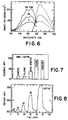
- Fig. 6 displays the increase in intensities of both the excitation and emission spectra of a sensor placed in the headspace above three different concentrations of benzene acquired with the research instrument; and show the excitation and emission spectra of a sensor exposed to 0.100, and 200 ppm benzene.
- the excitation spectra were collected by scanning the excitation monochromator from 400 to 550 nm and monitoring the emission at 580 nm.
- the emission spectra were collected by measuring the emission from 530 to 650 nm, using an excitation wavelength of 500 nm. These spectra were taken by the method of sampling described under Measurements.
- the emission signal increases from 238.000 cps in 0 ppm benzene to 625,000 cps in 200 ppm benzene. This dramatic increase in intensity is caused by absorption of benzene into the polymer microenvironment of Nile Red, resulting in enhanced fluorescence.
- the fluorescence emission maximum shifts from approximately 560 to 570 nm, corresponding to the solvachromic sensitivity of Nile Red. This shift could be attributed to the benzene-absorbed polymer microenvironment stabilizing the excited state of the fluorophore, shifting the wavelength maximum to lower energy and, therefore, longer wavelengths. This effect is consistent with stabilization of the excited state in n- ⁇ * or ⁇ - ⁇ * electronic transitions.
- Fig. 7 shows the responses of a sensor to the individual components of the conventional BTEX series (benzene, toluene, ethylbenzene, xylene) and unleaded gasoline at 100 ppm with the field portable instrument.
- concentration of gasoline being a multicomponent species, is defined as the number of microliters of gasoline per liter of water. No attempt was made to calculate the vapor-phase concentration.
- the sensor is most sensitive to xylene in the BTEX series, it responds equally well to gasoline, indicating that the sensor responds generally to a wide variety of volatile organic vapors.
- FIG. 8 A typical sensor response to increasing concentrations of p-xylene as a function of time can be seen in Fig. 8.
- the baseline response was measured in the headspace of a flask containing only distilled water.
- a sharp rise in voltage occurs, followed by a slower leveling off as equilibrium is established between the headspace and sensing-layer vapor concentrations.
- Fig. 8 indicates that the sensor response time is established in less than 2.5 minutes as defined by the signal reaching 90% of its final value.
- the recovery times defined by the signal decreasing to within 10% of the starting baseline values, are longer; for example, for 10 and 160 ppm the recovery times are 2.5 and 10 minutes, respectively.
- the desorption process is retarded probably by nonspecific hydrophobic interactions between the absorbed organic vapor and the hydrophobic polymer/dye layer.
- the rate-determining process is the diffusion of the vapor into and out of the polymer layer, restricting the sensor's response and dictating the frequency of sampling.
- Fig. 9 shows calibration curves for xylene and gasoline, indicating very good linearity in the concentration range of 10-160 ppm.
- the variation in slopes is due to sensitivity differences of the sensor to xylene and gasoline. Below 10 ppm, vapor detection is possible, but nonlinear behavior is observed.
- the sensor can detect 1 ppm gasoline but cannot be used to make quantitative measurements due to the nonlinearity of the calibration curve in this region. However, it is still very useful in situations that require information as to the presence or absence of a contaminant, such as in leak detection from underground storage tanks.
- the sensor response is related directly to the vapor pressure of the organic component. During data collection on the samples investigated above, a constant temperature was maintained throughout the measurement process.
- a sensor was placed in a sampling vial containing only distilled water and was submerged into a temperature-controlled water bath.
- the fluorescence signal decreased due to acceleration of the thermal relaxation processes as the temperature was raised from 4 to 30°C as shown in Fig. 10.
- the sensor shows an increase in response as temperature increases. This is illustrated by Fig. 11.
- This result can be explained by four effects influencing sensor response simultaneously.
- the vapor pressure of the organic component increases with temperature, providing a greater headspace concentration.
- the polymer layer structure may become more amorphous, causing a decrease in porosity and a greater exclusion of water vapor. Water vapor could act as an interference by increasing the polarity of the membrane.
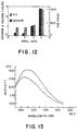
- Initial Field Data The purpose of the initial field work was to show that the sensor responds qualitatively to in-situ field concentrations and that the system was field-hardened. No attempt was made to critically evaluate the sensor's performance with that of established field methods (i.e.. gas chromatography or photoionization probe (PID)).
- the field studies were performed in cooperation with Morlock Environmental and were conducted at Pease Air Force Base, NH, at a site contaminated with JP4 jet fuel. Four individual wells were measured in-situ with the fiber-optic sensor and its supporting instrumentation and these measurements were compared to simultaneous readings from a portable Photovac TIP PID, with a 10.2-eV lamp.
- the PID measurements were used as a relative indicator of contamination between sites, allowing us to test the response of the sensor to in-situ samples of different concentrations.
- the sensor was calibrated with benzene by the method described under Measurements and the PID was spanned between air and 100 ppm (aqueous solution) benzene standard.
- the reported values in Fig. 12 for the PID are "benzene equivalents," which should approximate the extent of contamination in each well.
- Fig. 12 shows the response of a sensor in each well at a depth of 3.5 m below ground level, compared to concentrations measured concurrently with the PID.
- the PID measurements indicate that the four drill sites have varying degrees of contamination.
- the fiber-optic sensor responded comparably to in-situ concentrations of JP4 in each monitoring well. Moreover, the sensor responded semiquantitatively to the different degrees of contamination as defined by the PID.
- the approach of using a microenvironmentally sensitive fluorophore and organic vapor permeable polymer as a sensing mechanism has proven successful in the laboratory and from initial field studies.
- the sensor responds to environmentally significant levels of light mononuclear aromatics (BTEX series) and gasoline in the laboratory and responds to in-situ samples of VOCs. From the wide range of compounds studied, the sensor should generally respond to virtually any organic volatile compound.
- BTEX series light mononuclear aromatics
- the approach described has several advantages: the sensors are inexpensive to construct and provide true real-time, in-situ measurements; sensors respond almost instantaneously to the presence of VOCs, enabling a large number of samples to be measured; their small size allows smaller diameter sampling wells to be drilled; and sensors can be used in situations where electrical devices pose risks.
- Pair Polarity-Sensitive Dye Polymeric Material 1 Fluorescein dissolved parafilm 2 Acrylodan dissolved parafilm 3 Dansyl lysine dissolved parafilm 4 Anthracene-9-carbox- dimethyl methylvinyl aldehyde carbohydrazone siloxance 5 Octadecyl rhodamine dimethyl methylvinyl silicone 6 Nile Red dimethyl silicone
- a bare optical fiber was dip-coated to produce a thin layer of acrylodan/parafilm.
- Acrylodan was selected because it is environmentally sensitive and has been used to test ligand binding.
- Parafilm was used because it is a wax-like substance and allows the absorption of hydrocarbons. Furthermore, it was readily available.
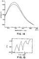
- Fig. 13 shows the response of the fully constructed acrylodan/parafilm sensor to gasoline exposure. The emission spectrum decreases in intensity on exposure to toluene. This sensor was tested on a xenon arc lamp research grade fiber optic fluorometer.
- Fig. 14 empirically shows that the fluorescence of the solvachromic dye decreases on exposure to pure toluene. This combination suffered from the same troubles as the previous acrylodan/parafilm signal sensor - such as poor solubility in the polvmer: weak fluorescence; and a decreased signal on exposure to organic vapor.
- the data of Fig. 14 shows the emission spectrum of a dansyl lysine/parafilm sensor exposed to toluene.
- Fig. 15 shows the response of a sensor made out of the copolymer when exposed to 333 ⁇ l of toluene in 1.0 liter of air. It was evident that the large increase in signal, averaging 14%, was a vast improvement that could be attributed to the change in polymer.
- a lipophilic dye would be a better choice of solvachromic fluorophore due to its improved solubility in organic solvents and desirable solvachromic behavior.
- the first lipophilic dye evaluated was octadecyl rhodamine B chloride salt or "ODR". This lipophilic dye has several advantages over dyes tested previously: it has a greater solubility in organic solvents; it does not partition out of the polymer due to its long octadecyl tail; it has excitation and emission peaks at longer wavelengths (ex 540, em 580); and it has good photostability.
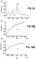
- Fig. 16 shows the excitation spectrum of octadecylrhodamine in the copolymer dimethyl and methyl vinyl siloxane on exposure to gasoline (100 ul of gasoline in 1 liter of air) taken at different time intervals: (1) after 1 minute; (2) after 2 minutes: and (3) after 3 minutes.
- gasoline 100 ul of gasoline in 1 liter of air
- 17 shows the emission spectrum of octadecylrhodamine in the copolymer dimethyl and methylvinyl siloxane on exposure to gasoline taken as different time intervals (100 ⁇ l of gasoline in 1 liter of air): (1) after 1 minute; (2) after 2 minutes; (3) after 5 minutes: and (4) after 7 minutes.
- Figs. 19A-19C show the response of this sensor to three different concentrations of gasoline.
- Fig. 19A shows exposure to 1 ⁇ l gasoline in 6 liters of air;
- Fig. 19B shows exposure to 10 ⁇ l gasoline in 6 liters of air;
- Fig. 19C shows exposure to 20 ⁇ l gasoline in 6 liters of air.
- the equilibrium intensity values can be used to generate a calibration plot as shown by Fig. 20.
- the data are the mean standard deviation of three measurements.
- Fig. 21 illustrates slope calibration measured after 90 minutes of four different ODR/DM MV siloxane sensors.
- the data are the mean standard deviation of three measurements.
- Fig. 21 shows the changes in slope that occur over the first 60 minutes of exposure are responsive to the different concentration of gasoline used.
- Fig. 22 shows dye concentration as a function of fluorescence signal and demonstrates a maximum intensity at a dilution corresponding to 1.15 x 10 -3 M/L.
- the dye concentration that produces the largest signal change with the smallest change in exposure corresponds to the concentration in Fig. 22 at the left edge of the peak: 1.7 x 10 -3 M/L.
- Table 8 shows the average ratio change on exposure to acetone of five different groups of sensors made with an increasing concentration of dye.
Abstract
Description
| POLARITY-SENSITIVE FLUOROPHORES |
| Phospholipid Fluorophores |
| N-(7-nitrobenz-2-oxa-1,3-diazol-4-yl) dipalmitoyl-L-a-phosphatidylethanolamine (NBD-PE) |
| N-(5-fluoresceinthiocarbamoyl) dipalmitoyl-L-a-phosphatidylethanolamine triethylammonium salt (fluorescein-PE) |
| N-(6-tetramethylrhodaminethiocarbamoyl) dipalmitoyl-L-a-phosphatidylethanolamine triethylammonium salt (TRITC DPPE) |
| N-(Lissamine rhodamine B sulfonyl) dipalmitoyl-L-a-phosphatidylethanolamine triethylammonium slat (rhodamine DPPE) |
| N-(Texas Red sulfonyl) dioleoyl-L-a-phosphatidylethanolamine triethylammonium salt |
| N-(Texas Red sulfonyl) dipalmitoyl-L-a-phosphatidylethanolamine triethylammonium salt (Texas Red DPPE) |
| 3-palmitoyl-s-(1-pyrenedecanoyl)-L-a-phosphatidylcholine (10-py-PC) |
| N-(5-dimethylaminonaphthalene-1-sulfonyl) dipalmitoyl-L-a-phosphatidylethanolamine triethylammonium salt |
| N-(1-pyrenesulfonyl) dipalmitoyl-L-a-phosphatidylethanolamine triethylammonium salt |
| N-(6-(5-dimethylaminonaphthalene-1-sulfonyl) amino) hexanoyldipalmitoyl-L-a-phosphatidylethanolamine triethylammonium salt |
| N-(biotinoyl) dipalmitoyl-L-a-phosphatidylethanolamine triethylammonium salt |
| Anionic Fluorophores |
| cis-parinaric acid |
| trans-parinaric acid |
| p-((6-phenyl)-1,3,5-hexatrienyl) benzoic acid (DPH carboxylic acid) |
| 3-(p-(6-phenyl)-1,3,5-hexatrienyl) phenylpropionic acid (DPH propionic acid) |
| 1-pyrenecarboxylic acid |
| 1-pyrenebutanoic acid (pyrenebutyric acid) |
| 1-pyrenenonanoic acid |
| 1-pyrenedecanoic acid |
| 1-pyrenedodecanoic acid |
| 1-pyrenehexadecanoic acid |
| 11-(1-pyrenesulfonyl) amino) undecanoic acid |
| 2-(9-anthroyloxy) palmitic acid (2-AP) |
| 2-(9-anthroyloxy) stearic acid (2-AS) |
| 3-(9-anthroyloxy) stearic acid (3-AS) |
| 6-(9-anthroyloxy) stearic acid (6-AS) |
| 7-(9-anthroyloxy) stearic acid (7-AS) |
| 9-(9-anthroyloxy) stearic acid (9-AS) |
| 10-(9-anthroyloxy) stearic acid (10-AS) |
| 11-(9-anthroyloxy) undecanoic acid (11-AU) |
| 12-(9-anthroyloxy) stearic acid (12-AS) |
| 12-(9-anthroyloxy) oleic acid (12-AO) |
| 16-(9-anthroyloxy) palmitic acid (16-AP) |
| 9-anthracenepropionic acid |
| 9-anthracenedodecanoic acid |
| 1-perylenedodecanoic acid |
| 6-(N-(7-nitrobenz-2-oxa-1,3-diazol-4-yl) amino) hexanoic acid (NBD hexanoic acid) |
| 12-(N-methyl-N-((7-nitrobenz-2-oxa-1,3-diazol-4-yl) amino) dodecanoic acid |
| 12-(N-methyl-N-((7-nitrobenz-2-oxa-1,3-diazol-4-yl) amino) octadecanoic acid |
| 12-(N-(7-nitrobenz-2-oxa-1,3-diazol-4-yl) amino) dodecanoic acid |
| 11-(9-carbazole) undecanoic acid (11-CU) |
| 11-((5-dimethylaminonaphthalene-1-sulfonyl) amino) undecanoic acid |
| 5-(N-dodecanoyl) aminofluorescein |
| 5-(N-hexadecanoyl) aminofluorescein |
| 5-(N-octadecanoyl) aminofluorescein |
| 5-(N-hexadecanoyl) aminoeosin |
| 1-anilinonaphthalene-8-sulfonic acid (1,8-ANS) |
| 2-anilinonaphthalene-6-sulfonic acid (2,6-ANS) |
| 2-(p-toluidinyl) naphthalene-6-sulfonic acid sodium salt (2,6-TNS) |
| 2-(N-methylanilino) naphthalene-6-sulfonic acid sodium salt (2,6-MANS) |
| bis-ans (1,1'-bis(4-anilino) naphthalene-5,5'-disulfonic acid, dipotassium salt) |
| 1-pyrenesulfonic acid, sodium salt |
| 2-(N-octadecyl) aminonaphthalene-6-sulfonic acid, sodium salt |
| Cationic Fluorophores |
| 1,1'-dihexadecyloxacarbocyanine, perchlorate (DiOC16(3)) |
| 3,3'-dioctadecyloxacarbocyanine perchlorate ("DiO", DiOC18(3)) |
| 1,1'-didodecyl-3,3,3',3'-tetramethylindocarbocyanine, perchlorate (DilC12(3)) |
| 1,1'-dihexadecyl-3,3,3',3'-tetramethylindocarbocyanine perchlorate (DilC16(3)) |
| 1,1'-dioctadecyl-3,3,3',3'-tetramethylindocarbocyanine perchlorate (":Dil", DilC18(3)) |
| 1,1'-didocosanyl-3,3,3',3'-tetramethylindocarbocyanine perchlorate (DilC22(3)) |
| 1,1'-dioctadecyl-3,3',3'-tetramethylindocarbocyanine perchlorate (DilC18(5)) |
| 3,3'-dioctadecylthiacarbocyanine perchlorate (DiSC18(3)) |
| octadecyl rhodamine B, chloride salt (R 18) |
| rhodamine 6G, octadecyl ester, chloride |
| rhodamine 101, octadecyl ester, chloride |
| N-4- (4-didecylaminostyryl)-N-methylpyridinium iodide (4-di-10-ASP) |
| 1-(4-trimethylammoniumphenyl)-6-phenyl-1,3,5-hexatriene, p-toluenesulfonate (TMA-DPH) |
| 6-palmitoyl-2-(((2-(trimethyl) ammonium) ethyl) methyl) amino) naphthalene, chloride (PATMAN) |
| 1-pyrenemethyltrimethylammonium iodide |
| 1-pyrenebutyltrimethylammonium bromide |
| 3-(-anthracene) propyl trimethylammonium bromide |
| acridine orange-10-dodecyl bromide (dodecyl acridine orange) |
| acridine orange-10-nonyl bromide (nonyl acridine orange |
| Neutral Fluorophores |
| 1,6-diphenyl-1,3,5-hexatriene (DPH) |
| 1-phenyl-6-((4-trifluoromethyl) phenyl)-1,3,5-hexatriene (CF3- DPH) |
| palladium disodium alizarinmonosulfonate (Pd(QS)2) |
| Nile Red or 9-diethylamino-5H-benzo[a] phenoxazine-5-one |
| 6-propionyl-2-dimethylaminonaphthalene (prodan) |
| 6-dodecanoyl-2-dimethylaminonaphthalene (laurodan) |
| N-phenyl-1-naphthylamine |
| 1,10-bis-(1-pyrene) decane |
| 1,3-bis-(1-pyrene) propane |
| p-dimethylaminobenzylidenemalononitrile |
| N-(5-dimethylaminonaphthalene-1-sulfonyl) hexadecylamine |
| N-(5-dimethylaminonaphthalene- 1-sulfonyl) dihexadecylamine |
| 4-(N,N-dihexadecyl) amino-7-nitrobenz-2-oxa-1,3-diazole (NBD dihexadecylamine) |
| 4-(N,N-dioctyl) amino-7-nitrobenz-2-oxa-1,3-diazole (NBD-dioctylamine) |
| 4-(hexadecylamino)-7-nitrobenz-2-oxa-1,3-diaxole (NBD hexadecylamine) |
| 1-pyrenecarboxaldehyde |
| 1-pyrenenonanol |
| 7-dimethylamino-4-pentadecylcoumarin |
| cholesteryl anthracene-9-carboxylate |
| 1-pyrenemethyl 36-hydroxyl-22,23-bisnor-5-cholenate (PMC) |
| 1-pyrenemethyl 38-(cis-9-octadecenoyloxy)-22,23-bisnor-5-cholenate (PMC oleate) |
| 25-(NBD-methylamino)-27-norcholesterol (NBD-MANC) |
| 25-(NBD-methylamino)-27-norcholesteryl oleate (NBD-MANC oleate) |
| 22-(N-(7-nitrobenz-2-oxa-1,3-diazol-4-yl) amino)-23,24-bisnor-5-cholen-38-ol |
| 22-(N-(7-nitrobenz-2-oxa-1,3-diazol-4-yl) amino)-23-24-bisnor-5-cholen-38-yl linoleate |
| N-(3-sulfopropyl)-4-(p-didecylaminostyryl) pyridinium, inner salt (Di10ASP-PS) |
| 3-(N,N-dimethyl-N-(-pyrenemethyl) ammonium) propanesulfonate, inner salt |
| 4-(N,N-dimethyl-N-(1-pyrenemethyl) ammonium) butanesulfonate, inner salt |
| N-ε-(5-dimethylaminonaphthalene-1-sulfonyl)-L-lysine (dansyl lysine) |
| POLARITY-SENSITIVE CHROMOPHORES |
| Phospholipid Chromophores |
| 2(3-diphenylhexatrienyl) propanoyl-3-palmitoyl-L-a-phosphatidyl choline (DPH-PC) |
| N-(6-(biotinoyl) amino hexanoyl) dipalmitoyl-L-a-phosphatidylethanolamine triethyl ammonium salt (biotin-X-DPPE) |
| N-((4-maleimidylmethyl) cyclohexane-1-carbonyl) dipalmitoyl-L-a-phosphatidyl-ethanolamine triethylammonium salt (MMCC-DPPE) |
| N-((2-pyridyldithio) propionyl) dipalmitoyl-L-a-phosphatidyl-ethanolamine triethylammonium salt |
| Anionic Chromophores |
| 15-phenylpentadecanoic acid |
| 5-(N-hexadecanoyl) amino fluorescein diacetate |
| POLYMERIC MATERIALS |
| Silicones and Silicon-Containing Polymers |
| Monomeric and oligomeric fluids (including silahydrocarbons) |
| Polydimethylsiloxanes - conventional fluids |
| Polydimethylsiloxanes, silanol and moisture cure prepolymers |
| Polydimethylsiloxanes, vinyl termination |
| Polydimethylsiloxanes, functional termination |
| Polydimethylsiloxanes, vinyl functional copolymers |
| Polydimethylsiloxanes, copolymers with functional groups |
| T-structure polymers with functionality |
| Organohydrosiloxane polymers and copolymers |
| Polymethylalkylsiloxanes |
| Fluoroalkylsiloxanes |
| Aromatic (phenyl containing) siloxanes |
| Aromatic polymers with functional groups |
| Aromatic substituted alkyl polysiloxanes |
| Silicone gums |
| Non-siloxane-siloxane copolymers |
| Polysilanes |
| Polysilazanes |
| Polyalkoxysiloxanes-Polysilicates (including sol-gel intermediates) |
| T-resins and ladder polymers |
| Silane-modified polymers (including polymeric coupling agents) |
| Other Polymers |
| polyethylene |
| polypropylene |
| polymethylmethacrylate |
| polystyrene |
| polyhydroxyethylmethacrylate |
| polyurethanes |
| polyvinylchloride |
| polyvinylidene chloride |
| fluorinated polyolefins |
| chlorofluoropolyolefins |
| polysubstituted siloxanes |
| Parafilm |
| HYDROCARBONS FROM PETROLEUM SOURCES SUITABLE FOR DETECTION |
| Aromatics such as benzene, toluene, the xylenes, ethyl benzene, naphthalene, anthracene, phenanthrene, plus their hydrocarbon derivatives; |
| Naphthenes (saturated cyclics) such as cyclohexane, tetralin, and their hydrocarbon derivatives; |
| Paraffins (branched and straight chain) such as propane; normal and isobutane; all paraffinic isomers of C5, C6, C7, C8, C9, and C10; |
| Olefins such as propylene; the butylenes; all olefinic isomers of C5, C6, C7, C8, C9, and C10; |
| Halogenated hydrocarbons comprising chlorine, bromine, fluorine, or iodine; and |
| Hydrocarbons of up to 25 carbon atoms containing one or more carbonyl groups (-CO) forming aldehydes and ketones. |
| A. | Monomers |
| acrylamide | |
| N,N-methylene bis(acrylamide) | |
| hydroxyethylmethacrylate | |
| styrene | |
| vinyl acetate | |
| N-(3-aminopropyl) meth-acrylamide hydrochloride [Kodak. Inc.] | |
| B. | Comonomer With Dimethylsiloxane |
| (acryloxypropyl) methyl (15-20%) | |
| (aminopropyl) methyl (3-5%) | |
| (methacryloxypropyl) methyl (2-3%) | |
| C. | T-Structure Polydimethylsiloxanes |
| methacryloxypropyl (25-50% | |
| Vinyl (50-75%) | |
| D. | Waxes/Preformed Polymers |
| paraffin | |
| polyvinyl alcohol |
| Pair | Polarity-Sensitive | Polymeric Material | |
| 1 | Fluorescein | dissolved | |
| 2 | Acrylodan | dissolved | |
| 3 | Dansyl lysine | dissolved | |
| 4 | Anthracene-9-carbox- | dimethyl methylvinyl | |
| aldehyde carbohydrazone | siloxance | ||
| 5 | Octadecyl rhodamine | dimethyl methylvinyl | |
| silicone | |||
| 6 | Nile Red | dimethyl silicone |
| VALUES OF THE ACRYLODAN/PARAFILM SENSORS EXPOSED TO TOLUENE | ||||||
| Concentration | Time | Kcps | | Time | Kcps | |
| 0 | 1 | 208 | 200 | 13 | 168 | |
| 2 | 204 | 14 | 189 | |||
| 3 | 207 | 15 | 186 | |||
| 4 | 204 | 16 | 180 | |||
| 200 | 5 | 167 | 0 | 17 | 228 | |
| 6 | 173 | 18 | 229 | |||
| 7 | 170 | 19 | 232 | |||
| 8 | 169 | 20 | 238 | |||
| 0 | 9 | 182 | 200 | 21 | 215 | |
| 10 | 197 | 22 | 215 | |||
| 11 | 195 | 23 | 216 | |||
| 12 | 195 | 24 | 216 |
| SENSOR RATIO DATA OF OPTIMUM DYE CONCENTRATION | ||
| Group | Dye Concentration Molar (10-3) | Average Ratio Ix/Io |
| A | 0.5 | 1.26 |
| B | 1.0 | 1.17 |
| C | 1.7 | 1.34 |
| D | 2.5 | 1.2 |
| E | 4.0 | 1.1 |
| Sensors were exposed to pure acetone. The ratio is Ix/Io (Ix is the intensity on exposure to acetone and Io is the intensity before exposure. |
Claims (10)
- A fiber optic sensor for detecting an organic analyte of interest in a fluid sample, said fiber optic sensor comprising:an optical fiber strand (10) able to convey light energy of a predetermined wavelength, said optical fiber strand (10) having a proximal end (16), a distal end (18; 30), and a strand length;at least one polarity-sensitive dye immobilized at the distal end (18; 30) of said optical fiber strand (10), said polarity-sensitive dye being able to absorb light energy of a predetermined wavelength; andat least one polymeric material immobilized at the distal (18; 30) end of said optical fiber strand (10) such that said immobilized polarity-sensitive dye is contained within said polymeric material, through which at least a portion of such organic analyte as is presented by the fluid sample becomes absorbed by said immobilized polymeric material and a measurable change in the spectral properties of contained polarity-sensitive dye is produced by direct interaction between said immobilized polarity-sensitive dye and said organic analyte;means for introducing light energy of a predetermined wavelength to the proximal end (16) of said fiber optical sensor; andmeans for detecting light energy emitted by said contained polarity-sensitive dye.
- A fiber optic sensor according to claim 1, wherein said optical fiber strand (10) conveys exciting light energy of a first wavelength and emitted light energy of a second wavelength.
- A fiber optic sensor according to claim 1 or claim 2, wherein said polarity-sensitive dye is a chromophore.
- A fiber optic sensor according to claim 1, or claim 2, wherein said polarity-sensitive dye is a fluorophore.
- A fiber optic sensor according to any one of claims 1 to 4, wherein said polymeric material is a silicone based polymer.
- A fiber optic sensor according to any one of claims 1 to 5, wherein said contained polarity-sensitive dye is Nile Red.
- A fiber optic sensor according to any one of claims 1 to 6, wherein said polymeric material is selected from the group consisting of polyethylene, polypropylene, polymethylmethacrylate, polystyrene, polyhydroxyethylmethacrylate, polyurethanes, polyvinyl chlorides, polyvinylidene chloride, fluorinated polyolefins, parafilm, and chlorofluoro polyolefins.
- A fiber optic sensor according to any one of claims 1 to 7, wherein said means for detecting light energy is by detection of emitted light energy of another wavelength.
- A method for detecting an organic analyte of interest in a fluid sample, said method comprising the steps of:contacting the fluid sample comprising the organic analyte of interest with a fiber optical sensor comprised ofan optical fiber strand (10) able to convey light energy of a predetermined wavelength, said optical fiber strand having a proximal end (16), a distal end (18; 30), and a strand length,at least one polarity-sensitive dye, immobilized at the distal end (18; 30) of said optical fiber strand (10), said polarity-sensitive dye being able to absorb light energy of a predetermined wavelength, andat least one polymeric material immobilized at the distal end (18; 30) of said optical fiber strand (10) such that said immobilized polarity-sensitive dye is contained within said polymeric material, through which at least a portion of such organic analyte as is presented by the fluid sample becomes absorbed by said immobilized polymeric material and a measurable change in the spectral properties of said contained polarity-sensitive dye is produced by direct interaction between said immobilized polarity-sensitive dye and said organic analyte;introducing light energy of a predetermined wavelength to the proximal end of said fiber optic strand (10) whereby said light energy is conveyed to said distal end (18; 30) of said strand (10) and said contained polarity-sensitive dye absorbs at least a portion of said light energy; anddetecting light energy emitted by said contained polarity-sensitive dye at said distal end (18; 30) of said fiber optical sensor, said detected light energy being a measure of the organic analyte in the fluid sample.
- A method for making a fiber optical sensor able to detect an organic analyte of interest in a fluid sample, said method comprising the steps of:providing an optical fiber strand (10) able to convey light energy of a predetermined wavelength, said optical fiber strand having a proximal end (16), a distal end (18; 30), and a strand length;admixing at least one polarity-sensitive dye able to absorb exciting light energy of a predetermined wavelength with at least one polymerizable material to form a reaction mixture; andpolymerizing said reaction mixture at the distal end (18; 30) of said optical fiber strand such that said polarity-sensitive dye is contained within an immobilized polymeric material, through which at least a portion of such organic analyte as is presented by the fluid sample becomes absorbed by said immobilized polymeric material and a measurable change in the spectral properties of said contained polarity-sensitive dye is produced by direct interaction between said immobilized polarity-sensitive dye and said organic analyte.
Applications Claiming Priority (3)
| Application Number | Priority Date | Filing Date | Title |
|---|---|---|---|
| US870949 | 1992-04-20 | ||
| US07/870,949 US5244813A (en) | 1991-01-25 | 1992-04-20 | Fiber optic sensor, apparatus, and methods for detecting an organic analyte in a fluid or vapor sample |
| PCT/US1993/003448 WO1993021513A1 (en) | 1992-04-20 | 1993-04-12 | Fiber optic sensor, apparatus, and methods for detecting an organic analyte in a fluid or vapor sample |
Publications (3)
| Publication Number | Publication Date |
|---|---|
| EP0590145A1 EP0590145A1 (en) | 1994-04-06 |
| EP0590145A4 EP0590145A4 (en) | 1994-08-24 |
| EP0590145B1 true EP0590145B1 (en) | 1998-09-02 |
Family
ID=25356393
Family Applications (1)
| Application Number | Title | Priority Date | Filing Date |
|---|---|---|---|
| EP93912211A Expired - Lifetime EP0590145B1 (en) | 1992-04-20 | 1993-04-12 | Fiber optic sensor and methods for detecting an organic analyte in a fluid or vapor sample |
Country Status (6)
| Country | Link |
|---|---|
| US (1) | US5244813A (en) |
| EP (1) | EP0590145B1 (en) |
| JP (1) | JPH06508694A (en) |
| CA (1) | CA2111838A1 (en) |
| DE (1) | DE69320742T2 (en) |
| WO (1) | WO1993021513A1 (en) |
Cited By (1)
| Publication number | Priority date | Publication date | Assignee | Title |
|---|---|---|---|---|
| US7002671B2 (en) | 1998-07-17 | 2006-02-21 | Aurora Discovery, Inc. | Detector and screening device for ion channels |
Families Citing this family (177)
| Publication number | Priority date | Publication date | Assignee | Title |
|---|---|---|---|---|
| US5320814A (en) * | 1991-01-25 | 1994-06-14 | Trustees Of Tufts College | Fiber optic array sensors, apparatus, and methods for concurrently visualizing and chemically detecting multiple analytes of interest in a fluid sample |
| US5525520A (en) * | 1992-09-01 | 1996-06-11 | Martin Marietta Energy Systems, Inc. | Photo-activated luminescence sensor and method of detecting trichloroethylene and related volatile organochloride compounds |
| US5416879A (en) * | 1993-03-29 | 1995-05-16 | World Precision Instruments, Inc. | Apparatus and method for measuring light absorption in small aqueous fluid samples |
| IT1265878B1 (en) * | 1993-07-06 | 1996-12-12 | Consiglio Nazionale Ricerche | METHOD FOR THE IMMOBILIZATION OF GLASS SUPPORTS AT THE END OF PLASTIC OR GLASS FIBER OPTICS FOR THE REALIZATION OF SENSORS |
| US5445795A (en) * | 1993-11-17 | 1995-08-29 | The United States Of America As Represented By The United States Department Of Energy | Volatile organic compound sensing devices |
| US5512490A (en) * | 1994-08-11 | 1996-04-30 | Trustees Of Tufts College | Optical sensor, optical sensing apparatus, and methods for detecting an analyte of interest using spectral recognition patterns |
| US5661035A (en) * | 1995-06-07 | 1997-08-26 | The Regents Of The University Of California | Voltage sensing by fluorescence resonance energy transfer |
| US6596522B2 (en) | 1997-05-08 | 2003-07-22 | The Regents Of The University Of California | Detection of transmembrane potentials by optical methods |
| US6342379B1 (en) * | 1995-06-07 | 2002-01-29 | The Regents Of The University Of California | Detection of transmembrane potentials by optical methods |
| US5567622A (en) * | 1995-07-05 | 1996-10-22 | The Aerospace Corporation | Sensor for detection of nitrogen dioxide and nitrogen tetroxide |
| US5814524A (en) * | 1995-12-14 | 1998-09-29 | Trustees Of Tufts College | Optical sensor apparatus for far-field viewing and making optical analytical measurements at remote locations |
| US7041510B2 (en) | 1996-04-25 | 2006-05-09 | Bioarray Solutions Ltd. | System and method for programmable illumination pattern generation |
| US6387707B1 (en) * | 1996-04-25 | 2002-05-14 | Bioarray Solutions | Array Cytometry |
| US6958245B2 (en) | 1996-04-25 | 2005-10-25 | Bioarray Solutions Ltd. | Array cytometry |
| US6251691B1 (en) * | 1996-04-25 | 2001-06-26 | Bioarray Solutions, Llc | Light-controlled electrokinetic assembly of particles near surfaces |
| US7144119B2 (en) * | 1996-04-25 | 2006-12-05 | Bioarray Solutions Ltd. | System and method for programmable illumination pattern generation |
| GB9700745D0 (en) | 1997-01-15 | 1997-03-05 | Univ Strathclyde | Furfuraldehyde detector |
| US7622294B2 (en) * | 1997-03-14 | 2009-11-24 | Trustees Of Tufts College | Methods for detecting target analytes and enzymatic reactions |
| US6023540A (en) * | 1997-03-14 | 2000-02-08 | Trustees Of Tufts College | Fiber optic sensor with encoded microspheres |
| US6327410B1 (en) | 1997-03-14 | 2001-12-04 | The Trustees Of Tufts College | Target analyte sensors utilizing Microspheres |
| US20030027126A1 (en) | 1997-03-14 | 2003-02-06 | Walt David R. | Methods for detecting target analytes and enzymatic reactions |
| US6406845B1 (en) | 1997-05-05 | 2002-06-18 | Trustees Of Tuft College | Fiber optic biosensor for selectively detecting oligonucleotide species in a mixed fluid sample |
| AU756945B2 (en) | 1997-05-23 | 2003-01-30 | Bioarray Solutions Ltd | Color-encoding and in-situ interrogation of matrix-coupled chemical compounds |
| DE19734618A1 (en) * | 1997-08-09 | 1999-02-11 | Boehringer Mannheim Gmbh | Analyser for in-vivo determination of analytes in body of patient |
| DE69802954D1 (en) * | 1997-10-02 | 2002-01-24 | Siemens Canada Ltd | METHOD FOR TEMPERATURE CORRECTION AND SUBSYSTEM FOR AN ARRANGEMENT FOR EVAPORATION LEAK DETECTION OF VEHICLES |
| US7348181B2 (en) | 1997-10-06 | 2008-03-25 | Trustees Of Tufts College | Self-encoding sensor with microspheres |
| US7115884B1 (en) | 1997-10-06 | 2006-10-03 | Trustees Of Tufts College | Self-encoding fiber optic sensor |
| US6098454A (en) * | 1998-02-06 | 2000-08-08 | Zellweger Uster, Inc. | Subsampling fiber testing system |
| US6210910B1 (en) | 1998-03-02 | 2001-04-03 | Trustees Of Tufts College | Optical fiber biosensor array comprising cell populations confined to microcavities |
| US20050147534A1 (en) * | 1998-05-05 | 2005-07-07 | Massachusetts Institute Of Technology | Emissive sensors and devices incorporating these sensors |
| US8198096B2 (en) * | 1998-05-05 | 2012-06-12 | Massachusetts Institute Of Technology | Emissive polymers and devices incorporating these polymers |
| ATE261483T1 (en) * | 1998-05-05 | 2004-03-15 | Massachusetts Inst Technology | LIGHT EMITTING POLYMERS AND DEVICES CONTAINING SAME |
| US6780617B2 (en) | 2000-12-29 | 2004-08-24 | Chen & Chen, Llc | Sample processing device and method |
| US7799521B2 (en) * | 1998-06-24 | 2010-09-21 | Chen & Chen, Llc | Thermal cycling |
| EP2045334A1 (en) | 1998-06-24 | 2009-04-08 | Illumina, Inc. | Decoding of array sensors with microspheres |
| CA2632856C (en) * | 1998-06-24 | 2010-10-12 | Chen & Chen, Llc | Fluid sample testing system |
| US6908770B1 (en) | 1998-07-16 | 2005-06-21 | Board Of Regents, The University Of Texas System | Fluid based analysis of multiple analytes by a sensor array |
| US6349160B2 (en) | 1998-07-24 | 2002-02-19 | Aurora Biosciences Corporation | Detector and screening device for ion channels |
| US6406668B1 (en) | 1998-08-03 | 2002-06-18 | University Of Iowa Research Foundation | Sensing array and sensor structure |
| GB9818766D0 (en) * | 1998-08-28 | 1998-10-21 | Johnson Matthey Plc | Improvements in sensors |
| US6035705A (en) * | 1998-09-01 | 2000-03-14 | Marathon Ashland Petroleum Llc | Method for characterization of fuels |
| US6285807B1 (en) * | 1998-11-16 | 2001-09-04 | Trustees Of Tufts College | Fiber optic sensor for long-term analyte measurements in fluids |
| US6429027B1 (en) | 1998-12-28 | 2002-08-06 | Illumina, Inc. | Composite arrays utilizing microspheres |
| US7510841B2 (en) | 1998-12-28 | 2009-03-31 | Illumina, Inc. | Methods of making and using composite arrays for the detection of a plurality of target analytes |
| US20050026209A1 (en) * | 1999-01-08 | 2005-02-03 | Vann Charles S. | Optical fiber bundle for detecting binding of chemical species |
| ATE343425T1 (en) | 1999-01-08 | 2006-11-15 | Applera Corp | FIBER MATRIX FOR BRINGING CHEMICAL SUBSTANCES TOGETHER, AND METHOD FOR THE PRODUCTION AND USE THEREOF |
| US7595189B2 (en) * | 1999-01-08 | 2009-09-29 | Applied Biosystems, Llc | Integrated optics fiber array |
| US6490030B1 (en) | 1999-01-18 | 2002-12-03 | Verification Technologies, Inc. | Portable product authentication device |
| US6846460B1 (en) | 1999-01-29 | 2005-01-25 | Illumina, Inc. | Apparatus and method for separation of liquid phases of different density and for fluorous phase organic syntheses |
| US6355431B1 (en) | 1999-04-20 | 2002-03-12 | Illumina, Inc. | Detection of nucleic acid amplification reactions using bead arrays |
| US20030207295A1 (en) * | 1999-04-20 | 2003-11-06 | Kevin Gunderson | Detection of nucleic acid reactions on bead arrays |
| US20060275782A1 (en) | 1999-04-20 | 2006-12-07 | Illumina, Inc. | Detection of nucleic acid reactions on bead arrays |
| EP2360270B1 (en) | 1999-05-20 | 2016-11-09 | Illumina, Inc. | Combinatorial decoding of random nucleic acid arrays |
| US6544732B1 (en) | 1999-05-20 | 2003-04-08 | Illumina, Inc. | Encoding and decoding of array sensors utilizing nanocrystals |
| US8481268B2 (en) | 1999-05-21 | 2013-07-09 | Illumina, Inc. | Use of microfluidic systems in the detection of target analytes using microsphere arrays |
| US8080380B2 (en) | 1999-05-21 | 2011-12-20 | Illumina, Inc. | Use of microfluidic systems in the detection of target analytes using microsphere arrays |
| US6132958A (en) * | 1999-05-27 | 2000-10-17 | The Rockefeller University | Fluorescent bead for determining the temperature of a cell and methods of use thereof |
| US6589779B1 (en) | 1999-07-16 | 2003-07-08 | Board Of Regents, The University Of Texas System | General signaling protocol for chemical receptors in immobilized matrices |
| US7022517B1 (en) | 1999-07-16 | 2006-04-04 | Board Of Regents, The University Of Texas System | Method and apparatus for the delivery of samples to a chemical sensor array |
| EP1218545B1 (en) | 1999-08-18 | 2012-01-25 | Illumina, Inc. | Methods for preparing oligonucleotide solutions |
| WO2001018524A2 (en) | 1999-08-30 | 2001-03-15 | Illumina, Inc. | Methods for improving signal detection from an array |
| US7211390B2 (en) | 1999-09-16 | 2007-05-01 | 454 Life Sciences Corporation | Method of sequencing a nucleic acid |
| US7244559B2 (en) | 1999-09-16 | 2007-07-17 | 454 Life Sciences Corporation | Method of sequencing a nucleic acid |
| US6975944B1 (en) * | 1999-09-28 | 2005-12-13 | Alpha Mos | Method and apparatus for monitoring materials used in electronics |
| US7167615B1 (en) | 1999-11-05 | 2007-01-23 | Board Of Regents, The University Of Texas System | Resonant waveguide-grating filters and sensors and methods for making and using same |
| DE60135092D1 (en) | 2000-01-31 | 2008-09-11 | Univ Texas | PORTABLE DEVICE WITH A SENSOR ARRAY ARRANGEMENT |
| US7955794B2 (en) * | 2000-09-21 | 2011-06-07 | Illumina, Inc. | Multiplex nucleic acid reactions |
| US8076063B2 (en) | 2000-02-07 | 2011-12-13 | Illumina, Inc. | Multiplexed methylation detection methods |
| AU2001238067B2 (en) | 2000-02-07 | 2007-01-25 | Illumina, Inc. | Nucleic acid detection methods using universal priming |
| US7611869B2 (en) | 2000-02-07 | 2009-11-03 | Illumina, Inc. | Multiplexed methylation detection methods |
| US6913884B2 (en) * | 2001-08-16 | 2005-07-05 | Illumina, Inc. | Compositions and methods for repetitive use of genomic DNA |
| EP1259643B1 (en) * | 2000-02-07 | 2008-10-15 | Illumina, Inc. | Nucleic acid detection methods using universal priming |
| US7361488B2 (en) * | 2000-02-07 | 2008-04-22 | Illumina, Inc. | Nucleic acid detection methods using universal priming |
| US7582420B2 (en) | 2001-07-12 | 2009-09-01 | Illumina, Inc. | Multiplex nucleic acid reactions |
| US20020039728A1 (en) * | 2000-02-10 | 2002-04-04 | Robert Kain | Alternative substrates and formats for bead-based array of arrays |
| US6770441B2 (en) | 2000-02-10 | 2004-08-03 | Illumina, Inc. | Array compositions and methods of making same |
| WO2001061043A2 (en) | 2000-02-16 | 2001-08-23 | Illumina, Inc. | Parallel genotyping of multiple patient samples |
| US6649416B1 (en) * | 2000-02-18 | 2003-11-18 | Trustees Of Tufts College | Intelligent electro-optical sensor array and method for analyte detection |
| US6362006B1 (en) * | 2000-03-13 | 2002-03-26 | General Electric Company | Rapid parallel determination of non-volatile analytes in complex combinatorial samples |
| US6485962B1 (en) | 2000-04-05 | 2002-11-26 | Echo Technologies | Methods for signal enhancement in optical microorganism sensors |
| US9709559B2 (en) | 2000-06-21 | 2017-07-18 | Bioarray Solutions, Ltd. | Multianalyte molecular analysis using application-specific random particle arrays |
| EP1311839B1 (en) | 2000-06-21 | 2006-03-01 | Bioarray Solutions Ltd | Multianalyte molecular analysis using application-specific random particle arrays |
| JP3699339B2 (en) * | 2000-07-17 | 2005-09-28 | 財団法人鉄道総合技術研究所 | Simple detection method and detection device for harmful ions contained in the ground |
| US6783814B2 (en) | 2000-08-21 | 2004-08-31 | Massachusetts Institute Of Technology | Polymers with high internal free volume |
| EP1319181A2 (en) * | 2000-09-05 | 2003-06-18 | Illumina, Inc. | Cellular arrays comprising encoded cells |
| US7057704B2 (en) * | 2000-09-17 | 2006-06-06 | Bioarray Solutions Ltd. | System and method for programmable illumination pattern generation |
| WO2002027302A2 (en) * | 2000-09-19 | 2002-04-04 | Fraunhofer-Gesellschaft zur Förderung der angewandten Forschung e.V. | Device and method for analysing liquids |
| US20030045005A1 (en) * | 2000-10-17 | 2003-03-06 | Michael Seul | Light-controlled electrokinetic assembly of particles near surfaces |
| US20040018491A1 (en) * | 2000-10-26 | 2004-01-29 | Kevin Gunderson | Detection of nucleic acid reactions on bead arrays |
| AU2002255515A1 (en) * | 2001-02-05 | 2002-08-19 | Board Of Regents, The University Of Texas System | The use of mesoscale self-assembly and recognition to effect delivery of sensing reagent for arrayed sensors |
| US7262063B2 (en) | 2001-06-21 | 2007-08-28 | Bio Array Solutions, Ltd. | Directed assembly of functional heterostructures |
| EP1427531B1 (en) | 2001-09-11 | 2016-10-19 | Iquum, Inc. | Sample vessels |
| US7096053B2 (en) | 2001-10-02 | 2006-08-22 | Alfred E. Mann Institute For Biomedical Engineering At The University Of Southern California | Internal biochemical sensing device |
| US20050267326A1 (en) * | 2001-10-02 | 2005-12-01 | Alfred E. Mann Institute For Biomedical Eng. At The University Of Southern California | Percutaneous chemical sensor based on fluorescence resonant energy transfer (FRET) |
| US20040002073A1 (en) | 2001-10-15 | 2004-01-01 | Li Alice Xiang | Multiplexed analysis of polymorphic loci by concurrent interrogation and enzyme-mediated detection |
| US7462325B2 (en) * | 2001-11-30 | 2008-12-09 | Nomadics, Inc. | Luminescent polymer particles |
| US6741365B2 (en) | 2001-12-12 | 2004-05-25 | Artel, Inc. | Photometric calibration of liquid volumes |
| US20030148391A1 (en) * | 2002-01-24 | 2003-08-07 | Salafsky Joshua S. | Method using a nonlinear optical technique for detection of interactions involving a conformational change |
| US7499806B2 (en) | 2002-02-14 | 2009-03-03 | Illumina, Inc. | Image processing in microsphere arrays |
| AU2003228711C1 (en) | 2002-04-26 | 2010-01-07 | Board Of Regents, The University Of Texas System | Method and system for the detection of cardiac risk factors |
| WO2004007634A2 (en) * | 2002-07-15 | 2004-01-22 | Massachusetts Institute Of Technology | Emissive, high charge transport polymers |
| CA2496840A1 (en) * | 2002-08-28 | 2004-04-29 | Bionexus Ventures L.L.C. | Screening antibodies using an optical fiber array device capable of simultaneously performing multiple functional assays |
| US7595883B1 (en) | 2002-09-16 | 2009-09-29 | The Board Of Trustees Of The Leland Stanford Junior University | Biological analysis arrangement and approach therefor |
| WO2006086578A1 (en) * | 2002-10-02 | 2006-08-17 | Alfred E. Mann Institute For Biomedical Engineering At The University Of Southern California | Internal biochemical sensing device |
| US7526114B2 (en) | 2002-11-15 | 2009-04-28 | Bioarray Solutions Ltd. | Analysis, secure access to, and transmission of array images |
| US20040121337A1 (en) * | 2002-12-19 | 2004-06-24 | Nomadics, Inc. | Luminescent polymers and methods of use thereof |
| WO2004065000A1 (en) | 2003-01-21 | 2004-08-05 | Illumina Inc. | Chemical reaction monitor |
| CA2515075C (en) | 2003-02-05 | 2012-10-02 | Iquum, Inc. | Sample processing |
| US6943768B2 (en) | 2003-02-21 | 2005-09-13 | Xtellus Inc. | Thermal control system for liquid crystal cell |
| US20050064452A1 (en) * | 2003-04-25 | 2005-03-24 | Schmid Matthew J. | System and method for the detection of analytes |
| US9317922B2 (en) | 2003-05-16 | 2016-04-19 | Board Of Regents The University Of Texas System | Image and part recognition technology |
| US7651850B2 (en) * | 2003-05-16 | 2010-01-26 | Board Of Regents, The University Of Texas System | Image and part recognition technology |
| WO2005032458A2 (en) * | 2003-08-01 | 2005-04-14 | Glotell Products, Inc. | Dye solution and method for detecting anhydrous ammonia |
| US7927796B2 (en) | 2003-09-18 | 2011-04-19 | Bioarray Solutions, Ltd. | Number coding for identification of subtypes of coded types of solid phase carriers |
| WO2005031305A2 (en) | 2003-09-22 | 2005-04-07 | Bioarray Solutions, Ltd. | Surface immobilized polyelectrolyte with multiple functional groups capable of covalently bonding to biomolecules |
| US7563569B2 (en) | 2003-10-28 | 2009-07-21 | Michael Seul | Optimization of gene expression analysis using immobilized capture probes |
| JP2007509629A (en) | 2003-10-29 | 2007-04-19 | バイオアレイ ソリューションズ リミテッド | Complex nucleic acid analysis by cleavage of double-stranded DNA |
| US20050148003A1 (en) * | 2003-11-26 | 2005-07-07 | Steven Keith | Methods of correcting a luminescence value, and methods of determining a corrected analyte concentration |
| US7496392B2 (en) * | 2003-11-26 | 2009-02-24 | Becton, Dickinson And Company | Fiber optic device for sensing analytes |
| US7787923B2 (en) * | 2003-11-26 | 2010-08-31 | Becton, Dickinson And Company | Fiber optic device for sensing analytes and method of making same |
| US8105849B2 (en) | 2004-02-27 | 2012-01-31 | Board Of Regents, The University Of Texas System | Integration of fluids and reagents into self-contained cartridges containing sensor elements |
| US8101431B2 (en) | 2004-02-27 | 2012-01-24 | Board Of Regents, The University Of Texas System | Integration of fluids and reagents into self-contained cartridges containing sensor elements and reagent delivery systems |
| US7846676B2 (en) * | 2004-07-19 | 2010-12-07 | Cell Biosciences, Inc. | Methods and devices for analyte detection |
| US7935479B2 (en) * | 2004-07-19 | 2011-05-03 | Cell Biosciences, Inc. | Methods and devices for analyte detection |
| US7848889B2 (en) | 2004-08-02 | 2010-12-07 | Bioarray Solutions, Ltd. | Automated analysis of multiplexed probe-target interaction patterns: pattern matching and allele identification |
| US8617819B2 (en) | 2004-09-17 | 2013-12-31 | Massachusetts Institute Of Technology | Polymers for analyte detection |
| WO2006047038A1 (en) * | 2004-09-28 | 2006-05-04 | Trustees Of Tufts College | Apparatus and method for cell migration assays |
| US8329390B2 (en) * | 2004-10-21 | 2012-12-11 | Anaspec Incorporated | Detection of transmembrane potentials using N,N,N′-trialkyl thiobarbituric acid-derived polymethine oxonols |
| US20060246576A1 (en) | 2005-04-06 | 2006-11-02 | Affymetrix, Inc. | Fluidic system and method for processing biological microarrays in personal instrumentation |
| US8377398B2 (en) | 2005-05-31 | 2013-02-19 | The Board Of Regents Of The University Of Texas System | Methods and compositions related to determination and use of white blood cell counts |
| US8486629B2 (en) | 2005-06-01 | 2013-07-16 | Bioarray Solutions, Ltd. | Creation of functionalized microparticle libraries by oligonucleotide ligation or elongation |
| US8945361B2 (en) | 2005-09-20 | 2015-02-03 | ProteinSimple | Electrophoresis standards, methods and kits |
| US20070147738A1 (en) * | 2005-12-12 | 2007-06-28 | Xingwei Wang | Intrinsic fabry-perot structure with micrometric tip |
| US8003405B2 (en) * | 2005-12-16 | 2011-08-23 | Artel, Inc. | Calibrating dispensing device performance for complex and/or non-aqueous liquids |
| US7772008B2 (en) * | 2006-01-06 | 2010-08-10 | Artel, Inc. | Method and apparatus for determining liquid volume |
| US8460878B2 (en) * | 2006-02-21 | 2013-06-11 | The Trustees Of Tufts College | Methods and arrays for detecting cells and cellular components in small defined volumes |
| US11237171B2 (en) | 2006-02-21 | 2022-02-01 | Trustees Of Tufts College | Methods and arrays for target analyte detection and determination of target analyte concentration in solution |
| US20080017512A1 (en) * | 2006-07-24 | 2008-01-24 | Bordunov Andrei V | Coatings for capillaries capable of capturing analytes |
| WO2008019086A2 (en) * | 2006-08-04 | 2008-02-14 | Massachusetts Institute Of Technology | Detection of explosives, toxins and other compositions |
| US7998747B2 (en) * | 2006-09-15 | 2011-08-16 | Artel, Inc. | Quantitative dual-dye photometric method for determining dilution impact |
| US7704751B2 (en) * | 2006-09-18 | 2010-04-27 | 3M Innovative Properties Company | Polymeric fluorescent chemical sensor |
| US8283423B2 (en) | 2006-09-29 | 2012-10-09 | Massachusetts Institute Of Technology | Polymer synthetic technique |
| US8802447B2 (en) | 2006-10-05 | 2014-08-12 | Massachusetts Institute Of Technology | Emissive compositions with internal standard and related techniques |
| US20090215189A1 (en) | 2006-10-27 | 2009-08-27 | Massachusetts Institute Of Technology | Sensor of species including toxins and chemical warfare agents |
| CA2734029C (en) | 2007-08-30 | 2016-03-29 | The Trustees Of Tufts College | Methods for determining the concentration of an analyte in solution |
| US8393198B2 (en) * | 2008-01-09 | 2013-03-12 | OronoSpectral Solutions, Inc. | Apparatus and method for determining analyte content in a fluid |
| US10107782B2 (en) | 2008-01-25 | 2018-10-23 | ProteinSimple | Method to perform limited two dimensional separation of proteins and other biologicals |
| US7791716B2 (en) * | 2008-04-07 | 2010-09-07 | Artel, Inc. | System and method for liquid delivery evaluation using solutions with multiple light absorbance spectral features |
| US8404158B2 (en) | 2008-04-07 | 2013-03-26 | Artel, Inc. | System and method for liquid delivery evaluation using solutions with multiple light absorbance spectral features |
| FR2933703B1 (en) * | 2008-07-11 | 2012-08-17 | Commissariat Energie Atomique | NANOPOROUS DETECTORS OF MONOCYCLIC AROMATIC COMPOUNDS AND OTHER POLLUTANTS |
| US9182406B2 (en) * | 2008-08-04 | 2015-11-10 | Biodesy, Inc. | Nonlinear optical detection of molecules comprising an unnatural amino acid possessing a hyperpolarizability |
| US20100075439A1 (en) * | 2008-09-23 | 2010-03-25 | Quanterix Corporation | Ultra-sensitive detection of molecules by capture-and-release using reducing agents followed by quantification |
| US20100075862A1 (en) * | 2008-09-23 | 2010-03-25 | Quanterix Corporation | High sensitivity determination of the concentration of analyte molecules or particles in a fluid sample |
| US8222047B2 (en) | 2008-09-23 | 2012-07-17 | Quanterix Corporation | Ultra-sensitive detection of molecules on single molecule arrays |
| JP2010195750A (en) * | 2009-02-27 | 2010-09-09 | Osaka Municipal Technical Research Institute | Amphiphilic substance, surfactant, and method of using surfactant |
| EP2404162B1 (en) | 2009-03-03 | 2017-12-27 | Access Medical System Co., Ltd. | Detection system and method for high sensitivity fluorescent assays |
| GB0913258D0 (en) | 2009-07-29 | 2009-09-02 | Dynex Technologies Inc | Reagent dispenser |
| US9523701B2 (en) | 2009-07-29 | 2016-12-20 | Dynex Technologies, Inc. | Sample plate systems and methods |
| GB0915150D0 (en) * | 2009-09-01 | 2009-10-07 | Intelisys Ltd | In-borehole gas monitor apparatus and method |
| US8236574B2 (en) | 2010-03-01 | 2012-08-07 | Quanterix Corporation | Ultra-sensitive detection of molecules or particles using beads or other capture objects |
| US9678068B2 (en) | 2010-03-01 | 2017-06-13 | Quanterix Corporation | Ultra-sensitive detection of molecules using dual detection methods |
| US8415171B2 (en) | 2010-03-01 | 2013-04-09 | Quanterix Corporation | Methods and systems for extending dynamic range in assays for the detection of molecules or particles |
| US9110025B2 (en) | 2010-03-01 | 2015-08-18 | Quanterix Corporation | Methods and systems for extending dynamic range in assays for the detection of molecules or particles |
| FR2965918B1 (en) * | 2010-10-08 | 2013-01-18 | IFP Energies Nouvelles | OPTICAL DEVICE FOR DETECTING POLLUTANTS IN A FLUID AND METHOD USING SUCH A DEVICE |
| US9952237B2 (en) | 2011-01-28 | 2018-04-24 | Quanterix Corporation | Systems, devices, and methods for ultra-sensitive detection of molecules or particles |
| CA2831136A1 (en) | 2011-03-21 | 2012-09-27 | Biodesy, Llc | Classification of kinase inhibitors using nonlinear optical techniques |
| US20140302532A1 (en) | 2011-04-12 | 2014-10-09 | Quanterix Corporation | Methods of determining a treatment protocol for and/or a prognosis of a patient's recovery from a brain injury |
| WO2012145270A2 (en) | 2011-04-20 | 2012-10-26 | Access Medical Systems, Ltd. | Luminescent polymer cyclic amplification |
| US9568431B2 (en) | 2012-04-16 | 2017-02-14 | Access Medical Systems, Ltd. | Luminescent immunoassays for quantitating analytes having a wide concentration range |
| US9804079B2 (en) | 2012-04-19 | 2017-10-31 | ProteinSimple | Dual wavelength isoelectric focusing for determining drug load in antibody drug conjugates |
| EP2743681A1 (en) * | 2012-12-13 | 2014-06-18 | Nederlandse Organisatie voor toegepast -natuurwetenschappelijk onderzoek TNO | Fluorescence detector system for detection of an aromatic hydrocarbon |
| US9932626B2 (en) | 2013-01-15 | 2018-04-03 | Quanterix Corporation | Detection of DNA or RNA using single molecule arrays and other techniques |
| US9766206B2 (en) | 2013-09-27 | 2017-09-19 | ProteinSimple | Apparatus, systems, and methods for capillary electrophoresis |
| WO2016106286A1 (en) | 2014-12-23 | 2016-06-30 | Biodesy, Inc. | Attachment of proteins to interfaces for use in nonlinear optical detection |
| CN106053687B (en) * | 2016-08-18 | 2018-10-23 | 安徽瑞思威尔科技有限公司 | The detection method of fragrance matter in a kind of product by solid-state fermentation |
| US10309901B2 (en) | 2017-02-17 | 2019-06-04 | International Business Machines Corporation | Water-sensitive fluorophores for moisture content evaluation in hygroscopic polymers |
| JP7106612B2 (en) * | 2020-10-01 | 2022-07-26 | 株式会社東芝 | Membrane capable of fluorescence emission and molecular detection device |
Family Cites Families (7)
| Publication number | Priority date | Publication date | Assignee | Title |
|---|---|---|---|---|
| US4929561A (en) * | 1985-08-08 | 1990-05-29 | Regents Of The University Of California | Absorption-emission optrode and methods of use thereof |
| US4798738A (en) * | 1986-10-10 | 1989-01-17 | Cardiovascular Devices, Inc. | Micro sensor |
| US4842783A (en) * | 1987-09-03 | 1989-06-27 | Cordis Corporation | Method of producing fiber optic chemical sensors incorporating photocrosslinked polymer gels |
| US4994396A (en) * | 1987-12-14 | 1991-02-19 | The Dow Chemical Company | Method for measuring the concentration or partial pressure of oxygen |
| US5000901A (en) * | 1988-07-25 | 1991-03-19 | Abbott Laboratories | Fiber-optic physiological probes |
| US5096671A (en) * | 1989-03-15 | 1992-03-17 | Cordis Corporation | Fiber optic chemical sensors incorporating electrostatic coupling |
| US5152287A (en) * | 1990-08-15 | 1992-10-06 | Cordis Corporation | Cross-linked fluorinated polymers for use in gas sensors |
-
1992
- 1992-04-20 US US07/870,949 patent/US5244813A/en not_active Expired - Lifetime
-
1993
- 1993-04-12 JP JP5518555A patent/JPH06508694A/en active Pending
- 1993-04-12 CA CA002111838A patent/CA2111838A1/en not_active Abandoned
- 1993-04-12 DE DE69320742T patent/DE69320742T2/en not_active Expired - Fee Related
- 1993-04-12 EP EP93912211A patent/EP0590145B1/en not_active Expired - Lifetime
- 1993-04-12 WO PCT/US1993/003448 patent/WO1993021513A1/en active IP Right Grant
Cited By (2)
| Publication number | Priority date | Publication date | Assignee | Title |
|---|---|---|---|---|
| US7002671B2 (en) | 1998-07-17 | 2006-02-21 | Aurora Discovery, Inc. | Detector and screening device for ion channels |
| US7142290B2 (en) | 1998-07-17 | 2006-11-28 | Aurora Discovery, Inc. | Detector and screening device for ion channels |
Also Published As
| Publication number | Publication date |
|---|---|
| US5244813A (en) | 1993-09-14 |
| EP0590145A4 (en) | 1994-08-24 |
| EP0590145A1 (en) | 1994-04-06 |
| JPH06508694A (en) | 1994-09-29 |
| CA2111838A1 (en) | 1993-10-28 |
| WO1993021513A1 (en) | 1993-10-28 |
| DE69320742D1 (en) | 1998-10-08 |
| DE69320742T2 (en) | 1999-03-04 |
Similar Documents
| Publication | Publication Date | Title |
|---|---|---|
| EP0590145B1 (en) | Fiber optic sensor and methods for detecting an organic analyte in a fluid or vapor sample | |
| Barnard et al. | Fiber-optic organic vapor sensor | |
| US5308771A (en) | Chemical sensors | |
| Thompson et al. | Fiber optic pH sensor based on phase fluorescence lifetimes | |
| US6328932B1 (en) | Devices and methods for the detection of basic gases | |
| JP2685654B2 (en) | Analytical method and device | |
| US6300638B1 (en) | Modular probe for total internal reflection fluorescence spectroscopy | |
| Çaglar et al. | Ammonia-sensitive fibre optic probe utilising an immobilised spectrophotometric indicator | |
| WO1991000510A1 (en) | Fluorescence-based optical sensor for detection of lipid-soluble analytes | |
| Narayanaswamy et al. | Optical fibre sensors for chemical species | |
| US7416703B2 (en) | Polymer based lanthanide luminescent sensors for the detection of organophosphorus compounds | |
| US4857472A (en) | Method for continuous quantitative detection of sulphur dioxide and an arrangement for implementing this method | |
| US5306642A (en) | Device for aqueous detection of nitro-aromatic compounds | |
| US5457313A (en) | Fiber optic detector and method for using same for detecting chemical species | |
| Louch et al. | Experimental comparison of single-and double-fiber configurations for remote fiber-optic fluorescence sensing | |
| Baldini | Critical review of pH sensing with optical fibers | |
| US6562424B1 (en) | Photochemical sensors and method for the production thereof | |
| US20020192836A1 (en) | Detection of chemical agent materials using a sorbent polymer and fluorescent probe | |
| Howley et al. | Determination of hydrocarbons using sapphire fibers coated with poly (dimethylsiloxane) | |
| Maher et al. | A fiber optic chemical sensor for measurement of groundwater pH | |
| Werner et al. | Fiber optic ion-microsensors based on luminescence lifetime | |
| Rathgeb et al. | Dyeless optical detection of ammonia in the gas phase using pH-responsive polymers with reflectometric interference spectroscopy | |
| Leonard | Development of a fiber-optic chemical sensor for multicontaminant monitoring of environmental systems | |
| Shahriari et al. | Porous fiber optic for a high sensitivity humidity sensor | |
| MacCraith | Optical fiber chemical sensor systems and devices |
Legal Events
| Date | Code | Title | Description |
|---|---|---|---|
| PUAI | Public reference made under article 153(3) epc to a published international application that has entered the european phase |
Free format text: ORIGINAL CODE: 0009012 |
|
| AK | Designated contracting states |
Kind code of ref document: A1 Designated state(s): BE DE FR GB IT NL |
|
| 17P | Request for examination filed |
Effective date: 19940411 |
|
| A4 | Supplementary search report drawn up and despatched |
Effective date: 19940704 |
|
| AK | Designated contracting states |
Kind code of ref document: A4 Designated state(s): BE DE FR GB IT NL |
|
| RHK1 | Main classification (correction) |
Ipc: G01N 21/77 |
|
| 17Q | First examination report despatched |
Effective date: 19970124 |
|
| GRAG | Despatch of communication of intention to grant |
Free format text: ORIGINAL CODE: EPIDOS AGRA |
|
| GRAG | Despatch of communication of intention to grant |
Free format text: ORIGINAL CODE: EPIDOS AGRA |
|
| GRAH | Despatch of communication of intention to grant a patent |
Free format text: ORIGINAL CODE: EPIDOS IGRA |
|
| GRAH | Despatch of communication of intention to grant a patent |
Free format text: ORIGINAL CODE: EPIDOS IGRA |
|
| GRAA | (expected) grant |
Free format text: ORIGINAL CODE: 0009210 |
|
| AK | Designated contracting states |
Kind code of ref document: B1 Designated state(s): BE DE FR GB IT NL |
|
| REF | Corresponds to: |
Ref document number: 69320742 Country of ref document: DE Date of ref document: 19981008 |
|
| ET | Fr: translation filed | ||
| PLBE | No opposition filed within time limit |
Free format text: ORIGINAL CODE: 0009261 |
|
| STAA | Information on the status of an ep patent application or granted ep patent |
Free format text: STATUS: NO OPPOSITION FILED WITHIN TIME LIMIT |
|
| 26N | No opposition filed | ||
| REG | Reference to a national code |
Ref country code: GB Ref legal event code: IF02 |
|
| PGFP | Annual fee paid to national office [announced via postgrant information from national office to epo] |
Ref country code: FR Payment date: 20060417 Year of fee payment: 14 |
|
| PGFP | Annual fee paid to national office [announced via postgrant information from national office to epo] |
Ref country code: GB Payment date: 20060424 Year of fee payment: 14 |
|
| PGFP | Annual fee paid to national office [announced via postgrant information from national office to epo] |
Ref country code: IT Payment date: 20060430 Year of fee payment: 14 |
|
| PGFP | Annual fee paid to national office [announced via postgrant information from national office to epo] |
Ref country code: BE Payment date: 20060516 Year of fee payment: 14 |
|
| PGFP | Annual fee paid to national office [announced via postgrant information from national office to epo] |
Ref country code: NL Payment date: 20060517 Year of fee payment: 14 |
|
| PGFP | Annual fee paid to national office [announced via postgrant information from national office to epo] |
Ref country code: DE Payment date: 20060531 Year of fee payment: 14 |
|
| GBPC | Gb: european patent ceased through non-payment of renewal fee |
Effective date: 20070412 |
|
| BERE | Be: lapsed |
Owner name: THE *TRUSTEES OF TUFTS COLLEGE Effective date: 20070430 |
|
| NLV4 | Nl: lapsed or anulled due to non-payment of the annual fee |
Effective date: 20071101 |
|
| PG25 | Lapsed in a contracting state [announced via postgrant information from national office to epo] |
Ref country code: NL Free format text: LAPSE BECAUSE OF NON-PAYMENT OF DUE FEES Effective date: 20071101 Ref country code: DE Free format text: LAPSE BECAUSE OF NON-PAYMENT OF DUE FEES Effective date: 20071101 |
|
| PG25 | Lapsed in a contracting state [announced via postgrant information from national office to epo] |
Ref country code: BE Free format text: LAPSE BECAUSE OF NON-PAYMENT OF DUE FEES Effective date: 20070430 |
|
| PG25 | Lapsed in a contracting state [announced via postgrant information from national office to epo] |
Ref country code: GB Free format text: LAPSE BECAUSE OF NON-PAYMENT OF DUE FEES Effective date: 20070412 |
|
| PG25 | Lapsed in a contracting state [announced via postgrant information from national office to epo] |
Ref country code: FR Free format text: LAPSE BECAUSE OF NON-PAYMENT OF DUE FEES Effective date: 20070430 |
|
| PG25 | Lapsed in a contracting state [announced via postgrant information from national office to epo] |
Ref country code: IT Free format text: LAPSE BECAUSE OF NON-PAYMENT OF DUE FEES Effective date: 20070412 |