EP0590476A2 - Crash/non-crash discrimination using frequency components of acceleration uniquely generated upon crash impact - Google Patents
Crash/non-crash discrimination using frequency components of acceleration uniquely generated upon crash impact Download PDFInfo
- Publication number
- EP0590476A2 EP0590476A2 EP93115182A EP93115182A EP0590476A2 EP 0590476 A2 EP0590476 A2 EP 0590476A2 EP 93115182 A EP93115182 A EP 93115182A EP 93115182 A EP93115182 A EP 93115182A EP 0590476 A2 EP0590476 A2 EP 0590476A2
- Authority
- EP
- European Patent Office
- Prior art keywords
- signal
- threshold value
- crash
- impact energy
- accelerometer
- Prior art date
- Legal status (The legal status is an assumption and is not a legal conclusion. Google has not performed a legal analysis and makes no representation as to the accuracy of the status listed.)
- Granted
Links
Images


Classifications
-
- B—PERFORMING OPERATIONS; TRANSPORTING
- B60—VEHICLES IN GENERAL
- B60R—VEHICLES, VEHICLE FITTINGS, OR VEHICLE PARTS, NOT OTHERWISE PROVIDED FOR
- B60R21/00—Arrangements or fittings on vehicles for protecting or preventing injuries to occupants or pedestrians in case of accidents or other traffic risks
- B60R21/01—Electrical circuits for triggering passive safety arrangements, e.g. airbags, safety belt tighteners, in case of vehicle accidents or impending vehicle accidents
- B60R21/013—Electrical circuits for triggering passive safety arrangements, e.g. airbags, safety belt tighteners, in case of vehicle accidents or impending vehicle accidents including means for detecting collisions, impending collisions or roll-over
- B60R21/0132—Electrical circuits for triggering passive safety arrangements, e.g. airbags, safety belt tighteners, in case of vehicle accidents or impending vehicle accidents including means for detecting collisions, impending collisions or roll-over responsive to vehicle motion parameters, e.g. to vehicle longitudinal or transversal deceleration or speed value
- B60R21/01332—Electrical circuits for triggering passive safety arrangements, e.g. airbags, safety belt tighteners, in case of vehicle accidents or impending vehicle accidents including means for detecting collisions, impending collisions or roll-over responsive to vehicle motion parameters, e.g. to vehicle longitudinal or transversal deceleration or speed value by frequency or waveform analysis
- B60R21/01336—Electrical circuits for triggering passive safety arrangements, e.g. airbags, safety belt tighteners, in case of vehicle accidents or impending vehicle accidents including means for detecting collisions, impending collisions or roll-over responsive to vehicle motion parameters, e.g. to vehicle longitudinal or transversal deceleration or speed value by frequency or waveform analysis using filtering
-
- B—PERFORMING OPERATIONS; TRANSPORTING
- B60—VEHICLES IN GENERAL
- B60R—VEHICLES, VEHICLE FITTINGS, OR VEHICLE PARTS, NOT OTHERWISE PROVIDED FOR
- B60R21/00—Arrangements or fittings on vehicles for protecting or preventing injuries to occupants or pedestrians in case of accidents or other traffic risks
- B60R21/01—Electrical circuits for triggering passive safety arrangements, e.g. airbags, safety belt tighteners, in case of vehicle accidents or impending vehicle accidents
- B60R21/013—Electrical circuits for triggering passive safety arrangements, e.g. airbags, safety belt tighteners, in case of vehicle accidents or impending vehicle accidents including means for detecting collisions, impending collisions or roll-over
- B60R21/0132—Electrical circuits for triggering passive safety arrangements, e.g. airbags, safety belt tighteners, in case of vehicle accidents or impending vehicle accidents including means for detecting collisions, impending collisions or roll-over responsive to vehicle motion parameters, e.g. to vehicle longitudinal or transversal deceleration or speed value
- B60R21/0133—Electrical circuits for triggering passive safety arrangements, e.g. airbags, safety belt tighteners, in case of vehicle accidents or impending vehicle accidents including means for detecting collisions, impending collisions or roll-over responsive to vehicle motion parameters, e.g. to vehicle longitudinal or transversal deceleration or speed value by integrating the amplitude of the input signal
Definitions
- the present invention relates to a vehicle crash detection apparatus for an inflatable occupant restraint system.
- a conventional crash detection apparatus for an inflatable occupant restraint system makes use of an accelerometer and an offset integrator.
- the accelerometer generates upon crash impact a signal representative of the vehicle acceleration/deceleration, while the offset integrator subtracts the maximum acceleration value that is encountered during normal drive from the output of the accelerometer and integrates the subtracted acceleration signal over a preset time interval.
- the integrated signal is then compared with a threshold value and when the threshold is exceeded the restraint system is operated.
- the airbag Since the airbag must be fully deployed before the occupant is tilted 12.5 centimeters forwards when the vehicle crashes at a medium speed, and the airbag deployment time is approximately 30 milliseconds, there is a small amount of time left for the crash detection apparatus to make a crash/non-crash discrimination.
- the object of the present invention is obtained by extracting those frequency components of the output of the accelerometer which occur uniquely during a vehicle crash and using the extracted frequency components as a decision making factor.
- the output signal from an accelerometer is integrated at intervals to derive a velocity signal.
- Those frequency components of the accelerometer signal which appear uniquely during the vehicle crash are extracted and the amplitude of the extracted components is squared to produce an impact energy signal.
- a decision is made on the velocity signal and the impact energy signal, and according to this decision, the occupant restraint system is operated.
- the velocity signal is compared with a first threshold value and when it exceeds the first threshold value, the restraint system is operated.
- a sum of the velocity signal and the impact energy signal is produced and compared with a second threshold value, and the impact energy signal is compared with a third threshold value. The restraint system is operated when the sum exceeds the second threshold value or when the impact energy signal exceeds the third threshold value.
- the accelerometer signal at longer intervals to produce a long-term velocity signal and at shorter intervals to produce a short-term velocity signal.
- Frequency components of the accelerometer signal which appear uniquely during the vehicle crash are extracted and the amplitude of the extracted components is squared to produce an impact energy signal.
- a decision is made on the long-term and short-term velocity signals and the impact energy signal, and the occupant restraint system is operated in accordance with the decision.
- the long-term velocity signal is compared with a first threshold value and when it exceeds the first threshold value, the restraint system is operated.
- the short-term velocity signal and the impact energy signal are compared with a second and a third threshold value, respectively.
- the restraint system is operated when both of the short-term velocity signal and impact energy signal simultaneously exceed their respective threshold values.
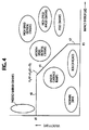
- a crash detection circuit of the present invention mounted in a vehicle for operating an inflatable restraint system, or what is called “airbags", when the vehicle encounters a crash.
- the crash detection circuit includes a semiconductor accelerometer 10 which consists of a strain gauge secured on a semiconductor substrate and makes use of the piezoelectric effect of the semiconductor to produce an accelerometer signal representative of the acceleration/deceleration of the vehicle when it is mechanically deformed upon the application of an impact force.
- an analog lowpass filter 11 is connected to the accelerometer 10 to cut off the frequency components of the accelerometer signal higher than twice the sampling frequency at which it is sampled and processed by subsequent processing circuitry.
- the lowpass-filtered signal is applied to a sampler 12 where it is sampled at, say, 1-ms intervals and fed into an analog-to-digital converter 13 where the sampled values are converted to a digitized signal.
- the digitized accelerometer signal is applied to a sliding window integrator 14 where digital samples are stored and a predetermined number of samples in a successive window of 90 milliseconds are integrated to produce a signal representative of the instantaneous velocity of the vehicle.
- the integration is repeated at 90-ms intervals to update the velocity value. It is found that under certain conditions vehicle deceleration continues excessively after the instant of crash, and the accelerometer signal becomes rich with low frequency components, producing a large negative integration value. Since the excessive negative value of the integrator would cause a delay in making a crash/non-crash decision, a limiter 15 is connected to the output of integrator 14 to prevent the velocity signal from going negative below a certain critical value. The output of limiter 15 is multiplied by a coefficient K1 in a multiplier 16 to produce a velocity parameter K1 ⁇ V.
- Vehicle crash can be considered as a plastic deformation of a composite of numerous resilient materials upon the application of impact. It is found that the deceleration signal contains unique frequency components when a vehicle experiences a crash.
- the frequency distribution of the deceleration signal that markedly shows a crash event varies depending on the type of vehicles.
- those frequency components having characteristic waveform fluctuations are extracted. These frequency components are considered to arise from different structural components of the vehicle as they are broken, bent and sheared upon crash impact.
- the characteristic frequency components are extracted from the range between 20 Hz and 200 Hz.
- the output of A/D converter 13 is applied to a bandpass filter 17 where the characteristic frequency components are extracted.
- the present invention evaluates the amount of a crash impact from the extracted frequency components.
- the bandpass filter 17 includes a first adder 30 to which the output of A/D converter 13 is applied.
- a tapped delay line comprising a series of one-sample delay elements, or delay-line taps 311 ⁇ 314 is connected to the output of adder 30 to produce a succession of tap signals.
- Coefficient multipliers 321 ⁇ 324 are connected respectively to the outputs of delay-line taps 311 ⁇ 31 4 for weighting the tap signals with tap-weight coefficients a1, -a2, a3 and -a4.
- the weighted tap signals are summed in adder 30 with the output of A/D converter 13 .
- the output of the first adder 30 is applied recursively to the tapped delay line and to a second adder 34 .
- a coefficient multiplier 33 is connected to the output of delay-line tap 31 2 to multiply the tap signal from delay unit 31 2 by "-2" and applied to adder 34 to which the output of delay-line tap 31 4 is also applied.
- the output of adder 34 is multiplied by a coefficient "b" in a multiplier 35 for delivery to a later stage.
- H(z) b(1 - z ⁇ 2)2/(1 - a1 z ⁇ 1 + a2 z ⁇ 2- a3 z ⁇ 3 + a4 z ⁇ 4)
- the impact energy of the vehicle during the zero- and 90-degree phase angles of the cosine curve can be approximated as being equal to the square value of the vehicle's speed variations. For this reason, the amplitude of the frequency components extracted by the bandpass filter 17 is squared in a squaring circuit 18 to produce a signal ⁇ E representative of the impact energy regardless of the polarities of the deceleration signal. The impact energy signal is then weighted by a coefficient K2 in a multiplier 19 to produce an impact parameter ⁇ E.
- the instantaneous speed parameter ⁇ V and impact parameter ⁇ E are supplied to a deployment decision circuit 20 for supplying a deployment signal to the airbags, not shown, in accordance with decision thresholds indicated in a crash discrimination map (Fig. 4) in which vehicle velocity ⁇ V is plotted as a function of impact energy ⁇ E.
- Fig. 4 a crash discrimination map in which vehicle velocity ⁇ V is plotted as a function of impact energy ⁇ E.
- different types of vehicle crash events and non-crash events are indicated in the shape of circles and ellipsis.
- the velocity and impact energy values falling within the boundary of any of these regions are those actually obtained by experiments at 30-ms after the instant of crash/non-crash event.
- a line 40 defines a first threshold R1 and is drawn between padded barrier crashes (in which the vehicle crashes with a barrier padded with shock absorbing material) and under-carriage bumps.
- a line 41 defines a second threshold R2 which is equal to the relation K1 ⁇ V + K2 ⁇ E drawn between frontal crash events and under-carriage bumps.
- a line 42 defines a third threshold R3 that separates pole crash events and rough roads.
- the decision circuit 20 produces a deployment signal when either of these thresholds is exceeded. Specifically, it includes comparators 21, 22 and 23 and an adder 24 . Comparator 21 compares the velocity parameter K1 ⁇ V with a reference voltage representing the first threshold R1 and produces a deployment signal when the velocity parameter exceeds the reference voltage.
- the velocity parameter K1 ⁇ V and impact energy parameter K2 ⁇ E are summed together by the adder 24 and compared by comparator 22 with a reference voltage representing the second threshold R2 to produce a deployment signal when the summed value exceeds the reference in a frontal crash event.
- Comparator 23 makes comparison between the impact energy K2 ⁇ E and a reference voltage representing the third threshold R3 and produces a deployment signal when the reference voltage is exceeded as the vehicle experiences a pole crash.
- the decision threshold R3 of pole crash events is set higher than any of impact energies which might be produced on rough roads, no false deployment signal is generated by the crash detector of the present invention in any rough road conditions.
- the impact energy exceeds threshold R3, while the velocity is lower than threshold R1 and the combined value of the velocity and the impact energy is also lower than threshold R2.
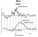
- limiter 15 is particularly useful for crash events where the velocity signal tends to go negative for an extended period of time and would otherwise cause decision delays.
- the output of limiter 15 goes positive earlier as indicated by broken lines than the output of integrator 14 does, contributing to the increases in the signal components which are significant for deployment decision.
- the modfied crash detection circuit comprises a 90-ms (long-term) sliding window integrator 40 , a limiter 41 and a multiply-by-K11 multiplier 42 to produce a long-term velocity signal ⁇ V1, and digital bandpass filter 46 , squaring circuit 47 and multiply-by-K2 multiplier 48 to produce an impact energy signal ⁇ E.
- long-term integrator 40 provides integration of the output of A/D converter 13 at 90-ms intervals and limiter 41 has the same lower critical value as limiter 15 .
- the modified embodiment differs from the previous embodiment by the inclusion of a short-term sliding window integrator 43 , a limiter 44 and a multiply-by-K12 multiplier 45 to produce a velocity signal ⁇ V2.
- the short-term integrator 43 provides integration of the output of A/D converter 13 at 30-ms intervals.
- the lower critical value of limiter 44 is slightly higher than that of limiter 41 .
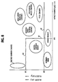
- the velocity signals ⁇ V1, ⁇ V2 and impact energy signal ⁇ E are supplied to a deployment decision circuit 50 which makes a deployment decision according to a decision map shown in Fig. 8.
- a line 60 defines a first threshold R'1 and is drawn between padded barrier crashes and under-carriage bumps.
- a horizontal line 62 corresponds to a second threshold R'2 and is drawn between frontal crash events and rough roads.
- a line 61 defines a third threshold R'3 that separates pole crash events and rough roads.
- the decision circuit 50 includes comparators 51, 52 and 53 .
- Comparator 51 makes a comparison between the velocity signal ⁇ V1 and a reference voltage corresponding to the first threshold R'1 and produces a deployment signal if the latter is exceeded.
- the output of comparator 51 is passed through an OR gate 55 to the airbags.
- Comparator 52 compares the velocity signal ⁇ V2 with a reference voltage corresponding to the second threshold R'2 and produces a deployment signal if the latter is exceeded.
- Comparator 53 compares the impact energy signal ⁇ E with a reference voltage corresponding to the third threshold R'3 and produces a deployment signal if the latter is exceeded when a padded barrier crash occurs.
- comparator 53 is applied to a pulse stretcher 56 where the it is stretched in duration by a monostable multivibrator 57 .
- An OR gate 58 is connected to the outputs of both comparator 53 and monostable multivibrator 57 so that the output of OR gate 58 goes high in quick response to the output signal of the comparator 53 .
- the outputs of comparator 52 and OR gate 58 are combined by an AND gate 54 whose output is coupled to OR gate 55 .
- AND gate 54 thus produces a deployment signal when the short-term velocity signal ⁇ V2 and the impact energy signal ⁇ E are time coincident with each other. Such coincidences occur when the vehicle experiences a frontal crash or a pole crash.
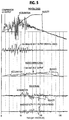
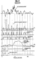
- Fig. 9 The waveforms of signals generated at various points of the embodiment of Fig. 7 in a frontal crash at 50 kmph are shown in Fig. 9.
- the output of squaring circuit 47 exceeds the threshold R'3 within the period of 10 milliseconds from the beginning of the crash, causing comparator 53 to produce an output pulse 70 , which is stretched by pulse stretcher 56 into a pulse 71 .
- the output of short-term integrator 43 exceeds the threshold R'2 and comparator 52 produces an output pulse 72 which coincides with the pulse 71 , producing a deployment pulse 73 at the output of AND gate 54 .
Abstract
Description
- The present invention relates to a vehicle crash detection apparatus for an inflatable occupant restraint system.
- A conventional crash detection apparatus for an inflatable occupant restraint system, or "airbags", makes use of an accelerometer and an offset integrator. The accelerometer generates upon crash impact a signal representative of the vehicle acceleration/deceleration, while the offset integrator subtracts the maximum acceleration value that is encountered during normal drive from the output of the accelerometer and integrates the subtracted acceleration signal over a preset time interval. The integrated signal is then compared with a threshold value and when the threshold is exceeded the restraint system is operated. Since the airbag must be fully deployed before the occupant is tilted 12.5 centimeters forwards when the vehicle crashes at a medium speed, and the airbag deployment time is approximately 30 milliseconds, there is a small amount of time left for the crash detection apparatus to make a crash/non-crash discrimination.
- While the prior art crash detection apparatus is useful for crash events where a sharp vehicle speed variation occurs upon impact, it fails to make a correct discrimination between rough roads and pole crashes where the initial impact on the vehicle is rather small.
- It is therefore an object of the present invention to provide precision vehicle crash detection capable of making a reliable discrimination between crash and non-crash events which are currently indistinguishable.
- The object of the present invention is obtained by extracting those frequency components of the output of the accelerometer which occur uniquely during a vehicle crash and using the extracted frequency components as a decision making factor.
- According to a first aspect of the present invention, the output signal from an accelerometer is integrated at intervals to derive a velocity signal. Those frequency components of the accelerometer signal which appear uniquely during the vehicle crash are extracted and the amplitude of the extracted components is squared to produce an impact energy signal. A decision is made on the velocity signal and the impact energy signal, and according to this decision, the occupant restraint system is operated. Preferably, the velocity signal is compared with a first threshold value and when it exceeds the first threshold value, the restraint system is operated. A sum of the velocity signal and the impact energy signal is produced and compared with a second threshold value, and the impact energy signal is compared with a third threshold value. The restraint system is operated when the sum exceeds the second threshold value or when the impact energy signal exceeds the third threshold value.
- According to a second aspect of the present invention, the accelerometer signal at longer intervals to produce a long-term velocity signal and at shorter intervals to produce a short-term velocity signal. Frequency components of the accelerometer signal which appear uniquely during the vehicle crash are extracted and the amplitude of the extracted components is squared to produce an impact energy signal. A decision is made on the long-term and short-term velocity signals and the impact energy signal, and the occupant restraint system is operated in accordance with the decision. Preferably, the long-term velocity signal is compared with a first threshold value and when it exceeds the first threshold value, the restraint system is operated. The short-term velocity signal and the impact energy signal are compared with a second and a third threshold value, respectively. The restraint system is operated when both of the short-term velocity signal and impact energy signal simultaneously exceed their respective threshold values.
- The present invention will be described in further detail with reference to the accompanying drawings, in which:
- Fig. 1 is a block diagram of a crash detection circuit according to one embodiment of the present invention;
- Fig. 2 is a block diagram of the bandpass filter of Fig. 1;
- Fig. 3 is a graphic representation of the frequency response of the bandpass filter;
- Fig. 4 is a crash/non-crash discrimination map associated with the embodiment of Fig. 1;
- Fig. 5 is a waveform diagram showing various waveforms appearing in Fig. 1 during frontal crash, padded barrier crash and rough road drive;
- Fig. 6 is a waveform diagram showing waveforms of the accelerometer, integrator and limiter in the case of an angle crash;
- Fig. 7 is block diagram of a crash detection circuit according to a modified embodiment of the present invention;
- Fig. 8 is a crash/non-crash discrimination map associated with the embodiment of Fig. 7; and
- Fig. 9 is a waveform diagram showing various waveforms appearing in Fig. 7 during a frontal crash.
- Referring now to Fig. 1, there is shown a crash detection circuit of the present invention mounted in a vehicle for operating an inflatable restraint system, or what is called "airbags", when the vehicle encounters a crash. The crash detection circuit includes a
semiconductor accelerometer 10 which consists of a strain gauge secured on a semiconductor substrate and makes use of the piezoelectric effect of the semiconductor to produce an accelerometer signal representative of the acceleration/deceleration of the vehicle when it is mechanically deformed upon the application of an impact force. - To allow digital processing of the accelerometer signal without foldover (aliasing) distortion, an
analog lowpass filter 11 is connected to theaccelerometer 10 to cut off the frequency components of the accelerometer signal higher than twice the sampling frequency at which it is sampled and processed by subsequent processing circuitry. The lowpass-filtered signal is applied to asampler 12 where it is sampled at, say, 1-ms intervals and fed into an analog-to-digital converter 13 where the sampled values are converted to a digitized signal. - The digitized accelerometer signal is applied to a
sliding window integrator 14 where digital samples are stored and a predetermined number of samples in a successive window of 90 milliseconds are integrated to produce a signal representative of the instantaneous velocity of the vehicle. The integration is repeated at 90-ms intervals to update the velocity value. It is found that under certain conditions vehicle deceleration continues excessively after the instant of crash, and the accelerometer signal becomes rich with low frequency components, producing a large negative integration value. Since the excessive negative value of the integrator would cause a delay in making a crash/non-crash decision, alimiter 15 is connected to the output ofintegrator 14 to prevent the velocity signal from going negative below a certain critical value. The output oflimiter 15 is multiplied by a coefficient K₁ in amultiplier 16 to produce a velocity parameter K₁ΔV. - Vehicle crash can be considered as a plastic deformation of a composite of numerous resilient materials upon the application of impact. It is found that the deceleration signal contains unique frequency components when a vehicle experiences a crash. The frequency distribution of the deceleration signal that markedly shows a crash event varies depending on the type of vehicles. According to the present invention, among the various waveforms that are superimposed on a first quarter wavelength of the fundamental frequency of the sinusoidal deceleration waveform generated upon impact those frequency components having characteristic waveform fluctuations are extracted. These frequency components are considered to arise from different structural components of the vehicle as they are broken, bent and sheared upon crash impact. Typically, the characteristic frequency components are extracted from the range between 20 Hz and 200 Hz. For this purpose, the output of A/
D converter 13 is applied to abandpass filter 17 where the characteristic frequency components are extracted. The present invention evaluates the amount of a crash impact from the extracted frequency components. - As shown in detail in Fig. 2, the
bandpass filter 17 includes afirst adder 30 to which the output of A/D converter 13 is applied. A tapped delay line comprising a series of one-sample delay elements, or delay-line taps 31₁∼31₄ is connected to the output ofadder 30 to produce a succession of tap signals.Coefficient multipliers 32₁∼32₄ are connected respectively to the outputs of delay-line taps 31₁∼31₄ for weighting the tap signals with tap-weight coefficients a₁, -a₂, a₃ and -a₄. The weighted tap signals are summed inadder 30 with the output of A/D converter 13. The output of thefirst adder 30 is applied recursively to the tapped delay line and to asecond adder 34. Acoefficient multiplier 33 is connected to the output of delay-line tap 31₂ to multiply the tap signal fromdelay unit 31² by "-2" and applied to adder 34 to which the output of delay-line tap 31₄ is also applied. The output ofadder 34 is multiplied by a coefficient "b" in amultiplier 35 for delivery to a later stage. The transfer function H(z) of thebandpass filter 17 is given by:

By choosing the tap-weight coefficients and the coefficient "b" as a₁ = 2.2979, a₂ = 1.9649, a₃ = 0.8732, a₄ = 0.2194, and b = 0.7012, thebandpass filter 17 has a passband of 20 Hz to 200 Hz as shown in Fig. 3. - Since the vehicle speed, upon impact, decays following a cosine curve, the impact energy of the vehicle during the zero- and 90-degree phase angles of the cosine curve can be approximated as being equal to the square value of the vehicle's speed variations. For this reason, the amplitude of the frequency components extracted by the
bandpass filter 17 is squared in asquaring circuit 18 to produce a signal ΔE representative of the impact energy regardless of the polarities of the deceleration signal. The impact energy signal is then weighted by a coefficient K₂ in amultiplier 19 to produce an impact parameter ΔE. - The instantaneous speed parameter ΔV and impact parameter ΔE are supplied to a
deployment decision circuit 20 for supplying a deployment signal to the airbags, not shown, in accordance with decision thresholds indicated in a crash discrimination map (Fig. 4) in which vehicle velocity ΔV is plotted as a function of impact energy ΔE. In Fig. 4, different types of vehicle crash events and non-crash events are indicated in the shape of circles and ellipsis. The velocity and impact energy values falling within the boundary of any of these regions are those actually obtained by experiments at 30-ms after the instant of crash/non-crash event. Aline 40 defines a first threshold R₁ and is drawn between padded barrier crashes (in which the vehicle crashes with a barrier padded with shock absorbing material) and under-carriage bumps. Aline 41 defines a second threshold R₂ which is equal to the relation
line 42 defines a third threshold R₃ that separates pole crash events and rough roads. Thedecision circuit 20 produces a deployment signal when either of these thresholds is exceeded. Specifically, it includescomparators adder 24.Comparator 21 compares the velocity parameter K₁ΔV with a reference voltage representing the first threshold R₁ and produces a deployment signal when the velocity parameter exceeds the reference voltage. This occurs when the vehicle experiences a padded barrier crash. The velocity parameter K₁ΔV and impact energy parameter K₂ΔE are summed together by theadder 24 and compared bycomparator 22 with a reference voltage representing the second threshold R₂ to produce a deployment signal when the summed value exceeds the reference in a frontal crash event. Comparator 23 makes comparison between the impact energy K₂ΔE and a reference voltage representing the third threshold R₃ and produces a deployment signal when the reference voltage is exceeded as the vehicle experiences a pole crash. - In the case of a frontal crash at 50 kilometer per hour (Fig. 5), both acceleration (G) and velocity (ΔV) rapidly rise on impact, and the sum of impact energy and velocity exceeds the threshold value R₂ of
comparator 22 within 10 milliseconds from the start of crash. In the case of a padded barrier crash at 30 kmph, the velocity (ΔV) exceeds the threshold R₁ ofcomparator 21 at about 80 milliseconds from the start of the crash. During a rough road drive, the velocity parameter is lower than threshold R₁ and thebandpass filter 17 produces a sharply rising output, but its amplitude is lower than threshold R₃. With prior art techniques, false decisions are often made in discriminating a rough road event from a pole crash event. Since the decision threshold R₃ of pole crash events is set higher than any of impact energies which might be produced on rough roads, no false deployment signal is generated by the crash detector of the present invention in any rough road conditions. In the case of pole crashes, the impact energy exceeds threshold R₃, while the velocity is lower than threshold R₁ and the combined value of the velocity and the impact energy is also lower than threshold R₂. - As illustrated in Fig. 6, the use of the
limiter 15 is particularly useful for crash events where the velocity signal tends to go negative for an extended period of time and would otherwise cause decision delays. The output oflimiter 15 goes positive earlier as indicated by broken lines than the output ofintegrator 14 does, contributing to the increases in the signal components which are significant for deployment decision. - The present invention is modified as shown in Fig. 7 which employs different decision thresholds from those used in the previous embodiment. Similar to the previous embodiment, the modfied crash detection circuit comprises a 90-ms (long-term) sliding
window integrator 40, alimiter 41 and a multiply-by-K₁₁ multiplier 42 to produce a long-term velocity signal ΔV₁, anddigital bandpass filter 46, squaringcircuit 47 and multiply-by-K₂ multiplier 48 to produce an impact energy signal ΔE. Similar to the previous embodiment, long-term integrator 40 provides integration of the output of A/D converter 13 at 90-ms intervals andlimiter 41 has the same lower critical value aslimiter 15. The modified embodiment differs from the previous embodiment by the inclusion of a short-term slidingwindow integrator 43, alimiter 44 and a multiply-by-K₁₂ multiplier 45 to produce a velocity signal ΔV₂. The short-term integrator 43 provides integration of the output of A/D converter 13 at 30-ms intervals. The lower critical value oflimiter 44 is slightly higher than that oflimiter 41. The velocity signals ΔV₁, ΔV₂ and impact energy signal ΔE are supplied to adeployment decision circuit 50 which makes a deployment decision according to a decision map shown in Fig. 8. - As illustrated in Fig. 8, a
line 60 defines a first threshold R'₁ and is drawn between padded barrier crashes and under-carriage bumps. Ahorizontal line 62 corresponds to a second threshold R'₂ and is drawn between frontal crash events and rough roads. Finally, aline 61 defines a third threshold R'₃ that separates pole crash events and rough roads. - Returning to Fig. 7, the
decision circuit 50 includescomparators Comparator 51 makes a comparison between the velocity signal ΔV₁ and a reference voltage corresponding to the first threshold R'₁ and produces a deployment signal if the latter is exceeded. The output ofcomparator 51 is passed through anOR gate 55 to the airbags.Comparator 52 compares the velocity signal ΔV₂ with a reference voltage corresponding to the second threshold R'₂ and produces a deployment signal if the latter is exceeded.Comparator 53 compares the impact energy signal ΔE with a reference voltage corresponding to the third threshold R'₃ and produces a deployment signal if the latter is exceeded when a padded barrier crash occurs. The output ofcomparator 53 is applied to apulse stretcher 56 where the it is stretched in duration by amonostable multivibrator 57. An ORgate 58 is connected to the outputs of bothcomparator 53 andmonostable multivibrator 57 so that the output ofOR gate 58 goes high in quick response to the output signal of thecomparator 53. The outputs ofcomparator 52 andOR gate 58 are combined by an ANDgate 54 whose output is coupled toOR gate 55. ANDgate 54 thus produces a deployment signal when the short-term velocity signal ΔV₂ and the impact energy signal ΔE are time coincident with each other. Such coincidences occur when the vehicle experiences a frontal crash or a pole crash. - The waveforms of signals generated at various points of the embodiment of Fig. 7 in a frontal crash at 50 kmph are shown in Fig. 9. The output of squaring
circuit 47 exceeds the threshold R'₃ within the period of 10 milliseconds from the beginning of the crash, causingcomparator 53 to produce anoutput pulse 70, which is stretched bypulse stretcher 56 into apulse 71. Immediately following the leading edge of thepulse 71, the output of short-term integrator 43 exceeds the threshold R'₂ andcomparator 52 produces anoutput pulse 72 which coincides with thepulse 71, producing adeployment pulse 73 at the output of ANDgate 54. - The foregoing description shows only preferred embodiments of the present invention. Various modifications are apparent to those skilled in the art without departing from the scope of the present invention which is only limited by the appended claims. For example, the digital circuitry connected to the output of A/
D converter 13 can be implemented with a digital signal processor. Therefore, the embodiments shown and described are only illustrative, not restrictive.
Claims (11)
- A crash detection apparatus adapted to be mounted on a vehicle for operating an inflatable occupant restraint system, comprising:
an accelerometer for producing an accelerometer signal representative of acceleration/deceleration of the vehicle during a vehicle crash;
integrator means for integrating said accelerometer signal at intervals and producing a velocity signal;
bandpass filter means for filtering a frequency range of said accelerometer signal which appears uniquely during said vehicle crash;
squaring means for squaring amplitude of the bandpass filtered accelerometer signal and producing an impact energy signal; and
decision means for producing a deployment signal in accordance with said velocity signal and said impact energy signal and applying said deployment signal to said occupant restraint system. - A crash detection apparatus as claimed in clam 1, wherein said decision means comprises:
first comparator means for comparing said velocity signal with a first threshold value and producing a first deployment signal when said velocity signal exceeds said first threshold value;
adder means for summing said velocity signal and said impact energy signal;
second comparator means for comparing the output of the adder means with a second threshold value and applying a second deployment signal to said restraint system when said output signal of the adder means exceeds said said second threshold value; and
third comparator means for comparing said impact energy signal with a third threshold value and applying a third deployment signal to said restraint system when said impact energy signal exceeds said third threshold value. - A crash detection apparatus as claimed in claim 1 or 2, further comprising limiter means for preventing the output signal of said integrator means from reducing below a predetermined negative level.
- A crash detection apparatus adapted to be mounted on a vehicle for operating an inflatable occupant restraint system, comprising:
an accelerometer for producing an accelerometer signal representative of acceleration/deceleration of the vehicle during a vehicle crash;
long-term integrator means for integrating said accelerometer signal at longer intervals and producing a long-term velocity signal;
short-term integrator means for integrating said accelerometer signal at shorter intervals and producing a short-term velocity signal;
bandpass filter means for filtering a frequency range of said accelerometer signal which appears uniquely during said vehicle crash;
squaring means for squaring amplitude of the bandpass filtered accelerometer signal and producing an impact energy signal; and
decision means for producing a deployment signal in accordance with said long-term and short-term velocity signals and said impact energy signal and applying said deployment signal to said occupant restraint system. - A crash detection apparatus as claimed in claim 4, wherein said decision means comprises:
first comparator means for comparing said long-term velocity signal with a first threshold value and applying a first deployment signal to said restraint system when said velocity signal exceeds said first threshold value;
second comparator means for comparing said short-term velocity signal with a second threshold value and producing an output signal when said short-term velocity signal exceeds said said second threshold value;
third comparator means for comparing said impact energy signal with a third threshold value and producing an output signal when said impact energy signal exceeds said third threshold value; and
coincidence detection means for applying a second deployment signal to said restraint system when there is a coincidence between the output signals of said second and third comparator means. - A crash detection apparatus as claimed in claim 4 or 5, further comprising first limiter means for preventing the output signal of said long-term integrator means from reducing below a first predetermined negative level and second limiter means for preventing the output signal of said short-term integrator means from reducing below a second predetermined negative level.
- A crash detection apparatus as claimed in claim 5 or 6, wherein said coincidence detection means includes;
means for stretching the duration of the output signal of said third comparator means; and
a coincidence gate for producing said second deployment signal when there is a coincidence between the stretched output signal of the third comparator means and the output signal of said second comparator means. - In an apparatus adapted to be mounted on a vehicle for operating an inflatable occupant restraint system, the apparatus comprising an accelerometer for producing an accelerometer signal representative of acceleration/deceleration of the vehicle during a vehicle crash, a method comprising the steps of;a) integrating said accelerometer signal at intervals and producing a velocity signal;b) extracting frequency components of said accelerometer signal which appear uniquely during said vehicle crash;c) squaring amplitude of the extracted frequency components and producing therefrom an impact energy signal; andd) operating said occupant restraint system in response to said velocity signal and said impact energy signal.
- A method as claimed in claim 8, wherein the step (d) comprises:d1) comparing said velocity signal with a first threshold value and operating said restraint system when said velocity signal exceeds said first threshold value;d2) producing a sum of said velocity signal and said impact energy signal;d3) comparing the sum with a second threshold value and operating said restraint system when said sum exceeds said said second threshold value; andd4) comparing said impact energy signal with a third threshold value and operating said restraint system when said impact energy signal exceeds said third threshold value.
- In an apparatus apparatus adapted to be mounted on a vehicle for operating an inflatable occupant restraint system, the apparatus comprising an accelerometer for producing an accelerometer signal representative of acceleration/deceleration of the vehicle during a vehicle crash, a method comprising the steps of:a) integrating said accelerometer signal at longer intervals and producing therefrom a long-term velocity signal;b) integrating said accelerometer signal at shorter intervals and producing therefrom a short-term velocity signal;c) extracting frequency components of said accelerometer signal which appear uniquely during said vehicle crash;d) squaring amplitude of the extracted frequency components and producing an impact energy signal; ande) operating said occupant restraint system in response to said long-term and short-term velocity signals and said impact energy signal.
- A method as claimed in claim 10, wherein the step (e) comprises:e1) comparing said long-term velocity signal with a first threshold value and operating said restraint system when said velocity signal exceeds said first threshold value;e2) comparing said short-term velocity signal with a second threshold value and comparing said impact energy signal with a third threshold value; ande3) operating said restraint system when the short-term velocity signal and said impact energy signal are simultaneously determined by the step (e2) as exceeding said second and third threshold values, respectively.
Applications Claiming Priority (6)
| Application Number | Priority Date | Filing Date | Title |
|---|---|---|---|
| JP250914/92 | 1992-09-21 | ||
| JP04250914A JP3118980B2 (en) | 1992-09-21 | 1992-09-21 | Vehicle collision determination device |
| JP315348/92 | 1992-11-25 | ||
| JP31534892 | 1992-11-25 | ||
| JP5114780A JP3055361B2 (en) | 1992-11-25 | 1993-05-17 | Vehicle collision determination method and collision determination device |
| JP114780/93 | 1993-05-17 |
Publications (3)
| Publication Number | Publication Date |
|---|---|
| EP0590476A2 true EP0590476A2 (en) | 1994-04-06 |
| EP0590476A3 EP0590476A3 (en) | 1994-09-07 |
| EP0590476B1 EP0590476B1 (en) | 1997-12-10 |
Family
ID=27312822
Family Applications (1)
| Application Number | Title | Priority Date | Filing Date |
|---|---|---|---|
| EP93115182A Expired - Lifetime EP0590476B1 (en) | 1992-09-21 | 1993-09-21 | Crash/non-crash discrimination using frequency components of acceleration uniquely generated upon crash impact |
Country Status (4)
| Country | Link |
|---|---|
| US (1) | US5436838A (en) |
| EP (1) | EP0590476B1 (en) |
| CA (1) | CA2106603C (en) |
| DE (1) | DE69315653T2 (en) |
Cited By (6)
| Publication number | Priority date | Publication date | Assignee | Title |
|---|---|---|---|---|
| US5498028A (en) * | 1994-01-04 | 1996-03-12 | Trw Inc. | Method and apparatus for controlling an actuatable restraining device |
| EP0709256A1 (en) * | 1994-10-31 | 1996-05-01 | Daewoo Electronics Co., Ltd | Method for judging collision with three directional accelerative signals and apparatus for performing the same |
| EP0739280A1 (en) * | 1994-10-25 | 1996-10-30 | Automotive Systems Laboratory Inc. | Crash discriminator responsive to early-crush and multiple-hit scenarios |
| WO1996039315A1 (en) * | 1995-06-06 | 1996-12-12 | Siemens Aktiengesellschaft | Control device for triggering a restraint system in a vehicle during a sideways-on collision |
| EP0844150A1 (en) * | 1996-11-20 | 1998-05-27 | Robert Bosch Gmbh | Method for generating crash signals |
| US6910711B1 (en) * | 1992-05-05 | 2005-06-28 | Automotive Technologies International, Inc. | Method for controlling deployment of an occupant protection device |
Families Citing this family (60)
| Publication number | Priority date | Publication date | Assignee | Title |
|---|---|---|---|---|
| US6199874B1 (en) | 1993-05-26 | 2001-03-13 | Cornell Research Foundation Inc. | Microelectromechanical accelerometer for automotive applications |
| US6149190A (en) * | 1993-05-26 | 2000-11-21 | Kionix, Inc. | Micromechanical accelerometer for automotive applications |
| US5835298A (en) * | 1996-08-16 | 1998-11-10 | Telxon Corporation | Hard drive protection system and method |
| JP2889119B2 (en) * | 1994-06-20 | 1999-05-10 | 三菱自動車工業株式会社 | Starting device for occupant protection device |
| JP3329080B2 (en) * | 1994-07-29 | 2002-09-30 | 日本電気株式会社 | Vehicle collision determination method and collision determination device |
| US5559699A (en) * | 1994-08-26 | 1996-09-24 | Automotive Systems Laboratory, Inc. | Matched filter for vehicle crash discrimination |
| US8280682B2 (en) | 2000-12-15 | 2012-10-02 | Tvipr, Llc | Device for monitoring movement of shipped goods |
| US7386401B2 (en) | 1994-11-21 | 2008-06-10 | Phatrat Technology, Llc | Helmet that reports impact information, and associated methods |
| US6266623B1 (en) | 1994-11-21 | 2001-07-24 | Phatrat Technology, Inc. | Sport monitoring apparatus for determining loft time, speed, power absorbed and other factors such as height |
| US5668740A (en) * | 1994-12-20 | 1997-09-16 | General Motors Corporation | Method for detecting a rough road surface |
| DE4445996C2 (en) * | 1994-12-22 | 2002-10-24 | Bosch Gmbh Robert | Restraint release procedures |
| GB2310303B (en) * | 1996-02-13 | 1999-07-28 | Autoliv Dev | Improvements in or relating to a crash detector arrangement |
| US6175299B1 (en) * | 1996-03-04 | 2001-01-16 | Delco Electronics Corporation | Analog signal processing system for determining airbag deployment |
| US5801619A (en) * | 1996-03-04 | 1998-09-01 | Delco Electronics Corp. | Analog signal processing system and decision logic for controlling airbag deployment |
| US5906393A (en) * | 1997-09-16 | 1999-05-25 | Trw Inc. | Occupant restraint system and control method with variable sense, sample, and determination rates |
| US6192849B1 (en) | 1999-06-18 | 2001-02-27 | Siemens Canada Limited | Manifold housing system |
| US6173224B1 (en) | 1998-07-17 | 2001-01-09 | Ford Global Technologies, Inc. | Occupant-restraint deployment method and system for automotive vehicle |
| US6129282A (en) * | 1998-07-20 | 2000-10-10 | Psc Scanning, Inc. | Rugged scanning subsystem for data reading |
| US6076028A (en) * | 1998-09-29 | 2000-06-13 | Veridian Engineering, Inc. | Method and apparatus for automatic vehicle event detection, characterization and reporting |
| US6272412B1 (en) | 1998-11-09 | 2001-08-07 | Ford Global Technologies, Inc. | Passive restraint control system for vehicles |
| CA2254538C (en) | 1998-11-26 | 2006-02-07 | Canpolar East Inc. | Collision deformation sensor for use in the crush zone of a vehicle |
| CA2254535C (en) | 1998-11-26 | 2003-10-28 | Canpolar East Inc. | Sensor for detection of acceleration and attitude within a vehicle |
| DE69910431T2 (en) * | 1998-12-15 | 2004-07-01 | Siemens Vdo Automotive Corporation, Auburn Hills | IMPACT DISCRIMINATOR FOR A RESTRAINT SYSTEM |
| US6729646B1 (en) * | 1999-02-25 | 2004-05-04 | Siemens Vdo Automotive Corporation | Method and system for controlling a vehicle occupant safety system based on crash severity |
| DE19917710A1 (en) * | 1999-04-20 | 2000-10-26 | Bosch Gmbh Robert | Procedure for formation of a triggering level for a vehicle restraining mechanism such as an airbag has a low pass filter through which the acceleration signal is passed so that the filtered signal can be compared with a threshold |
| KR20030031473A (en) | 2000-04-03 | 2003-04-21 | 지멘스 비디오 오토모티브 코포레이션 | Safing method for a vehicle occupant protection safety system |
| DE10025259C2 (en) * | 2000-05-22 | 2003-03-20 | Conti Temic Microelectronic | Method for generating a triggering algorithm for detecting a rollover for a security system in a motor vehicle |
| US6563761B1 (en) | 2000-11-02 | 2003-05-13 | Trw Inc. | Apparatus and method of vehicle occupant sensing using multiple ultrasonic frequencies |
| DE10059104C5 (en) * | 2000-11-28 | 2008-09-25 | Continental Automotive Gmbh | Occupant protection device and method for triggering decision |
| DE10160883B4 (en) * | 2001-12-12 | 2014-02-13 | Volkswagen Ag | Method and device for detecting the severity of a vehicle |
| JP4569114B2 (en) * | 2004-01-28 | 2010-10-27 | 株式会社デンソー | Occupant protection system and determination device |
| JP4168944B2 (en) * | 2004-01-28 | 2008-10-22 | 株式会社デンソー | Occupant protection system and determination device |
| US20050222801A1 (en) * | 2004-04-06 | 2005-10-06 | Thomas Wulff | System and method for monitoring a mobile computing product/arrangement |
| US7477974B2 (en) * | 2004-07-27 | 2009-01-13 | Robert Bosch Gmbh | Vehicle restraint device control method and apparatus using dynamically determined threshold |
| US8186711B2 (en) * | 2004-08-17 | 2012-05-29 | Robert Bosch Gmbh | Separation of abuse conditions and crash events to control occupant restraint devices |
| US7822513B2 (en) * | 2005-07-27 | 2010-10-26 | Symbol Technologies, Inc. | System and method for monitoring a mobile computing product/arrangement |
| WO2007047889A2 (en) * | 2005-10-18 | 2007-04-26 | Phatrat Technology, Llc | Shoe wear-out sensor, body-bar sensing system, unitless activity assessment and associated methods |
| US8073984B2 (en) | 2006-05-22 | 2011-12-06 | Apple Inc. | Communication protocol for use with portable electronic devices |
| US7643895B2 (en) | 2006-05-22 | 2010-01-05 | Apple Inc. | Portable media device with workout support |
| US9137309B2 (en) | 2006-05-22 | 2015-09-15 | Apple Inc. | Calibration techniques for activity sensing devices |
| US20070271116A1 (en) | 2006-05-22 | 2007-11-22 | Apple Computer, Inc. | Integrated media jukebox and physiologic data handling application |
| US20070297028A1 (en) * | 2006-06-21 | 2007-12-27 | Thomas Wulff | System and device for monitoring a computing device |
| US8594742B2 (en) * | 2006-06-21 | 2013-11-26 | Symbol Technologies, Inc. | System and method for monitoring a mobile device |
| DE102006038842B4 (en) | 2006-08-18 | 2019-06-13 | Robert Bosch Gmbh | Method and device for controlling personal protective equipment |
| US7913297B2 (en) | 2006-08-30 | 2011-03-22 | Apple Inc. | Pairing of wireless devices using a wired medium |
| US7813715B2 (en) | 2006-08-30 | 2010-10-12 | Apple Inc. | Automated pairing of wireless accessories with host devices |
| AU2007321749A1 (en) * | 2006-11-15 | 2008-05-22 | Radio Terminal Systems Pty Ltd | Vehicle movement processing system |
| US7698101B2 (en) | 2007-03-07 | 2010-04-13 | Apple Inc. | Smart garment |
| DE102007029582A1 (en) * | 2007-06-26 | 2009-01-08 | GM Global Technology Operations, Inc., Detroit | Motor vehicle roof |
| DE102008003339A1 (en) * | 2008-01-07 | 2009-07-09 | Robert Bosch Gmbh | Method and control device for controlling personal protective equipment for a vehicle |
| JP5329194B2 (en) | 2008-12-09 | 2013-10-30 | タカタ株式会社 | Collision determination system, occupant restraint system, vehicle |
| KR101081070B1 (en) * | 2009-10-07 | 2011-11-07 | 한국과학기술원 | Impact signal processor for the front impact acceleration sensor |
| US8751113B2 (en) | 2010-05-12 | 2014-06-10 | Trw Automotive U.S. Llc | Method and apparatus for detecting pedestrian vehicle impact |
| US20130079973A1 (en) * | 2011-09-24 | 2013-03-28 | Taif University | System for Communicating A Vehicle Position and Speed During Accident |
| US9855915B2 (en) | 2012-05-22 | 2018-01-02 | Trw Automotive U.S. Llc | Hybrid method and apparatus for detecting a vehicle/pedestrian impact |
| GB201307980D0 (en) | 2013-05-02 | 2013-06-12 | Redtail Telematics Ltd | Method, apparatus and computer program for detecting collision |
| JP6042308B2 (en) | 2013-10-29 | 2016-12-14 | 本田技研工業株式会社 | Vehicle collision determination device |
| DE102014207302A1 (en) * | 2014-04-16 | 2015-10-22 | Robert Bosch Gmbh | Method and device for switching off at least one ignition output stage for a squib of a pyrotechnic protective agent for a vehicle |
| US9787407B1 (en) | 2016-03-16 | 2017-10-10 | Google Inc. | Fading mitigation of the turbulent channel based on polarization diversity in coherent optical receivers |
| US11117781B2 (en) * | 2018-05-02 | 2021-09-14 | Otis Elevator Company | Vertical bounce detection and mitigation |
Citations (3)
| Publication number | Priority date | Publication date | Assignee | Title |
|---|---|---|---|---|
| WO1990009298A1 (en) * | 1989-02-18 | 1990-08-23 | Robert Bosch Gmbh | Process for releasing restraining means |
| US5109341A (en) * | 1989-11-03 | 1992-04-28 | Trw Vehicle Safety Systems Inc. | Method and apparatus for sensing a vehicle crash in the frequency domain |
| DE4117811A1 (en) * | 1991-05-31 | 1992-12-03 | Messerschmitt Boelkow Blohm | Motor vehicle impact detection method for activating occupant safety system - measuring acceleration and deceleration, integrating, subtracting previous speed value and comparing with threshold |
Family Cites Families (10)
| Publication number | Priority date | Publication date | Assignee | Title |
|---|---|---|---|---|
| CA2048678C (en) * | 1989-03-20 | 1997-01-07 | Jurgen Eigler | Control device for a passenger retaining and/or protective system for vehicles |
| JPH02270656A (en) * | 1989-04-12 | 1990-11-05 | Zexel Corp | Controller of safety device for vehicle |
| US5216607A (en) * | 1989-05-30 | 1993-06-01 | Trw Vehicle Safety Systems Inc. | Method and apparatus for sensing a vehicle crash using energy and velocity as measures of crash violence |
| JPH03114944A (en) * | 1989-09-28 | 1991-05-16 | Nissan Motor Co Ltd | Air bag control device |
| US5073860A (en) * | 1989-11-07 | 1991-12-17 | Trw Vehicle Safety Systems Inc. | Method and apparatus for sensing a vehicle crash in real time using frequency domain analysis |
| JP2543839B2 (en) * | 1990-01-29 | 1996-10-16 | センサー・テクノロジー株式会社 | Collision sensor |
| JP2905240B2 (en) * | 1990-02-07 | 1999-06-14 | アスコ株式会社 | Control system for vehicle safety equipment |
| US5036467A (en) * | 1990-04-04 | 1991-07-30 | Trw Vehicle Safety Systems Inc. | Method and apparatus for sensing a vehicle crash in real time using a frequency domain integration and summation algorithm |
| US5065322A (en) * | 1990-04-04 | 1991-11-12 | Trw Vehicle Safety Systems Inc. | Method and apparatus for sensing a vehicle crash in real time using a frequency domain summation algorithm |
| US5164901A (en) * | 1991-12-05 | 1992-11-17 | Trw Vehicle Safety Systems Inc. | Method and apparatus for testing a vehicle occupant restraint system |
-
1993
- 1993-09-21 DE DE69315653T patent/DE69315653T2/en not_active Expired - Lifetime
- 1993-09-21 US US08/124,229 patent/US5436838A/en not_active Expired - Lifetime
- 1993-09-21 EP EP93115182A patent/EP0590476B1/en not_active Expired - Lifetime
- 1993-09-21 CA CA002106603A patent/CA2106603C/en not_active Expired - Lifetime
Patent Citations (3)
| Publication number | Priority date | Publication date | Assignee | Title |
|---|---|---|---|---|
| WO1990009298A1 (en) * | 1989-02-18 | 1990-08-23 | Robert Bosch Gmbh | Process for releasing restraining means |
| US5109341A (en) * | 1989-11-03 | 1992-04-28 | Trw Vehicle Safety Systems Inc. | Method and apparatus for sensing a vehicle crash in the frequency domain |
| DE4117811A1 (en) * | 1991-05-31 | 1992-12-03 | Messerschmitt Boelkow Blohm | Motor vehicle impact detection method for activating occupant safety system - measuring acceleration and deceleration, integrating, subtracting previous speed value and comparing with threshold |
Non-Patent Citations (1)
| Title |
|---|
| SAE International P233, October 1990, US, Electronic Crash Sensor for Restraint Systems; pages 169-177 * |
Cited By (9)
| Publication number | Priority date | Publication date | Assignee | Title |
|---|---|---|---|---|
| US6910711B1 (en) * | 1992-05-05 | 2005-06-28 | Automotive Technologies International, Inc. | Method for controlling deployment of an occupant protection device |
| US5498028A (en) * | 1994-01-04 | 1996-03-12 | Trw Inc. | Method and apparatus for controlling an actuatable restraining device |
| EP0739280A1 (en) * | 1994-10-25 | 1996-10-30 | Automotive Systems Laboratory Inc. | Crash discriminator responsive to early-crush and multiple-hit scenarios |
| EP0739280A4 (en) * | 1994-10-25 | 1997-02-26 | Automotive Systems Lab | Crash discriminator responsive to early-crush and multiple-hit scenarios |
| EP0709256A1 (en) * | 1994-10-31 | 1996-05-01 | Daewoo Electronics Co., Ltd | Method for judging collision with three directional accelerative signals and apparatus for performing the same |
| WO1996039315A1 (en) * | 1995-06-06 | 1996-12-12 | Siemens Aktiengesellschaft | Control device for triggering a restraint system in a vehicle during a sideways-on collision |
| US6243632B1 (en) | 1995-06-06 | 2001-06-05 | Siemens Aktiengesellschaft | Control configuration for tripping a restraint device in a vehicle in the case of a side-impact collision |
| EP0844150A1 (en) * | 1996-11-20 | 1998-05-27 | Robert Bosch Gmbh | Method for generating crash signals |
| US6959244B1 (en) | 1996-11-20 | 2005-10-25 | Robert Bosch Gmbh | Process for generating collision signals |
Also Published As
| Publication number | Publication date |
|---|---|
| CA2106603C (en) | 1997-09-16 |
| EP0590476B1 (en) | 1997-12-10 |
| DE69315653D1 (en) | 1998-01-22 |
| CA2106603A1 (en) | 1994-03-22 |
| DE69315653T2 (en) | 1998-04-02 |
| US5436838A (en) | 1995-07-25 |
| EP0590476A3 (en) | 1994-09-07 |
Similar Documents
| Publication | Publication Date | Title |
|---|---|---|
| EP0590476A2 (en) | Crash/non-crash discrimination using frequency components of acceleration uniquely generated upon crash impact | |
| US5758301A (en) | Vehicle crash detection for implementation with low cost microprocessor | |
| EP0498312A1 (en) | Vehicle collision detecting apparatus | |
| US5337238A (en) | System and method for actuating vehicle safety device using damped measures | |
| KR0142857B1 (en) | Starting device and starting method of vehicle safety device | |
| JP2543839B2 (en) | Collision sensor | |
| EP0427398A2 (en) | Apparatus and method employing multiple crash evaluation algorithms for actuating a restraint system in a passenger vehicle | |
| US5519613A (en) | System and method for discriminating short-period crashes | |
| US5563791A (en) | Envelope detector useful in crash discrimination | |
| US6453225B1 (en) | Method for establishing a release criterion for restraining means | |
| US5541842A (en) | System and method for adjusting accumulated crash-discrimination measures based on crash progress | |
| DE102008005526A1 (en) | Method and control device for controlling personal protective equipment for a vehicle | |
| JP3289612B2 (en) | Vehicle collision determination method and collision determination device | |
| JP3289583B2 (en) | Vehicle collision determination method and collision determination device | |
| JP3118980B2 (en) | Vehicle collision determination device | |
| EP0782514B1 (en) | Method for damping crash-discrimination measures | |
| US8386130B2 (en) | Occupant protection device | |
| JP2761800B2 (en) | Vehicle collision determination device | |
| JP3314651B2 (en) | Method and apparatus for determining side collision of vehicle | |
| JP3870326B2 (en) | System and method for reducing collision discrimination errors | |
| JPH0478640A (en) | Operating device for passenger protecting device | |
| JP2925455B2 (en) | Airbag collision calculation device | |
| JPH08521B2 (en) | Vehicle occupant protection device | |
| JPH07304412A (en) | Air bag collision computing device | |
| JPH07144602A (en) | Collision sensor |
Legal Events
| Date | Code | Title | Description |
|---|---|---|---|
| PUAI | Public reference made under article 153(3) epc to a published international application that has entered the european phase |
Free format text: ORIGINAL CODE: 0009012 |
|
| AK | Designated contracting states |
Kind code of ref document: A2 Designated state(s): DE FR GB |
|
| PUAL | Search report despatched |
Free format text: ORIGINAL CODE: 0009013 |
|
| AK | Designated contracting states |
Kind code of ref document: A3 Designated state(s): DE FR GB |
|
| 17P | Request for examination filed |
Effective date: 19940727 |
|
| 17Q | First examination report despatched |
Effective date: 19951129 |
|
| GRAG | Despatch of communication of intention to grant |
Free format text: ORIGINAL CODE: EPIDOS AGRA |
|
| GRAH | Despatch of communication of intention to grant a patent |
Free format text: ORIGINAL CODE: EPIDOS IGRA |
|
| GRAH | Despatch of communication of intention to grant a patent |
Free format text: ORIGINAL CODE: EPIDOS IGRA |
|
| GRAA | (expected) grant |
Free format text: ORIGINAL CODE: 0009210 |
|
| AK | Designated contracting states |
Kind code of ref document: B1 Designated state(s): DE FR GB |
|
| REF | Corresponds to: |
Ref document number: 69315653 Country of ref document: DE Date of ref document: 19980122 |
|
| ET | Fr: translation filed | ||
| PLBE | No opposition filed within time limit |
Free format text: ORIGINAL CODE: 0009261 |
|
| STAA | Information on the status of an ep patent application or granted ep patent |
Free format text: STATUS: NO OPPOSITION FILED WITHIN TIME LIMIT |
|
| 26N | No opposition filed | ||
| REG | Reference to a national code |
Ref country code: GB Ref legal event code: IF02 |
|
| REG | Reference to a national code |
Ref country code: GB Ref legal event code: 732E |
|
| REG | Reference to a national code |
Ref country code: FR Ref legal event code: TP |
|
| PGFP | Annual fee paid to national office [announced via postgrant information from national office to epo] |
Ref country code: GB Payment date: 20120919 Year of fee payment: 20 |
|
| PGFP | Annual fee paid to national office [announced via postgrant information from national office to epo] |
Ref country code: DE Payment date: 20120919 Year of fee payment: 20 Ref country code: FR Payment date: 20120926 Year of fee payment: 20 |
|
| REG | Reference to a national code |
Ref country code: DE Ref legal event code: R071 Ref document number: 69315653 Country of ref document: DE |
|
| REG | Reference to a national code |
Ref country code: GB Ref legal event code: PE20 Expiry date: 20130920 |
|
| PG25 | Lapsed in a contracting state [announced via postgrant information from national office to epo] |
Ref country code: DE Free format text: LAPSE BECAUSE OF EXPIRATION OF PROTECTION Effective date: 20130924 |
|
| PG25 | Lapsed in a contracting state [announced via postgrant information from national office to epo] |
Ref country code: GB Free format text: LAPSE BECAUSE OF EXPIRATION OF PROTECTION Effective date: 20130920 |