EP0590873A1 - An arrangement for laser bonding - Google Patents
An arrangement for laser bonding Download PDFInfo
- Publication number
- EP0590873A1 EP0590873A1 EP93307507A EP93307507A EP0590873A1 EP 0590873 A1 EP0590873 A1 EP 0590873A1 EP 93307507 A EP93307507 A EP 93307507A EP 93307507 A EP93307507 A EP 93307507A EP 0590873 A1 EP0590873 A1 EP 0590873A1
- Authority
- EP
- European Patent Office
- Prior art keywords
- piece part
- laser
- arrangement
- attachment site
- concentrating
- Prior art date
- Legal status (The legal status is an assumption and is not a legal conclusion. Google has not performed a legal analysis and makes no representation as to the accuracy of the status listed.)
- Granted
Links
Images

Classifications
-
- B—PERFORMING OPERATIONS; TRANSPORTING
- B23—MACHINE TOOLS; METAL-WORKING NOT OTHERWISE PROVIDED FOR
- B23K—SOLDERING OR UNSOLDERING; WELDING; CLADDING OR PLATING BY SOLDERING OR WELDING; CUTTING BY APPLYING HEAT LOCALLY, e.g. FLAME CUTTING; WORKING BY LASER BEAM
- B23K26/00—Working by laser beam, e.g. welding, cutting or boring
- B23K26/02—Positioning or observing the workpiece, e.g. with respect to the point of impact; Aligning, aiming or focusing the laser beam
- B23K26/06—Shaping the laser beam, e.g. by masks or multi-focusing
- B23K26/064—Shaping the laser beam, e.g. by masks or multi-focusing by means of optical elements, e.g. lenses, mirrors or prisms
- B23K26/0643—Shaping the laser beam, e.g. by masks or multi-focusing by means of optical elements, e.g. lenses, mirrors or prisms comprising mirrors
-
- B—PERFORMING OPERATIONS; TRANSPORTING
- B23—MACHINE TOOLS; METAL-WORKING NOT OTHERWISE PROVIDED FOR
- B23K—SOLDERING OR UNSOLDERING; WELDING; CLADDING OR PLATING BY SOLDERING OR WELDING; CUTTING BY APPLYING HEAT LOCALLY, e.g. FLAME CUTTING; WORKING BY LASER BEAM
- B23K26/00—Working by laser beam, e.g. welding, cutting or boring
- B23K26/02—Positioning or observing the workpiece, e.g. with respect to the point of impact; Aligning, aiming or focusing the laser beam
- B23K26/06—Shaping the laser beam, e.g. by masks or multi-focusing
- B23K26/064—Shaping the laser beam, e.g. by masks or multi-focusing by means of optical elements, e.g. lenses, mirrors or prisms
- B23K26/0648—Shaping the laser beam, e.g. by masks or multi-focusing by means of optical elements, e.g. lenses, mirrors or prisms comprising lenses
-
- B—PERFORMING OPERATIONS; TRANSPORTING
- B23—MACHINE TOOLS; METAL-WORKING NOT OTHERWISE PROVIDED FOR
- B23K—SOLDERING OR UNSOLDERING; WELDING; CLADDING OR PLATING BY SOLDERING OR WELDING; CUTTING BY APPLYING HEAT LOCALLY, e.g. FLAME CUTTING; WORKING BY LASER BEAM
- B23K26/00—Working by laser beam, e.g. welding, cutting or boring
- B23K26/02—Positioning or observing the workpiece, e.g. with respect to the point of impact; Aligning, aiming or focusing the laser beam
- B23K26/06—Shaping the laser beam, e.g. by masks or multi-focusing
- B23K26/0665—Shaping the laser beam, e.g. by masks or multi-focusing by beam condensation on the workpiece, e.g. for focusing
-
- B—PERFORMING OPERATIONS; TRANSPORTING
- B29—WORKING OF PLASTICS; WORKING OF SUBSTANCES IN A PLASTIC STATE IN GENERAL
- B29C—SHAPING OR JOINING OF PLASTICS; SHAPING OF MATERIAL IN A PLASTIC STATE, NOT OTHERWISE PROVIDED FOR; AFTER-TREATMENT OF THE SHAPED PRODUCTS, e.g. REPAIRING
- B29C65/00—Joining or sealing of preformed parts, e.g. welding of plastics materials; Apparatus therefor
- B29C65/02—Joining or sealing of preformed parts, e.g. welding of plastics materials; Apparatus therefor by heating, with or without pressure
- B29C65/14—Joining or sealing of preformed parts, e.g. welding of plastics materials; Apparatus therefor by heating, with or without pressure using wave energy, i.e. electromagnetic radiation, or particle radiation
- B29C65/16—Laser beams
- B29C65/1629—Laser beams characterised by the way of heating the interface
- B29C65/1635—Laser beams characterised by the way of heating the interface at least passing through one of the parts to be joined, i.e. laser transmission welding
- B29C65/1638—Laser beams characterised by the way of heating the interface at least passing through one of the parts to be joined, i.e. laser transmission welding focusing the laser beam on the interface
-
- B—PERFORMING OPERATIONS; TRANSPORTING
- B29—WORKING OF PLASTICS; WORKING OF SUBSTANCES IN A PLASTIC STATE IN GENERAL
- B29C—SHAPING OR JOINING OF PLASTICS; SHAPING OF MATERIAL IN A PLASTIC STATE, NOT OTHERWISE PROVIDED FOR; AFTER-TREATMENT OF THE SHAPED PRODUCTS, e.g. REPAIRING
- B29C65/00—Joining or sealing of preformed parts, e.g. welding of plastics materials; Apparatus therefor
- B29C65/02—Joining or sealing of preformed parts, e.g. welding of plastics materials; Apparatus therefor by heating, with or without pressure
- B29C65/14—Joining or sealing of preformed parts, e.g. welding of plastics materials; Apparatus therefor by heating, with or without pressure using wave energy, i.e. electromagnetic radiation, or particle radiation
- B29C65/16—Laser beams
- B29C65/1687—Laser beams making use of light guides
- B29C65/169—Laser beams making use of light guides being a part of the joined article
- B29C65/1693—Laser beams making use of light guides being a part of the joined article in the form of a cavity
-
- B—PERFORMING OPERATIONS; TRANSPORTING
- B29—WORKING OF PLASTICS; WORKING OF SUBSTANCES IN A PLASTIC STATE IN GENERAL
- B29C—SHAPING OR JOINING OF PLASTICS; SHAPING OF MATERIAL IN A PLASTIC STATE, NOT OTHERWISE PROVIDED FOR; AFTER-TREATMENT OF THE SHAPED PRODUCTS, e.g. REPAIRING
- B29C66/00—General aspects of processes or apparatus for joining preformed parts
- B29C66/01—General aspects dealing with the joint area or with the area to be joined
- B29C66/05—Particular design of joint configurations
- B29C66/10—Particular design of joint configurations particular design of the joint cross-sections
- B29C66/11—Joint cross-sections comprising a single joint-segment, i.e. one of the parts to be joined comprising a single joint-segment in the joint cross-section
- B29C66/112—Single lapped joints
- B29C66/1122—Single lap to lap joints, i.e. overlap joints
-
- B—PERFORMING OPERATIONS; TRANSPORTING
- B29—WORKING OF PLASTICS; WORKING OF SUBSTANCES IN A PLASTIC STATE IN GENERAL
- B29C—SHAPING OR JOINING OF PLASTICS; SHAPING OF MATERIAL IN A PLASTIC STATE, NOT OTHERWISE PROVIDED FOR; AFTER-TREATMENT OF THE SHAPED PRODUCTS, e.g. REPAIRING
- B29C66/00—General aspects of processes or apparatus for joining preformed parts
- B29C66/01—General aspects dealing with the joint area or with the area to be joined
- B29C66/05—Particular design of joint configurations
- B29C66/10—Particular design of joint configurations particular design of the joint cross-sections
- B29C66/13—Single flanged joints; Fin-type joints; Single hem joints; Edge joints; Interpenetrating fingered joints; Other specific particular designs of joint cross-sections not provided for in groups B29C66/11 - B29C66/12
- B29C66/131—Single flanged joints, i.e. one of the parts to be joined being rigid and flanged in the joint area
-
- B—PERFORMING OPERATIONS; TRANSPORTING
- B29—WORKING OF PLASTICS; WORKING OF SUBSTANCES IN A PLASTIC STATE IN GENERAL
- B29C—SHAPING OR JOINING OF PLASTICS; SHAPING OF MATERIAL IN A PLASTIC STATE, NOT OTHERWISE PROVIDED FOR; AFTER-TREATMENT OF THE SHAPED PRODUCTS, e.g. REPAIRING
- B29C66/00—General aspects of processes or apparatus for joining preformed parts
- B29C66/01—General aspects dealing with the joint area or with the area to be joined
- B29C66/05—Particular design of joint configurations
- B29C66/20—Particular design of joint configurations particular design of the joint lines, e.g. of the weld lines
- B29C66/23—Particular design of joint configurations particular design of the joint lines, e.g. of the weld lines said joint lines being multiple and parallel or being in the form of tessellations
- B29C66/232—Particular design of joint configurations particular design of the joint lines, e.g. of the weld lines said joint lines being multiple and parallel or being in the form of tessellations said joint lines being multiple and parallel, i.e. the joint being formed by several parallel joint lines
-
- B—PERFORMING OPERATIONS; TRANSPORTING
- B29—WORKING OF PLASTICS; WORKING OF SUBSTANCES IN A PLASTIC STATE IN GENERAL
- B29C—SHAPING OR JOINING OF PLASTICS; SHAPING OF MATERIAL IN A PLASTIC STATE, NOT OTHERWISE PROVIDED FOR; AFTER-TREATMENT OF THE SHAPED PRODUCTS, e.g. REPAIRING
- B29C66/00—General aspects of processes or apparatus for joining preformed parts
- B29C66/40—General aspects of joining substantially flat articles, e.g. plates, sheets or web-like materials; Making flat seams in tubular or hollow articles; Joining single elements to substantially flat surfaces
- B29C66/41—Joining substantially flat articles ; Making flat seams in tubular or hollow articles
- B29C66/45—Joining of substantially the whole surface of the articles
-
- B—PERFORMING OPERATIONS; TRANSPORTING
- B29—WORKING OF PLASTICS; WORKING OF SUBSTANCES IN A PLASTIC STATE IN GENERAL
- B29C—SHAPING OR JOINING OF PLASTICS; SHAPING OF MATERIAL IN A PLASTIC STATE, NOT OTHERWISE PROVIDED FOR; AFTER-TREATMENT OF THE SHAPED PRODUCTS, e.g. REPAIRING
- B29C66/00—General aspects of processes or apparatus for joining preformed parts
- B29C66/01—General aspects dealing with the joint area or with the area to be joined
- B29C66/05—Particular design of joint configurations
- B29C66/302—Particular design of joint configurations the area to be joined comprising melt initiators
- B29C66/3022—Particular design of joint configurations the area to be joined comprising melt initiators said melt initiators being integral with at least one of the parts to be joined
- B29C66/30223—Particular design of joint configurations the area to be joined comprising melt initiators said melt initiators being integral with at least one of the parts to be joined said melt initiators being rib-like
-
- B—PERFORMING OPERATIONS; TRANSPORTING
- B29—WORKING OF PLASTICS; WORKING OF SUBSTANCES IN A PLASTIC STATE IN GENERAL
- B29C—SHAPING OR JOINING OF PLASTICS; SHAPING OF MATERIAL IN A PLASTIC STATE, NOT OTHERWISE PROVIDED FOR; AFTER-TREATMENT OF THE SHAPED PRODUCTS, e.g. REPAIRING
- B29C66/00—General aspects of processes or apparatus for joining preformed parts
- B29C66/40—General aspects of joining substantially flat articles, e.g. plates, sheets or web-like materials; Making flat seams in tubular or hollow articles; Joining single elements to substantially flat surfaces
- B29C66/41—Joining substantially flat articles ; Making flat seams in tubular or hollow articles
- B29C66/43—Joining a relatively small portion of the surface of said articles
-
- B—PERFORMING OPERATIONS; TRANSPORTING
- B29—WORKING OF PLASTICS; WORKING OF SUBSTANCES IN A PLASTIC STATE IN GENERAL
- B29K—INDEXING SCHEME ASSOCIATED WITH SUBCLASSES B29B, B29C OR B29D, RELATING TO MOULDING MATERIALS OR TO MATERIALS FOR MOULDS, REINFORCEMENTS, FILLERS OR PREFORMED PARTS, e.g. INSERTS
- B29K2705/00—Use of metals, their alloys or their compounds, for preformed parts, e.g. for inserts
-
- B—PERFORMING OPERATIONS; TRANSPORTING
- B29—WORKING OF PLASTICS; WORKING OF SUBSTANCES IN A PLASTIC STATE IN GENERAL
- B29K—INDEXING SCHEME ASSOCIATED WITH SUBCLASSES B29B, B29C OR B29D, RELATING TO MOULDING MATERIALS OR TO MATERIALS FOR MOULDS, REINFORCEMENTS, FILLERS OR PREFORMED PARTS, e.g. INSERTS
- B29K2995/00—Properties of moulding materials, reinforcements, fillers, preformed parts or moulds
- B29K2995/0018—Properties of moulding materials, reinforcements, fillers, preformed parts or moulds having particular optical properties, e.g. fluorescent or phosphorescent
- B29K2995/0025—Opaque
-
- B—PERFORMING OPERATIONS; TRANSPORTING
- B29—WORKING OF PLASTICS; WORKING OF SUBSTANCES IN A PLASTIC STATE IN GENERAL
- B29K—INDEXING SCHEME ASSOCIATED WITH SUBCLASSES B29B, B29C OR B29D, RELATING TO MOULDING MATERIALS OR TO MATERIALS FOR MOULDS, REINFORCEMENTS, FILLERS OR PREFORMED PARTS, e.g. INSERTS
- B29K2995/00—Properties of moulding materials, reinforcements, fillers, preformed parts or moulds
- B29K2995/0018—Properties of moulding materials, reinforcements, fillers, preformed parts or moulds having particular optical properties, e.g. fluorescent or phosphorescent
- B29K2995/0026—Transparent
- B29K2995/0027—Transparent for light outside the visible spectrum
Definitions
- the present invention relates to arrangements for laser bonding.
- first and second metallic components may be joined along a weld path, with the beam focused by a low turbulent flow of an inert shielding gas along a portion of the path.
- the material used to form the piece part (plastic or metal, for example) is opaque to the optical radiation and the radiation must therefore impinge the material from the side of the point of contact. This limitation is considered to further complicate and increase the cost of laser welding systems.
- the present invention which relates to laser bonding and, more particularly, to a scheme for improving the efficiency of laser bonding.
- At least one piece part is formed to include predefined features which concentrate the optical radiation toward predetermined locations which are to be joined.
- the piece part itself may be formed of a material which is opaque to the wavelength of optical radiation.
- a first piece part may be formed to include at least one aperture of a geometry (e.g., conical) which will provide concentration of the laser radiation at a predetermined location.
- a geometry e.g., conical
- a first piece part may be formed of a transparent material and include concentrating means, for example, an integral lens, to concentrate the radiation at the predetermined location.
- an absorbing material such as an epoxy may be used at the interface between piece parts to absorb the radiation and become heated.
- a first piece part may be formed to including diffraction means for concentrating the radiation near the location where the piece parts are to be joined.
- An exemplary embodiment of the present invention may utilize conical apertures, with the apex of the cone located at or near the joining location.
- the apertures may comprise a parabolic shape, thus providing heating at a number of focii, creating a plurality of joints.
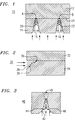
- FIG. 1 illustrates an exemplary arrangement 10 for providing concentrated laser joining (which may be referred to hereinafter as “laser welding”, but may also include laser tacking or bonding).
- Arrangement 10 includes a first piece part 12 and a second piece part 14, where both piece parts may comprise a material which is opaque to optical radiation, for example, plastic or stainless steel. It is to be assumed that the piece parts are to be attached at locations A and B as shown in FIG. 1.
- Piece part 14 is formed to include a pair of concentrating apertures 16 and 18. Concentrated optical radiation impinges upon piece part 14, as shown, entering apertures 16 and 18.
- the radiation is in the form of a plurality of collimated beams which enter apertures 16 and 18 (the geometry, number and location of the apertures being arbitrary and will be discussed in greater detail below; attachment will occur at any predetermined number of sites).
- the radiation entering apertures 16 and 18 is illustrated as being continuously concentrated toward terminations 20 and 22 of apertures 16 and 18, respectively.
- terminations 20,22 do not necessarily have to be coincident with end surface 24 of piece part 14.
- sufficient heating will occur such that laser welding at locations A and B is achieved.
- FIG. 2 An alternative arrangement 30 which may utilize laser welding is illustrated in FIG. 2.
- a first member 32 is joined to a second member 34 at location 36, as shown.
- aperture 38 is formed at the sidewall of second member 34, where sidewall 39 of aperture 38 is angled so as to direct radiation upward.
- First member 32 may also have an angled sidewall (not shown).
- FIG. 3 illustrates a piece part 40 including a concentrating aperture 42 for providing laser welding .
- aperture 42 includes inwardly curving sidewalls 44,46 which serve to direct the laser radiation toward weld site 48.
- aperture 42 terminates within piece part 40 at a location separated from weld site 48.
- the concentrating of the laser radiation at the terminations has been found to provide sufficient heating (as indicated by the dotted lines) to form a weld at site 48.
- FIG. 4 illustrates another piece part including an aperture terminating at a position displaced from the weld site.
- piece part 50 includes a concentrating aperture 52, in this case with concave curving sidewalls 54,56.
- Weld site 58 is also illustrated in FIG. 4 as being separated from the location of the termination of aperture 52. It is to be understood that various other apertures may be successfully used, to provide concentrated laser welding. In general, virtually any geometry capable of directing energy toward desired locations may be used.
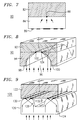
- FIG. 5 illustrates an alternative embodiment 60 where the re-direction of the optical radiation is provided by refraction.
- a first member 62 is to be attached to a second member 64 at location 66.
- second member 64 must be sufficiently transparent to the wavelength of the impinging radiation.
- second member 64 comprises a lensed surface 68 which functions to concentrate the collimated beam of radiation toward weld site 66.
- lens 68 may be formed during a molding operation.
- lens 68 may be etched.
- the shape of surface 68 is not critical, as long as a sufficient amount of radiation is concentrated relatively near to the desired weld site 66.
- arrangement 70 includes a first member 72 and a second member 74, where second member 74 is sufficiently transparent to the wavelength of the impinging radiation.
- Second member 74 includes a concentrating region 76, shaped as illustrated in FIG. 6, to direct the radiation toward weld site 78.
- concentrating region 76 is formed so as to provide for reflection of the radiation, since an air gap is illustrated as surrounding region 76.
- FIG. 7 illustrates yet another embodiment of the present invention which may be utilized with a transparent concentrating member.
- arrangement 80 includes a first member 82 and a second member 84, where second member 84 is sufficiently transparent to the wavelength of the impinging radiation.
- Second member 84 includes a diffraction grating 86 formed on the surface thereof.
- the diffraction grating may comprise a zone plate.
- a diffraction grating may be formed so as to result in concentrating the impinging radiation at a desired location, in this case at predetermined weld site 88.
- a concentrating aperture may be formed to include a parabolic-type opening such that a pair of laser welds are simultaneously formed within a single aperture.
- FIG. 8 illustrates, in a three-dimensional view, an exemplary arrangement 90 wherein a first piece part 92 is to be joined to a second piece part 94.
- Second piece part 94 includes an aperture 96 with a pair of parabolic-shaped walls in opening 98 and 100, as shown. Therefore, an incoming collimated beam will be directed to the location of parabolic aperture 96, the focal lines being along 102 and 104 in this embodiment. Therefore, a pair of linear laser welds will be formed within a single aperture.
- FIG. 9 illustrates an alternative embodiment 120 for providing linear laser welds.
- a first piece part 122 is to be laser welded to a second piece part 124, where piece part 124 is sufficiently transparent to the wavelength of the optical radiation used to perform the welding operation.
- Sidewalls 126 of piece part 124 are formed, as shown, to comprise parabolic shapes so as to focus the incoming collimated radiation along lines 130 and 132.
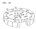
- FIG. 10 illustrates an exemplary piece part 140 including a plurality of various apertures which may be utilized as discussed above.
- the apertures of piece part 140 are shown as terminating in geometries other than a point or straight line.
- a set of four apertures 142 are illustrated as terminating in arcs, which may provide for bonding around the periphery of a circular piece part, for example.
- the apertures are formed to include sidewalls which provide for concentration of the laser radiation along the apex.
- Aperture 144 is illustrated as terminating in a cross-shaped apex, another suitable form. In general, any desired geometry may be used to provide the desired results.
- concentrating features may be utilized with various types of laser-based bonding procedures, including, but not limited to, welding, soldering or tacking
Landscapes
- Physics & Mathematics (AREA)
- Optics & Photonics (AREA)
- Engineering & Computer Science (AREA)
- Mechanical Engineering (AREA)
- Plasma & Fusion (AREA)
- Health & Medical Sciences (AREA)
- Electromagnetism (AREA)
- Toxicology (AREA)
- Lining Or Joining Of Plastics Or The Like (AREA)
- Laser Beam Processing (AREA)
- Adhesives Or Adhesive Processes (AREA)
Abstract
Description
- The present invention relates to arrangements for laser bonding.
- Laser bonding has been successfully utilized in a number of applications to provide joining of piece parts. See, for example, U. S. patent 4,990,741 entitled "Method of Laser Welding" and issued to R.J. Moores et al. on February 5, 1991. As disclosed, first and second metallic components may be joined along a weld path, with the beam focused by a low turbulent flow of an inert shielding gas along a portion of the path. In most applications, the material used to form the piece part (plastic or metal, for example) is opaque to the optical radiation and the radiation must therefore impinge the material from the side of the point of contact. This limitation is considered to further complicate and increase the cost of laser welding systems.
- Thus, a need remains in the art for increasing the utility of laser sources in various bonding applications.
- The need remaining in the prior art is addressed by the present invention which relates to laser bonding and, more particularly, to a scheme for improving the efficiency of laser bonding.
- In accordance with one embodiment of the present invention, at least one piece part is formed to include predefined features which concentrate the optical radiation toward predetermined locations which are to be joined.
- An advantage of the concentrating features is that the piece part itself may be formed of a material which is opaque to the wavelength of optical radiation.
- In one embodiment of the invention, a first piece part may be formed to include at least one aperture of a geometry (e.g., conical) which will provide concentration of the laser radiation at a predetermined location.
- In an alternative embodiment, a first piece part may be formed of a transparent material and include concentrating means, for example, an integral lens, to concentrate the radiation at the predetermined location.
- For an embodiment where both piece parts are transparent, an absorbing material (such as an epoxy) may be used at the interface between piece parts to absorb the radiation and become heated.
- Alternatively, a first piece part may be formed to including diffraction means for concentrating the radiation near the location where the piece parts are to be joined.
- An exemplary embodiment of the present invention may utilize conical apertures, with the apex of the cone located at or near the joining location.
- In an alternative embodiment, the apertures may comprise a parabolic shape, thus providing heating at a number of focii, creating a plurality of joints.
- Other and further embodiments and advantages of the present invention will become apparent during the course of the following discussion and by reference to the accompanying drawings.
- Referring now to the drawings, where like reference numerals represent like parts in several views:
- FIG. 1 illustrates an exemplary arrangement utilizing concentrated laser bonding in accordance with the present invention;
- FIG. 2 illustrates an alternative arrangement utilizing concentrated laser bonding;
- FIGs. 3 and 4 illustrate alternative aperture geometries which may be utilized in accordance with the teachings of the present invention:
- FIGs. 5-7 illustrate alternative embodiments of the present invention utilizing at least one transparent piece part and alternative concentrating means;
- FIGs. 8 and 9 illustrate embodiments of the present invention utilizing aperture geometries capable of forming a plurality of laser bonds within each aperture; and
- FIG. 10 illustrates an exemplary piece part including a number of differing aperture geometries suitable for use in providing bonding in accordance with the teaching of the present invention.
- FIG. 1 illustrates an
exemplary arrangement 10 for providing concentrated laser joining (which may be referred to hereinafter as "laser welding", but may also include laser tacking or bonding). -
Arrangement 10 includes afirst piece part 12 and a second piece part 14, where both piece parts may comprise a material which is opaque to optical radiation, for example, plastic or stainless steel. It is to be assumed that the piece parts are to be attached at locations A and B as shown in FIG. 1. - Piece part 14 is formed to include a pair of concentrating apertures 16 and 18. Concentrated optical radiation impinges upon piece part 14, as shown, entering apertures 16 and 18. In particular, the radiation is in the form of a plurality of collimated beams which enter apertures 16 and 18 (the geometry, number and location of the apertures being arbitrary and will be discussed in greater detail below; attachment will occur at any predetermined number of sites).
- The radiation entering apertures 16 and 18 is illustrated as being continuously concentrated toward
terminations terminations terminations end surface 24 of piece part 14. As along asterminations surface 24, sufficient heating will occur such that laser welding at locations A and B is achieved. - An
alternative arrangement 30 which may utilize laser welding is illustrated in FIG. 2. Afirst member 32 is joined to asecond member 34 atlocation 36, as shown. Here,aperture 38 is formed at the sidewall ofsecond member 34, wheresidewall 39 ofaperture 38 is angled so as to direct radiation upward.First member 32 may also have an angled sidewall (not shown). - Various other aperture geometries, including those illustrated in FIGs. 3 and 4, are possible. FIG. 3 illustrates a
piece part 40 including aconcentrating aperture 42 for providing laser welding . - As shown,
aperture 42 includes inwardly curvingsidewalls weld site 48. In this particular embodiment,aperture 42 terminates withinpiece part 40 at a location separated fromweld site 48. However, as mentioned above, the concentrating of the laser radiation at the terminations has been found to provide sufficient heating (as indicated by the dotted lines) to form a weld atsite 48. Thus, the process used to actually form apertures need not be precisely controlled, and the formation of apertures at least near the depth of the weld site will usually be sufficient. FIG. 4 illustrates another piece part including an aperture terminating at a position displaced from the weld site. In particular,piece part 50 includes aconcentrating aperture 52, in this case withconcave curving sidewalls site 58 is also illustrated in FIG. 4 as being separated from the location of the termination ofaperture 52. It is to be understood that various other apertures may be successfully used, to provide concentrated laser welding. In general, virtually any geometry capable of directing energy toward desired locations may be used. - FIG. 5 illustrates an
alternative embodiment 60 where the re-direction of the optical radiation is provided by refraction. In particular, afirst member 62 is to be attached to asecond member 64 atlocation 66. In this case,second member 64 must be sufficiently transparent to the wavelength of the impinging radiation. As shown,second member 64 comprises a lensedsurface 68 which functions to concentrate the collimated beam of radiation towardweld site 66. Ifsecond member 64 comprises a plastic material,lens 68 may be formed during a molding operation. Alternatively, ifsecond member 64 comprises a silicon substrate,lens 68 may be etched. In any case, the shape ofsurface 68 is not critical, as long as a sufficient amount of radiation is concentrated relatively near to the desiredweld site 66. - Another embodiment which also utilizes a transparent concentrating member is illustrated in FIG. 6. As shown,
arrangement 70 includes afirst member 72 and asecond member 74, wheresecond member 74 is sufficiently transparent to the wavelength of the impinging radiation.Second member 74 includes aconcentrating region 76, shaped as illustrated in FIG. 6, to direct the radiation towardweld site 78. In particular, concentratingregion 76 is formed so as to provide for reflection of the radiation, since an air gap is illustrated as surroundingregion 76. - FIG. 7 illustrates yet another embodiment of the present invention which may be utilized with a transparent concentrating member. In particular,
arrangement 80 includes afirst member 82 and asecond member 84, wheresecond member 84 is sufficiently transparent to the wavelength of the impinging radiation.Second member 84 includes adiffraction grating 86 formed on the surface thereof. In one embodiment, the diffraction grating may comprise a zone plate. As is well-known in the art, a diffraction grating may be formed so as to result in concentrating the impinging radiation at a desired location, in this case atpredetermined weld site 88. - As mentioned above, a concentrating aperture may be formed to include a parabolic-type opening such that a pair of laser welds are simultaneously formed within a single aperture. FIG. 8 illustrates, in a three-dimensional view, an
exemplary arrangement 90 wherein afirst piece part 92 is to be joined to asecond piece part 94.Second piece part 94 includes anaperture 96 with a pair of parabolic-shaped walls in opening 98 and 100, as shown. Therefore, an incoming collimated beam will be directed to the location ofparabolic aperture 96, the focal lines being along 102 and 104 in this embodiment. Therefore, a pair of linear laser welds will be formed within a single aperture. - FIG. 9 illustrates an
alternative embodiment 120 for providing linear laser welds. In this arrangement, afirst piece part 122 is to be laser welded to asecond piece part 124, wherepiece part 124 is sufficiently transparent to the wavelength of the optical radiation used to perform the welding operation.Sidewalls 126 ofpiece part 124 are formed, as shown, to comprise parabolic shapes so as to focus the incoming collimated radiation alonglines - As mentioned above, various aperture geometries are suitable for providing laser bonding, as long as the aperture provides sufficient concentration of the radiation near the bond location. FIG. 10 illustrates an
exemplary piece part 140 including a plurality of various apertures which may be utilized as discussed above. In contrast the embodiments discussed above, the apertures ofpiece part 140 are shown as terminating in geometries other than a point or straight line. In particular, a set of fourapertures 142 are illustrated as terminating in arcs, which may provide for bonding around the periphery of a circular piece part, for example. As with the arrangements discussed above, the apertures are formed to include sidewalls which provide for concentration of the laser radiation along the apex.Aperture 144 is illustrated as terminating in a cross-shaped apex, another suitable form. In general, any desired geometry may be used to provide the desired results. - It is to be understood that there exist may other arrangements suitable for providing concentrated laser attachment in accordance with the present invention. The various embodiments as discussed above are exemplary only, and for the purposes of explanation not limitation. Further, as mentioned above, the concentrating features may be utilized with various types of laser-based bonding procedures, including, but not limited to, welding, soldering or tacking
Claims (10)
- A laser bonding arrangement including a first piece part (12) and a second piece part (14) wherein the first piece part is to be laser bonded to the second piece part in at least one predetermined attachment site, characterised in that at least one piece part includes means (16) for concentrating radiation from the laser toward said at least one predetermined attachment site.
- An arrangement as defined in claim 1, wherein the concentrating means either comprises an aperture including inwardly tapering sidewalls and an apex for concentrating the laser radiation toward the at least one predetermined attachment site, or comprises a feature formed on the surface of at least one transparent piece part at a location capable of providing concentration of the laser radiation at the at least one attachment site, or comprises a region within the transparent piece part which is tapered so as to provide internal reflection sufficient to concentrate the laser radiation toward the at least one attachment site, or comprises a diffraction grating formed on the surface of the at least one transparent piece part.
- An arrangement as defined in claim 2 wherein the apex of the aperture is coincident with the attachment site, or remains separated from the attachment site.
- An arrangement as defined in claim 2 wherein the inwardly tapering sidewalls comprise parabolic shapes so as to provide for the formation of a plurality of laser attachments near the apex of the aperture.
- An arrangement as defined in claim 1 wherein at least one piece part is sufficiently transparent to the wavelength of the laser radiation utilized to provide attachment.
- An arrangement as defined in claim 2, wherein the feature comprises a lens.
- An arrangement as defined in claim 2, wherein the diffraction grating comprises a zone plate.
- An arrangement as defined in claim 1 wherein at least one predetermined attachment site comprises either essentially a point, or a line segment, or comprises an arc, or comprises a predefined geometry.
- A laser bonding process comprising the steps of:a) providing a first piece part and a second piece part, at least one piece part including means for concentrating laser radiation toward at least one predetermined attachment site used to join said first piece part to said second piece part;b) radiating said first and second piece parts with a laser such that the radiation impinges said concentrating means and is directed to the at least one attachment site; andc) maintaining the radiation of step b) for a time period sufficient to provide bonding of said first and second piece parts.
- The process of claim 9 wherein in performing step a), the concentrating means is formed to comprise an aperture including inwardly tapering sidewalls and an apex for concentrating the laser radiation toward the at least one predetermined attachment site.
Priority Applications (1)
| Application Number | Priority Date | Filing Date | Title |
|---|---|---|---|
| EP97100835A EP0771607A3 (en) | 1992-10-01 | 1993-09-22 | An arrangement for laser bonding |
Applications Claiming Priority (2)
| Application Number | Priority Date | Filing Date | Title |
|---|---|---|---|
| US07/955,168 US5276303A (en) | 1992-10-01 | 1992-10-01 | Laser bonding scheme |
| US955168 | 1992-10-01 |
Related Child Applications (2)
| Application Number | Title | Priority Date | Filing Date |
|---|---|---|---|
| EP97100835A Division EP0771607A3 (en) | 1992-10-01 | 1993-09-22 | An arrangement for laser bonding |
| EP97100835.4 Division-Into | 1997-01-21 |
Publications (2)
| Publication Number | Publication Date |
|---|---|
| EP0590873A1 true EP0590873A1 (en) | 1994-04-06 |
| EP0590873B1 EP0590873B1 (en) | 1997-11-26 |
Family
ID=25496469
Family Applications (2)
| Application Number | Title | Priority Date | Filing Date |
|---|---|---|---|
| EP93307507A Expired - Lifetime EP0590873B1 (en) | 1992-10-01 | 1993-09-22 | An arrangement for laser bonding |
| EP97100835A Withdrawn EP0771607A3 (en) | 1992-10-01 | 1993-09-22 | An arrangement for laser bonding |
Family Applications After (1)
| Application Number | Title | Priority Date | Filing Date |
|---|---|---|---|
| EP97100835A Withdrawn EP0771607A3 (en) | 1992-10-01 | 1993-09-22 | An arrangement for laser bonding |
Country Status (4)
| Country | Link |
|---|---|
| US (1) | US5276303A (en) |
| EP (2) | EP0590873B1 (en) |
| JP (1) | JPH06218567A (en) |
| DE (1) | DE69315409T2 (en) |
Cited By (2)
| Publication number | Priority date | Publication date | Assignee | Title |
|---|---|---|---|---|
| EP0719643A2 (en) * | 1994-12-28 | 1996-07-03 | Canon Kabushiki Kaisha | A liquid jet head manufacturing method and a liquid jet head manufactured by said manufacturing method |
| WO2005027530A2 (en) * | 2003-09-18 | 2005-03-24 | Koninklijke Philips Electronics N.V. | Method to position a frame |
Families Citing this family (12)
| Publication number | Priority date | Publication date | Assignee | Title |
|---|---|---|---|---|
| WO1998026440A1 (en) * | 1996-12-12 | 1998-06-18 | Candescent Technologies Corporation | Gap jumping to seal structure |
| JP3847517B2 (en) * | 2000-03-30 | 2006-11-22 | スタンレー電気株式会社 | Method of welding plastic parts by light energy |
| WO2002086558A2 (en) * | 2001-04-23 | 2002-10-31 | Willden Dee E | Wedge-shaped lensless laser focusing device |
| JP4042439B2 (en) * | 2002-03-18 | 2008-02-06 | トヨタ自動車株式会社 | Laser welded assembly |
| US6974207B2 (en) * | 2002-11-19 | 2005-12-13 | Lexmark International, Inc. | Laser welding methods and structures and control therefor including welded inkjet printheads |
| US20050099449A1 (en) * | 2003-11-07 | 2005-05-12 | Tim Frasure | Methods and structures for disassembling inkjet printhead components and control therefor |
| JP4506203B2 (en) * | 2004-02-27 | 2010-07-21 | 株式会社デンソー | Joint structure of resin member, laser welding method, and resin casing of electric equipment |
| EP2121285B1 (en) * | 2006-12-08 | 2013-07-10 | MAHLE International GmbH | Laser welding method |
| FR2934187B1 (en) * | 2008-07-24 | 2011-04-08 | Legris Sa | METHOD FOR MANUFACTURING A DEVICE BY LASER WELDING, DEVICE, ELEMENT OF THIS DEVICE AND CONNECTION FOR IMPLEMENTING SAID METHOD |
| JP2012215528A (en) * | 2011-04-01 | 2012-11-08 | Panasonic Industrial Devices Sunx Co Ltd | Detection sensor and method for manufacturing the same |
| ITUB20150956A1 (en) * | 2015-06-01 | 2016-12-01 | Automotive Lighting Italia S P A A Socio Unico | Method of manufacturing an automotive light and related automotive light |
| US20190061272A1 (en) * | 2017-08-28 | 2019-02-28 | GM Global Technology Operations LLC | Method for laser welding of non-transmissive composite materials |
Citations (10)
| Publication number | Priority date | Publication date | Assignee | Title |
|---|---|---|---|---|
| DE2343235A1 (en) * | 1973-08-28 | 1975-03-27 | Philips Patentverwaltung | Printed cct boards - enables mounting and connecting of subminiature components with soldering surfaces on one side |
| US4320281A (en) * | 1980-07-31 | 1982-03-16 | Western Electric Company, Inc. | Laser bonding technique and article formed thereby |
| JPS57160590A (en) * | 1981-03-31 | 1982-10-02 | Matsushita Electric Works Ltd | Welding method for contact point |
| JPS5897489A (en) * | 1981-12-04 | 1983-06-09 | Hitachi Ltd | Laser welding method |
| JPS6087987A (en) * | 1983-10-19 | 1985-05-17 | Toshiba Corp | Caulking method by laser light |
| EP0157439A1 (en) * | 1984-03-23 | 1985-10-09 | D.Drukker & Zn. N.V. | Method for attaching a diamond component to metal |
| GB2210309A (en) * | 1987-09-30 | 1989-06-07 | Toyo Seikan Kaisha Ltd | Butt welding method by means of laser beam |
| US4959522A (en) * | 1990-01-12 | 1990-09-25 | Chrysler Corporation | Transparent pressure foot |
| DE3939866A1 (en) * | 1989-12-01 | 1991-06-06 | Baasel Carl Lasertech | Laser engraving device for workpiece cylindrical mantle surface - has annular focussing mirror with curved mirror surface |
| DE4104256A1 (en) * | 1991-02-13 | 1992-08-20 | Thyssen Laser Technik Gmbh | Deep drawn article esp. automobile body part mfr. - using sheet made by laser welding inner and outer sheet portions |
Family Cites Families (14)
| Publication number | Priority date | Publication date | Assignee | Title |
|---|---|---|---|---|
| US3304403A (en) * | 1963-10-14 | 1967-02-14 | Texas Instruments Inc | Laser welding of contacts |
| US4237363A (en) * | 1977-02-04 | 1980-12-02 | Lemelson Jerome H | Beam welding apparatus and method |
| CH645208A5 (en) * | 1978-10-31 | 1984-09-14 | Bbc Brown Boveri & Cie | PROCESS FOR MAKING ELECTRICAL CONTACTS ON SEMICONDUCTOR COMPONENTS. |
| JPS58119481A (en) * | 1982-01-08 | 1983-07-15 | Kawasaki Steel Corp | Laser beam melting welding method |
| US4644126A (en) * | 1984-12-14 | 1987-02-17 | Ford Motor Company | Method for producing parallel-sided melt zone with high energy beam |
| JPS61169184A (en) * | 1985-01-23 | 1986-07-30 | Toyota Motor Corp | Laser welding method of butt joint |
| GB8620057D0 (en) * | 1986-08-18 | 1986-10-01 | Philips Nv | Cathode ray tube display device |
| US4737612A (en) * | 1987-02-04 | 1988-04-12 | Westinghouse Electric Corp. | Method of welding |
| US4833295A (en) * | 1988-05-17 | 1989-05-23 | Ford Motor Company | Welding of parts separated by a gap using a laser welding beam |
| DE3902292A1 (en) * | 1989-01-26 | 1990-08-02 | Bueco Buedenbender & Co | METHOD AND ARRANGEMENT FOR ADDITIONALLY WELDING A FOLD OF A CONTAINER |
| US4992643A (en) * | 1989-08-25 | 1991-02-12 | United States Department Of Energy | Method and device for controlling plume during laser welding |
| US4990741A (en) * | 1990-02-06 | 1991-02-05 | Rockwell International Corporation | Method of laser welding |
| US5049720A (en) * | 1990-08-24 | 1991-09-17 | Fmc Corporation | Laser welding apparatus with sky window |
| JP2799783B2 (en) * | 1991-04-30 | 1998-09-21 | 東洋製罐株式会社 | Manufacturing method of welded can body |
-
1992
- 1992-10-01 US US07/955,168 patent/US5276303A/en not_active Expired - Lifetime
-
1993
- 1993-09-22 DE DE69315409T patent/DE69315409T2/en not_active Expired - Fee Related
- 1993-09-22 EP EP93307507A patent/EP0590873B1/en not_active Expired - Lifetime
- 1993-09-22 EP EP97100835A patent/EP0771607A3/en not_active Withdrawn
- 1993-10-01 JP JP5245829A patent/JPH06218567A/en active Pending
Patent Citations (10)
| Publication number | Priority date | Publication date | Assignee | Title |
|---|---|---|---|---|
| DE2343235A1 (en) * | 1973-08-28 | 1975-03-27 | Philips Patentverwaltung | Printed cct boards - enables mounting and connecting of subminiature components with soldering surfaces on one side |
| US4320281A (en) * | 1980-07-31 | 1982-03-16 | Western Electric Company, Inc. | Laser bonding technique and article formed thereby |
| JPS57160590A (en) * | 1981-03-31 | 1982-10-02 | Matsushita Electric Works Ltd | Welding method for contact point |
| JPS5897489A (en) * | 1981-12-04 | 1983-06-09 | Hitachi Ltd | Laser welding method |
| JPS6087987A (en) * | 1983-10-19 | 1985-05-17 | Toshiba Corp | Caulking method by laser light |
| EP0157439A1 (en) * | 1984-03-23 | 1985-10-09 | D.Drukker & Zn. N.V. | Method for attaching a diamond component to metal |
| GB2210309A (en) * | 1987-09-30 | 1989-06-07 | Toyo Seikan Kaisha Ltd | Butt welding method by means of laser beam |
| DE3939866A1 (en) * | 1989-12-01 | 1991-06-06 | Baasel Carl Lasertech | Laser engraving device for workpiece cylindrical mantle surface - has annular focussing mirror with curved mirror surface |
| US4959522A (en) * | 1990-01-12 | 1990-09-25 | Chrysler Corporation | Transparent pressure foot |
| DE4104256A1 (en) * | 1991-02-13 | 1992-08-20 | Thyssen Laser Technik Gmbh | Deep drawn article esp. automobile body part mfr. - using sheet made by laser welding inner and outer sheet portions |
Non-Patent Citations (4)
| Title |
|---|
| D. J. O'HARA: "HOLOGRAPHIC SELECTIVE HEATING SYSTEM", IBM TECHNICAL DISCLOSURE BULLETIN., vol. 11, no. 9, February 1969 (1969-02-01), NEW YORK US, pages 1168 - 1169 * |
| PATENT ABSTRACTS OF JAPAN vol. 7, no. 1 (M - 183)<1146> 6 January 1983 (1983-01-06) * |
| PATENT ABSTRACTS OF JAPAN vol. 7, no. 199 (M - 240)<1344> 3 September 1983 (1983-09-03) * |
| PATENT ABSTRACTS OF JAPAN vol. 9, no. 231 (M - 414)<1954> 18 September 1985 (1985-09-18) * |
Cited By (5)
| Publication number | Priority date | Publication date | Assignee | Title |
|---|---|---|---|---|
| EP0719643A2 (en) * | 1994-12-28 | 1996-07-03 | Canon Kabushiki Kaisha | A liquid jet head manufacturing method and a liquid jet head manufactured by said manufacturing method |
| EP0719643A3 (en) * | 1994-12-28 | 1997-05-14 | Canon Kk | A liquid jet head manufacturing method and a liquid jet head manufactured by said manufacturing method |
| US5808641A (en) * | 1994-12-28 | 1998-09-15 | Canon Kabushiki Kaisha | Liquid jet head manufacturing method and a liquid jet head manufactured by said manufacturing method |
| WO2005027530A2 (en) * | 2003-09-18 | 2005-03-24 | Koninklijke Philips Electronics N.V. | Method to position a frame |
| WO2005027530A3 (en) * | 2003-09-18 | 2005-04-28 | Koninkl Philips Electronics Nv | Method to position a frame |
Also Published As
| Publication number | Publication date |
|---|---|
| DE69315409D1 (en) | 1998-01-08 |
| EP0771607A2 (en) | 1997-05-07 |
| EP0590873B1 (en) | 1997-11-26 |
| JPH06218567A (en) | 1994-08-09 |
| US5276303A (en) | 1994-01-04 |
| DE69315409T2 (en) | 1998-03-19 |
| EP0771607A3 (en) | 1997-06-04 |
Similar Documents
| Publication | Publication Date | Title |
|---|---|---|
| US5276303A (en) | Laser bonding scheme | |
| JP3973792B2 (en) | Manufacturing method of vehicular lamp | |
| EP1071973B1 (en) | Methods for connecting optical fibers to integrated optical waveguides | |
| JP2001334578A (en) | Method for welding resin by laser | |
| US20050205534A1 (en) | Single and dual lensed optical waveguide for uniform welding | |
| CN107405711A (en) | Laser beam connection method and Laser Processing optical instrument | |
| WO1992011971A1 (en) | Method and device for laser welding of galvanized steel sheets | |
| US4959522A (en) | Transparent pressure foot | |
| US20050077276A1 (en) | Method and apparatus for simultaneously heating materials | |
| US20240042546A1 (en) | Laser processing machine | |
| JP3866732B2 (en) | Laser bonding method for resin structures | |
| JP2929447B2 (en) | Welding method | |
| JPS57106489A (en) | Laser joining method | |
| EP0552468A1 (en) | Motor vehicle fuel tank and processes for its construction | |
| EP0997222A1 (en) | Device for the laser processing of materials | |
| CN111687538B (en) | Method for manufacturing bonded body | |
| US5369242A (en) | Split beam laser welding apparatus | |
| US5170029A (en) | Energy-beam welding method | |
| EP0997222A2 (en) | Device for the laser processing of materials | |
| JP3868116B2 (en) | Laser processing head | |
| JPH0123236B2 (en) | ||
| JPH09225663A (en) | Laser welding method | |
| JPS60213387A (en) | Method and device for welding plate materials | |
| JPH04220164A (en) | Joining method by energy beam | |
| CN115138968A (en) | Laser welding method and component |
Legal Events
| Date | Code | Title | Description |
|---|---|---|---|
| PUAI | Public reference made under article 153(3) epc to a published international application that has entered the european phase |
Free format text: ORIGINAL CODE: 0009012 |
|
| AK | Designated contracting states |
Kind code of ref document: A1 Designated state(s): DE FR GB |
|
| RAP3 | Party data changed (applicant data changed or rights of an application transferred) |
Owner name: AT&T CORP. |
|
| 17P | Request for examination filed |
Effective date: 19940921 |
|
| 17Q | First examination report despatched |
Effective date: 19951109 |
|
| GRAG | Despatch of communication of intention to grant |
Free format text: ORIGINAL CODE: EPIDOS AGRA |
|
| GRAH | Despatch of communication of intention to grant a patent |
Free format text: ORIGINAL CODE: EPIDOS IGRA |
|
| GRAH | Despatch of communication of intention to grant a patent |
Free format text: ORIGINAL CODE: EPIDOS IGRA |
|
| GRAA | (expected) grant |
Free format text: ORIGINAL CODE: 0009210 |
|
| AK | Designated contracting states |
Kind code of ref document: B1 Designated state(s): DE FR GB |
|
| XX | Miscellaneous (additional remarks) |
Free format text: TEILANMELDUNG 97100835.4 EINGEREICHT AM 21/01/97. |
|
| REF | Corresponds to: |
Ref document number: 69315409 Country of ref document: DE Date of ref document: 19980108 |
|
| ET | Fr: translation filed | ||
| PLBE | No opposition filed within time limit |
Free format text: ORIGINAL CODE: 0009261 |
|
| STAA | Information on the status of an ep patent application or granted ep patent |
Free format text: STATUS: NO OPPOSITION FILED WITHIN TIME LIMIT |
|
| 26N | No opposition filed | ||
| PGFP | Annual fee paid to national office [announced via postgrant information from national office to epo] |
Ref country code: FR Payment date: 20010823 Year of fee payment: 9 |
|
| PGFP | Annual fee paid to national office [announced via postgrant information from national office to epo] |
Ref country code: GB Payment date: 20010828 Year of fee payment: 9 |
|
| PGFP | Annual fee paid to national office [announced via postgrant information from national office to epo] |
Ref country code: DE Payment date: 20010928 Year of fee payment: 9 |
|
| REG | Reference to a national code |
Ref country code: GB Ref legal event code: IF02 |
|
| PG25 | Lapsed in a contracting state [announced via postgrant information from national office to epo] |
Ref country code: GB Free format text: LAPSE BECAUSE OF NON-PAYMENT OF DUE FEES Effective date: 20020922 |
|
| PG25 | Lapsed in a contracting state [announced via postgrant information from national office to epo] |
Ref country code: DE Free format text: LAPSE BECAUSE OF NON-PAYMENT OF DUE FEES Effective date: 20030401 |
|
| GBPC | Gb: european patent ceased through non-payment of renewal fee |
Effective date: 20020922 |
|
| PG25 | Lapsed in a contracting state [announced via postgrant information from national office to epo] |
Ref country code: FR Free format text: LAPSE BECAUSE OF NON-PAYMENT OF DUE FEES Effective date: 20030603 |
|
| REG | Reference to a national code |
Ref country code: FR Ref legal event code: ST |