EP0592224B1 - Bidirectional communication system with dual resonant antenna circuit for RF tags - Google Patents
Bidirectional communication system with dual resonant antenna circuit for RF tags Download PDFInfo
- Publication number
- EP0592224B1 EP0592224B1 EP93307994A EP93307994A EP0592224B1 EP 0592224 B1 EP0592224 B1 EP 0592224B1 EP 93307994 A EP93307994 A EP 93307994A EP 93307994 A EP93307994 A EP 93307994A EP 0592224 B1 EP0592224 B1 EP 0592224B1
- Authority
- EP
- European Patent Office
- Prior art keywords
- frequency
- antenna
- tag
- circuit
- signal
- Prior art date
- Legal status (The legal status is an assumption and is not a legal conclusion. Google has not performed a legal analysis and makes no representation as to the accuracy of the status listed.)
- Expired - Lifetime
Links
Images
Classifications
-
- G—PHYSICS
- G01—MEASURING; TESTING
- G01S—RADIO DIRECTION-FINDING; RADIO NAVIGATION; DETERMINING DISTANCE OR VELOCITY BY USE OF RADIO WAVES; LOCATING OR PRESENCE-DETECTING BY USE OF THE REFLECTION OR RERADIATION OF RADIO WAVES; ANALOGOUS ARRANGEMENTS USING OTHER WAVES
- G01S13/00—Systems using the reflection or reradiation of radio waves, e.g. radar systems; Analogous systems using reflection or reradiation of waves whose nature or wavelength is irrelevant or unspecified
- G01S13/74—Systems using reradiation of radio waves, e.g. secondary radar systems; Analogous systems
- G01S13/75—Systems using reradiation of radio waves, e.g. secondary radar systems; Analogous systems using transponders powered from received waves, e.g. using passive transponders, or using passive reflectors
- G01S13/751—Systems using reradiation of radio waves, e.g. secondary radar systems; Analogous systems using transponders powered from received waves, e.g. using passive transponders, or using passive reflectors wherein the responder or reflector radiates a coded signal
- G01S13/753—Systems using reradiation of radio waves, e.g. secondary radar systems; Analogous systems using transponders powered from received waves, e.g. using passive transponders, or using passive reflectors wherein the responder or reflector radiates a coded signal using frequency selective elements, e.g. resonator
-
- G—PHYSICS
- G01—MEASURING; TESTING
- G01S—RADIO DIRECTION-FINDING; RADIO NAVIGATION; DETERMINING DISTANCE OR VELOCITY BY USE OF RADIO WAVES; LOCATING OR PRESENCE-DETECTING BY USE OF THE REFLECTION OR RERADIATION OF RADIO WAVES; ANALOGOUS ARRANGEMENTS USING OTHER WAVES
- G01S13/00—Systems using the reflection or reradiation of radio waves, e.g. radar systems; Analogous systems using reflection or reradiation of waves whose nature or wavelength is irrelevant or unspecified
- G01S13/74—Systems using reradiation of radio waves, e.g. secondary radar systems; Analogous systems
- G01S13/75—Systems using reradiation of radio waves, e.g. secondary radar systems; Analogous systems using transponders powered from received waves, e.g. using passive transponders, or using passive reflectors
- G01S13/751—Systems using reradiation of radio waves, e.g. secondary radar systems; Analogous systems using transponders powered from received waves, e.g. using passive transponders, or using passive reflectors wherein the responder or reflector radiates a coded signal
- G01S13/758—Systems using reradiation of radio waves, e.g. secondary radar systems; Analogous systems using transponders powered from received waves, e.g. using passive transponders, or using passive reflectors wherein the responder or reflector radiates a coded signal using a signal generator powered by the interrogation signal
-
- G—PHYSICS
- G06—COMPUTING; CALCULATING OR COUNTING
- G06K—GRAPHICAL DATA READING; PRESENTATION OF DATA; RECORD CARRIERS; HANDLING RECORD CARRIERS
- G06K19/00—Record carriers for use with machines and with at least a part designed to carry digital markings
- G06K19/06—Record carriers for use with machines and with at least a part designed to carry digital markings characterised by the kind of the digital marking, e.g. shape, nature, code
- G06K19/067—Record carriers with conductive marks, printed circuits or semiconductor circuit elements, e.g. credit or identity cards also with resonating or responding marks without active components
- G06K19/07—Record carriers with conductive marks, printed circuits or semiconductor circuit elements, e.g. credit or identity cards also with resonating or responding marks without active components with integrated circuit chips
- G06K19/0723—Record carriers with conductive marks, printed circuits or semiconductor circuit elements, e.g. credit or identity cards also with resonating or responding marks without active components with integrated circuit chips the record carrier comprising an arrangement for non-contact communication, e.g. wireless communication circuits on transponder cards, non-contact smart cards or RFIDs
Definitions
- This invention relates to the field of two-way communication devices in which one such device is passive and, more particularly, to two-way communication devices in which one device is a stationary device and the other device is a portable passive device.
- RF tag uses radio frequency energy to remotely identify itself to a reader, which may be several inches to many feet away.
- the tag may be mounted on a container for cargo management or carried by a person for security access. It is preferable that the tag not only be extremely inexpensive but also rugged and reliable.
- FIG. 1 shows a typical RF tag system known in the prior art.
- a reader 10 and tag 12 engage in two-way communication.
- Power 14 is imported into reader 10 and transmitted as RF energy signal 16 to tag 12.
- tag 12 After processing by tag 12, tag 12 transmits RF modulated signal 18 which is received by reader 10. Utilizing this RF modulated signal 18, reader 10 obtains tag ID code 20 which allows it to identify tag 12.
- tags having a frequency less than one MHz are preferred.
- Such tags provide the advantage of permitting through-the-body operation and easy clock generation.
- For short read ranges on the order of three feet or less, such a tag operates without a battery, using only the energy absorbed from the reader's RF field. The energy is coupled from the reader to the tag magnetostatically. This coupling is a near-field phenomenon which is analogous to an air core transformer having a very low coupling coefficient.
- the signal level returning from the tag to the reader is much lower than the transmitted signal from the reader. It has been found that in the three foot read range, the returning signal from tag to reader is more than 80 dB less than the transmitted signal from the reader to the tag.
- This large signal differential requires a large dynamic range in the reader receiver or a frequency conversion in the tag so that the received frequency at the tag is different from the transmitted frequency.
- Frequency conversion enables front-end filtering in the receiver of the transmitted frequency. At the low frequencies desired for RF tag operation, frequency conversion is a simple function performed by digital circuitry. Accordingly, a dual frequency RF tag system is desirable.
- the power received at the tag may be extremely low. It is not infrequent for such power to be less than 100 ⁇ W. However, this is enough power to operate a digital CMOS integrated circuit as long as a relatively large voltage in the range of greater than 3 volts is generated. In order to conserve power in the tag, the voltage needed to transmit the signal from the tag should be minimized. Consequently, there is a need for an antenna circuit capable of deriving large voltages from the reader signal but conserving power in the transmission of the return signal.
- a stationary member transmits a signal at a first frequency (25kHz) via a magnetic field and data stored in a portable passive member (tag) is transmitted back at a second frequency (200kHz) via a magnetic field.
- a parallel resonant circuit is composed of a coil serving as a receive antenna plus a capacitor, whilst a separate series resonant circuit is composed of a capacitor and a coil serving as a transmit antenna.
- the parallel resonant circuit feeds a full-wave rectifier bridge whose output connects to a positive D.C. supply terminal.
- the present invention provides a two-way communication system as defined in Claim 1 hereinafter.
- a two-way communication system may be provided having a stationary member and a portable passive member having circuitry for storing and transmitting coded information.
- the stationary member transmits a signal at a first frequency by means of a magnetic field.
- the portable passive member transmits coded information stored on its circuitry at a second frequency also via a magnetic field.
- An antenna circuit is provided in the portable passive member which is parallel resonant at the receive frequency and series resonant at the transmit frequency.
- the parallel resonant circuit of the antenna circuit derives operating power from the signal transmitted by the stationary member.
- the parallel resonant circuit presents a high impedance resulting in a large voltage with small current flow.
- the series resonant circuit transmits the coded information at a second frequency which differs from the first frequency.
- the series resonant circuit presents a low impedance which results in a large current with a small applied voltage.
- the series resonance minimizes the effect of the transmitted signal on the receive signal, enabling simultaneous transmit and receive operations from the portable passive member through the same antenna circuit.
- the magnetic field generated by coil antenna 26 is received by inductor antenna 30.
- the circuitry in tag 28 derives power from this received signal and generates a received voltage represented by Vr. This received voltage is used to operate tag transmitter 32 which produces a signal at a second frequency. This signal is transmitted by tag 28 by means of an inductor antenna 30.
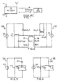
- FIGs 3 and 4 show two possible configurations of the dual frequency antenna circuit.
- tag 34 is shown having transmit and receive antenna 36 provided in parallel alignment with a first capacitor 38.
- Antenna 36 and capacitor 38 are designed to create a parallel resonance at the frequency of the receive signal.
- a second capacitor 40 is provided in serial alignment with the parallel combination of capacitor 38 and antenna 36.
- load impedance 42 is substantially greater than the impedance of capacitor 40 at the frequency of the received signal, little voltage is lost across capacitor 40.
- the received voltage is large enough to drive transmitter 44 which produces a signal containing the coded information at a lower frequency than the signal received by tag 34.
- the parallel resonant circuit created by antenna 36 and first capacitor 38 produces a high impedance which creates a large voltage and a small flow of current at the tag receive frequency.
- the series resonant circuit formed by the parallel combination of antenna 36 and capacitor 38 in serial alignment with capacitor 40 presents a low impedance, which results in a large current having a small applied voltage at the tag transmit frequency.
- the dual resonant antenna circuit of the present invention shown in Figure 4 transmits a signal of coded information at a higher frequency than the signal received.
- tag 46 is provided with antenna 48 which receives the signal generated by the reader.
- Capacitor 50 is provided in parallel alignment with antenna 48 to form the parallel circuit.
- the parallel combination of the capacitor 50 and antenna 48 are provided in serial alignment with transmit antenna 52 to form the serial circuit of the dual resonant circuit.
- the parallel resonant circuit formed by antenna 48 and capacitor 50 presents a high impedance which results in a large voltage with small current flow at the tag receive frequency.
- the series resonant circuit formed by the parallel combination of receive antenna 48 and capacitor 40 in serial alignment with antenna 52 presents a low impedance, resulting in a large current with a small applied voltage at the tag transmit frequency. This allows transmitter 56 to transmit a signal at a higher frequency than that received from the reader.
- the antenna circuit can be modified by placing the load impedance 42, 54 connected across only the parallel resonant circuits.
- Such a modified configuration eliminates the voltage drop occurring over the series element.
- the received signal will have a strong transmit component which must be filtered in order for such a configuration to operate properly.
- the present dual resonant antenna circuit provides both a cost reduction and a size reduction in the production of the tag. Because such tags are generally planar in shape, the use of a single antenna circuit permits the tag to be generally in the size of a credit card. The use of the dual circuit and single antenna prevents the problem of the receive antenna and transmit antenna talking to each other.
- the present dual resonant antenna circuit may also be used in any communication system having an active member and at least one passive member.
- the passive members derive their operating power from the magnetic field generated by the active member.
- the parallel resonant circuit provided in the passive members is resonant at the transmit frequency of the active member and derives operating power from the active member's magnetic field. This operating power is used to transmit a signal using the passive member's serial resonant circuit.
- the present dual resonant antenna circuit may further be used in a communication system having two active members.
- the parallel resonant circuit of each active member is resonant at the frequency of the other active member's transmit frequency.
- simultaneous transmit and receive operations may be conducted through a single antenna in each member.
- Such a communication system is ideally suited for use in walkie-talkie devices and in toys.
Description
- This invention relates to the field of two-way communication devices in which one such device is passive and, more particularly, to two-way communication devices in which one device is a stationary device and the other device is a portable passive device.
- It is well known to use two-way communication devices utilizing a stationary member and a portable passive member. Such portable passive members are generally radio frequency (RF) tags. An RF tag uses radio frequency energy to remotely identify itself to a reader, which may be several inches to many feet away. The tag may be mounted on a container for cargo management or carried by a person for security access. It is preferable that the tag not only be extremely inexpensive but also rugged and reliable.
- Figure 1 shows a typical RF tag system known in the prior art. Therein, a
reader 10 andtag 12 engage in two-way communication.Power 14 is imported intoreader 10 and transmitted asRF energy signal 16 totag 12. After processing bytag 12,tag 12 transmits RF modulatedsignal 18 which is received byreader 10. Utilizing this RF modulatedsignal 18,reader 10 obtainstag ID code 20 which allows it to identifytag 12. - For security access applications, low frequency tags having a frequency less than one MHz are preferred. Such tags provide the advantage of permitting through-the-body operation and easy clock generation. For short read ranges on the order of three feet or less, such a tag operates without a battery, using only the energy absorbed from the reader's RF field. The energy is coupled from the reader to the tag magnetostatically. This coupling is a near-field phenomenon which is analogous to an air core transformer having a very low coupling coefficient.
- Since there is no external power supply in the circuit from the reader antenna to the tag and back to the reader, the signal level returning from the tag to the reader is much lower than the transmitted signal from the reader. It has been found that in the three foot read range, the returning signal from tag to reader is more than 80 dB less than the transmitted signal from the reader to the tag. This large signal differential requires a large dynamic range in the reader receiver or a frequency conversion in the tag so that the received frequency at the tag is different from the transmitted frequency. Frequency conversion enables front-end filtering in the receiver of the transmitted frequency. At the low frequencies desired for RF tag operation, frequency conversion is a simple function performed by digital circuitry. Accordingly, a dual frequency RF tag system is desirable.
- The power received at the tag may be extremely low. It is not infrequent for such power to be less than 100µW. However, this is enough power to operate a digital CMOS integrated circuit as long as a relatively large voltage in the range of greater than 3 volts is generated. In order to conserve power in the tag, the voltage needed to transmit the signal from the tag should be minimized. Consequently, there is a need for an antenna circuit capable of deriving large voltages from the reader signal but conserving power in the transmission of the return signal.
- In GB-A-2 076 259 a stationary member transmits a signal at a first frequency (25kHz) via a magnetic field and data stored in a portable passive member (tag) is transmitted back at a second frequency (200kHz) via a magnetic field. In the tag a parallel resonant circuit is composed of a coil serving as a receive antenna plus a capacitor, whilst a separate series resonant circuit is composed of a capacitor and a coil serving as a transmit antenna. The parallel resonant circuit feeds a full-wave rectifier bridge whose output connects to a positive D.C. supply terminal.
- The present invention provides a two-way communication system as defined in
Claim 1 hereinafter. - A two-way communication system may be provided having a stationary member and a portable passive member having circuitry for storing and transmitting coded information. The stationary member transmits a signal at a first frequency by means of a magnetic field. The portable passive member transmits coded information stored on its circuitry at a second frequency also via a magnetic field. An antenna circuit is provided in the portable passive member which is parallel resonant at the receive frequency and series resonant at the transmit frequency.
- The parallel resonant circuit of the antenna circuit derives operating power from the signal transmitted by the stationary member. The parallel resonant circuit presents a high impedance resulting in a large voltage with small current flow. The series resonant circuit transmits the coded information at a second frequency which differs from the first frequency. The series resonant circuit presents a low impedance which results in a large current with a small applied voltage. The series resonance minimizes the effect of the transmitted signal on the receive signal, enabling simultaneous transmit and receive operations from the portable passive member through the same antenna circuit.
- The preferred embodiments of the invention will now be described, by way of example, with reference to the accompanying drawings, in which:
- Figure 1 is a schematic representation of a prior art RF tag system;
- Figure 2 is a schematic representation of a two-way communication system showing the reader transmitter and the tag receive and transmit circuit;
- Figure 3 is a schematic representation of a dual frequency antenna circuit ; and
- Figure 4 is a schematic representation of a presently preferred embodiment of the dual frequency antenna circuit of the present invention.
- Figure 2 represents a typical reader transmit
circuit and tag receive and transmit circuit.
In Figure 2,
reader 22 transmits a signal at a first frequency.Reader transmitter 24 generates a current at a desired frequency.Coil antenna 26 generates a magnetic field at the desired frequency. -
- When
tag 28 approachesreader 22, the magnetic field generated bycoil antenna 26 is received byinductor antenna 30. The circuitry intag 28 derives power from this received signal and generates a received voltage represented by Vr. This received voltage is used to operatetag transmitter 32 which produces a signal at a second frequency. This signal is transmitted bytag 28 by means of aninductor antenna 30. - Figures 3 and 4 show two possible configurations of the dual frequency antenna circuit. In Figure 3,
tag 34 is shown having transmit and receiveantenna 36 provided in parallel alignment with afirst capacitor 38.Antenna 36 andcapacitor 38 are designed to create a parallel resonance at the frequency of the receive signal. Asecond capacitor 40 is provided in serial alignment with the parallel combination ofcapacitor 38 andantenna 36. As long asload impedance 42 is substantially greater than the impedance ofcapacitor 40 at the frequency of the received signal, little voltage is lost acrosscapacitor 40. The received voltage is large enough to drivetransmitter 44 which produces a signal containing the coded information at a lower frequency than the signal received bytag 34. - In the dual frequency antenna circuit of Figure 3, the parallel resonant circuit created by
antenna 36 andfirst capacitor 38 produces a high impedance which creates a large voltage and a small flow of current at the tag receive frequency. The series resonant circuit formed by the parallel combination ofantenna 36 andcapacitor 38 in serial alignment withcapacitor 40 presents a low impedance, which results in a large current having a small applied voltage at the tag transmit frequency. By utilization of the dual resonant antenna circuit of Figure 3,antenna 36 transmit a signal of coded information at a frequency less than the frequency of the signal which it receives. - In contrast to the dual resonant circuit of Figure 3, the dual resonant antenna circuit of the present invention shown in Figure 4 transmits a signal of coded information at a higher frequency than the signal received. In the dual antenna circuit of Figure 4,
tag 46 is provided withantenna 48 which receives the signal generated by the reader. Capacitor 50 is provided in parallel alignment withantenna 48 to form the parallel circuit. The parallel combination of the capacitor 50 andantenna 48 are provided in serial alignment with transmitantenna 52 to form the serial circuit of the dual resonant circuit. - In the configuration of Figure 4, all of the transmit current flows through
antenna 52. However, only some of the current passes throughantenna 48. Because most of the received voltage is developed acrossantenna 48,antennas antenna 52, little voltage will be lost acrossantenna 52. - The parallel resonant circuit formed by
antenna 48 and capacitor 50 presents a high impedance which results in a large voltage with small current flow at the tag receive frequency. The series resonant circuit formed by the parallel combination of receiveantenna 48 andcapacitor 40 in serial alignment withantenna 52 presents a low impedance, resulting in a large current with a small applied voltage at the tag transmit frequency. This allowstransmitter 56 to transmit a signal at a higher frequency than that received from the reader. - In the configuration of both Figures 3 and 4, the antenna circuit can be modified by placing the
load impedance 42, 54 connected across only the parallel resonant circuits. Such a modified configuration eliminates the voltage drop occurring over the series element. However, the received signal will have a strong transmit component which must be filtered in order for such a configuration to operate properly. - The present dual resonant antenna circuit provides both a cost reduction and a size reduction in the production of the tag. Because such tags are generally planar in shape, the use of a single antenna circuit permits the tag to be generally in the size of a credit card. The use of the dual circuit and single antenna prevents the problem of the receive antenna and transmit antenna talking to each other.
- A simulation was conducted of the dual resonant antenna circuit of Figure 2. That simulation showed that the transmitted current from
tag transmitter 32 has little effect on the received voltage, Vr. This is true even when the current in the antenna coil due to the transmitter is as large as the antenna coil current from the received signal. In the simulated antenna circuit,reader transmitter 24 creates a current of 50 mA and creates a frequency of 175 kHz. Thetag transmitter 32 creates a current of 500 µA and operates at a frequency of 87.5 kHz. The values of the remaining elements in the simulation are shown beside the respective element in Figure 2. In the simulation of the dual antenna circuit of Figure 2, the received voltage varied by less than 5% due to the transmitted current. Thus, the provision of the transmit and receive functions on the same circuit is practical. - The present dual resonant antenna circuit may also be used in any communication system having an active member and at least one passive member. In such a communication system, the passive members derive their operating power from the magnetic field generated by the active member. The parallel resonant circuit provided in the passive members is resonant at the transmit frequency of the active member and derives operating power from the active member's magnetic field. This operating power is used to transmit a signal using the passive member's serial resonant circuit.
- The present dual resonant antenna circuit may further be used in a communication system having two active members. In such a communication system, the parallel resonant circuit of each active member is resonant at the frequency of the other active member's transmit frequency. By utilization of the dual resonant circuit, simultaneous transmit and receive operations may be conducted through a single antenna in each member. Such a communication system is ideally suited for use in walkie-talkie devices and in toys.
- In the foregoing specification certain preferred practices and embodiments of this invention have been set out, however, it will be understood that the invention may be otherwise embodied within the scope of the following claims.
Claims (1)
- A two-way communication system having a stationary member (22) and a portable passive member (48), said portable passive member having circuitry for storing and transmitting coded information, said stationary member transmitting a signal at a first frequency via a magnetic field and said portable passive member transmitting coded information stored by the circuitry in said portable passive member at a second frequency via a magnetic field, the system having an antenna circuit (48, 50, 52) provided in said portable passive member, said antenna circuit comprising:(a) a parallel resonant circuit (48, 50) having a receive antenna (48) for deriving operating power from said signal at a first frequency for use in said circuitry provided in said portable passive member (46) said parallel resonant circuit comprising a capacitor (50) in parallel alignment with an inductor coil, said inductor coil serving as the receive antenna for said portable passive member; and(b) a series resonant circuit (48, 50, 52) having a transmit antenna (52) for transmitting at a second frequency said coded information stored by said circuitry in said portable passive member, said second frequency differing from said first frequency, said series resonant circuit comprises a second inductor coil (52) in serial alignment with the parallel combination of said first inductor coil (48) and said capacitor (50), said second inductor coil serving as a transmit antenna for said portable passive member.
Applications Claiming Priority (2)
| Application Number | Priority Date | Filing Date | Title |
|---|---|---|---|
| US07/957,119 US5317330A (en) | 1992-10-07 | 1992-10-07 | Dual resonant antenna circuit for RF tags |
| US957119 | 1992-10-07 |
Publications (2)
| Publication Number | Publication Date |
|---|---|
| EP0592224A1 EP0592224A1 (en) | 1994-04-13 |
| EP0592224B1 true EP0592224B1 (en) | 2002-08-14 |
Family
ID=25499098
Family Applications (1)
| Application Number | Title | Priority Date | Filing Date |
|---|---|---|---|
| EP93307994A Expired - Lifetime EP0592224B1 (en) | 1992-10-07 | 1993-10-07 | Bidirectional communication system with dual resonant antenna circuit for RF tags |
Country Status (4)
| Country | Link |
|---|---|
| US (1) | US5317330A (en) |
| EP (1) | EP0592224B1 (en) |
| JP (1) | JPH06204922A (en) |
| DE (1) | DE69332198T2 (en) |
Families Citing this family (33)
| Publication number | Priority date | Publication date | Assignee | Title |
|---|---|---|---|---|
| EP0650216B1 (en) * | 1993-10-26 | 2000-01-19 | Texas Instruments Deutschland Gmbh | Antenna circuit |
| EP0704928A3 (en) * | 1994-09-30 | 1998-08-05 | HID Corporation | RF transponder system with parallel resonant interrogation and series resonant response |
| US5798693A (en) * | 1995-06-07 | 1998-08-25 | Engellenner; Thomas J. | Electronic locating systems |
| US5640002A (en) * | 1995-08-15 | 1997-06-17 | Ruppert; Jonathan Paul | Portable RF ID tag and barcode reader |
| US7511621B1 (en) | 1995-08-31 | 2009-03-31 | Intermec Ip Corp. | High-performance mobile power antennas |
| FR2741978B1 (en) * | 1995-12-01 | 1998-01-23 | Pierre Raimbault | SUPPLY AND MODULATION CIRCUIT FOR A REMOTE INTERROGEABLE LABEL |
| US6104311A (en) * | 1996-08-26 | 2000-08-15 | Addison Technologies | Information storage and identification tag |
| US6147606A (en) * | 1998-03-26 | 2000-11-14 | Intermec Ip Corp. | Apparatus and method for radio frequency transponder with improved read distance |
| US6785447B2 (en) | 1998-10-09 | 2004-08-31 | Fujitsu Limited | Single and multilayer waveguides and fabrication process |
| DE59913632D1 (en) * | 1999-01-08 | 2006-08-10 | Anatoli Stobbe | Security system, transponder and receiving device |
| BR0110648A (en) * | 2000-05-08 | 2003-04-01 | Checkpoint Systems Inc | Radio Frequency Detection and Identification System |
| US6584301B1 (en) * | 2000-05-25 | 2003-06-24 | Motorola, Inc. | Inductive reader device and method with integrated antenna and signal coupler |
| DE60119437T2 (en) | 2000-06-19 | 2007-03-01 | Supersensor (Proprietary) Ltd. | Broad band high impedance transponder for electronic identification system |
| DE10042875C2 (en) * | 2000-08-31 | 2002-12-12 | Skidata Ag | communication terminal |
| US6753783B2 (en) * | 2001-03-30 | 2004-06-22 | Augmentech, Inc. | Patient positioning monitoring apparatus and method of use thereof |
| US7962361B2 (en) | 2002-11-07 | 2011-06-14 | Novitaz | Customer relationship management system for physical locations |
| US8600804B2 (en) | 2002-11-07 | 2013-12-03 | Novitaz, Inc. | Customer relationship management system for physical locations |
| EP1434160A3 (en) * | 2002-12-24 | 2004-09-15 | Matsushita Electric Industrial Co., Ltd. | Non-contact IC card reading/writing apparatus |
| DE10304479B3 (en) * | 2003-02-04 | 2004-07-22 | Siemens Audiologische Technik Gmbh | Data transmission and reception device for remote control of hearing aid with transmission and reception coils wound around common core |
| US7512383B2 (en) * | 2003-11-26 | 2009-03-31 | Starkey Laboratories, Inc. | Transmit-receive switching in wireless hearing aids |
| NL1025725C2 (en) * | 2004-03-15 | 2005-09-16 | Nedap Nv | Combined RFID and anti theft label for e.g. shop goods, contains main outer coil and auxiliary inner coil |
| ES2253104B1 (en) * | 2004-10-20 | 2007-07-16 | Alberto Murgui Faubell | SYSTEM FOR DETECTION OF RESONANT LABELS FOR ANTIHURT EQUIPMENT AND ASSOCIATED PROCEDURE. |
| US20070087838A1 (en) * | 2005-09-12 | 2007-04-19 | Jonathan Bradbury | Video game media |
| US7883420B2 (en) | 2005-09-12 | 2011-02-08 | Mattel, Inc. | Video game systems |
| US8467266B2 (en) * | 2006-06-13 | 2013-06-18 | Seispec, L.L.C. | Exploring a subsurface region that contains a target sector of interest |
| US7382684B2 (en) * | 2006-06-13 | 2008-06-03 | Seispec, L.L.C. | Method for selective bandlimited data acquisition in subsurface formations |
| US20090058614A1 (en) * | 2007-08-30 | 2009-03-05 | Em Microelectronic-Marin S.A. | Electronic identification device or transponder fitted with two antennae tuned to different frequencies |
| US8514141B2 (en) * | 2009-04-13 | 2013-08-20 | Visible Assets, Inc. | Low-frequency tag with separate transmit and receive antennas |
| WO2011159171A2 (en) | 2010-06-11 | 2011-12-22 | Trident Rfid Pty Ltd | A transponder, rfid system and methods of operation |
| US20120312879A1 (en) * | 2011-01-06 | 2012-12-13 | John Rolin | PCB Design and Card Assembly for an Active RFID Tag in Credit Card Form Factor |
| EP2535838A1 (en) * | 2011-06-16 | 2012-12-19 | Gemalto SA | Contactless communication method with negative modulation |
| US9179492B2 (en) * | 2011-10-26 | 2015-11-03 | Texas Instruments Deutschland Gmbh | Electronic device, method and system for half duplex data transmission |
| US20140358099A1 (en) * | 2013-05-30 | 2014-12-04 | Children's Healthcare Of Atlanta | RF Backscatter Sensor for Measuring Moisture and Other Biological Data |
Family Cites Families (18)
| Publication number | Priority date | Publication date | Assignee | Title |
|---|---|---|---|---|
| US3440633A (en) * | 1965-10-18 | 1969-04-22 | Jorgen P Vinding | Interrogator-responder identification system |
| US3618108A (en) * | 1969-12-31 | 1971-11-02 | Westinghouse Electric Corp | Compact electrically steerable tracking antenna feed system |
| GB2076259B (en) * | 1980-05-13 | 1984-03-28 | Rodrian James A | Animal identification and estrus detection system |
| GB2077555A (en) * | 1980-05-27 | 1981-12-16 | Standard Telephones Cables Ltd | Electronic tally apparatus |
| US4464663A (en) * | 1981-11-19 | 1984-08-07 | Ball Corporation | Dual polarized, high efficiency microstrip antenna |
| NL8200138A (en) * | 1982-01-14 | 1983-08-01 | Nedap Nv | DETECTION SYSTEM. |
| US4542532A (en) * | 1984-03-09 | 1985-09-17 | Medtronic, Inc. | Dual-antenna transceiver |
| GB8408538D0 (en) * | 1984-04-03 | 1984-05-16 | Senelco Ltd | Transmitter-responder systems |
| CA1260609A (en) * | 1986-09-12 | 1989-09-26 | Her Majesty The Queen, In Right Of Canada, As Represented By The Minister Of National Defence | Wide bandwidth multiband feed system with polarization diversity |
| DK110387A (en) * | 1987-03-03 | 1988-09-04 | Electronic Identification Syst | COMMUNICATION SYSTEM |
| GB8718552D0 (en) * | 1987-08-05 | 1987-09-09 | British Railways Board | Track to train communications systems |
| US4963880A (en) * | 1988-05-03 | 1990-10-16 | Identitech | Coplanar single-coil dual function transmit and receive antenna for proximate surveillance system |
| JP2612190B2 (en) * | 1988-08-31 | 1997-05-21 | 山武ハネウエル株式会社 | Full-duplex communication device consisting of answering device and interrogation device |
| US5084699A (en) * | 1989-05-26 | 1992-01-28 | Trovan Limited | Impedance matching coil assembly for an inductively coupled transponder |
| US5099227A (en) * | 1989-07-18 | 1992-03-24 | Indala Corporation | Proximity detecting apparatus |
| US5012224A (en) * | 1989-12-05 | 1991-04-30 | Sensormatic Electronics Corporation | Audible tag for magnetic electronic article surveillance systems |
| US5099226A (en) * | 1991-01-18 | 1992-03-24 | Interamerican Industrial Company | Intelligent security system |
| US5241298A (en) * | 1992-03-18 | 1993-08-31 | Security Tag Systems, Inc. | Electrically-and-magnetically-coupled, batteryless, portable, frequency divider |
-
1992
- 1992-10-07 US US07/957,119 patent/US5317330A/en not_active Expired - Lifetime
-
1993
- 1993-10-05 JP JP5274968A patent/JPH06204922A/en active Pending
- 1993-10-07 DE DE69332198T patent/DE69332198T2/en not_active Expired - Lifetime
- 1993-10-07 EP EP93307994A patent/EP0592224B1/en not_active Expired - Lifetime
Also Published As
| Publication number | Publication date |
|---|---|
| US5317330A (en) | 1994-05-31 |
| JPH06204922A (en) | 1994-07-22 |
| EP0592224A1 (en) | 1994-04-13 |
| DE69332198D1 (en) | 2002-09-19 |
| DE69332198T2 (en) | 2003-03-27 |
Similar Documents
| Publication | Publication Date | Title |
|---|---|---|
| EP0592224B1 (en) | Bidirectional communication system with dual resonant antenna circuit for RF tags | |
| US6944424B2 (en) | RFID tag having combined battery and passive power source | |
| US5426667A (en) | System for the contactless exchange of data, and responder for use in such a system | |
| US3689885A (en) | Inductively coupled passive responder and interrogator unit having multidimension electromagnetic field capabilities | |
| US4857893A (en) | Single chip transponder device | |
| CA2215257C (en) | Power transmission system, ic card and information communication system using ic card | |
| EP0274526B1 (en) | Transponder device | |
| US4818855A (en) | Identification system | |
| JP4861595B2 (en) | Non-contact portable object having one or more non-contact portable peripheral devices | |
| US9054548B2 (en) | Contactless power feeding system | |
| US6942158B2 (en) | Memory tag and a reader | |
| US7994659B2 (en) | Method for supplying electrical energy from a first electronic circuit to a second electronic circuit via at least one wire line | |
| WO2001095242A2 (en) | Remote communication system | |
| EP0289136A3 (en) | Electronic data communications system | |
| WO2021136208A1 (en) | Rfid tag information reading device and method | |
| JPH11510597A (en) | Radio frequency interface device for transponder | |
| Bouvier et al. | A smart card CMOS circuit with magnetic power and communication interface | |
| US20050083177A1 (en) | Communications unit | |
| JPH03209589A (en) | Transmitting / receiving system | |
| US6791398B1 (en) | Data token with power saving switch | |
| Min et al. | An Analog Front‐End Circuit for ISO/IEC 14443‐Compatible RFID Interrogators | |
| Cho et al. | An analog front-end IP for 13.56 MHz RFID interrogators | |
| US10171132B1 (en) | Current-mode receivers for induction-based communication and related methods | |
| US7817037B2 (en) | Electronic component with ID tags | |
| CN112990414B (en) | Low-power-consumption long-read-distance semi-active tag |
Legal Events
| Date | Code | Title | Description |
|---|---|---|---|
| PUAI | Public reference made under article 153(3) epc to a published international application that has entered the european phase |
Free format text: ORIGINAL CODE: 0009012 |
|
| AK | Designated contracting states |
Kind code of ref document: A1 Designated state(s): DE FR GB NL |
|
| 17P | Request for examination filed |
Effective date: 19941013 |
|
| 17Q | First examination report despatched |
Effective date: 19980925 |
|
| RTI1 | Title (correction) |
Free format text: BIDIRECTIONAL COMMUNICATION SYSTEM WITH DUAL RESONANT ANTENNA CIRCUIT FOR RF TAGS |
|
| GRAG | Despatch of communication of intention to grant |
Free format text: ORIGINAL CODE: EPIDOS AGRA |
|
| GRAG | Despatch of communication of intention to grant |
Free format text: ORIGINAL CODE: EPIDOS AGRA |
|
| GRAH | Despatch of communication of intention to grant a patent |
Free format text: ORIGINAL CODE: EPIDOS IGRA |
|
| GRAH | Despatch of communication of intention to grant a patent |
Free format text: ORIGINAL CODE: EPIDOS IGRA |
|
| GRAA | (expected) grant |
Free format text: ORIGINAL CODE: 0009210 |
|
| AK | Designated contracting states |
Kind code of ref document: B1 Designated state(s): DE FR GB NL |
|
| REG | Reference to a national code |
Ref country code: GB Ref legal event code: FG4D |
|
| REF | Corresponds to: |
Ref document number: 69332198 Country of ref document: DE Date of ref document: 20020919 |
|
| ET | Fr: translation filed | ||
| PLBE | No opposition filed within time limit |
Free format text: ORIGINAL CODE: 0009261 |
|
| STAA | Information on the status of an ep patent application or granted ep patent |
Free format text: STATUS: NO OPPOSITION FILED WITHIN TIME LIMIT |
|
| 26N | No opposition filed |
Effective date: 20030515 |
|
| PGFP | Annual fee paid to national office [announced via postgrant information from national office to epo] |
Ref country code: NL Payment date: 20070920 Year of fee payment: 15 |
|
| NLV4 | Nl: lapsed or anulled due to non-payment of the annual fee |
Effective date: 20090501 |
|
| PG25 | Lapsed in a contracting state [announced via postgrant information from national office to epo] |
Ref country code: NL Free format text: LAPSE BECAUSE OF NON-PAYMENT OF DUE FEES Effective date: 20090501 |
|
| PGFP | Annual fee paid to national office [announced via postgrant information from national office to epo] |
Ref country code: FR Payment date: 20101004 Year of fee payment: 18 |
|
| PGFP | Annual fee paid to national office [announced via postgrant information from national office to epo] |
Ref country code: GB Payment date: 20100923 Year of fee payment: 18 |
|
| PGFP | Annual fee paid to national office [announced via postgrant information from national office to epo] |
Ref country code: DE Payment date: 20101029 Year of fee payment: 18 |
|
| GBPC | Gb: european patent ceased through non-payment of renewal fee |
Effective date: 20111007 |
|
| REG | Reference to a national code |
Ref country code: FR Ref legal event code: ST Effective date: 20120629 |
|
| PG25 | Lapsed in a contracting state [announced via postgrant information from national office to epo] |
Ref country code: DE Free format text: LAPSE BECAUSE OF NON-PAYMENT OF DUE FEES Effective date: 20120501 |
|
| REG | Reference to a national code |
Ref country code: DE Ref legal event code: R119 Ref document number: 69332198 Country of ref document: DE Effective date: 20120501 |
|
| PG25 | Lapsed in a contracting state [announced via postgrant information from national office to epo] |
Ref country code: FR Free format text: LAPSE BECAUSE OF NON-PAYMENT OF DUE FEES Effective date: 20111102 Ref country code: GB Free format text: LAPSE BECAUSE OF NON-PAYMENT OF DUE FEES Effective date: 20111007 |