EP0596211A1 - Syringe with automatic needle-withdrawal mechanism - Google Patents
Syringe with automatic needle-withdrawal mechanism Download PDFInfo
- Publication number
- EP0596211A1 EP0596211A1 EP93113851A EP93113851A EP0596211A1 EP 0596211 A1 EP0596211 A1 EP 0596211A1 EP 93113851 A EP93113851 A EP 93113851A EP 93113851 A EP93113851 A EP 93113851A EP 0596211 A1 EP0596211 A1 EP 0596211A1
- Authority
- EP
- European Patent Office
- Prior art keywords
- needle
- stopper
- barrel
- syringe
- needle holding
- Prior art date
- Legal status (The legal status is an assumption and is not a legal conclusion. Google has not performed a legal analysis and makes no representation as to the accuracy of the status listed.)
- Granted
Links
Images


Classifications
-
- A—HUMAN NECESSITIES
- A61—MEDICAL OR VETERINARY SCIENCE; HYGIENE
- A61M—DEVICES FOR INTRODUCING MEDIA INTO, OR ONTO, THE BODY; DEVICES FOR TRANSDUCING BODY MEDIA OR FOR TAKING MEDIA FROM THE BODY; DEVICES FOR PRODUCING OR ENDING SLEEP OR STUPOR
- A61M5/00—Devices for bringing media into the body in a subcutaneous, intra-vascular or intramuscular way; Accessories therefor, e.g. filling or cleaning devices, arm-rests
- A61M5/178—Syringes
- A61M5/31—Details
- A61M5/32—Needles; Details of needles pertaining to their connection with syringe or hub; Accessories for bringing the needle into, or holding the needle on, the body; Devices for protection of needles
- A61M5/3205—Apparatus for removing or disposing of used needles or syringes, e.g. containers; Means for protection against accidental injuries from used needles
- A61M5/321—Means for protection against accidental injuries by used needles
- A61M5/322—Retractable needles, i.e. disconnected from and withdrawn into the syringe barrel by the piston
- A61M5/3234—Fully automatic needle retraction, i.e. in which triggering of the needle does not require a deliberate action by the user
-
- A—HUMAN NECESSITIES
- A61—MEDICAL OR VETERINARY SCIENCE; HYGIENE
- A61M—DEVICES FOR INTRODUCING MEDIA INTO, OR ONTO, THE BODY; DEVICES FOR TRANSDUCING BODY MEDIA OR FOR TAKING MEDIA FROM THE BODY; DEVICES FOR PRODUCING OR ENDING SLEEP OR STUPOR
- A61M5/00—Devices for bringing media into the body in a subcutaneous, intra-vascular or intramuscular way; Accessories therefor, e.g. filling or cleaning devices, arm-rests
- A61M5/178—Syringes
- A61M5/31—Details
- A61M5/32—Needles; Details of needles pertaining to their connection with syringe or hub; Accessories for bringing the needle into, or holding the needle on, the body; Devices for protection of needles
- A61M5/3205—Apparatus for removing or disposing of used needles or syringes, e.g. containers; Means for protection against accidental injuries from used needles
- A61M5/321—Means for protection against accidental injuries by used needles
- A61M5/322—Retractable needles, i.e. disconnected from and withdrawn into the syringe barrel by the piston
- A61M5/3221—Constructional features thereof, e.g. to improve manipulation or functioning
- A61M2005/3223—Means impeding or disabling repositioning of used needles at the syringe nozzle
- A61M2005/3226—Means impeding or disabling repositioning of used needles at the syringe nozzle with means obstructing or blocking the needle mounting opening
Abstract

Description
- The present invention relates to a syringe provided with a mechanism capable of hangaring the needle into itself after completion of injection.
- Syringes are being used in a markedly large number principally in the medical field. In recent years, most syringes are of disposable type made of plastics. They have, before use, a plastic cap hung on the tip of the needle so that needle tip cannot directly touch the finger. After use, the syringes are discarded, either after remounting the cap or removal of the needle tip. In this case, after a syringe has been used after removal of the cap and before it is disposed after remounting of the cap, the needle tip that is still exposed often pricks the finger by mistake. Then, if the patient having received the injection is a carrier of a disease such as hepatitis, the disease infects. Prevention of this type infection has been a great concern among clinicians.
- In Western countries, cases of AIDS infected due to the use of syringes have been reported, which breeds serious social unrest. Also in Japan, similar situation may happen in the near future.
- Let us consider how such infection occurs. Before a syringe is used, pricking of the finger with the needle can never cause infection of hepatitis or the like, causing a wound though. The problem is during the period between the use of a syringe and its disposal and that between the disposal in a container and completion of final treatment of the syringe, while the syringe is handled by many persons engaged. Infection to clinical personnel can be prevented if the needle is hangared inside the syringe after use so that it will not prick the finger. Further it is important to close the fitting hole for the needle provided on the end of the syringe so that the blood or the like of the patient adhered to the needle tip will not ooze outwardly.
- Considerable complexity may be required for a mechanism capable of taking out the needle from inside the syringe upon use without pricking the finger and, at the same time, hangaring the needle into the syringe after use. Few attempts have therefore been made to add this type of mechanism to conventional disposable syringes.
- As an example of such attempts, PCT/EP89/01408 discloses a mechanism which combines about 10 pieces of complex-shaped plastic molded articles inside a plastic syringe and utilizes the force of a spring, thereby taking the needle in and out. In this mechanism, when the plunger is pushed upon use, the needle housed inside the syringe springs out through the tip of the syringe and is automatically mounted thereon. Then, after sucking a medicine and injecting it into a patient, the plunger is further pushed, which releases the lock and hangars the needle into the syringe by force of the spring. Further the mechanism does not allow the needle once hangared to come out even if the plunger is pushed again.
- In this mechanism, the needle has been bent beforehand, is then deformed to straighten upon use and, after use, assumes its original shape when it is withdrawn. The needle thus bent again cannot comes out again even when the plunger is pressed. However, the degree of deformation cannot be sufficiently large restricted by the entire shape and hence the needle tip tends to come out to cause a danger, when parts fixing the needle shift only slightly. Another disadvantage is difficulty in completely sealing the mechanism part, thereby often allowing the medicine to penetrate thereinto. Furthermore, the mechanism contains a large number of parts and has a complex shape so that its fabrication requires a very careful, skilled adjustment.
- In this mechanism, the needle is housed inside the syringe before use. However, since infection of virus or the like can never occur before use, it is not considered necessary to add such a complex mechanism for this purpose.
- Accordingly, an object of the present invention is to provide a syringe provided with a mechanism capable of hangaring the needle inside it immediately after completion of injection so that the needle will not prick the fingers of clinical personnel by mistake during the period between its use and disposal and, at the same time, preventing the blood or the like of the patient adhered to the needle tip from oozing outwardly.
- The present invention provides a syringe with needle-hangaring mechanism comprising a
barrel 1, aplunger 2, aneedle 3, aneedle holding stopper 4, a needle hole stopper 5, aspring 6 connecting the needle holding stopper and the needle hole stopper and a lock mechanism provided between the barrel and the needle holding stopper, - the
barrel 1 comprising a forward part having a smaller inside diameter and a hinder part having a larger diameter, the two parts being connected with each other at a connectingpoint 18 having an diameter difference, - the lock mechanism functioning, in combination with the spring and the needle hole stopper, such that it holds the needle holding stopper, until completion of injection, so that the needle holding stopper is not pushed up into the hinder part of the barrel, and that it is released when the plunger is further pressed after completion of the injection, so that, by force of the spring, the needle holding stopper is pushed up, thereby hangaring the needle in the barrel, and, at the same time, the needle hole stopper is moved to stopper the needle hole on the barrel end.
- According to the present invention, it becomes possible to, after use of the syringe, hangar the needle into the barrel to ensure safety by a single finger motion.
- A more complete appreciation of the invention and many of the attendant advantages thereof will be readily obtained as the same become better understood by reference to the following detailed description when considered in connection with the accompanying drawings, wherein:
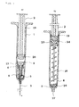
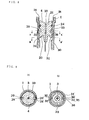
- FIGURE 1 is a cross-sectional view of an embodiment of the syringe with needle-hangaring mechanism of the present invention, where (a) and (b) show those before use and after use, respectively;
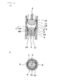
- FIGURE 2 (a) is an enlarged vertical cross-sectional view of the needle holding stopper and lock mechanism of the syringe before use shown in FIGURE 1 and (b) is an enlarged horizontal cross-sectional view of (a) taken on line A-A';
- FIGURE 3 (a) is an enlarged vertical cross-sectional view of the needle holding stopper and lock mechanism of the syringe after use shown in FIGURE 1 and (b) is an enlarged horizontal cross-sectional view of (a) taken on line A-A';
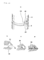
- FIGURE 4 is an enlarged cross-sectional view of the end part of the embodiment of the syringe of the present invention, where (a) and (b) show those before use and after use, respectively;
- FIGURE 5 (a) is an enlarged vertical cross-sectional view of the needle holding stopper and lock mechanism of another embodiment of the syringe of the present invention, and (b) shows an enlarged horizontal cross-sectional view of (a) taken on line A-A';
- FIGURE 6 (a) is an enlarged vertical cross-sectional view of the needle holding stopper and lock mechanism of the syringe after use shown in FIGURE 5 and (b) is an enlarged horizontal cross-sectional view of (a) taken on line A-A';
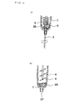
- FIGURE 7 is a cross-sectional view of a still another embodiment of the syringe with needle-hangaring mechanism of the present invention, where (a), (b) and (c) show those before use, with a medicine sucked into the barrel and with the needle having been hangared thereinto after use, respectively;
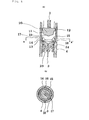
- FIGURE 8 is an enlarged cross-sectional view of the needle holding stopper and lock mechanism of the syringe shown in FIGURE 7;
- FIGURE 9 (a) and (b) are enlarged cross-sectional views taken on lines A-A' and B-B' of FIGURE 8, respectively; and
- FIGURE 10 (a) is a perspective view of the engaging part of cams provided in the syringe shown in FIGURE 7, and (b), (c) and (d) show the successive positioning of the cams.
- The present inventors have paid attention to the fact that, in handling a syringe, infection of virus or the like due to pricking of a finger with the syringe needle can only occur during the period immediately after completion of injection until completion of the disposal of the used syringe. The inventors have come to an idea of a simple mechanism utilizing a spring and capable of safely hangaring the needle into the syringe after completion of injection and, at the same time, closing the hole for mounting the needle provided on the end of the syringe, and completed the invention.
- The present invention provides a syringe with needle-hangaring mechanism comprising a
barrel 1, aplunger 2, aneedle 3, aneedle holding stopper 4, a needle hole stopper 5, aspring 6 connecting the needle holding stopper and the needle hole stopper and a lock mechanism provided between the barrel and the needle holding stopper, - the
barrel 1 comprising a forward part having a smaller inside diameter and a hinder part having a larger diameter, the two parts being connected with each other at a connectingpoint 18 having an diameter difference, - the lock mechanism functioning, in combination with the spring and the needle hole stopper, such that it holds the needle holding stopper, until completion of injection, so that the needle holding stopper is not pushed up into the hinder part of the barrel, and that it is released when the plunger is further pressed after completion of the injection, so that, by force of the spring, the needle holding stopper is pushed up, thereby hangaring the needle in the barrel, and, at the same time, the needle hole stopper is moved to stopper the needle hole on the barrel end.
- The present invention further provides concrete mechanisms for locking the needle holding stopper and for closing the needle hole.
- In the present invention, the phrase "push up" or "push down" the needle holding stopper means, in the syringe shown in, for example, FIGURE 1, the motion to move upwardly or downwardly, respectively; that is, to push up means to move from the forward part of a syringe to the hinder part and to push down means to move from the hinder part of the syringe to the forward part.
- Safety measures in handling a syringe include those against infection of virus of hepatitis or the like and against simple pricking on fingers. It would then be perfect if the needle is housed in the syringe before use, mounted by a single finger motion upon use and, after use, hangared inside the syringe again by a single finger motion so that the blood or the like adhered on the needle tip does not ooze outwardly. This, however, inevitably requires a considerably complex mechanism, which is all the more uneconomical because most syringes in recent years are of disposable type.
- When the degree of injury caused by the needle of a syringe is considered, a simple finger prick is very insignificant compared with infection of virus or the like and may be acceptable. Infection of virus or the like should be completely prevented by a mechanism which comprises hangaring the needle safely by a single finger motion, keeping the needle tip from coming outwardly again even when a strong force is applied, and preventing the blood or the like adhered to the needle chip from oozing outwardly; let remain possibility of slight finger prick. Such a mechanism, concentrating on prevention of infection, should be much simplified.
- Based on the above concept, the syringe of the present invention has been completed to simplify its mechanism significantly and is provided, in the inside of the barrel, with a movable needle holding stopper and its lock mechanism that is releasable, and with a spring which connects the needle holding stopper and the needle hole stopper, and utilizes the force of the spring to hangar the needle and close the needle hole.
- Other features of the invention will become more apparent in the course of the following descriptions of exemplary embodiments which are given for illustration of the invention and are not intended to be limiting thereof.
- Several embodiments of the present invention are concretely described by reference to the drawings.
- FIGURE 1 (a) and (b) are cross-sectional views of an embodiment of the syringe of the present invention before use and after use, respectively. The
barrel 1 andplunger 2 of the syringe are, like for conventional syringes generally used, of any material insofar as it is transparent and contains no ingredients that can dissolve out into the medicine used. In general, a plastic or glass is used for this purpose. While glass is chemically more stable than plastics, it is expensive and difficult to process into complex shapes. On the other hand, plastics are readily processable into complex shapes and inexpensive. For this reason, most disposable syringes are made of plastics in recent years. The end of the plunger is covered with a synthetic or natural rubber, a highly elastic plastic or the like to ensure high airtightness. - It is desirable that the syringe of the present invention be made of a readily processable plastic, since the syringe should be provided in the inside thereof with a mechanism for housing the needle, and that the plunger end be covered with rubber or the like to ensure high airtightness. The
barrel 1 comprises a forward part having a smaller inside diameter and a hinder part having a larger inside diameter connected with each other via apoint 18 with diameter difference. The inner surface of the hinder part of the barrel is provided with a pair ofrecesses 8 and 8' which is an element of a lock mechanism for keeping theneedle holding stopper 4, until completion of injection, from being pushed up toward the hinder part of the barrel. Astopper 19 for preventing the plunger from falling out is provided near the backward end of the barrel. - On the end of the
plunger 2 is mounted a rubber packing 20, which comprises, from the forwardest side, aconical part 10, andcylindrical parts - The
needle 3 may be similar to needles of conventional syringe, except that its length is 10 to 15 mm larger than that of conventional needles because the syringe is provided therein with a mechanism for hangaring the needle. - The
needle holding stopper 4 holds theneedle 3 and is provided with aspring support 23 for supporting one end of aspring 6, and also functions such that it is not pushed up into the hinder part of the barrel by force of the spring. Thestopper 4 is hence of complex shape and is therefore preferably a plastic molded article, the material being not specifically limited though. FIGURE 2 (a) is an enlarged cross-sectional view of an embodiment of theneedle holding stopper 4, wherein the needle is fixed by adhesion onpart 21 and the injection used enters theentrance 22 of theneedle 3 and passes through the inside of theneedle 3. The needle holding stopper contacts the inner surface of the forward part of the barrel via a packing 24. - The packing 24 is provided in order to increase the airtightness and can completely prevent the injection used from leaking into a space between the needle holding stopper and the forward end of the barrel.
- The lock mechanism comprises a pair of
recesses 8 and 8' provided on the inner surface of the syringe barrel; anelliptical lock ring 9 fit in the recesses; the packing 20 on the end of the plunger and comprising, from the forwardest side, aconical part 10, andcylindrical parts backward end 13 of the needle holding stopper. - FIGURE 2 (a) and (b) are an enlarged vertical cross-sectional view and its horizontal cross-sectional view taken on line A-A', respectively, of the lock mechanism before use, i.e. being locked. FIGURE 3 (a) and (b) are an enlarged vertical cross-sectional view and its horizontal cross-sectional view taken on line A-A', respectively, of the lock mechanism after use, i.e. being released. Before the syringe is used, the
elliptical lock ring 9 is fit in therecesses 8 and 8' provided on the inner surface of the barrel, as shown in FIGURE 2 (a). - The lock ring may be of any material insofar as it is elastic and readily deformable and does not cause, when contacted with the injection used, the injection to change in quality. For example, stainless steel and elastic plastics are usable for this purpose, the former being more preferable. The lock ring preferably has a shape of ellipse as shown in FIGURE 2 (b). The material for the lock ring may have any original shape but preferably is a thin stainless steel strip or a stainless steel wire. Among a variety of possible lock rings, particularly preferable shape is an elliptic hollow cylinder with its wall being thin and readily deformable and its side contacting the upper part of the
recesses 8 and 8' outwardly tapering a little, as shown in FIGURE 2 (a). This type of shape ensures high locking capability. - The
needle holding stopper 4 is pushed up from underneath by aspring 6 and itsupper end 13 is, as shown in the horizontal cross-sectional view of FIGURE 2 (b), stopped by the ellipse of the lock ring. To introduce a medicine into the syringe, sometimes, at first air is pressed by the syringe into a bottle containing the medicine to increase the internal pressure, which is then utilized to charge the syringe with the medicine. In this case, the internal pressure of the syringe increases when air is being introduced into the bottle. The thus increased pressure pushes the needle holding stopper down to a point where the force ofspring 6 and the internal pressure balance with each other, while the lock ring is maintained at the original position so that the lock is not released. After this operation, the internal pressure decreases, which causes the needle holding stopper to be pushed up again to reach the original position. - The plunger is then lifted up to suck the medicine into the syringe and injection is now ready. When the injection is almost complete, the end of the plunger, the lock ring and the needle holding stopper are in positions as shown in FIGURE 2 (a) and (b), like those before use. Then, further pressing of the plunger causes, as shown in FIGURE 3 (a) and (b), the
conical end 10 of the plunger contacts the minor-axis-side wall of the elliptic lock ring. When the pressing further proceeds, the elliptic lock ring is expanded to become nearly circular and is finally fit on thecylindrical part 11 of the plunger packing, whereby the lock is released. Even when the pressing still further proceeds, the lock ring fit on the packingpart 11 is stopped at thepoint 18 with diameter difference so that the lock ring shifts its position only a little and is maintained at nearly the original position. - Next, the pressing of the plunger is released. Then, while
spring 6 pushes up the needle holding stopper, the lock ring, which is fit on thepart 11 of the plunger end and hence has a decreased diameter, does not lock again when passing therecesses 8 and 8' and is pushed up to a point where the spring resumes the original form. Through the above procedure, theneedle 3 is hangared in the barrel. FIGURE 1 (b) shows how the needle is hangared in the barrel. - FIGURE 4 (a) and (b) show the conditions of the barrel end and needle hole stopper before use and after use, respectively. The
needle hole stopper 5 is provided with asmall hole 7 and aspring support 25, which is connected to thespring 6. The needle hole stopper thus has a complex shape and is hence preferably a plastic molded product, the material being not specifically limited though. Theneedle 3 is, in the original state, penetrating thesmall hole 7 of theneedle hole stopper 5 and maintained thereon. Then the needle is pushed up and gets out of the small hole. Instantaneously, the spring acts to push down the needle hole stopper so that the hole stopper rotates while being pushed down from theposition 5 to a state of 26, which closes theneedle hole 27 provided on the end of the barrel. The hole stopper is fixed in the state of 26 by action of the spring. - The
spring 6 may be of any material with no specific restrictions insofar as it is highly elastic and, when contacted with the injection used, is not damaged by corrosion or does not cause the injection to change in quality. Stainless steel and plastics are usable for this purpose, with the former being preferable. - The needle hole stopper may be of any shape that ensures closing of the needle hole when the needle is withdrawn from the small hole.
- A second embodiment of the lock mechanism used in the present invention is described next. FIGURE 5 (a) and (b) is an enlarged cross-sectional view and its horizontal cross-sectional view taken on line A-A' of the lock mechanism before use, i.e. being locked, respectively, while FIGURE 6 (a) and (b) those after use, i.e. being released.
- The lock mechanism comprises a ring-shaped
projection 14 provided on the inner surface of the hinder part of the barrel, astopper 17 comprising ahollow cylinder 15 with its thin wall inclined inwardly upwardly and at least 2small strips 16 and 16' with their tips inclined outwardly and mounted on the large diameter-side circumference of the hollow cylinder, aconical end 10 of the plunger covered with rubber packing and thebackward end 13 of the needle holding stopper. - Before use of the syringe, the
stopper 17 is engaged with the ring-shapedprojection 14 provided on the inner surface of, and having been integrally molded with, the barrel. The stopper comprises thehollow cylinder 15 with its thin wall tapering to smaller diameter upwardly and 2small strips 16 and 16' with their tips inclined outwardly and mounted on the large diameter-side circumference of the hollow cylinder and is engaged, with the part of thestrips 16 and 16' with theprojection 14. While the needle holding stopper is pressed upwardly byspring 6, thebackward end 13 of the holder is held by thecylindrical part 15 of the stopper so that it cannot be pushed up into the hinder part of the barrel. - The
stopper 17 may be of any material insofar as it is highly elastic and readily deformable and, when contacted with the injection used, does not cause the injection to change in quality. For example, stainless steel and elastic plastics are usable for this purpose, the former being more preferable. Thestopper 17 preferably has such a structure that it comprises a thin-walledhollow cylinder 15 tapering inwardly toward the hinder part of the barrel and 2strips 16 and 16' with their tips inclined outwardly and mounted on the large diameter-side circumference of the hollow cylinder. The tapered cylinder may be a slice from a hollow cone or hollow sphere, the latter being functionally more preferable. It is necessary that at least 2 pieces of the strips be mounted on the large diameter-side circumference of the hollow cylinder, and a multiplicity of such strips may be mounted. - The
needle holding stopper 4 is pressed upwardly from underneath byspring 6 and itsupper end 13 is, as shown in the horizontal cross-sectional view of FIGURE 5 (b), stopped by thecylindrical part 15 of thestopper 17. Thestrips 16 and 16' mounted on thecylindrical part 15 are engaged with the ring-shapedprojection 14. It is often the case that, in order to introduce a medicine into the syringe, prior to sucking the medicine into the syringe, air is pressed by the syringe into a bottle containing the medicine to increase the internal pressure, which is then utilized to charge the syringe with the medicine. When air is introduced into the bottle, the internal pressure of the syringe increases. The thus increased pressure pushes the needle holding stopper down to a point where the force ofspring 6 and the internal pressure balance with each other, while thestopper 17 is maintained in the original shape so that the lock is not released. After this operation and when the internal pressure decreases, the needle holding stopper is again pushed up to return to the original position. - The
plunger 2 has on its end a synthetic rubber packing 20 which comprises, from the forwardest side, aconical part 10 andcylindrical parts cone 10 of the packing causes the cylindrical part of thestopper 17 to be turned back, thereby bending thestrips 16 inwardly to cause the lock to be released. The states of the projection on the inner surface of the barrel, thestopper 17, the needle holding stopper and the end of the plunger are shown in FIGURE 6 (a) and (b). When the plunger is further pushed down, thestopper 17 on thecone part 10 of the plunger is stopped at the position ofdiameter difference 18 and is hence maintained at nearly the original position, not appreciably shifting therefrom. - Next, the force pressing the plunger is reduced. Then, while the
spring 6 pushes up the needle holding stopper, thestopper 17, with its cylindrical part still turned back and its strips still bent inwardly, passes the position of theprojection 14 without being locked again and is pushed up until the spring resumes its original shape. Through this procedure theneedle 3 is hangared in the barrel. The state of the needle thus hangared is almost the same as shown in FIGURE 1 (b). - FIGURE 7 (a) , (b) and (c) are cross-sectional views of a third embodiment of the syringe of the present invention, where (a), (b) and (c) show that before use, that with its barrel having sucked a
medicine 37 and that with the needle having been hangared in the barrel, respectively. The barrel is provided on the inner surface of its forward part arecess 28, which is part of a lock mechanism for fixing the position of theneedle holding stopper 4 and, on the inner surface of its hinder part, astopper 19 for preventing the plunged from slipping off. - The
needle holding stopper 4 has, besides the function of holding the needle, those of locking itself on the barrel and supporting one end of thespring 6. The holding stopper is hence of complex shape and is therefore preferably a plastic molded product, the material being not specifically limited though. FIGURE 8 is an enlarge cross-sectional view of an embodiment of such needle holding stopper, where the needle is fixed by adhesion onpart 21 and the injection used enters at 22 and injected through the inside of the needle. - The needle holding stopper is provided on its circumference with a pair of
projections 29 and 29' and the barrel is provided on its inner surface with a pair ofrecesses 28 and 28', as shown in FIGURE 8 and FIGURE 9 (a), which is a cross-sectional view taken on line A-A' of FIGURE 8. Theprojections 29 and 29' are engaged with therecesses 28 and 28' of the barrel and, together with the force exerted byspring 6 connected to a spring support 23 (i.e. in FIGURE 8 force pushing up from underneath), fix the position of the holding stopper. - When the
needle holding stopper 4 is pushed down, theprojections 29 contact the lower ends 32 of therecesses 28 to deform to a position of 33, thereby being disengaged from the recesses. The needle holding stopper and the barrel are provided with a pair ofcams cams edge 34 of thecam 31 moves down obliquely along the slope of 30 in the order of (b) to (c) and stops at the position of (d), during which the needle holding stopper rotates in an angle of circumference of 35 to 36. Then, when the pressure on the needle holding stopper is decreased and the stopper is pushed up by force ofspring 6, theprojections 29 no longer engage with therecesses 28, whereby the holding stopper is pushed up to a point where the spring resumes the original shape. - The
needle holding stopper 4 can, as required, be provided on its circumference with a packing 24, which increases the airtightness of the contacting part between the needle holding stopper and the inner surface of the barrel, thereby completely preventing the injection from leaking in a space between the needle holding stopper and the forward end of the barrel. - The barrel is provided with a diameter difference at a
point 18, in FIGURE 7, where the nearly top end of theneedle holding stopper 4 contacts the inner surface of the barrel. Thus, the lower part, i.e. the forward part of the syringe has a smaller inside diameter than that of the hinder part. Theend 20 of theplunger 2 contacts the barrel at its large-inside-diameter part and keeps airtightness, while theneedle holding stopper 4 contacts the barrel at its small-inside-diameter part, with the packing 24 ensuring airtightness. - After completion of injection and when the
plunger 2 is further pressed, the lock having fixed theneedle holding stopper 4 is released so that the needle holding stopper is pushed down. Then, when the force pressing the plunger is decreased, thespring 6 pushes up the needle holding stopper. On this occasion, the spring should overcome frictional resistance generating between the packing 24 of the needle holding stopper and the inner surface of the barrel and that between theend 20 of theplunger 2 and the inner surface of the barrel. Provision of theinner diameter difference 18 on the inner surface of the barrel, with the hinder part having larger inner diameter compared with the forward part, markedly reduces the frictional resistance generating between the packing 24 of the needle holding stopper and the inner surface of the barrel, while that between theend 20 of the plunger and the inner surface of the barrel does not change. - As shown in FIGURE 8, the needle holding stopper contacts, at its packing 24, with the inner surface of the small-diameter-part of the barrel and maintains good airtightness. When the needle holding stopper is pushed up by
spring 6, frictional resistance continue generating between the packing and the inner surface of the barrel until the packing reaches thepoint 18. After the packing has passed thepoint 18, there creates a clearance between the packing and the inner surface of the barrel due to the large inner diameter of the barrel there, whereby almost no friction occurs. As a result, the frictional resistance generating when the needle holding stopper and the plunger are pushed up decreases significantly. FIGURE 7 (c) shows this state. The diameter difference of thebarrel 1 is not specifically limited, but it is preferably about 1 mm for syringes for the usual purposes. - The frictional resistance generating until the packing reaches the
part 18 of the inner surface of the barrel, i.e. for an initial very short period, is the sum of that between the needle holding stopper and the barrel inner surface and that between the plunger end and the barrel inner surface, and then becomes, after the packing has passed thepart 18 of the barrel inner surface, that between the plunger end and the barrel inner surface only and hence decreases significantly, since the resistance generating between the needle holding stopper and the barrel inner surface almost vanishes there. - After completion of the injection and when the
plunger 2 is further pressed to release the lock having fixed theneedle holding stopper 4, the spring becomes in the state of its utmost compression. Consequently, when the force pressing the plunger is then reduced and the moment the spring starts pushing up the needle holding stopper and the plunger, the spring exerts the largest repulsive force. At this time, the frictional resistance against the spring is also the largest, and thereafter it decreases significantly as described above while the repulsive force of the spring gradually decreases, too. This means that the function of the spring is effectively utilized, whereby even a small spring is usable for this purpose. - Use of a small spring brings about many advantages; for example, the structural strength of the entire syringe can be decreased so that the barrel wall can be made thinner. As seen from FIGURE 8, it is desirable to make the distance between the packing 24 and the point of the
inner diameter difference 18 as short as possible, thereby minimizing the frictional resistance upon pushing up. - In the syringe of the present invention, before use, the
needle holding stopper 4 is held by a lock mechanism from being pushed up toward the hinder part of the barrel, and the needle end is generally protected with a plastic cap. When the syringe is used, after sterilization, the cap is removed from the needle and theplunger 2 is operated to suck an injection into the syringe. The injection is sucked into a space between the needle holding stopper and the plunger end and does not leak into a space between the needle holding stopper and the needle hole stopper, since sufficient airtightness is maintained at the contacting part of the needle holding stopper and the barrel inner surface. - After completion of injection, when the plunger is further pressed, the lock ring or stopper deforms to disengage the
projections 29 and 29' from therecesses 28 and 28' through action ofcams barrel 1. - Since a silicone lubricant is generally used for syringes, the above mechanism parts move markedly smoothly.
- The syringe of the present invention can, with its simple mechanism, safely hangar the needle in the barrel by a single finger motion, in order to prevent infection of virus and the like. The once hangared needle can never come out again however roughly it may be handled. Furthermore, the needle hole on the barrel end is closed so that the blood or the like of the patient adhered on the needle tip can never ooze out. The syringe further has such a structure that it is not reusable after use.
- Use of this syringe can produce a marked effect in preventing infection of the virus and the like, and so is also effective in preventing infection of AIDS, which is a large problem in the world.
- Obviously, numerous modifications and variations of the present invention are possible in light of the above teachings. It is therefore to be understood that within the scope of the appended claims, the invention may be practiced otherwise than as specifically described herein.
Claims (5)
said barrel (1) comprising a forward part having a smaller inside diameter and a hinder part having a larger diameter, said two parts being connected with each other at a connecting point (18) having an diameter difference,
said lock mechanism functioning, in combination with said spring (6) and said needle hole stopper (5), such that it holds said needle holding stopper (4), until completion of injection, so that said needle holding stopper (4) is pushed up into said hinder part of said barrel (1), and that it is released when said plunger (2) is further pressed after completion of the injection, so that, by force of said spring (6), said needle holding stopper (4) is pushed up, thereby hangaring said needle (31) in said barrel (1), and said needle hole stopper (5) is moved to stopper the needle hole (27) on the barrel end.
and functions such that:
and functions such that:
Applications Claiming Priority (2)
| Application Number | Priority Date | Filing Date | Title |
|---|---|---|---|
| JP316431/92 | 1992-10-31 | ||
| JP04316431A JP3105096B2 (en) | 1992-10-31 | 1992-10-31 | Syringe with needle tube storage mechanism |
Publications (2)
| Publication Number | Publication Date |
|---|---|
| EP0596211A1 true EP0596211A1 (en) | 1994-05-11 |
| EP0596211B1 EP0596211B1 (en) | 1998-01-21 |
Family
ID=18077008
Family Applications (1)
| Application Number | Title | Priority Date | Filing Date |
|---|---|---|---|
| EP93113851A Expired - Lifetime EP0596211B1 (en) | 1992-10-31 | 1993-08-30 | Syringe with automatic needle-withdrawal mechanism |
Country Status (6)
| Country | Link |
|---|---|
| US (1) | US5342310A (en) |
| EP (1) | EP0596211B1 (en) |
| JP (1) | JP3105096B2 (en) |
| CA (1) | CA2104758A1 (en) |
| DE (1) | DE69316532T2 (en) |
| ES (1) | ES2112936T3 (en) |
Cited By (12)
| Publication number | Priority date | Publication date | Assignee | Title |
|---|---|---|---|---|
| DE19541321A1 (en) * | 1994-11-04 | 1996-06-05 | Owen Mumford Ltd | Needle device for medical use |
| WO1998034659A1 (en) * | 1997-02-07 | 1998-08-13 | Ellingsen, Olav | Self-destructing hypodermic syringe |
| EP1184049A1 (en) * | 2000-08-30 | 2002-03-06 | Becton, Dickinson and Company | Hypodermic syringe with selectively retractable needle |
| EP1356838A1 (en) * | 2002-04-18 | 2003-10-29 | Chi-Hsuan Hsu | Self-locking disposable safety syringe having a retractable needle hub |
| WO2005072799A1 (en) * | 2004-01-20 | 2005-08-11 | Becton, Dickinson And Company | Syringe having a retractable needle |
| EP1655046A1 (en) * | 2004-11-05 | 2006-05-10 | Wei-Shui Wu | Safe syringe |
| WO2007017492A1 (en) * | 2005-08-05 | 2007-02-15 | David William Parker | Syringe with retractable needle |
| US7278986B1 (en) | 2005-03-09 | 2007-10-09 | Frost Robert J | Safety syringe with needle |
| US8167848B2 (en) | 2004-09-03 | 2012-05-01 | L.O.M. Laboratories Inc. | Single-use pneumatic safety syringe providing gas-driven needle retraction |
| CN105517606A (en) * | 2013-07-01 | 2016-04-20 | 科利登医疗系统公司 | Safety syringe |
| US10709847B2 (en) | 2015-01-20 | 2020-07-14 | L.O.M. Laboratories Inc. | Retractable needle syringe with unitary propellant release module |
| US10765815B2 (en) | 2014-10-31 | 2020-09-08 | L.O.M. Laboratories Inc. | Retractable needle syringe |
Families Citing this family (36)
| Publication number | Priority date | Publication date | Assignee | Title |
|---|---|---|---|---|
| US5613952A (en) | 1991-12-23 | 1997-03-25 | Syringe Develpoment Partners | Safety syringe |
| US5531704A (en) * | 1995-03-03 | 1996-07-02 | Emk Enterprises, Llc | Needle puncture prevention device |
| US5882337A (en) * | 1995-06-07 | 1999-03-16 | Johnson & Johnson Medical, Inc. | Tip protection device |
| US7300416B2 (en) * | 1995-08-22 | 2007-11-27 | Specialized Health Products International | Pre-filled retractable needle injection ampoules |
| US5919168A (en) * | 1997-08-25 | 1999-07-06 | Wheeler; Alton D. | Injection needle protection |
| US6569115B1 (en) * | 1997-08-28 | 2003-05-27 | Mdc Investment Holdings, Inc. | Pre-filled retractable needle injection device |
| GB2359754B (en) | 2000-03-03 | 2004-04-28 | Nmt Group Plc | Needle sheath |
| US5971964A (en) * | 1999-01-14 | 1999-10-26 | Donaldson; Neil | Retractable syringe |
| JP2000245840A (en) | 1999-03-03 | 2000-09-12 | Mitsubishi Pencil Co Ltd | Injection needle |
| US6050974A (en) * | 1999-07-13 | 2000-04-18 | Allard; Edward F. | Retractable hypodermic needle |
| US6530903B2 (en) | 2000-02-24 | 2003-03-11 | Xiping Wang | Safety syringe |
| AUPR373001A0 (en) * | 2001-03-14 | 2001-04-12 | Glenord Pty Ltd | Improved non-reusable syringe |
| US6796962B2 (en) | 2001-03-15 | 2004-09-28 | Specialized Health Products, Inc. | Safety shield for medical needles |
| US6984213B2 (en) * | 2001-03-15 | 2006-01-10 | Specialized Health Products, Inc. | Biopsy needle device |
| US6595955B2 (en) | 2001-03-15 | 2003-07-22 | Specialized Health Products, Inc. | Safety shield for medical needles |
| US7004927B2 (en) * | 2001-03-15 | 2006-02-28 | Specialized Health Products, Inc. | Safety shield for medical needles |
| US7179244B2 (en) * | 2001-03-15 | 2007-02-20 | Specialized Health Products, Inc. | Resettable safety shield for medical needles |
| US6902546B2 (en) * | 2001-03-15 | 2005-06-07 | Specialized Health Products, Inc. | Safety shield for medical needles |
| US7413562B2 (en) | 2001-03-15 | 2008-08-19 | Specialized Health Products, Inc. | Safety shield for medical needles |
| US7458954B2 (en) * | 2002-11-07 | 2008-12-02 | Specialized Health Products, Inc. | Safety shield for medical needles |
| KR100601315B1 (en) * | 2003-04-17 | 2006-07-19 | 조성구 | a safety injector structure |
| IL157981A (en) | 2003-09-17 | 2014-01-30 | Elcam Medical Agricultural Cooperative Ass Ltd | Auto-injector |
| JP4712720B2 (en) * | 2003-11-25 | 2011-06-29 | スペシャライズド・ヘルス・プロダクツ・インコーポレーテッド | Resettable safety shield for medical needles |
| MXPA06009272A (en) * | 2004-02-13 | 2007-02-02 | Smiths Medical Asd Inc | Needle tip protector. |
| IL160891A0 (en) | 2004-03-16 | 2004-08-31 | Auto-mix needle | |
| CN101437561B (en) * | 2006-03-21 | 2011-09-28 | 泰科保健集团有限合伙公司 | Passive latch ring safety shield for injection devices |
| JP5844605B2 (en) | 2011-10-31 | 2016-01-20 | 株式会社スズケン | Syringe |
| WO2013126853A2 (en) | 2012-02-23 | 2013-08-29 | Unitract Syringe Pty Ltd | Devices for targeted delivery of therapeutic implants |
| CN104582767B (en) * | 2012-02-23 | 2018-11-06 | 尤尼特拉克特注射器控股有限公司 | Bounce back needle safety syringe |
| DE102012206557A1 (en) * | 2012-04-20 | 2013-10-24 | Hans Haindl | Safety cannula for extracorporeal blood treatment |
| BR112015010607A2 (en) * | 2012-11-09 | 2017-12-05 | Iinjec Tech Inc | fluid delivery injector, retractable needle assembly, and method for injecting at least one dose of a transcutaneously fluid medication into the body. |
| WO2014107800A1 (en) * | 2013-01-11 | 2014-07-17 | Fernando Kerr Design Inc. | Needle system and method of using same |
| AU2014248541B2 (en) * | 2013-03-12 | 2018-09-13 | Unitract Syringe Pty Ltd | Retractable needle adapters and safety syringes |
| AU2014348292B2 (en) | 2013-11-15 | 2019-05-23 | Credence Medsystems Inc. | System and method for drug delivery with a safety syringe |
| CA2980443C (en) | 2014-04-24 | 2024-03-05 | Credence Medsystems Inc. | System and method for safety syringe |
| KR102124379B1 (en) * | 2017-12-20 | 2020-06-18 | 정준영 | Non-reusable disposable safety syringe |
Citations (6)
| Publication number | Priority date | Publication date | Assignee | Title |
|---|---|---|---|---|
| EP0276160A2 (en) * | 1987-01-21 | 1988-07-27 | E.R. Squibb & Sons, Inc. | Pre-filled syringe |
| WO1990006148A1 (en) * | 1988-12-01 | 1990-06-14 | Brief S.R.L. | A single-use syringe |
| US4973316A (en) * | 1990-01-16 | 1990-11-27 | Dysarz Edward D | One handed retractable safety syringe |
| US5049133A (en) * | 1989-01-24 | 1991-09-17 | Villen Pascual Joee A | Single-use safety syringe |
| US5114404A (en) * | 1990-07-24 | 1992-05-19 | Paxton Gerald R | Multifunctional retractable needle type general purpose disabling syringe having enhanced safety features and related method of operation |
| US5122118A (en) * | 1990-05-25 | 1992-06-16 | Habley Medical Technology Corporation | Automatic needle-retracting syringe |
Family Cites Families (4)
| Publication number | Priority date | Publication date | Assignee | Title |
|---|---|---|---|---|
| US4795432A (en) * | 1987-02-19 | 1989-01-03 | Karczmer Claude M | Shield assembly for hypodermic injection devices |
| US5059180A (en) * | 1989-11-21 | 1991-10-22 | Mclees Donald J | Automatic needle tip guard |
| US5147303A (en) * | 1991-05-23 | 1992-09-15 | Martin Bret C | Disposable safety syringe |
| US5195983A (en) * | 1991-08-27 | 1993-03-23 | Penta Associates | Syringe guard and disposal system |
-
1992
- 1992-10-31 JP JP04316431A patent/JP3105096B2/en not_active Expired - Fee Related
-
1993
- 1993-08-24 CA CA002104758A patent/CA2104758A1/en not_active Abandoned
- 1993-08-24 US US08/111,008 patent/US5342310A/en not_active Expired - Fee Related
- 1993-08-30 ES ES93113851T patent/ES2112936T3/en not_active Expired - Lifetime
- 1993-08-30 EP EP93113851A patent/EP0596211B1/en not_active Expired - Lifetime
- 1993-08-30 DE DE69316532T patent/DE69316532T2/en not_active Expired - Fee Related
Patent Citations (6)
| Publication number | Priority date | Publication date | Assignee | Title |
|---|---|---|---|---|
| EP0276160A2 (en) * | 1987-01-21 | 1988-07-27 | E.R. Squibb & Sons, Inc. | Pre-filled syringe |
| WO1990006148A1 (en) * | 1988-12-01 | 1990-06-14 | Brief S.R.L. | A single-use syringe |
| US5049133A (en) * | 1989-01-24 | 1991-09-17 | Villen Pascual Joee A | Single-use safety syringe |
| US4973316A (en) * | 1990-01-16 | 1990-11-27 | Dysarz Edward D | One handed retractable safety syringe |
| US5122118A (en) * | 1990-05-25 | 1992-06-16 | Habley Medical Technology Corporation | Automatic needle-retracting syringe |
| US5114404A (en) * | 1990-07-24 | 1992-05-19 | Paxton Gerald R | Multifunctional retractable needle type general purpose disabling syringe having enhanced safety features and related method of operation |
Cited By (19)
| Publication number | Priority date | Publication date | Assignee | Title |
|---|---|---|---|---|
| DE19541321A1 (en) * | 1994-11-04 | 1996-06-05 | Owen Mumford Ltd | Needle device for medical use |
| DE19541321C2 (en) * | 1994-11-04 | 2001-12-06 | Owen Mumford Ltd | Needle device for medical use |
| WO1998034659A1 (en) * | 1997-02-07 | 1998-08-13 | Ellingsen, Olav | Self-destructing hypodermic syringe |
| EP1184049A1 (en) * | 2000-08-30 | 2002-03-06 | Becton, Dickinson and Company | Hypodermic syringe with selectively retractable needle |
| US6558357B1 (en) | 2000-08-30 | 2003-05-06 | Becton Dickinson And Company | Hypodermic syringe with selectively retractable needle |
| EP1356838A1 (en) * | 2002-04-18 | 2003-10-29 | Chi-Hsuan Hsu | Self-locking disposable safety syringe having a retractable needle hub |
| WO2005072799A1 (en) * | 2004-01-20 | 2005-08-11 | Becton, Dickinson And Company | Syringe having a retractable needle |
| US9192732B2 (en) | 2004-09-03 | 2015-11-24 | L.O.M. Laboratories Inc. | Single use pneumatic safety syringe providing gas-driven needle retraction |
| US8167848B2 (en) | 2004-09-03 | 2012-05-01 | L.O.M. Laboratories Inc. | Single-use pneumatic safety syringe providing gas-driven needle retraction |
| US8523810B2 (en) | 2004-09-03 | 2013-09-03 | L.O.M. Laboratories Inc. | Single-use pneumatic safety syringe providing gas-driven needle retraction |
| US9408983B2 (en) | 2004-09-03 | 2016-08-09 | L.O.M. Laboratories Inc. | Single-use pneumatic safety syringe providing gas-driven needle retraction |
| US9649450B2 (en) | 2004-09-03 | 2017-05-16 | L.O.M. Laboratories Inc. | Single use pneumatic safety syringe providing gas-driven needle retraction |
| US10335555B2 (en) | 2004-09-03 | 2019-07-02 | L.O.M. Laboratories Inc. | Single-use pneumatic safety syringe providing gas-driven needle retraction |
| EP1655046A1 (en) * | 2004-11-05 | 2006-05-10 | Wei-Shui Wu | Safe syringe |
| US7278986B1 (en) | 2005-03-09 | 2007-10-09 | Frost Robert J | Safety syringe with needle |
| WO2007017492A1 (en) * | 2005-08-05 | 2007-02-15 | David William Parker | Syringe with retractable needle |
| CN105517606A (en) * | 2013-07-01 | 2016-04-20 | 科利登医疗系统公司 | Safety syringe |
| US10765815B2 (en) | 2014-10-31 | 2020-09-08 | L.O.M. Laboratories Inc. | Retractable needle syringe |
| US10709847B2 (en) | 2015-01-20 | 2020-07-14 | L.O.M. Laboratories Inc. | Retractable needle syringe with unitary propellant release module |
Also Published As
| Publication number | Publication date |
|---|---|
| ES2112936T3 (en) | 1998-04-16 |
| JPH06142204A (en) | 1994-05-24 |
| US5342310A (en) | 1994-08-30 |
| DE69316532D1 (en) | 1998-02-26 |
| DE69316532T2 (en) | 1998-06-18 |
| EP0596211B1 (en) | 1998-01-21 |
| CA2104758A1 (en) | 1994-05-01 |
| JP3105096B2 (en) | 2000-10-30 |
Similar Documents
| Publication | Publication Date | Title |
|---|---|---|
| EP0596211B1 (en) | Syringe with automatic needle-withdrawal mechanism | |
| CA2132277C (en) | Injection device | |
| US7090656B1 (en) | Medical devices with retractable needle | |
| US5067948A (en) | Safety, packaging, injection and disposal system for pre-filled pharmaceutical vials | |
| US5013305A (en) | Needle safety system and method | |
| EP0995455B1 (en) | Needle shield assembly | |
| US4846811A (en) | Sliding sheath for medical needles | |
| US5188599A (en) | Retractable needle system | |
| JP4875741B2 (en) | Self-actuated safety shield system for syringes | |
| US6436086B1 (en) | Method of using a safety shield assembly and related combinations thereof | |
| EP1398050A2 (en) | Needle shield assembly | |
| JPH11276582A (en) | Injector for vein | |
| US5348543A (en) | Hypodermic needle guard system | |
| US20040127856A1 (en) | Catheter and delivery end | |
| CA2265908A1 (en) | Self-retracting medical needle apparatus and methods | |
| EP1360970A1 (en) | Method for using a safety shield assembly and related combinations thereof | |
| JPH06510467A (en) | self-locking safety syringe | |
| US20050240150A1 (en) | Safety syringe | |
| US6093171A (en) | Safety syringe | |
| WO1994013336A1 (en) | Non-reusable syringe with needle guard | |
| US5021049A (en) | Needle sheath holder with seepage precluding engagement zones | |
| AU2004202713B2 (en) | Medical needle assemblies | |
| EP0425448A2 (en) | Safety cap for a medical needle after use | |
| KR101916813B1 (en) | Safety intravenous injection catheter | |
| WO1997029798A1 (en) | Device |
Legal Events
| Date | Code | Title | Description |
|---|---|---|---|
| PUAI | Public reference made under article 153(3) epc to a published international application that has entered the european phase |
Free format text: ORIGINAL CODE: 0009012 |
|
| AK | Designated contracting states |
Kind code of ref document: A1 Designated state(s): CH DE ES FR GB IT LI |
|
| 17P | Request for examination filed |
Effective date: 19941019 |
|
| 17Q | First examination report despatched |
Effective date: 19951207 |
|
| GRAG | Despatch of communication of intention to grant |
Free format text: ORIGINAL CODE: EPIDOS AGRA |
|
| GRAG | Despatch of communication of intention to grant |
Free format text: ORIGINAL CODE: EPIDOS AGRA |
|
| GRAH | Despatch of communication of intention to grant a patent |
Free format text: ORIGINAL CODE: EPIDOS IGRA |
|
| GRAH | Despatch of communication of intention to grant a patent |
Free format text: ORIGINAL CODE: EPIDOS IGRA |
|
| GRAA | (expected) grant |
Free format text: ORIGINAL CODE: 0009210 |
|
| AK | Designated contracting states |
Kind code of ref document: B1 Designated state(s): CH DE ES FR GB IT LI |
|
| PG25 | Lapsed in a contracting state [announced via postgrant information from national office to epo] |
Ref country code: LI Free format text: LAPSE BECAUSE OF FAILURE TO SUBMIT A TRANSLATION OF THE DESCRIPTION OR TO PAY THE FEE WITHIN THE PRESCRIBED TIME-LIMIT Effective date: 19980121 Ref country code: CH Free format text: LAPSE BECAUSE OF FAILURE TO SUBMIT A TRANSLATION OF THE DESCRIPTION OR TO PAY THE FEE WITHIN THE PRESCRIBED TIME-LIMIT Effective date: 19980121 |
|
| REG | Reference to a national code |
Ref country code: CH Ref legal event code: EP |
|
| REF | Corresponds to: |
Ref document number: 69316532 Country of ref document: DE Date of ref document: 19980226 |
|
| ET | Fr: translation filed | ||
| ITF | It: translation for a ep patent filed |
Owner name: SOCIETA' ITALIANA BREVETTI S.P.A. |
|
| REG | Reference to a national code |
Ref country code: ES Ref legal event code: FG2A Ref document number: 2112936 Country of ref document: ES Kind code of ref document: T3 |
|
| REG | Reference to a national code |
Ref country code: CH Ref legal event code: PL |
|
| PLBE | No opposition filed within time limit |
Free format text: ORIGINAL CODE: 0009261 |
|
| STAA | Information on the status of an ep patent application or granted ep patent |
Free format text: STATUS: NO OPPOSITION FILED WITHIN TIME LIMIT |
|
| 26N | No opposition filed | ||
| PGFP | Annual fee paid to national office [announced via postgrant information from national office to epo] |
Ref country code: ES Payment date: 19990811 Year of fee payment: 7 |
|
| PGFP | Annual fee paid to national office [announced via postgrant information from national office to epo] |
Ref country code: GB Payment date: 19990812 Year of fee payment: 7 |
|
| PGFP | Annual fee paid to national office [announced via postgrant information from national office to epo] |
Ref country code: FR Payment date: 19990817 Year of fee payment: 7 |
|
| PGFP | Annual fee paid to national office [announced via postgrant information from national office to epo] |
Ref country code: DE Payment date: 19991025 Year of fee payment: 7 |
|
| PG25 | Lapsed in a contracting state [announced via postgrant information from national office to epo] |
Ref country code: GB Free format text: LAPSE BECAUSE OF NON-PAYMENT OF DUE FEES Effective date: 20000830 |
|
| PG25 | Lapsed in a contracting state [announced via postgrant information from national office to epo] |
Ref country code: ES Free format text: LAPSE BECAUSE OF NON-PAYMENT OF DUE FEES Effective date: 20000831 |
|
| GBPC | Gb: european patent ceased through non-payment of renewal fee |
Effective date: 20000830 |
|
| PG25 | Lapsed in a contracting state [announced via postgrant information from national office to epo] |
Ref country code: FR Free format text: LAPSE BECAUSE OF NON-PAYMENT OF DUE FEES Effective date: 20010430 |
|
| PG25 | Lapsed in a contracting state [announced via postgrant information from national office to epo] |
Ref country code: DE Free format text: LAPSE BECAUSE OF NON-PAYMENT OF DUE FEES Effective date: 20010501 |
|
| REG | Reference to a national code |
Ref country code: FR Ref legal event code: ST |
|
| REG | Reference to a national code |
Ref country code: ES Ref legal event code: FD2A Effective date: 20010911 |
|
| PG25 | Lapsed in a contracting state [announced via postgrant information from national office to epo] |
Ref country code: IT Free format text: LAPSE BECAUSE OF NON-PAYMENT OF DUE FEES;WARNING: LAPSES OF ITALIAN PATENTS WITH EFFECTIVE DATE BEFORE 2007 MAY HAVE OCCURRED AT ANY TIME BEFORE 2007. THE CORRECT EFFECTIVE DATE MAY BE DIFFERENT FROM THE ONE RECORDED. Effective date: 20050830 |