EP0596545A1 - Right-angled connecting fitment for supporting wedges for fixing a pane of glass in a window formed from profiled sections - Google Patents
Right-angled connecting fitment for supporting wedges for fixing a pane of glass in a window formed from profiled sections Download PDFInfo
- Publication number
- EP0596545A1 EP0596545A1 EP93200918A EP93200918A EP0596545A1 EP 0596545 A1 EP0596545 A1 EP 0596545A1 EP 93200918 A EP93200918 A EP 93200918A EP 93200918 A EP93200918 A EP 93200918A EP 0596545 A1 EP0596545 A1 EP 0596545A1
- Authority
- EP
- European Patent Office
- Prior art keywords
- fitment
- glass
- support plate
- wedge
- window
- Prior art date
- Legal status (The legal status is an assumption and is not a legal conclusion. Google has not performed a legal analysis and makes no representation as to the accuracy of the status listed.)
- Withdrawn
Links
Images


Classifications
-
- E—FIXED CONSTRUCTIONS
- E06—DOORS, WINDOWS, SHUTTERS, OR ROLLER BLINDS IN GENERAL; LADDERS
- E06B—FIXED OR MOVABLE CLOSURES FOR OPENINGS IN BUILDINGS, VEHICLES, FENCES OR LIKE ENCLOSURES IN GENERAL, e.g. DOORS, WINDOWS, BLINDS, GATES
- E06B3/00—Window sashes, door leaves, or like elements for closing wall or like openings; Layout of fixed or moving closures, e.g. windows in wall or like openings; Features of rigidly-mounted outer frames relating to the mounting of wing frames
- E06B3/54—Fixing of glass panes or like plates
- E06B3/5409—Means for locally spacing the pane from the surrounding frame
-
- E—FIXED CONSTRUCTIONS
- E06—DOORS, WINDOWS, SHUTTERS, OR ROLLER BLINDS IN GENERAL; LADDERS
- E06B—FIXED OR MOVABLE CLOSURES FOR OPENINGS IN BUILDINGS, VEHICLES, FENCES OR LIKE ENCLOSURES IN GENERAL, e.g. DOORS, WINDOWS, BLINDS, GATES
- E06B3/00—Window sashes, door leaves, or like elements for closing wall or like openings; Layout of fixed or moving closures, e.g. windows in wall or like openings; Features of rigidly-mounted outer frames relating to the mounting of wing frames
- E06B3/96—Corner joints or edge joints for windows, doors, or the like frames or wings
- E06B3/964—Corner joints or edge joints for windows, doors, or the like frames or wings using separate connection pieces, e.g. T-connection pieces
- E06B3/968—Corner joints or edge joints for windows, doors, or the like frames or wings using separate connection pieces, e.g. T-connection pieces characterised by the way the connecting pieces are fixed in or on the frame members
- E06B3/98—Corner joints or edge joints for windows, doors, or the like frames or wings using separate connection pieces, e.g. T-connection pieces characterised by the way the connecting pieces are fixed in or on the frame members the connecting pieces being specially adapted for drawing the frame members towards each other
- E06B3/982—Mitre joints
Landscapes
- Engineering & Computer Science (AREA)
- Civil Engineering (AREA)
- Structural Engineering (AREA)
- Securing Of Glass Panes Or The Like (AREA)
Abstract
In order to enable the wedges (35, 36) which fix a pane of glass (2) in a window (1) to be positioned quickly and precisely, the invention provides a connecting fitment (26) with a right-angled body defined by two limbs (28, 29) at right angles to each other. From at least one of these latter projects at least one support plate (30, 31) part of which constitutes the wedge for the window.
Description
- The present invention relates to a fitment for fixing a pane of glass in a window frame formed from profiled metal sections.
- Windows of the type considered above are already fairly widespread and well known in all sections of the civil building industry; a technical aspect relating to them which is less recognised but has a certain importance to those working in the industry is constituted by all those devices for facilitating their assembly and putting them into operation. These operations are in fact carried out by the assembly of the various components, that is, the profiled metal sections cut to measure, the sealing strips, the handles, etc, prepared separately beforehand. Although it is now possible to make use of machines to assemble the profiled sections which constitute the frame which considerably reduces the production times, with regard to the fitting of the panes of glass in the assembled frames, the delicacy of this operation, which can readily be perceived, makes certain difficulties.
- The search for structural solutions which reduce the time needed for this phase in the window assembly thus assumes considerable importance in that this is one of the few points of improvement yet remaining in the field of windows constituted by metal profiled sections.
- At present, the insertion of a pane of glass in an assembled window frame is carried out by the fitting of a series of wedges between the edge of the pane of glass and the said frame; without explaining the reasons for the fitting of these wedges, it is relevant to note that these introduce an element of difficulty into the window assembly cycle. In fact, the workhand who has to carry out this task must fit the wedges around the window at predetermined points; this operation is not always easy in some parts of the window, for example, in the upper regions thereof and, in some circumstances, it often happens that the wedges cannot be fixed firmly to the window frame by means of the various ribs, grooves or the like on the profiled sections. All this constrains the workhand to a process of work which is long and difficult compared with the other phases in the assembly and the particular consequence is that such a solution is not satisfactory in any attempt to increase the production yield.
- The object of the present invention is to provide a fitment for the assembly of windows and, more particularly, for the fitting of a pane of glass in a window frame constituted by assembled profiled sections, which has structural and functional characteristics such as to enable the disadvantages mentioned above with reference to the prior art to be overcome.
- This object is achieved according to the invention by a fitment characterised in the claims which follow.
- Further characteristics and advantages of the invention will become more apparent from the description of one embodiment given below by way of non-limiting example, with reference to the appended drawings, in which:-
- Figure 1 is partially-sectioned perspective view of a window according to the invention;
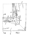
- Figure 2 shows a detail of the window of Figure 1;
- Figure 3 shows the detail of Figure 2 sectioned on the line III-III of that Figure;
- Figure 4 is a perspective view of a fitment according to the invention.
- With reference to the said drawings and in particular to Figure 1, a window according to the invention is generally indicated 1 and, in this embodiment, is of the type provided with a conventional double-
glazing pane 2. - The window 1 has a frame 5 which comprises a plurality of profiled
sections 8 connected together at right angles to each other; in a preferred embodiment, theprofiled sections 8 each have across-section 10 which includes two closed, quadrilateral-shapedcentral parts central parts - The window 1 considered above also includes two
flanges central parts - The
flange 18 is intended to serve as an abutment for the fitting of the window against its casing; since it is not relevant for the purposes of explaining the present invention, this will not be described further below. - The
flange 19 has engagement means 23, in this example constituted by a set of ribs on its surface, adapted to constitute a guide for afitment 25 of the invention. - This fitment comprises a right-
angled body 26 defined by twolimbs respective support plate support plates support plates respective limb wedges support plates - The
fitment 25 also has fixing means 38 constituted in this case by a set of grooves and ribs adapted to engage the said engagement means 23 of the profiledsections 8. To advantage, and in accordance with a preferred embodiment of the invention, the right-angled connectingfitment 25 also has anchoring means 45 and 46 in thelimbs limbs - During the assembly of the window 1 indicated above, the respective profiled
sections 8 are assembled to form the frame 5 by conventional methods. In this phase, the right-angled connectingfitment 25 is positioned with the fixing means 38 engaged with thecorresponding means 23 provided in theprofiled sections 8; more particularly, the right-angled shape of the fitment enables its twolimbs sections 8 connected at the corner of the window frame 5. - Naturally, as a result of its right-angled shape, a fitment according to the invention is located at the four corners of the window frame, that is, at the junctions of its constituent profiled sections.
- The workhand who fits the glass in the frame thus has available, at the corners of the window frame, the
support plates wedges - Furthermore, an interesting advantage offered by the present invention, in addition to that just explained, is that the right-
angled fitment 25 stiffens the connection between the two profiled sections on which it is mounted; in particular, one sees with reference to Figure 3 of the embodiment, that, in a frame for supporting two panes of glass, theprofiled sections 8 used have an elongate cross-section because of the thickness of the glass: this increases the difficulty of providing an effective connection along the entire section. - The fitment of the invention is also able to take on the function of an additional stiffening element for the connection of the profiled sections because of the presence of the anchoring means 45 and 46 with which it is provided.
- Naturally the fitment of the invention could undergo structural modifications or variations to adapt its practical details to the different operative conditions in which it may be used; clearly, in fact, the
support plates - To support this last argument, it should be noted that, it is of interest for users of a wedge to be able to adjust the position of its surface of contact with the pane of glass, as happens for example, in the above case by virtue of the cut-away surfaces and the decreasing thickness of the support plates: this is to enable the wedge to be adapted to the glass to be mounted in the window at any time and to modify the framing of the latter so as to obtain perfect geometric homogeneity of the respective frame.
- According to this teaching, the possibility of forming connecting fitments in which any
support plates - Finally then, the possibility of locating the connecting fitment in a closed-box part of the section of the profiled section should not be excluded either; to this end it would be necessary to modify the fitment by moving the support plate frontally with respect to the
respective limb limb - These and other variants which may be envisaged for changing the embodiment of the fitment considered above are, however, to be considered as falling within the scope of protection defined by the subsequent claims.
Claims (6)
1. A fitment for fixing a pane of glass (2) in a frame (5) of a window (1) formed from profiled sections (8), characterised in that it comprises a right-angled body (26) defined by two substantially coplanar limbs (28, 29) at right angles to each other provided with means (38) for engaging the profiled sections (8) of the window at a corner of the latter, at least one support plate (30, 31) projecting from at least one of the limbs (28, 29), and a part of the support plate (30, 31) and constituting a wedge (35, 36) for the fixing of the pane of glass (2).
2. A fitment according to Claim 1, characterised in that the part constituting the wedge (35, 36) is releasably associated with the support plate (30, 31).
3. A fitment according to Claim 2, characterised in that the support plate (30, 31) has an incised surface (33, 34) for engaging a corresponding wedge (35, 36) having a surface which mates with that of the support plate (30, 31), the wedge and the support plate each having a thickness which varies linearly so as to give a substantially wedge shape.
4. A fitment according to Claim 3, characterised in that it includes means (45,46) for anchoring it to the profiled sections (8) of the window frame (5) disposed in correspondence with the said limbs (28, 29).
5. A fitment according to Claim 4, characterised in that the anchoring means include a pair of threaded pins (45, 46) engaged in corresponding holes in the said limbs (28, 29).
6. A fitment according to Claim 1, characterised in that the part constituting the wedge (35, 36) is integral with the support plate (30, 31).
Applications Claiming Priority (2)
| Application Number | Priority Date | Filing Date | Title |
|---|---|---|---|
| ITMI922540 | 1992-11-05 | ||
| ITMI922540A IT1258237B (en) | 1992-11-05 | 1992-11-05 | TEAM ACCESSORY FOR THE SUPPORT OF DOWELS INTENDED FOR THE ASSEMBLY OF A GLASS SHEET IN A FRAME MADE UP OF PROFILES |
Publications (1)
| Publication Number | Publication Date |
|---|---|
| EP0596545A1 true EP0596545A1 (en) | 1994-05-11 |
Family
ID=11364239
Family Applications (1)
| Application Number | Title | Priority Date | Filing Date |
|---|---|---|---|
| EP93200918A Withdrawn EP0596545A1 (en) | 1992-11-05 | 1993-03-31 | Right-angled connecting fitment for supporting wedges for fixing a pane of glass in a window formed from profiled sections |
Country Status (2)
| Country | Link |
|---|---|
| EP (1) | EP0596545A1 (en) |
| IT (1) | IT1258237B (en) |
Cited By (8)
| Publication number | Priority date | Publication date | Assignee | Title |
|---|---|---|---|---|
| EP0745749A1 (en) * | 1995-06-02 | 1996-12-04 | Niemann, Hans Dieter | Supporting element for panes or the like |
| FR2755462A1 (en) * | 1996-11-05 | 1998-05-07 | Bezault Sa | Adjustable hinge for windows or French doors |
| GB2332694A (en) * | 1997-12-24 | 1999-06-30 | Keith John Nurcombe | Panel and frame arrangement |
| WO2000055449A1 (en) * | 1999-03-16 | 2000-09-21 | Ultraframe (Uk) Limited | Glazed roofs |
| WO2013164246A1 (en) * | 2012-04-30 | 2013-11-07 | Pro Passivhausfenster Gmbh | Passive-house window |
| WO2014194963A1 (en) * | 2013-06-07 | 2014-12-11 | Ultra-D Coöperatief U.A. | Autostereoscopic display and manufacturing thereof |
| CN104537956A (en) * | 2015-01-19 | 2015-04-22 | 北京京东方多媒体科技有限公司 | Rubber frame, display device and assembling method of display device |
| EP3342971A1 (en) * | 2016-12-30 | 2018-07-04 | SCHÜCO International KG | Window or door with a sash with a glass substrate |
Citations (5)
| Publication number | Priority date | Publication date | Assignee | Title |
|---|---|---|---|---|
| US3404501A (en) * | 1965-07-27 | 1968-10-08 | Heinz & Schuermann & Co | Holder arrangement |
| DE2044299A1 (en) * | 1970-09-08 | 1972-03-16 | Heinz Schürmann & Co, 4800 Bielefeld | Door or window |
| FR2293559A1 (en) * | 1974-12-07 | 1976-07-02 | Brendle Kurt | Door frame with adjustable wall gap - has two sections sliding against each other and obliquely positioned set screws |
| FR2417621A1 (en) * | 1978-02-16 | 1979-09-14 | Gallo Pierre | Glass pane securing assembly - uses components moved in relation to each other to vary overall thickness and grip glass edge |
| DE3419412A1 (en) * | 1984-05-24 | 1985-11-28 | Heinrich 3550 Marburg Sälzer | Frame made of one-piece frame legs |
-
1992
- 1992-11-05 IT ITMI922540A patent/IT1258237B/en active IP Right Grant
-
1993
- 1993-03-31 EP EP93200918A patent/EP0596545A1/en not_active Withdrawn
Patent Citations (5)
| Publication number | Priority date | Publication date | Assignee | Title |
|---|---|---|---|---|
| US3404501A (en) * | 1965-07-27 | 1968-10-08 | Heinz & Schuermann & Co | Holder arrangement |
| DE2044299A1 (en) * | 1970-09-08 | 1972-03-16 | Heinz Schürmann & Co, 4800 Bielefeld | Door or window |
| FR2293559A1 (en) * | 1974-12-07 | 1976-07-02 | Brendle Kurt | Door frame with adjustable wall gap - has two sections sliding against each other and obliquely positioned set screws |
| FR2417621A1 (en) * | 1978-02-16 | 1979-09-14 | Gallo Pierre | Glass pane securing assembly - uses components moved in relation to each other to vary overall thickness and grip glass edge |
| DE3419412A1 (en) * | 1984-05-24 | 1985-11-28 | Heinrich 3550 Marburg Sälzer | Frame made of one-piece frame legs |
Cited By (15)
| Publication number | Priority date | Publication date | Assignee | Title |
|---|---|---|---|---|
| EP0745749A1 (en) * | 1995-06-02 | 1996-12-04 | Niemann, Hans Dieter | Supporting element for panes or the like |
| FR2755462A1 (en) * | 1996-11-05 | 1998-05-07 | Bezault Sa | Adjustable hinge for windows or French doors |
| GB2332694A (en) * | 1997-12-24 | 1999-06-30 | Keith John Nurcombe | Panel and frame arrangement |
| GB2332694B (en) * | 1997-12-24 | 2002-10-30 | Keith John Nurcombe | Panel and frame arrangement |
| WO2000055449A1 (en) * | 1999-03-16 | 2000-09-21 | Ultraframe (Uk) Limited | Glazed roofs |
| US6301844B1 (en) | 1999-03-16 | 2001-10-16 | Ultraframe (Uk) Limited | Glazed roofs |
| WO2013164246A1 (en) * | 2012-04-30 | 2013-11-07 | Pro Passivhausfenster Gmbh | Passive-house window |
| WO2014194963A1 (en) * | 2013-06-07 | 2014-12-11 | Ultra-D Coöperatief U.A. | Autostereoscopic display and manufacturing thereof |
| TWI624692B (en) * | 2013-06-07 | 2018-05-21 | 奧崔 迪合作公司 | Autostereoscopic display and manufacturing thereof |
| CN104537956A (en) * | 2015-01-19 | 2015-04-22 | 北京京东方多媒体科技有限公司 | Rubber frame, display device and assembling method of display device |
| WO2016115886A1 (en) * | 2015-01-19 | 2016-07-28 | 京东方科技集团股份有限公司 | Rubber frame, display device and assembly method thereof |
| US9996114B2 (en) | 2015-01-19 | 2018-06-12 | Boe Technology Group Co., Ltd. | Plastic frame, display device and assembling method thereof |
| EP3342971A1 (en) * | 2016-12-30 | 2018-07-04 | SCHÜCO International KG | Window or door with a sash with a glass substrate |
| CN108266098A (en) * | 2016-12-30 | 2018-07-10 | 许克国际两合公司 | Include the window or door of the wing frame with glass supporter |
| CN108266098B (en) * | 2016-12-30 | 2021-02-23 | 许克国际两合公司 | Window or door comprising a sash frame with a glass support |
Also Published As
| Publication number | Publication date |
|---|---|
| IT1258237B (en) | 1996-02-22 |
| ITMI922540A0 (en) | 1992-11-05 |
| ITMI922540A1 (en) | 1994-05-05 |
Similar Documents
| Publication | Publication Date | Title |
|---|---|---|
| US4240765A (en) | Corner construction | |
| EP0596545A1 (en) | Right-angled connecting fitment for supporting wedges for fixing a pane of glass in a window formed from profiled sections | |
| JP3225343B2 (en) | Panel mounting structure of panel mounting frame | |
| US4462186A (en) | Self-adjusting window unit with corner assembly | |
| US4937996A (en) | Metal frame arrangements | |
| JPH02178448A (en) | Fitting device for panel member | |
| US4115964A (en) | Windows and method of making the same | |
| EP0522854A1 (en) | Forming structures | |
| GB1587379A (en) | Framing system | |
| WO1981002440A1 (en) | Joint for door frames and other similar profiles | |
| RU199347U1 (en) | Corner connection of hollow frame or window profiles | |
| JP3220046B2 (en) | Joining structure of Shoji frame | |
| JP2001311251A (en) | Curtain wall structure | |
| US5345678A (en) | Method of assembling window and glass-door casements | |
| US3472543A (en) | Method and structure for tightening secured matched abutting tubular stiles and rails by the contraction of the joined tubular members on a gusset | |
| GB2338977A (en) | Wall framing system | |
| US5816003A (en) | Clean-room wall | |
| GB1582210A (en) | Decorative frame member | |
| JP2662756B2 (en) | Panel member mounting device | |
| KR200146934Y1 (en) | Door assembling structure of double lattice winddows and doors | |
| KR800000653B1 (en) | Connecting member for window frame | |
| JPH017826Y2 (en) | ||
| JPH0248611Y2 (en) | ||
| JPH031586Y2 (en) | ||
| KR910006401Y1 (en) | Cement wing frame having mitre connection structure |
Legal Events
| Date | Code | Title | Description |
|---|---|---|---|
| PUAI | Public reference made under article 153(3) epc to a published international application that has entered the european phase |
Free format text: ORIGINAL CODE: 0009012 |
|
| AK | Designated contracting states |
Kind code of ref document: A1 Designated state(s): AT BE CH DE DK ES FR GB GR IE IT LI LU MC NL PT SE |
|
| STAA | Information on the status of an ep patent application or granted ep patent |
Free format text: STATUS: THE APPLICATION IS DEEMED TO BE WITHDRAWN |
|
| 18D | Application deemed to be withdrawn |
Effective date: 19941112 |