EP0600535A1 - A dish for containing meat, fish or the like foodstuffs - Google Patents
A dish for containing meat, fish or the like foodstuffs Download PDFInfo
- Publication number
- EP0600535A1 EP0600535A1 EP93203256A EP93203256A EP0600535A1 EP 0600535 A1 EP0600535 A1 EP 0600535A1 EP 93203256 A EP93203256 A EP 93203256A EP 93203256 A EP93203256 A EP 93203256A EP 0600535 A1 EP0600535 A1 EP 0600535A1
- Authority
- EP
- European Patent Office
- Prior art keywords
- dish
- recess
- openings
- opening
- dish according
- Prior art date
- Legal status (The legal status is an assumption and is not a legal conclusion. Google has not performed a legal analysis and makes no representation as to the accuracy of the status listed.)
- Withdrawn
Links
Images


Classifications
-
- B—PERFORMING OPERATIONS; TRANSPORTING
- B65—CONVEYING; PACKING; STORING; HANDLING THIN OR FILAMENTARY MATERIAL
- B65D—CONTAINERS FOR STORAGE OR TRANSPORT OF ARTICLES OR MATERIALS, e.g. BAGS, BARRELS, BOTTLES, BOXES, CANS, CARTONS, CRATES, DRUMS, JARS, TANKS, HOPPERS, FORWARDING CONTAINERS; ACCESSORIES, CLOSURES, OR FITTINGS THEREFOR; PACKAGING ELEMENTS; PACKAGES
- B65D81/00—Containers, packaging elements, or packages, for contents presenting particular transport or storage problems, or adapted to be used for non-packaging purposes after removal of contents
- B65D81/24—Adaptations for preventing deterioration or decay of contents; Applications to the container or packaging material of food preservatives, fungicides, pesticides or animal repellants
- B65D81/26—Adaptations for preventing deterioration or decay of contents; Applications to the container or packaging material of food preservatives, fungicides, pesticides or animal repellants with provision for draining away, or absorbing, or removing by ventilation, fluids, e.g. exuded by contents; Applications of corrosion inhibitors or desiccators
- B65D81/264—Adaptations for preventing deterioration or decay of contents; Applications to the container or packaging material of food preservatives, fungicides, pesticides or animal repellants with provision for draining away, or absorbing, or removing by ventilation, fluids, e.g. exuded by contents; Applications of corrosion inhibitors or desiccators for absorbing liquids
Definitions
- the invention relates to a dish made of expanded polystyrene for containing meat, fish or the like foodstuffs, said dish being provided with a bottom and with side walls joining said bottom and extending upwards from the bottom, whereby openings extending through the bottom are provided in said bottom, which openings are covered at the bottom side of the dish with a foil attached to the dish, which foil is impervious to liquid.
- At least one recess is provided near at least one opening in the bottom side of the dish, said recess connecting to said opening.
- the opening opens into a first part of the recess, which is in communication with a second part of the recess via a passage, whereby the two parts of the recess are separated from each other by at least one rib, which extends from a boundary edge of said recess into the recess for some distance.
- any liquid flown from the first part of the recess into the second part of the recess through the passage is prevented from flowing back, as a result of which the flow-back of liquid through the opening to the upper side of the dish is practically excluded when the dish is used in a normal manner.
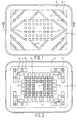
- Figure 1 is a plan view of the dish.
- Figure 2 is a bottom view of the dish.
- Figure 3 is a sectional view of the dish shown in Figure 1, along the line III-III in Figure 1.
- Figure 4 is a sectional view, corresponding with Figure 3, of a second embodiment of a dish according to the invention.
- Figure 5 is a plan view of a further embodiment of a dish according to the invention.
- Figure 6 is a bottom view of the dish shown in Figure 5.
- Figure 7 is a sectional view of Figure 6, along the line VII-VII in Figure 6.
- Figure 8 is a sectional view of Figure 7, along the line VIII-VIII in Figure 7.
- Figure 9 is a larger-scale view of a recess provided in the bottom, with ribs located therein.
- Figure 10 is a view corresponding with Figure 9, wherein the recess and the ribs located therein have a different configuration.
- Figure 11 is a sectional view of Figure 10, along the line XI-XI in Figure 10.
- Figure 12 is a view of a part of the bottom side of a further embodiment of a dish according to the invention.
- Figure 13 is a view, corresponding with Figures 9 and 10, of a recess with ribs provided therein.
- Figure 14 is a plan view of a further embodiment of a dish according to the invention.
- Figure 15 is a bottom view of the dish according to Figure 14.
- Figure 16 is a sectional view of Figure 15, along the line XVI-XVI in Figure 15.
- the dish comprises a bottom 1 and side walls 2 sloping upwards towards the outside from the circumference of the bottom.
- a number of ribs 3 slightly projecting from the bottom are provided on the upper side of the bottom.
- openings 4 extending through the bottom are provided in the bottom of the dish, whereby said openings are configured in such a manner, that the cross-section of an opening gradually increases from the top towards the bottom, as will be apparent in particular from Figure 3.
- the openings 4 are thereby arranged in rows of aligned openings, said rows extending parallel to the side walls 2.
- recesses 5 provided in the bottom side of the bottom connect to the bottom ends of the openings 4 located closest to the side walls 2, said recesses extending from the opening 4 in question in the direction of the nearest side wall 2.
- a further opening 6 corresponding with an opening 4 is provided near each corner point of the bottom.
- Three corresponding openings 7 are provided near each opening 6. The three openings 7 located near a corner point of the dish thereby lie in a straight line, which extends between the two side walls 2 bounding the corner in question.
- the illustrated embodiment is shown to have rectangular recesses 5 and 8, but it will be apparent that said recesses may also have a different configuration and/or may connect to different and/or further openings.
- the various openings provided in the bottom of the dish are covered at the bottom side of the dish by means of a foil 9 attached to the dish, said foil being impervious to liquid and preferably being made of the same plastic material as the dish.
- the openings are configured to have a rectangular section, whereby the length of one side of the opening is ⁇ 3 - 4 mm. It stands to reason that also other sectional configurations are conceivable within the spirit and scope of the invention.
- any moisture issuing from the foodstuffs can flow into the openings 4, as a result of which said moisture is carried off and disappears from sight. Said moisture will thereby be caught, at least for the greater part, in the large capacity recesses 5 and/or 8, which will prevent the undesirable flow-back of the moisture upon handling of the filled dish.
- the dishes are placed on a sloping surface, for example in counters or the like, in order to show the food products on the dishes in the best possible manner.
- the moisture will thereby tend to flow to one side of the dish.
- an additional layer 10 of an absorbing material may be provided above the impervious foil 9, as is illustrated in Figure 4, for those cases in which it is to be expected that a particularly large amount of moisture will be exuded by the food products to be contained.
- the dish shown in Figures 5 - 8 comprises a bottom 11 and side walls 12 sloping upwards towards the outside from the bottom 11.
- a number of ribs 13 slightly projecting from the bottom are provided on the upper side of the bottom.
- recesses 15 provided in the bottom side of the bottom connect to the lower ends of the openings 14 located nearest the long sides of the substantially rectangular dish, said recesses extending from the openings 14 in question in the direction of the nearest side walls 12.
- openings 16 corresponding with the openings 14 and extending through the bottom are provided near the sides of the bottom, one of said openings 16 being located near each corner point of the bottom 11.
- Each of said openings 16 opens into a substantially rectangular recess 17 provided in the bottom.
- the recesses 17 are separated from each other by boundary ribs 18 extending perpendicularly to the boundary edges of the bottom and forming part of the bottom.
- each recess 17 is divided into two parts by two ribs 19 extending into said recess, said parts being in communication with each other through a narrow passage 20, which is bounded by the free ends of the ribs 19.
- the ribs 19 in the other recesses 17 slope towards each other from their ends joining the boundary ribs 18, in a direction remote from the nearest boundary edge of the bottom.
- the inner boundary walls of said recesses comprise two parts 21 and 22 including an obtuse angle with each other.
- the various openings and recesses provided in the bottom of the dish are closed at the bottom side of the dish by means of a preferably translucent foil 23 attached to the bottom side of the dish, which foil is impervious to liquid.
- dish foodstuffs such as for example meat
- Any moisture issuing from these foodstuffs can flow through the openings 14 and 16 and be caught in the recesses 15 and 17 respectively.
- the dishes are often placed on a sloping surface, for example in counters or the like, in order to show the food products on the dishes in the best possible manner, the greater part of the moisture will thereby tend to flow into the recesses 17 through openings 16 provided near one side of the dish.
- liquid flown into parts of the recesses 17 located near the boundary edges of the bottom of the dish through the openings 16 can flow into the second parts of said recesses 17 through the passages 20.
- the obtuse-angled configuration of the boundary walls 21, 22 of the recesses located opposite the openings 16 is thereby conducive to the liquid flowing out from the openings to the second parts of the recesses 17 behind the ribs. It will be apparent that the ribs 19 will thereby oppose any subsequent flow-back of the liquid from the second parts of the recesses in the direction of the openings 16.
- Figure 10 shows an embodiment wherein the facing ends 19' of the ribs provided in a recess 17 extend parallel to each other for some distance.
- Figure 12 shows an embodiment wherein the ribs 19, which are provided in a recess 17 located in a corner point of the bottom of the dish do not extend perpendicularly to the boundary edges of the rectangular bottom, but slope towards each other at an angle with respect to said boundary edges.
- Figure 13 shows an embodiment wherein four ribs 24 are provided in a recess 17, each of said ribs extending from a boundary edge 25 of the recess 17 in a direction perpendicular to said boundary edge, and subsequently turning off in the direction of a further boundary edge joining said boundary edge 25.
- the dish is preferably manufactured in a mould of EPS hard foam, as a result of which the dish surface obtains a structure in which the moisture is retained to a certain extent.
- the foil 9 ( Figures 1 - 4) or the foil 23 ( Figures 5 - 13) continue upwards from the bottom along the outer sides of the side walls, up to the upper side of the dish in question.
- Figures 14 - 16 show a further embodiment of a dish of expanded polystyrene according to the invention. Also in this case the dish is provided with a bottom 26 and side walls 27 extending upwards from the bottom. Cam-shaped parts 28 projecting from the upper side of the bottom join the inner sides of the side walls.
- a large number of openings 29 extending through the bottom 2 are provided in the bottom 2 in a similar manner as in the preceding embodiments, the cross-section of said openings gradually increasing from the top towards the bottom.
- openings such as for example the openings 4 or 29, which have a cross-section that is wider near the bottom end of the opening than near the upper end, so that in that case the lower parts of the openings connecting to said openings form the liquid-receiving spaces.
Abstract
The invention relates to a dish made of expanded polystyrene for containing meat, fish or the like foodstuffs. The dish is provided with a bottom (1) and with side walls (2) joining said bottom (1) and extending upwards from the bottom (1). Openings (4,6) extending through the bottom (1) are provided in the bottom (1), which openings (4,6) are covered at the bottom side of the dish with a foil (9) attached to the dish, which foil (9) is impervious to liquid. A recess (5) is provided near at least one opening (4) in the bottom (1) side of the dish, which recess (5) connects to said at least one opening (4).
Description
- The invention relates to a dish made of expanded polystyrene for containing meat, fish or the like foodstuffs, said dish being provided with a bottom and with side walls joining said bottom and extending upwards from the bottom, whereby openings extending through the bottom are provided in said bottom, which openings are covered at the bottom side of the dish with a foil attached to the dish, which foil is impervious to liquid.
- When using dishes of this type it is a problem to catch the juices released by the products placed on the dish, for example meat juices, in an effective manner, so that such juices on the one hand remain out of sight as much as possible and on the other hand do not flow off upon handling of the dish.
- From European Patent No. 0 046 956 a dish of the above kind is known, whereby a layer of a hydrophilic material is provided at the bottom side of the dish in order to absorb the juices, whilst a foil which is impervious to liquid may furthermore be provided under said hydrophilic layer. In practice it has become apparent that a dish of this type does not under all circumstances fulfil its intended purpose in a satisfactory manner.
- According to the invention at least one recess is provided near at least one opening in the bottom side of the dish, said recess connecting to said opening.
- By providing such a recess an additional capacity for containing liquid moving through the openings is created in a dish of this type, where a comparatively large amount of liquid may collect, so that it is prevented that liquid remains behind on the upper side of the bottom or that said liquid will tend to flow back through the opening upon handling of the dish. Furthermore it will generally be unnecessary to provide a layer of an absorbing material under the dish, because of the comparatively large capacity obtained in this manner. By dispensing with such a layer of an absorbing material and manufacturing the dish and the foil of the same plastic material it is quite possible to recycle the dish and the foil.
- In an advantageous embodiment the opening opens into a first part of the recess, which is in communication with a second part of the recess via a passage, whereby the two parts of the recess are separated from each other by at least one rib, which extends from a boundary edge of said recess into the recess for some distance.
- By using the construction according to the invention any liquid flown from the first part of the recess into the second part of the recess through the passage is prevented from flowing back, as a result of which the flow-back of liquid through the opening to the upper side of the dish is practically excluded when the dish is used in a normal manner.
- The invention will be explained in more detail hereafter with reference to a few embodiments of a dish according to the invention illustrated in the accompanying Figures.
- Figure 1 is a plan view of the dish.
- Figure 2 is a bottom view of the dish.
- Figure 3 is a sectional view of the dish shown in Figure 1, along the line III-III in Figure 1.
- Figure 4 is a sectional view, corresponding with Figure 3, of a second embodiment of a dish according to the invention.
- Figure 5 is a plan view of a further embodiment of a dish according to the invention.
- Figure 6 is a bottom view of the dish shown in Figure 5.
- Figure 7 is a sectional view of Figure 6, along the line VII-VII in Figure 6.
- Figure 8 is a sectional view of Figure 7, along the line VIII-VIII in Figure 7.
- Figure 9 is a larger-scale view of a recess provided in the bottom, with ribs located therein.
- Figure 10 is a view corresponding with Figure 9, wherein the recess and the ribs located therein have a different configuration.
- Figure 11 is a sectional view of Figure 10, along the line XI-XI in Figure 10.
- Figure 12 is a view of a part of the bottom side of a further embodiment of a dish according to the invention.
- Figure 13 is a view, corresponding with Figures 9 and 10, of a recess with ribs provided therein.
- Figure 14 is a plan view of a further embodiment of a dish according to the invention.
- Figure 15 is a bottom view of the dish according to Figure 14.
- Figure 16 is a sectional view of Figure 15, along the line XVI-XVI in Figure 15.
- As is shown in the Figures the dish comprises a
bottom 1 andside walls 2 sloping upwards towards the outside from the circumference of the bottom. A number ofribs 3 slightly projecting from the bottom are provided on the upper side of the bottom. - Near the centre of the dish a large number of openings 4 extending through the bottom are provided in the bottom of the dish, whereby said openings are configured in such a manner, that the cross-section of an opening gradually increases from the top towards the bottom, as will be apparent in particular from Figure 3. The openings 4 are thereby arranged in rows of aligned openings, said rows extending parallel to the
side walls 2. - As is furthermore apparent from Figures 2 and 3
recesses 5 provided in the bottom side of the bottom connect to the bottom ends of the openings 4 located closest to theside walls 2, said recesses extending from the opening 4 in question in the direction of thenearest side wall 2. - A
further opening 6 corresponding with an opening 4 is provided near each corner point of the bottom. Threecorresponding openings 7 are provided near eachopening 6. The threeopenings 7 located near a corner point of the dish thereby lie in a straight line, which extends between the twoside walls 2 bounding the corner in question. - As is furthermore apparent from Figure 2 recesses 8 provided in the bottom side of the dish and extending parallel to the side walls connect on two sides to the lower ends of the
openings 7. - The illustrated embodiment is shown to have
rectangular recesses 5 and 8, but it will be apparent that said recesses may also have a different configuration and/or may connect to different and/or further openings. - The various openings provided in the bottom of the dish are covered at the bottom side of the dish by means of a
foil 9 attached to the dish, said foil being impervious to liquid and preferably being made of the same plastic material as the dish. - In the illustrated embodiment the openings are configured to have a rectangular section, whereby the length of one side of the opening is ± 3 - 4 mm. It stands to reason that also other sectional configurations are conceivable within the spirit and scope of the invention.
- When foodstuffs which exude moisture, such as for example meat, are placed on the dish, any moisture issuing from the foodstuffs can flow into the openings 4, as a result of which said moisture is carried off and disappears from sight. Said moisture will thereby be caught, at least for the greater part, in the
large capacity recesses 5 and/or 8, which will prevent the undesirable flow-back of the moisture upon handling of the filled dish. - In many cases the dishes are placed on a sloping surface, for example in counters or the like, in order to show the food products on the dishes in the best possible manner. The moisture will thereby tend to flow to one side of the dish. By providing in particular the above-described
recesses 5 and/or 8 near the sides of the dish, a large capacity for containing moisture has been obtained near the sides of the dish by means of said recesses, so that it can be ensured that moisture is carried off to the bottom side of the dishes in an adequate manner and that there is sufficient capacity for said moisture, also when the dish is placed in a sloping position. In practice it has become apparent, therefore, that once the moisture has flown out through the openings 4, said moisture no longer tends to flow back through the openings 4, partly because of the viscosity of the moisture and the large capacity of the recesses, not even when the dish is turned upside down. - Another factor which is conducive to this phenomenon is the fact that the dishes are manufactured in a mould of EPS hard foam, as a result of which the dish surface obtains a structure in which the moisture is retained to a certain extent, this in contrast to the conventional dishes, which generally have a very smooth surface.
- Generally this will not be necessary, if desired, however, an additional layer 10 of an absorbing material may be provided above the
impervious foil 9, as is illustrated in Figure 4, for those cases in which it is to be expected that a particularly large amount of moisture will be exuded by the food products to be contained. - The dish shown in Figures 5 - 8 comprises a
bottom 11 andside walls 12 sloping upwards towards the outside from thebottom 11. A number ofribs 13 slightly projecting from the bottom are provided on the upper side of the bottom. - Near the centre of the dish a large number of
openings 14 extending through the bottom are provided in the bottom of the dish, whereby said openings are configured in such a manner that the cross-section of anopening 14 gradually increases in downward direction, as will be apparent in particular from Figures 7 and 8. - As is furthermore apparent from Figure 7,
recesses 15 provided in the bottom side of the bottom connect to the lower ends of theopenings 14 located nearest the long sides of the substantially rectangular dish, said recesses extending from theopenings 14 in question in the direction of thenearest side walls 12. -
Further openings 16 corresponding with theopenings 14 and extending through the bottom are provided near the sides of the bottom, one of saidopenings 16 being located near each corner point of thebottom 11. Each of saidopenings 16 opens into a substantiallyrectangular recess 17 provided in the bottom. Therecesses 17 are separated from each other byboundary ribs 18 extending perpendicularly to the boundary edges of the bottom and forming part of the bottom. - As will furthermore be apparent from Figure 6, each
recess 17 is divided into two parts by tworibs 19 extending into said recess, said parts being in communication with each other through anarrow passage 20, which is bounded by the free ends of theribs 19. Theribs 19, which are provided in the recesses located near the corner points of the bottom, extend perpendicularly to the boundary edges of the bottom in the illustrated embodiment, as will be apparent from Figure 6. Theribs 19 in theother recesses 17 slope towards each other from their ends joining theboundary ribs 18, in a direction remote from the nearest boundary edge of the bottom. The inner boundary walls of said recesses comprise twoparts - The various openings and recesses provided in the bottom of the dish are closed at the bottom side of the dish by means of a preferably
translucent foil 23 attached to the bottom side of the dish, which foil is impervious to liquid. - When using the dish foodstuffs, such as for example meat, will be placed on the bottom of the dish. Any moisture issuing from these foodstuffs can flow through the
openings recesses - Since the dishes are often placed on a sloping surface, for example in counters or the like, in order to show the food products on the dishes in the best possible manner, the greater part of the moisture will thereby tend to flow into the
recesses 17 throughopenings 16 provided near one side of the dish. When the dish is moved, for example by a customer who wants to have a look at the food products from close by, liquid flown into parts of therecesses 17 located near the boundary edges of the bottom of the dish through theopenings 16 can flow into the second parts of saidrecesses 17 through thepassages 20. The obtuse-angled configuration of theboundary walls openings 16 is thereby conducive to the liquid flowing out from the openings to the second parts of therecesses 17 behind the ribs. It will be apparent that theribs 19 will thereby oppose any subsequent flow-back of the liquid from the second parts of the recesses in the direction of theopenings 16. In this manner a dish having a large capacity for containing liquid in therecesses 17 has been obtained, which recesses are in communication withopenings 16 provided near the sides of the bottom of the dish, whilst the flow-back of at least part of the liquid contained in therecesses 17 in the direction of theopenings 16 which open into the respective recesses is opposed as a result of the provision of theribs 19 in said recesses. - It stands to reason that variants and/or additions to the above-described construction are conceivable within the spirit and scope of the invention.
- Thus Figure 10 shows an embodiment wherein the facing ends 19' of the ribs provided in a
recess 17 extend parallel to each other for some distance. - Figure 12 shows an embodiment wherein the
ribs 19, which are provided in arecess 17 located in a corner point of the bottom of the dish do not extend perpendicularly to the boundary edges of the rectangular bottom, but slope towards each other at an angle with respect to said boundary edges. - Figure 13 shows an embodiment wherein four
ribs 24 are provided in arecess 17, each of said ribs extending from aboundary edge 25 of therecess 17 in a direction perpendicular to said boundary edge, and subsequently turning off in the direction of a further boundary edge joining saidboundary edge 25. - As was also set forth with regard to the first embodiment, the dish is preferably manufactured in a mould of EPS hard foam, as a result of which the dish surface obtains a structure in which the moisture is retained to a certain extent.
- In some cases it may also be advantageous to have the foil 9 (Figures 1 - 4) or the foil 23 (Figures 5 - 13) continue upwards from the bottom along the outer sides of the side walls, up to the upper side of the dish in question.
- Figures 14 - 16 show a further embodiment of a dish of expanded polystyrene according to the invention. Also in this case the dish is provided with a bottom 26 and
side walls 27 extending upwards from the bottom. Cam-shapedparts 28 projecting from the upper side of the bottom join the inner sides of the side walls. - A large number of
openings 29 extending through the bottom 2 are provided in the bottom 2 in a similar manner as in the preceding embodiments, the cross-section of said openings gradually increasing from the top towards the bottom. - Near the centres of the short sides of the dish
rectangular recesses 30 are provided in the bottom side of the bottom. Said recesses are in communication with a number ofopenings 31 extending through the bottom, which openings open into therecesses 30 near the edges of said recesses 30. - It will be apparent that also in this embodiment a
recess 30 is able to contain a large amount of moisture, so that also with this dish the above-described effect of the construction according to the invention will be obtained. - Furthermore it will be apparent that it will be conceivable to have a combination of recesses and openings according to the various above-described embodiments illustrated in the Figures in one single dish.
- Although recesses extending over a comparatively large area are provided in the various embodiments, it will suffice in many cases to provide only openings such as for example the
openings 4 or 29, which have a cross-section that is wider near the bottom end of the opening than near the upper end, so that in that case the lower parts of the openings connecting to said openings form the liquid-receiving spaces.
Claims (18)
- A dish made of expanded polystyrene for containing meat, fish or the like foodstuffs, said dish being provided with a bottom and with side walls joining said bottom and extending upwards from the bottom, whereby openings extending through the bottom are provided in said bottom, which openings are covered at the bottom side of the dish with a foil attached to the dish, which foil is impervious to liquid, characterized in that at least one recess is provided near at least one opening in the bottom side of the dish, said recess connecting to said opening.
- A dish according to claim 1, characterized in that a recess, which connects to an opening in the bottom side of the dish located near a side wall of the dish, is provided near said opening, said recess for the greater part being located between the respective opening and the nearest side wall.
- A dish according to claim 1 or 2, characterized in that openings are provided in the dish in rows extending parallel to the side walls, whereby a recess extending in the direction of a nearby side wall connects to each of said openings.
- A dish according to any one of the preceding claims, characterized in that openings extending through the bottom are provided near the corner points of the dish, whereby recesses provided in the bottom side of the bottom and extending parallel to the nearby side walls connect to the bottom ends of said openings.
- A dish according to claim 4, characterized in that three openings are provided near a corner point, said openings being on a line extending between side walls bounding the corner point in question, whereby recesses extending parallel to the nearby side walls connect to the bottom ends of said openings.
- A dish according to any one of the preceding claims, characterized in that said dish is formed in a mould.
- A dish according to any one of the preceding claims, characterized in that said dish and said foil are made of the same plasticmaterial.
- A dish according to any one of the preceding claims, characterized in that the cross-section of the openings increases from the upper side towards the bottom side of the dish.
- A dish according to any one of the preceding claims, characterized in that an opening opens into a first part of said recess, which is in communication with the second part of the recess via a passage, whereby the two parts of the recess are separated from each other by at least one rib, which extends from a boundary edge of said recess into the recess for some distance.
- A dish according to claim 9, characterized in that two ribs are provided in a recess, said ribs extending from the boundary edges of the recess in a direction towards each other and bounding the passage with their free ends.
- A dish according to claim 10, characterized in that said ribs extend from two opposite boundary edges of said recess in a direction towards each other.
- A dish according to any one of the preceding claims, characterized in that openings are provided near the junction between the bottom and the upright side walls, said openings being in communication with recesses which extend inwards from nearby boundary edges of the bottom, in such a manner that the two parts of said recesses are located further from the boundary edges of the bottom than the first parts of the recesses.
- A dish according to any one of the preceding claims 9 - 12, characterized in that said passage is located opposite an obtuse-angled boundary wall of the second part of the passage.
- A dish according to any one of the preceding claims 9 - 13, characterized in that an opening provided in a corner point of the bottom opens into a recess, which is divided into two parts by means of ribs, which extend transversely to boundary edges of the respective recess converging in the corner point of the bottom.
- A dish according to any one of the preceding claims 9 - 14, characterized in that an opening opens near the centre of a recess and that a few ribs join the boundary edge(s) of the recess, which ribs extend into the recess at some distance from the opening, and that each rib bounds a passage with its free end in conjunction with a part of the boundary edge(s).
- A dish according to any one of the preceding claims, characterized in that several openings connect to one recess.
- A dish according to claim 16, characterized in that near one side a recess is provided in the bottom of the dish and that several openings open into the recess near the boundary edge(s) of said recess.
- A dish according to any one of the preceding claims, characterized in that a recess is formed by a bottom part of an opening, which bottom part has a larger cross-section than the entrance of the opening.
Applications Claiming Priority (4)
| Application Number | Priority Date | Filing Date | Title |
|---|---|---|---|
| NL9202081 | 1992-12-01 | ||
| NL9202081A NL9202081A (en) | 1992-12-01 | 1992-12-01 | Tray for holding meat, fish or similar foods |
| NL9300811 | 1993-05-12 | ||
| NL9300811A NL9300811A (en) | 1993-05-12 | 1993-05-12 | Tray for holding meat, fish or similar foods |
Publications (1)
| Publication Number | Publication Date |
|---|---|
| EP0600535A1 true EP0600535A1 (en) | 1994-06-08 |
Family
ID=26647035
Family Applications (1)
| Application Number | Title | Priority Date | Filing Date |
|---|---|---|---|
| EP93203256A Withdrawn EP0600535A1 (en) | 1992-12-01 | 1993-11-22 | A dish for containing meat, fish or the like foodstuffs |
Country Status (1)
| Country | Link |
|---|---|
| EP (1) | EP0600535A1 (en) |
Cited By (6)
| Publication number | Priority date | Publication date | Assignee | Title |
|---|---|---|---|---|
| EP0690013A1 (en) | 1994-06-27 | 1996-01-03 | Synbra Technology B.V. | Plate made of a plastic foam |
| NL9401057A (en) * | 1994-06-27 | 1996-02-01 | Synbra Tech Bv | Dish made from plastic foam |
| WO2006067413A1 (en) * | 2004-12-22 | 2006-06-29 | Easy Pad Limited | Packaging tray |
| US7921992B2 (en) | 2005-11-14 | 2011-04-12 | Pactiv Corporation | Container having internal reservoir |
| US8083887B2 (en) | 2005-02-09 | 2011-12-27 | Pactiv Corporation | Method of forming a container having an internal reservoir |
| DE102013114772A1 (en) * | 2013-12-23 | 2015-07-09 | Sanner Gmbh | Container with a treatment agent and process for its preparation |
Citations (7)
| Publication number | Priority date | Publication date | Assignee | Title |
|---|---|---|---|---|
| US3341064A (en) * | 1964-11-09 | 1967-09-12 | Fausto M Ricci | Container |
| UST695195I4 (en) * | 1968-01-02 | 1969-03-25 | Robert F Anderson | Reservoir tray |
| EP0046956A1 (en) * | 1980-08-30 | 1982-03-10 | Hoechst Aktiengesellschaft | Tray-like packaging container with fluid-absorbing bottom and method for producing it |
| FR2564807A1 (en) * | 1984-05-22 | 1985-11-29 | Fraigneau Michel | Packing intended for the packaging of products exuding liquid, and for separately retaining the liquid, in all positions |
| US4576278A (en) * | 1982-11-23 | 1986-03-18 | W. R. Grace & Co., Cryovac Div. | Purge trap tray |
| CH663943A5 (en) * | 1984-09-11 | 1988-01-29 | Betan Ag | Container for foodstuff - has double floor which holds any liquid which runs off foodstuff |
| FR2614877A1 (en) * | 1987-05-07 | 1988-11-10 | Grouiller Herve | System for packaging and wrapping foodstuffs subject to exudation |
-
1993
- 1993-11-22 EP EP93203256A patent/EP0600535A1/en not_active Withdrawn
Patent Citations (7)
| Publication number | Priority date | Publication date | Assignee | Title |
|---|---|---|---|---|
| US3341064A (en) * | 1964-11-09 | 1967-09-12 | Fausto M Ricci | Container |
| UST695195I4 (en) * | 1968-01-02 | 1969-03-25 | Robert F Anderson | Reservoir tray |
| EP0046956A1 (en) * | 1980-08-30 | 1982-03-10 | Hoechst Aktiengesellschaft | Tray-like packaging container with fluid-absorbing bottom and method for producing it |
| US4576278A (en) * | 1982-11-23 | 1986-03-18 | W. R. Grace & Co., Cryovac Div. | Purge trap tray |
| FR2564807A1 (en) * | 1984-05-22 | 1985-11-29 | Fraigneau Michel | Packing intended for the packaging of products exuding liquid, and for separately retaining the liquid, in all positions |
| CH663943A5 (en) * | 1984-09-11 | 1988-01-29 | Betan Ag | Container for foodstuff - has double floor which holds any liquid which runs off foodstuff |
| FR2614877A1 (en) * | 1987-05-07 | 1988-11-10 | Grouiller Herve | System for packaging and wrapping foodstuffs subject to exudation |
Cited By (7)
| Publication number | Priority date | Publication date | Assignee | Title |
|---|---|---|---|---|
| EP0690013A1 (en) | 1994-06-27 | 1996-01-03 | Synbra Technology B.V. | Plate made of a plastic foam |
| NL9401057A (en) * | 1994-06-27 | 1996-02-01 | Synbra Tech Bv | Dish made from plastic foam |
| WO2006067413A1 (en) * | 2004-12-22 | 2006-06-29 | Easy Pad Limited | Packaging tray |
| US7762400B2 (en) | 2004-12-22 | 2010-07-27 | Easy Pad Limited | Packaging tray |
| US8083887B2 (en) | 2005-02-09 | 2011-12-27 | Pactiv Corporation | Method of forming a container having an internal reservoir |
| US7921992B2 (en) | 2005-11-14 | 2011-04-12 | Pactiv Corporation | Container having internal reservoir |
| DE102013114772A1 (en) * | 2013-12-23 | 2015-07-09 | Sanner Gmbh | Container with a treatment agent and process for its preparation |
Similar Documents
| Publication | Publication Date | Title |
|---|---|---|
| US4875620A (en) | Fluted product cup | |
| CA1136074A (en) | Individual ice cream dispensing receptacle | |
| US5887749A (en) | Food holder | |
| US5289953A (en) | Beverage service pitcher | |
| US4386700A (en) | Drain control for multiple stacked containers | |
| CA1090725A (en) | Fish box | |
| KR20210003861A (en) | Paper container with cap | |
| US4779771A (en) | Partitioned box for pouring a measured amount of a granulated solid | |
| US3937390A (en) | Fish box for storing and transporting fish | |
| EP0600535A1 (en) | A dish for containing meat, fish or the like foodstuffs | |
| AU598868B2 (en) | A bin | |
| US9314708B2 (en) | Spill-proof coloring container | |
| DE3737052C2 (en) | ||
| US5158216A (en) | Pitcher first pouring liquid at bottom | |
| EP0280023A2 (en) | Opening arrangement on packing containers | |
| CA2238459C (en) | Stackable ice tray and bin assembly | |
| US6386138B1 (en) | Spill-proof coloring container | |
| US5246149A (en) | Pitcher with an asymmetrical ice dam | |
| GB2104047A (en) | Stackable and nestable containers | |
| DE19856494C2 (en) | Tray for packaging meat portions or similar foods | |
| DE2653906A1 (en) | Cup shaped plastics vessel disposable packing for food - has joining section forming hinge between smaller and larger portion | |
| EP0474448B1 (en) | Improved fishbox | |
| CA1302374C (en) | Fluid pack with a tapered upper portion | |
| US5135138A (en) | Metering container | |
| US11856940B1 (en) | Moated system for repelling insects |
Legal Events
| Date | Code | Title | Description |
|---|---|---|---|
| PUAI | Public reference made under article 153(3) epc to a published international application that has entered the european phase |
Free format text: ORIGINAL CODE: 0009012 |
|
| AK | Designated contracting states |
Kind code of ref document: A1 Designated state(s): AT BE CH DE DK ES FR GB GR IE IT LI LU MC NL PT SE |
|
| 17P | Request for examination filed |
Effective date: 19940510 |
|
| 17Q | First examination report despatched |
Effective date: 19950901 |
|
| STAA | Information on the status of an ep patent application or granted ep patent |
Free format text: STATUS: THE APPLICATION IS DEEMED TO BE WITHDRAWN |
|
| 18D | Application deemed to be withdrawn |
Effective date: 19960112 |