EP0601686A2 - Adjustable refrigerator shelf - Google Patents
Adjustable refrigerator shelf Download PDFInfo
- Publication number
- EP0601686A2 EP0601686A2 EP93304982A EP93304982A EP0601686A2 EP 0601686 A2 EP0601686 A2 EP 0601686A2 EP 93304982 A EP93304982 A EP 93304982A EP 93304982 A EP93304982 A EP 93304982A EP 0601686 A2 EP0601686 A2 EP 0601686A2
- Authority
- EP
- European Patent Office
- Prior art keywords
- shelf
- rail
- track
- hook
- partial
- Prior art date
- Legal status (The legal status is an assumption and is not a legal conclusion. Google has not performed a legal analysis and makes no representation as to the accuracy of the status listed.)
- Granted
Links
Images


Classifications
-
- F—MECHANICAL ENGINEERING; LIGHTING; HEATING; WEAPONS; BLASTING
- F25—REFRIGERATION OR COOLING; COMBINED HEATING AND REFRIGERATION SYSTEMS; HEAT PUMP SYSTEMS; MANUFACTURE OR STORAGE OF ICE; LIQUEFACTION SOLIDIFICATION OF GASES
- F25D—REFRIGERATORS; COLD ROOMS; ICE-BOXES; COOLING OR FREEZING APPARATUS NOT OTHERWISE PROVIDED FOR
- F25D25/00—Charging, supporting, and discharging the articles to be cooled
- F25D25/02—Charging, supporting, and discharging the articles to be cooled by shelves
-
- A—HUMAN NECESSITIES
- A47—FURNITURE; DOMESTIC ARTICLES OR APPLIANCES; COFFEE MILLS; SPICE MILLS; SUCTION CLEANERS IN GENERAL
- A47B—TABLES; DESKS; OFFICE FURNITURE; CABINETS; DRAWERS; GENERAL DETAILS OF FURNITURE
- A47B57/00—Cabinets, racks or shelf units, characterised by features for adjusting shelves or partitions
- A47B57/30—Cabinets, racks or shelf units, characterised by features for adjusting shelves or partitions with means for adjusting the height of detachable shelf supports
- A47B57/40—Cabinets, racks or shelf units, characterised by features for adjusting shelves or partitions with means for adjusting the height of detachable shelf supports consisting of hooks coacting with openings
- A47B57/42—Cabinets, racks or shelf units, characterised by features for adjusting shelves or partitions with means for adjusting the height of detachable shelf supports consisting of hooks coacting with openings the shelf supports being cantilever brackets
-
- A—HUMAN NECESSITIES
- A47—FURNITURE; DOMESTIC ARTICLES OR APPLIANCES; COFFEE MILLS; SPICE MILLS; SUCTION CLEANERS IN GENERAL
- A47B—TABLES; DESKS; OFFICE FURNITURE; CABINETS; DRAWERS; GENERAL DETAILS OF FURNITURE
- A47B96/00—Details of cabinets, racks or shelf units not covered by a single one of groups A47B43/00 - A47B95/00; General details of furniture
- A47B96/06—Brackets or similar supporting means for cabinets, racks or shelves
- A47B96/061—Cantilever brackets
-
- F—MECHANICAL ENGINEERING; LIGHTING; HEATING; WEAPONS; BLASTING
- F25—REFRIGERATION OR COOLING; COMBINED HEATING AND REFRIGERATION SYSTEMS; HEAT PUMP SYSTEMS; MANUFACTURE OR STORAGE OF ICE; LIQUEFACTION SOLIDIFICATION OF GASES
- F25D—REFRIGERATORS; COLD ROOMS; ICE-BOXES; COOLING OR FREEZING APPARATUS NOT OTHERWISE PROVIDED FOR
- F25D2325/00—Charging, supporting or discharging the articles to be cooled, not provided for in other groups of this subclass
- F25D2325/022—Shelves made of glass or ceramic
-
- F—MECHANICAL ENGINEERING; LIGHTING; HEATING; WEAPONS; BLASTING
- F25—REFRIGERATION OR COOLING; COMBINED HEATING AND REFRIGERATION SYSTEMS; HEAT PUMP SYSTEMS; MANUFACTURE OR STORAGE OF ICE; LIQUEFACTION SOLIDIFICATION OF GASES
- F25D—REFRIGERATORS; COLD ROOMS; ICE-BOXES; COOLING OR FREEZING APPARATUS NOT OTHERWISE PROVIDED FOR
- F25D2331/00—Details or arrangements of other cooling or freezing apparatus not provided for in other groups of this subclass
- F25D2331/80—Type of cooled receptacles
- F25D2331/803—Bottles
-
- F—MECHANICAL ENGINEERING; LIGHTING; HEATING; WEAPONS; BLASTING
- F25—REFRIGERATION OR COOLING; COMBINED HEATING AND REFRIGERATION SYSTEMS; HEAT PUMP SYSTEMS; MANUFACTURE OR STORAGE OF ICE; LIQUEFACTION SOLIDIFICATION OF GASES
- F25D—REFRIGERATORS; COLD ROOMS; ICE-BOXES; COOLING OR FREEZING APPARATUS NOT OTHERWISE PROVIDED FOR
- F25D2500/00—Problems to be solved
- F25D2500/02—Geometry problems
Definitions
- This invention relates to shelving for refrigerators and the like.
- a basic refrigerator cabinet is typically provided with two compartments, namely a freezer compartment and a refrigerator compartment. These compartments are commonly arranged as either a “top mount” or a “side-by-side” cabinet. In the top mount arrangement, the two compartments are stacked vertically, one upon the other, and each compartment extends fully across the width of the refrigerator cabinet. In the side-by-side arrangement, each of the compartments commonly extends the full height and only partially across the width of the refrigerator cabinet. The side-by-side arrangement is a relatively more recent development to enhance storage and provide a user with a choice for refrigerated storage.
- a need is, therefore, apparent for a refrigerator shelving system which may provide desired adjustability with accompanying efficiency in utilization of refrigerator or freezer compartment space for both large and small, short and tall items.
- a shelf assembly suitable for a refrigerator comprising a shelf rail comprising attachment means allowing the rail to be mounted (e.g. releasably) in a substantially horizontal position in a refrigerator, the rail adapted to receive and support one or more shelves; and a shelf adapted to be mounted (e.g. releasably) onto the shelf rail at one of a plurality of positions along the rail.
- the shelf rail may allow the or each shelf to be slid along the shelf.
- the shelf may therefore be attached to the rail at an infinite number of locations.
- the rail may be provided with one or more stiffening and/or strengthening means.
- a second aspect of the invention relates to a refrigerator (e.g. a chamber or compartment adapted to cool, or keep coll, its contents), which includes freezers and fridge/freezers, having one or more shelf assemblies of the first aspect.
- a refrigerator e.g. a chamber or compartment adapted to cool, or keep coll, its contents
- freezers and fridge/freezers having one or more shelf assemblies of the first aspect.
- the refrigerator preferably has a refrigerated compartment with at least a first shelf track and a second shelf track mounted in the compartment, each of the first shelf track and second shelf track being generally vertically oriented in horizontally spaced relation to each other so defining a width therebetween.
- Each of the first and second shelf tracks may be adapted for releasable (e.g. supporting) engagement with a number of support brackets for cantilevered support of a number of shelves at a plurality of vertically spaced locations.
- the refrigerator has: a full shelf supported by the first and second shelf tracks which extends at least fully across the width; a shelf rail mounted on the first and second shelf tracks and extending at least fully across the width; and a partial shelf mounted on the shelf rail, the partial shelf extending less than fully across the width, the full shelf being in vertically spaced relation to the partial shelf when mounted on the shelf rail.
- the shelf rail may extend across the width and may include projecting members for releasable engagement with the first and second shelf tracks at a plurality of vertically spaced locations.
- the shelf rail may have an elongate body.
- the projecting members may extend from the elongate body and have a first hook for releasable engagement with the first shelf track and a second hook for releasable engagement with the second shelf track
- first hook and the second hook may be spaced along a length of the shelf rail.
- the shelf rail may have a first tab located near the first hook for releasable engagement with the first shelf track.
- the first tab can be adapted for locking the first hook in engagement with the first shelf track when the first tab engages the first shelf track.
- the shelf rail is rotatable about an axis of rotation for releasable engagement with each of the first and second shelf tracks, the axis of rotation extending generally along the length of the shelf rail.
- the first tab may include a first stop member (or hook) capable of releasably engaging the first shelf track to limit rotation of the shelf rail to a position in which the first tab is disengaged from and adjacent to the first shelf track.
- a first stop member or hook
- the shelf rail may have a second tab located near the second hook for releasable engagement with the second shelf track.
- This second tab may be adapted for locking the second hook in engagement with the second shelf track when the second tab engages the second shelf track.
- the second tab preferably includes a second stop member capable of releasably engaging the second shelf track to limit rotation of the shelf rail to a position in which the second tab is disengaged from, and adjacent to, the second shelf track.
- At least one of the first hook and the second hook has a leg defining a space between the leg and body, and optionally also a locking tab extending in a direction generally opposite to the leg.
- the partial shelf (which may extend less than fully across the width), can thus be cantilevered from the shelf rail and may include releasable engagement members for releasably engaging the shelf rail.
- the shelf rail may therefore have means for cooperating releasable engagement with the releasable engagement members of the partial shelf.
- the partial shelf can engage the shelf rail at a plurality of (substantially) horizontal locations.
- the partial shelf may have at least one locking hook adapted for releasable engagement with the shelf rail.
- the or each locking hook may have an elongate leg portion defining a space between the leg portion and the partial shelf for receiving a portion of the shelf rail.
- the leg portion may extend along and adjacent to a side of the shelf rail opposite the partial shelf. The leg portion may thus bear against the side and thereby limit rotation of the partial shelf relative to shelf rail.
- a wear member is interposed between the partial shelf and the shelf rail.
- the shelf rail may have a top edge extending substantially along the length of the shelf rail.
- the wear member can define an open-sided channel extending along the top edge, so the shelf rail may extend through the open side with the top edge seated within the channel.
- the partial shelf has: a shelf panel with a top surface for receiving and supporting an article set thereupon and a perimeter edge thereabout; a rim moulded from a resinous material about the perimeter edge which can provide a liquid-tight seal between the shelf panel and the rim, the liquid-tight seal suitably being formed during moulding; and at least one support bracket for supporting the partial shelf.
- the rim projects above the top surface to define a spill dam whereby a liquid disposed upon the top surface may be contained by the rim (and may not flow around the edge of the shelf panel).
- the rim can be moulded around at least a portion of the support bracket so that the shelf member and the support bracket are secured together by the rim.
- the refrigerator may further comprise a third shelf track being generally parallel to, and positioned in horizontally spaced relation to, the second shelf track, suitably on the opposite side of the second shelf track from the first shelf track. It may thus define a first width between the first shelf track and the second shelf track and a second width between the second shelf track and the third shelf track.
- the third shelf track may be adapted for releasable engagement with one or more support brackets at a plurality of vertically spaced locations.
- the shelf rail may extend across the first width and the second width and may have at least a third hook (or portion) for releasable engagement with the third shelf track. This third hook (or portion) may be spaced along the length of the shelf rail from the first hook and second hook (or portions).
- the second aspect extends to a refrigerator having a shelf rail comprising: an elongate body extending across the width and being adapted for releasably receiving and supporting a shelf; a first portion adapted for releasable engagement with said first shelf track; and a second portion, spaced along a length of the shelf rail from the first portion, adapted for releasable engagement with the second shelf track.
- the first portion may have at least a first hook for releasable engagement with the first shelf track
- the second portion can have at least a second hook for releasable engagement with the second shelf track
- the second portion may be provided with the second tab located near the second hook for releasable engagement with the second shelf track.
- This second tab may be adapted for locking the second hook in engagement with the second shelf tract when the second tab engages the second shelf track.
- the second tab may include a second stop hook capable of releasably engaging the second shelf tract to limit rotation of the shelf rail to a position in which the second tab is disengaged from, and adjacent to, the second shelf track.
- the shelf rail is adapted to receive the partial shelf at a plurality of horizontal locations.
- the second aspect also relates to a refrigerator having a refrigerated compartment comprising: a shelf rail mounted on the first and second shelf tracks and extending across the width; and a partial shelf mounted on the first and second shelf tracks and extending less than fully across the width.
- the shelf rail may have an elongate body and at least a first hook for releasable engagement with the shelf track, and at least a second hook for releasable engagement with the second shelf track, the first and second hook being spaced along a length of the shelf rail.
- the present invention seeks to provide an adjustable shelf rail to support a partial shelf in a refrigerator or freezer compartment for tiered storage of short items next to tall items in the refrigerator or freezer.
- the shelf rail is preferably releasably mountable to the horizontally spaced shelf tracks typically provided in a refrigerator, suitably at the plurality of vertically spaced positions allowed by those shelf tracks.
- the partial shelf may extend less than fully across the width of a refrigerator compartment.
- the partial shelf may be positioned horizontally at any desired location along a length of the shelf rail.
- the shelf rail is positively locked in place on the shelf tracks. Rotation of the shelf rail out of engagement with the shelf tracks can be limited by a stop hook.
- the shelf rail may also be provided with a wear member positioned between the partial shelf and the shelf rail.
- the partial shelf has a moulded, spill-resistant perimeter rim.
- the moulded rim may both maximize the spill retention capability of the shelf and minimize potential for inaccessible entrapment of a spilled material between the perimeter rim and a shelf panel of the partial shelf.
- the perimeter rim is moulded around at least a portion of a supporting shelf bracket to assure secure and durable attachment with the shelf bracket.
- the shelf support bracket may be releasably connected with the shelf rail by a locking hook which can limit rotation of the partial shelf relative to the shelf rail.
- the present invention seeks to provide enhanced refrigerator or freezer storage, to overcome inherent limitations of prior shelving systems, and furnish a shelving system which may flexibly and efficiently store both large and small, short and tall items.
- the invention is easily implemented in both existing and new shelving systems.
- FIG. 1 shows a first embodiment of a shelf assembly in a refrigerator according to the invention which has a shelf rail 20, adjustable shelf tracks 22, a full shelf 24, and a partial shelf 26.
- Adjustable shelf tracks 22 are common refrigerator or freezer hardware, vertically oriented, horizontally spaced, and mounted on a back wall 28 of a refrigerator or freezer compartment by bolts or screws as is commonly known (Figs. 2 and 15).
- Tracks 22 are typically U-shaped metal or plastic channels which include vertically spaced, aligned slots or holes 46 in their outwardly facing surfaces. The slots or holes 46 allow releasable engagement with the hook-shaped ends or flanges of shelf support brackets 30 and 32 for cantilever support of shelves 24 at various vertically spaced locations.
- shelf rail 20 is preferably formed from 14-gauge steel and subsequently powder-coated as is commonly known in the trade for refrigerator components.
- Shelf rail 20 has an elongated body 34 with rearwardly extending flanges 36 and 38 at each of two opposing ends.
- Each flange 36, 38 is provided with a pair of vertically spaced mounting hooks 40 and 42 for engaging the slots 46 provided in shelf tracks 22 (Fig. 4).
- a positive locking tab 44 is also provided on mounting hook 40 (Figs. 3 and 4). Locking tab 44 projects generally upward from mounting hook 40 to minimize accidental disengagement of shelf rail 20 from slots 46 in shelf tracks 22.
- each flange 36, 38 is provided with a mounting hook 48.
- An alternative locking tab 50 is also provided on each flange 36, 38 spaced vertically below hook 48.
- Tab 50 engages and substantially fills a track slot 46 or is at least positioned near a top edge 52 of a track slot 46.
- tab 50 has a top surface 54 adjacent top edge 52 of slot 46 so that top surface 54 will abut top edge 52 if shelf rail 20 is lifted vertically when tab 50 is engaged with shelf track 22 to preclude lifting shelf rail 20 and the disengagement and removal of mounting hook 48 from shelf track 22.
- Alternative locking tab 50 (Fig. 5) is also provided with a stop hook 56 having a leg 58.
- Leg 58 extends away from tab top surface 54 for engaging a rung 60 of shelf tracks 22 and limiting rotation of shelf rail 20 to a position in which alternative locking tab 50 is disengaged from slot 46 and positioned adjacent to shelf track 22.
- a stop 62 may be formed on and project upward from tab top surface 54 or may be omitted as shown in Figures 8 and 8A.
- Stop 62 is positioned away from rail body 34 and sized for force fit engagement of tab 50 with a slot 46 of shelf tracks 22. Thus, once shelf rail 20 is mounted on shelf tracks 22, stop 62 will resist disengagement of tab 50 from its respective slot 46. However, if shelf rail 20 is rotated to force stop 62 through slot 46 and disengage tab 50, leg 58 of stop hook 56 will engage the next lower adjoining rung 60 of shelf track 22 to positively limit further rotation of shelf rail 20 and position tab 50 adjacent to, but disengaged from, shelf track 22. Shelf rail 20 can then only be removed by lifting the entire rail and further rotating the rail to disengage tab 50 from slot 46 after which hook 48 may also be disengaged from the upper slot.
- the end flange configuration is basically similar to that shown in Figure 5 and again has a mounting hook 48 near top edge 66, a locking tab 50, and a stop hook 56 with a leg 58.
- stop 62 is omitted thereby making installation of shelf rail 20 easier, and also facilitating rotation of shelf rail 20 from a fully engaged position (Fig. 8) to a position where tab 50 is disengaged from shelf track 22 and positioned adjacent to the shelf track (Fig. 8A).
- shelf rail 20 is also formed with a stiffening ridge 64 extending between flanges 36 and 38 and projecting generally away from the mounting hooks 40, 42 (Fig. 4) or 48, 50 (Fig. 5).
- a stiffening dimple or channel may be used.
- Ridge 64 is most preferably positioned near, but spaced from, a top edge 66 of shelf rail 20. Top edge 66 may be formed by folding a portion of rail 20 forward over upon itself (see Figs. 3, 4, 5, and 16).
- Shelf rail 20 is also stiffened by top edge 66 and by forming a flange 68 along a bottom edge of shelf rail 20. Flange 68 projects in the same general direction as flanges 36 and 38 and extends along the length of shelf rail 20. Further, a recess 70 is defined between stiffening ridge 64 and top edge 66.
- a rub strip or wear member 72 is preferably provided along the length of top edge 66 of shelf rail 20 (Figs. 3 and 4).
- Rub strip 72 may be a generally U-shaped or open-sided channel member having a pair of legs 74 and 76 extending in the same general direction from a bight or web portion 78.
- Rub strip 72 may be formed from a plastics material, e.g. a high density polyethylene (HDPE) or other suitable material which is Food and Drug Administration (FDA) approved for food contact.
- HDPE high density polyethylene
- FDA Food and Drug Administration
- a ridge 80 and 82 is preferably formed at the end of each leg 74 and 76, respectively, and extends the length of rub strip 72.
- Each ridge 80 and 82 projects from its respective leg 74 and 76 in a direction generally opposite to and toward the other ridge 82, 80.
- leg 74 is sized so that ridge 80 aligns with a recess formed on a back side of and corresponding to stiffening ridge 64 while leg 76 is sized to position ridge 82 in recess 70 between stiffening ridge 64 and top edge 66.
- Rub strip 72 may thus be snapped onto and is removably secured to rail 20.
- a support 92 is bent out of and projects rearwardly from an elongated body 94 of shelf rail 90.
- Support 92 is sized in length to have a terminal end 96 closely adjacent or just in contact with refrigerator back wall 28 when shelf rail 90 is mounted on shelf tracks 22.
- Support 92 is located near an inturned flange 68 on bottom edge 98 of shelf rail 90 for supporting rail 90 to resist twisting or racking forces which may be exerted by a partial shelf 26 mounted on shelf rail 90.
- Elongated stiffening dimples 100 are also preferably provided near a top edge 102 of shelf rail 90.
- alternative shelf rail 90 also has a pair of rearwardly extending flanges 104 and 106 located at opposing ends of rail body 94.
- Each flange 104, 106 may also be configured as previously discussed in greater detail for flanges 36 and 38 of shelf rail 20 and shown in Figures 4 and 5.
- flanges 104 and 106 may also be configured in a modification of the alternative configuration shown in Figure 5 for shelf rail 20 by omitting stop 62.
- Partial shelf 26 extends only partially between shelf tracks 22.
- Partial shelf 26 may have a generally planar shelf panel 120, a pair of support brackets 122 and 124 and a moulded, resinous perimeter rim 126. Partial shelf 26 is removably mounted on and cantilevered forward from shelf rail 20 (Fig. 1).
- shelf panel 120 may be a light-transmitting material, preferably optically clear tempered glass, to enhance light distribution through the refrigerator compartment.
- Shelf panel 120 has a perimeter edge 128 which is supported above brackets 122 and 124 and positioned to overlap above inwardly projecting flange portions 130 of the brackets (Fig. 12).
- Flange portions 130 project inwardly toward each other from a top edge of generally vertical web portions 132 of each bracket 122 and 124.
- bracket 122, positioned along one side of partial shelf 26 is a mirror image of shelf bracket 124 positioned along the opposing side of partial shelf 26 (Fig. 1).
- Partial shelf 26 releasably engages shelf rail 20.
- brackets 122 and 124 are provided with a locking hook 134, having an elongated leg 136 which extends downwardly in generally parallel and spaced relation to a back edge 138 of bracket 122 (Fig. 10).
- leg 136 extends a sufficient distance along a side 140 of shelf rail 20, located opposite bracket 122, so that leg 136 bears against side 140.
- Rail 20 is thus captured between leg 136 and bracket 122 without rail 20 slipping from between leg 136 and bracket 122 to preclude rotation of partial shelf 26 relative to rail 20 when a front edge 142 of partial shelf 26 is slightly lifted for sliding partial shelf 26 along rail 20 as described in greater detail below.
- a lower portion 141 of bracket 122 is adapted for abutting engagement with shelf rail 20, near flange 68, to provide cantilever support of partial shelf 26 from shelf rail 20.
- Rim 126 is moulded around the entire perimeter edge 128 of shelf panel 120 to form a liquid-tight seal between rim 126 and shelf panel 120 and around flanges 130 of brackets 122 and 124 for secure engagement and connection of shelf panel 120 with brackets 122 and 124 (Figs. 10-12).
- Each of flanges 130 is most preferably provided with a series of perforations 144 to ensure secure mechanical connection between moulded rim 126 and each support bracket 122 and 124 (Fig. 12).
- shelf panel 120 and support brackets 122 and 124 are held and positioned within a mould while a mouldable material from which rim 126 is made is injected and flows into the mould, around peripheral edge 128 of shelf panel 120, flanges 130, and through perforations 144, encapsulating perimeter edge 128 and flanges 130.
- the mouldable material of which rim 126 is comprised may include FDA approved copolymer plastics such as a combination of ethylene and polypropylene or other structural plastic such as ABS or polyvinylchloride, for example.
- an FDA approved colouration pigment may be added to the material used for moulding rim 126 prior to moulding to provide desired colours for the rim. Titanium dioxide may be added for a white coloration, for example.
- Rim 126 is moulded to extend above the top surface 146 of shelf panel 120 and is specifically moulded to define a continuous vertical wall 148 (Figs. 11 and 12) near perimeter edge 128 of shelf panel 120 to form a spill dam for containing spills which may occur upon shelf panel 120.
- shelf support brackets 122 and 124 may be metal brackets as is shown in Figure 12 and formed from a steel, aluminium, or other metal as is commonly known for adjustable shelf support brackets
- shelf support brackets 122 and 124 may also be separate moulded plastic members 124' as shown in Figures 12A and 12B.
- shelf support brackets 124'' may also be integrally moulded with perimeter rim 126 as shown in Figures 12C and 12D.
- Shelf panel 120' may also be a separate moulded member or may be moulded in one piece with perimeter rim as shown in Figures 12B and 12D.
- Figure 12D is noted as showing all of the shelf panel, perimeter rim, and shelf support bracket moulded in one piece from the same moulded plastic material as discussed above.
- full shelf 24 extends fully between and mounts directly on shelf tracks 22 (Fig. 1). Furthermore, full shelf 24 may have a construction substantially similar to partial shelf 26 as discussed in detail above. However, instead of a hook 134 and leg 136 as on partial width shelf 26, full shelf 24 preferably includes one of the embodiments of the hooks and flanges shown and described in Figures 4-8A and 16-19 above.
- shelf rail 20 may also be used in a second shelving arrangement wherein the full width of the refrigerated compartment is divided into left and right portions by a "centre" shelf track 152.
- centred shelf track 152 may be actually centred between the outer shelf tracks 22 with shelves 154 and 156 extending between one of the outer shelf tracks 22 and the centre shelf track 152.
- centre shelf track 152 may be positioned nearer to one of shelf tracks 22 and further from the other of shelf tracks 22.
- centre shelf track 152 may comprise one shelf track, similar or identical to each shelf track 22; a pair of shelf tracks, similar or identical to each shelf track 22, positioned next to one another; a single, double wide shelf track 152 having aligned pairs of slots or holes for receiving hooks on support brackets as described and shown; or a single shelf track with wide slots adapted to receive two rails 20 or two brackets 30.
- shelf rails 20 may be staggered vertically, supporting partial shelves 26 according to a user's requirements (Fig. 15). Two shelf rails 20 may also be positioned in line with one another as specifically shown in Figure 13 so that a partial shelf 26 may be positioned to straddle centre shelf track 152.
- shelf rail 160 also preferably formed from 14-gauge steel, may be used to span the full width of the refrigerated compartment, overlaying centre shelf track 152 and mounting at its ends to shelf tracks 22.
- shelf rail 160 is most preferably configured virtually identically to shelf rail 20 with an elongated body 170 and rearwardly extending flanges 162 and 164 at each of two opposing ends (Figs. 16-18).
- each flange 162, 164 is most preferably provided with a pair of mounting hooks 166 and 168 for engaging the slots 46 provided in shelf tracks 22 and a positive locking tab 169 as previously discussed above regarding shelf rail 20 and Figure 4.
- each of the alternative rail end configurations also discussed above regarding Figures 5 and 8 may also be incorporated into rail 160.
- Shelf rail 160 also includes an elongated body 170 having a stiffening ridge 172 extending along the length of body 170 and located near a top edge 174 of shelf rail 160.
- Top edge 174 is preferably formed by bending or folding over a portion of body 170 upon itself, also as discussed above regarding top edge 66 of shelf rail 20. Top edge 174 thus provides additional stiffness to shelf rail 160 as does a flange 176 formed along a bottom edge 178 of shelf rail 160.
- a wear member or rub strip 180 as discussed in greater detail above is preferably provided on and extends along the length of top edge 174 of shelf rail 160.
- shelf rail 160 is a provision in elongated body 170 of shelf rail 160 for interconnection of shelf rail 160 with centre shelf track 152 (Figs. 16 and 19).
- a mounting hook 182 is bent rearwardly from body 170 for engagement with centre shelf track 152.
- Mounting hook 182 is therefore positioned for alignment with a slot 46 in centre shelf track 152.
- a support leg 184 is also provided and positioned in vertical alignment with mounting hook 182 and spaced vertically below mounting hook 182. While support leg 184 may be configured in a number of forms, including forms which engage a slot 46 in centre shelf track 152, support leg 184 is most preferably configured for abutting engagement with centre shelf track 152.
- Support leg 184 may thus be formed with a length sized for a terminal end 186 to abut centre shelf track 152 and is most preferably formed with a laterally extending, terminal end flange 188 positioned for abutting engagement with centre shelf track 152. With the combination of mounting hook 182 and support leg 184 engaging centre shelf track 152, shelf rail 160 is strengthened to resist twisting or racking forces which may be exerted by a partial shelf 26 mounted on shelf rail 160 and loaded.
- a pair of spaced supports 192 are bent out of and project generally rearwardly from the metal body portion 194 of the shelf rail 190.
- each support 192 is sized in length to have a terminal end closely adjacent or just in contact with refrigerator back wall 28 when shelf rail 190 is mounted on shelf tracks 22. Supports 192 thus support shelf rail 190 against twisting or racking forces as already discussed in greater detail regarding shelf rail 90.
- any of the mounting hook embodiments 40 and 42, 48 and 50, or 166 and 168 can be used on rail 190.
- a shelf rail 20 may be mounted to a pair of adjustable shelf tracks 22 (Figs. 1 and 2) or to an adjustable shelf track 22 and a centre shelf track 152 (Figs. 13 and 15) by inserting positive locking tabs 44 at each end of shelf rail 20 into a cooperating slot 46 of the adjustable shelf tracks (Fig. 4). With tabs 44 so engaged, shelf rail 20 may be rotated in a generally downward direction for insertion of mounting hooks 42 through corresponding slots 46 spaced generally vertically downwardly from the slots 46 which receive tabs 44. With tabs 44 and hooks 42 so engaged in corresponding slots 46, shelf rail 20 may be slid generally downwardly for each of mounting hooks 40 and 42 to engage a cooperating rung 60.
- a partial shelf 26 may be hung or mounted on shelf rail 20 simply by positioning leg 136 of each bracket 122 and 124 to insert wear member 72 and top edge 66 of shelf rail 20 between leg 136 and bracket back edge 138. With locking hook 134 and shelf rail 20 so engaged, lower bracket portion 141 will abut shelf rail 20 near flange 68 for cantilever support of partial shelf 26 from shelf rail 20. A generally upward force applied at front edge 142 (Fig. 10) of partial shelf 26 will release bracket lower portion 141 from abutting shelf rail 20 and allow lateral sliding of locking hook 134 along wear member 72 for lateral positioning of partial shelf 26 along the length of shelf rail 20.
- shelf rail 160 may be mounted to adjustable shelf tracks 22 with mounting hook 182 engaging centre shelf track 152 and support leg 184 abutting centre shelf track 152 (Fig. 19). Further, partial shelf 26 may similarly be releasably mounted on shelf rail 160.
- bracket lower portion 141 (Fig. 10) to extend around flange 68 for example, or full width shelves 24, 154, 156 having a width greater than the spacing between shelf tracks 22, such as across the entire refrigerator compartment, or shelf rails 20, 90, 160 or 190 extending beyond shelf tracks 22 if those tracks are not mounted at the extreme edges of the refrigerator compartment, will occur to those skilled in the art and are therefore encompassed within the invention. Therefore, it is understood that the embodiments shown in the drawings and described above are merely for illustrative purposes and are not intended to limit the scope of the invention, which is defined by the following claims.
Landscapes
- Engineering & Computer Science (AREA)
- Chemical & Material Sciences (AREA)
- Combustion & Propulsion (AREA)
- Physics & Mathematics (AREA)
- Mechanical Engineering (AREA)
- Thermal Sciences (AREA)
- General Engineering & Computer Science (AREA)
- Freezers Or Refrigerated Showcases (AREA)
- Refrigerator Housings (AREA)
Abstract
Description
- This invention relates to shelving for refrigerators and the like.
- A basic refrigerator cabinet is typically provided with two compartments, namely a freezer compartment and a refrigerator compartment. These compartments are commonly arranged as either a "top mount" or a "side-by-side" cabinet. In the top mount arrangement, the two compartments are stacked vertically, one upon the other, and each compartment extends fully across the width of the refrigerator cabinet. In the side-by-side arrangement, each of the compartments commonly extends the full height and
only partially across the width of the refrigerator cabinet. The side-by-side arrangement is a relatively more recent development to enhance storage and provide a user with a choice for refrigerated storage. - The use of shelving for refrigerators has generally evolved from providing no shelving in the freezer compartment and only fixed shelving in the refrigerated compartment to the use of vertically adjustable, tempered glass shelves, and the like, which are cantilevered from adjustable shelf tracks mounted on a back wall of each compartment. Typically, these shelves extend across the full width of the respective compartment. Particularly in top mount refrigerators, shelving and storage versatility has been further enhanced with a variety of specialty shelves, configured for specific storage tasks. The simplest and most common of these adaptations is the use of a center shelf track for supporting half width shelves in either of a left or right half of the compartment.
- While these prior advances in refrigerator shelving design may enhance refrigerated storage versatility, there is still significant inefficiency when tall beverage containers and the like are positioned on or under known refrigerator shelving. It is inherent that the spacing between refrigerator shelves is dictated by the tallest object placed on or under any given shelf. This often results in one or a few tall containers dictating a large shelf spacing with the common result of inefficient use of refrigerated space because the remainder of that shelf space is shared with shorter items. Alternatively, shorter items may be stacked or balanced upon each other in the remainder of that shelf space with the unavoidable result that these stacked items will be jostled and fall during the course of retrieval and replacement of items from the refrigerator.
- A need is, therefore, apparent for a refrigerator shelving system which may provide desired adjustability with accompanying efficiency in utilization of refrigerator or freezer compartment space for both large and small, short and tall items.
- Thus according to a first aspect of the invention there is provided a shelf assembly suitable for a refrigerator comprising a shelf rail comprising attachment means allowing the rail to be mounted (e.g. releasably) in a substantially horizontal position in a refrigerator, the rail adapted to receive and support one or more shelves; and
a shelf adapted to be mounted (e.g. releasably) onto the shelf rail at one of a plurality of positions along the rail. - The shelf rail may allow the or each shelf to be slid along the shelf. The shelf may therefore be attached to the rail at an infinite number of locations. The rail may be provided with one or more stiffening and/or strengthening means.
- A second aspect of the invention relates to a refrigerator (e.g. a chamber or compartment adapted to cool, or keep coll, its contents), which includes freezers and fridge/freezers, having one or more shelf assemblies of the first aspect.
- The refrigerator preferably has a refrigerated compartment with at least a first shelf track and a second shelf track mounted in the compartment, each of the first shelf track and second shelf track being generally vertically oriented in horizontally spaced relation to each other so defining a width therebetween. Each of the first and second shelf tracks may be adapted for releasable (e.g. supporting) engagement with a number of support brackets for cantilevered support of a number of shelves at a plurality of vertically spaced locations.
- Preferably the refrigerator has:
a full shelf supported by the first and second shelf tracks which extends at least fully across the width;
a shelf rail mounted on the first and second shelf tracks and extending at least fully across the width; and
a partial shelf mounted on the shelf rail, the partial shelf extending less than fully across the width, the full shelf being in vertically spaced relation to the partial shelf when mounted on the shelf rail. - The shelf rail may extend across the width and may include projecting members for releasable engagement with the first and second shelf tracks at a plurality of vertically spaced locations.
- The shelf rail may have an elongate body. The projecting members may extend from the elongate body and have a first hook for releasable engagement with the first shelf track and a second hook for releasable engagement with the second shelf track Thus the first hook and the second hook may be spaced along a length of the shelf rail.
- The shelf rail may have a first tab located near the first hook for releasable engagement with the first shelf track. The first tab can be adapted for locking the first hook in engagement with the first shelf track when the first tab engages the first shelf track.
- Preferably the shelf rail is rotatable about an axis of rotation for releasable engagement with each of the first and second shelf tracks, the axis of rotation extending generally along the length of the shelf rail.
- The first tab may include a first stop member (or hook) capable of releasably engaging the first shelf track to limit rotation of the shelf rail to a position in which the first tab is disengaged from and adjacent to the first shelf track.
- The shelf rail may have a second tab located near the second hook for releasable engagement with the second shelf track. This second tab may be adapted for locking the second hook in engagement with the second shelf track when the second tab engages the second shelf track. The second tab preferably includes a second stop member capable of releasably engaging the second shelf track to limit rotation of the shelf rail to a position in which the second tab is disengaged from, and adjacent to, the second shelf track.
- Suitably at least one of the first hook and the second hook has a leg defining a space between the leg and body, and optionally also a locking tab extending in a direction generally opposite to the leg.
- The partial shelf (which may extend less than fully across the width), can thus be cantilevered from the shelf rail and may include releasable engagement members for releasably engaging the shelf rail. The shelf rail may therefore have means for cooperating releasable engagement with the releasable engagement members of the partial shelf.
- Advantageously the partial shelf can engage the shelf rail at a plurality of (substantially) horizontal locations.
- The partial shelf may have at least one locking hook adapted for releasable engagement with the shelf rail. The or each locking hook may have an elongate leg portion defining a space between the leg portion and the partial shelf for receiving a portion of the shelf rail. The leg portion may extend along and adjacent to a side of the shelf rail opposite the partial shelf. The leg portion may thus bear against the side and thereby limit rotation of the partial shelf relative to shelf rail.
- Suitably a wear member is interposed between the partial shelf and the shelf rail.
- The shelf rail may have a top edge extending substantially along the length of the shelf rail. The wear member can define an open-sided channel extending along the top edge, so the shelf rail may extend through the open side with the top edge seated within the channel.
- Preferably the partial shelf has:
a shelf panel with a top surface for receiving and supporting an article set thereupon and a perimeter edge thereabout;
a rim moulded from a resinous material about the perimeter edge which can provide a liquid-tight seal between the shelf panel and the rim, the liquid-tight seal suitably being formed during moulding; and
at least one support bracket for supporting the partial shelf. - The rim projects above the top surface to define a spill dam whereby a liquid disposed upon the top surface may be contained by the rim (and may not flow around the edge of the shelf panel). The rim can be moulded around at least a portion of the support bracket so that the shelf member and the support bracket are secured together by the rim.
- In the second aspect the refrigerator may further comprise a third shelf track being generally parallel to, and positioned in horizontally spaced relation to, the second shelf track, suitably on the opposite side of the second shelf track from the first shelf track. It may thus define a first width between the first shelf track and the second shelf track and a second width between the second shelf track and the third shelf track. The third shelf track may be adapted for releasable engagement with one or more support brackets at a plurality of vertically spaced locations. The shelf rail may extend across the first width and the second width and may have at least a third hook (or portion) for releasable engagement with the third shelf track. This third hook (or portion) may be spaced along the length of the shelf rail from the first hook and second hook (or portions).
- The second aspect extends to a refrigerator having a shelf rail comprising:
an elongate body extending across the width and being adapted for releasably receiving and supporting a shelf;
a first portion adapted for releasable engagement with said first shelf track; and
a second portion, spaced along a length of the shelf rail from the first portion, adapted for releasable engagement with the second shelf track. - The first portion may have at least a first hook for releasable engagement with the first shelf track, and the second portion can have at least a second hook for releasable engagement with the second shelf track.
- The second portion may be provided with the second tab located near the second hook for releasable engagement with the second shelf track. This second tab may be adapted for locking the second hook in engagement with the second shelf tract when the second tab engages the second shelf track. The second tab may include a second stop hook capable of releasably engaging the second shelf tract to limit rotation of the shelf rail to a position in which the second tab is disengaged from, and adjacent to, the second shelf track.
- Suitably the shelf rail is adapted to receive the partial shelf at a plurality of horizontal locations.
- The second aspect also relates to a refrigerator having a refrigerated compartment comprising:
a shelf rail mounted on the first and second shelf tracks and extending across the width; and
a partial shelf mounted on the first and second shelf tracks and extending less than fully across the width. - The shelf rail may have an elongate body and at least a first hook for releasable engagement with the shelf track, and at least a second hook for releasable engagement with the second shelf track, the first and second hook being spaced along a length of the shelf rail.
- Preferred features and characteristics of one aspect are as for another mutatis mutandis.
- Accordingly, the present invention seeks to provide an adjustable shelf rail to support a partial shelf in a refrigerator or freezer compartment for tiered storage of short items next to tall items in the refrigerator or freezer. The shelf rail is preferably releasably mountable to the horizontally spaced shelf tracks typically provided in a refrigerator, suitably at the plurality of vertically spaced positions allowed by those shelf tracks. The partial shelf may extend less than fully across the width of a refrigerator compartment.
- In one embodiment the partial shelf may be positioned horizontally at any desired location along a length of the shelf rail. In another embodiment, the shelf rail is positively locked in place on the shelf tracks. Rotation of the shelf rail out of engagement with the shelf tracks can be limited by a stop hook. The shelf rail may also be provided with a wear member positioned between the partial shelf and the shelf rail.
- Preferably the partial shelf has a moulded, spill-resistant perimeter rim. The moulded rim may both maximize the spill retention capability of the shelf and minimize potential for inaccessible entrapment of a spilled material between the perimeter rim and a shelf panel of the partial shelf. Suitably the perimeter rim is moulded around at least a portion of a supporting shelf bracket to assure secure and durable attachment with the shelf bracket. The shelf support bracket may be releasably connected with the shelf rail by a locking hook which can limit rotation of the partial shelf relative to the shelf rail.
- Thus, the present invention seeks to provide enhanced refrigerator or freezer storage, to overcome inherent limitations of prior shelving systems, and furnish a shelving system which may flexibly and efficiently store both large and small, short and tall items. The invention is easily implemented in both existing and new shelving systems.
- The invention will now be described, by way of example only (and which is not to be construed as being limiting) with reference to the accompanying drawings, in which:
- Fig. 1 is a perspective view from above and to one side of a first embodiment of a (refrigerator) shelf assembly according to the present invention;
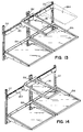
- Fig. 2 is a front elevation of the interior of a "side-by-side" refrigerator of the present invention;
- Fig. 3 is a perspective view of a shelf rail according to the present invention;
- Fig. 4 is an end elevation of the shelf rail of Fig. 3 shown mounted on a typical shelf track of the type used in refrigerator/freezer compartments;
- Fig. 5 is an end elevation similar to Fig. 4 showing an alternative shelf rail end mounted on a typical shelf track of the type used in refrigerator/freezer compartments;
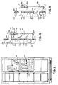
- Fig. 6 is a front elevation of a second embodiment of a shelf rail according to the present invention;
- Fig. 7 is a plan view of the shelf rail of Fig. 6;
- Fig. 8 is an end elevation, shown partially in section, of the shelf rail of Fig. 6 engaged with a shelf track;
- Fig. 8A is a view similar to Fig. 8 showing the shelf rail in a disengaged position;
- Fig. 9 is a section taken along line IX-IX of Fig. 6;
- Fig. 10 is a part section part side elevation along line X-X of Fig. 1;
- Fig. 11 is a fragmentary section along line XI-XI of Fig. 1;
- Fig. 12 is a fragmentary section along line XII-XII of Fig. 1;
- Fig. 12A is a view of a shelf similar to that in Fig. 12, but showing a plastic shelf support bracket;
- Fig. 12B is a view of a shelf similar to that in Fig. 12, but showing a plastic shelf support bracket and a perimeter rim moulded in one piece with a plastic shelf panel;
- Fig. 12C is a view of a shelf similar to that in Fig. 12, but showing the perimeter rim moulded in one piece with a plastic shelf support bracket;
- Fig. 12D is a view of a shelf similar to that in Fig. 12, but showing a perimeter rim, a plastic shelf support bracket, and a plastic shelf panel all moulded in one piece;
- Fig. 13 is a perspective view from above and to one side of a second refrigerator shelf according to the present invention;
- Fig. 14 is a perspective view from above and to one side of a third refrigerator shelf similar to that in Fig. 13, but showing a further embodiment of a shelf rail;
- Fig. 15 is a front elevational view of the interior of a top mount refrigerator showing the present invention;
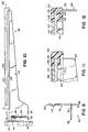
- Fig. 16 is a perspective view of a third embodiment of a shelf rail according to the present invention;
- Fig. 17 is a front elevational view of the shelf rail of Fig. 16;
- Fig. 18 is a plan view of the shelf rail of Fig. 16;
- Fig. 19 is a section along line XV-XV of Fig. 17; and
- Fig. 20 is a front elevational view of a fourth (extended length) embodiment of a shelf rail according to the present invention.
- Referring now to the drawings in greater detail, Fig. 1 shows a first embodiment of a shelf assembly in a refrigerator according to the invention which has a
shelf rail 20, adjustable shelf tracks 22, afull shelf 24, and apartial shelf 26. - Adjustable shelf tracks 22 are common refrigerator or freezer hardware, vertically oriented, horizontally spaced, and mounted on a
back wall 28 of a refrigerator or freezer compartment by bolts or screws as is commonly known (Figs. 2 and 15).Tracks 22 are typically U-shaped metal or plastic channels which include vertically spaced, aligned slots orholes 46 in their outwardly facing surfaces. The slots orholes 46 allow releasable engagement with the hook-shaped ends or flanges ofshelf support brackets shelves 24 at various vertically spaced locations. - Now referring to Figures 3 and 4, the
shelf rail 20 is preferably formed from 14-gauge steel and subsequently powder-coated as is commonly known in the trade for refrigerator components.Shelf rail 20 has an elongatedbody 34 with rearwardly extendingflanges flange slots 46 provided in shelf tracks 22 (Fig. 4). Apositive locking tab 44 is also provided on mounting hook 40 (Figs. 3 and 4). Lockingtab 44 projects generally upward from mountinghook 40 to minimize accidental disengagement ofshelf rail 20 fromslots 46 in shelf tracks 22. - In an alternative configuration of the ends of shelf rail 20 (Fig. 5), each
flange hook 48. Analternative locking tab 50 is also provided on eachflange hook 48.Tab 50 engages and substantially fills atrack slot 46 or is at least positioned near atop edge 52 of atrack slot 46. Thus,tab 50 has a top surface 54 adjacenttop edge 52 ofslot 46 so that top surface 54 will abuttop edge 52 ifshelf rail 20 is lifted vertically whentab 50 is engaged withshelf track 22 to preclude liftingshelf rail 20 and the disengagement and removal of mountinghook 48 fromshelf track 22. - Alternative locking tab 50 (Fig. 5) is also provided with a
stop hook 56 having aleg 58.Leg 58 extends away from tab top surface 54 for engaging arung 60 of shelf tracks 22 and limiting rotation ofshelf rail 20 to a position in whichalternative locking tab 50 is disengaged fromslot 46 and positioned adjacent toshelf track 22. Furthermore, a stop 62 may be formed on and project upward from tab top surface 54 or may be omitted as shown in Figures 8 and 8A. - Stop 62 is positioned away from
rail body 34 and sized for force fit engagement oftab 50 with aslot 46 of shelf tracks 22. Thus, onceshelf rail 20 is mounted on shelf tracks 22, stop 62 will resist disengagement oftab 50 from itsrespective slot 46. However, ifshelf rail 20 is rotated to force stop 62 throughslot 46 anddisengage tab 50,leg 58 ofstop hook 56 will engage the next lower adjoiningrung 60 ofshelf track 22 to positively limit further rotation ofshelf rail 20 andposition tab 50 adjacent to, but disengaged from,shelf track 22.Shelf rail 20 can then only be removed by lifting the entire rail and further rotating the rail to disengagetab 50 fromslot 46 after which hook 48 may also be disengaged from the upper slot. - In a further embodiment of the mounting hooks on
end flanges hook 48 neartop edge 66, alocking tab 50, and astop hook 56 with aleg 58. However, stop 62 is omitted thereby making installation ofshelf rail 20 easier, and also facilitating rotation ofshelf rail 20 from a fully engaged position (Fig. 8) to a position wheretab 50 is disengaged fromshelf track 22 and positioned adjacent to the shelf track (Fig. 8A). - In each embodiment,
shelf rail 20 is also formed with a stiffeningridge 64 extending betweenflanges rail embodiment 90, an indented stiffening dimple or channel may be used.Ridge 64 is most preferably positioned near, but spaced from, atop edge 66 ofshelf rail 20.Top edge 66 may be formed by folding a portion ofrail 20 forward over upon itself (see Figs. 3, 4, 5, and 16).Shelf rail 20 is also stiffened bytop edge 66 and by forming aflange 68 along a bottom edge ofshelf rail 20.Flange 68 projects in the same general direction asflanges shelf rail 20. Further, arecess 70 is defined between stiffeningridge 64 andtop edge 66. - A rub strip or wear
member 72 is preferably provided along the length oftop edge 66 of shelf rail 20 (Figs. 3 and 4).Rub strip 72 may be a generally U-shaped or open-sided channel member having a pair oflegs web portion 78.Rub strip 72 may be formed from a plastics material, e.g. a high density polyethylene (HDPE) or other suitable material which is Food and Drug Administration (FDA) approved for food contact.Rub strip 72 is preferably sized for a snug slip fit overtop edge 66 withtop edge 66 seated against the inside surface ofbight portion 78 andshelf rail body 32 extending outwardly from betweenlegs ridge 80 and 82 is preferably formed at the end of eachleg rub strip 72. Eachridge 80 and 82 projects from itsrespective leg other ridge 82, 80. Further,leg 74 is sized so that ridge 80 aligns with a recess formed on a back side of and corresponding to stiffeningridge 64 whileleg 76 is sized to positionridge 82 inrecess 70 between stiffeningridge 64 andtop edge 66.Rub strip 72 may thus be snapped onto and is removably secured to rail 20. - In an
alternative embodiment 90 ofshelf rail 20, also preferably made from 14-gauge steel as shown in Figures 6-9, asupport 92 is bent out of and projects rearwardly from anelongated body 94 ofshelf rail 90.Support 92 is sized in length to have aterminal end 96 closely adjacent or just in contact with refrigerator backwall 28 whenshelf rail 90 is mounted on shelf tracks 22.Support 92 is located near aninturned flange 68 onbottom edge 98 ofshelf rail 90 for supportingrail 90 to resist twisting or racking forces which may be exerted by apartial shelf 26 mounted onshelf rail 90. Elongated stiffeningdimples 100 are also preferably provided near atop edge 102 ofshelf rail 90. As withshelf rail 20,alternative shelf rail 90 also has a pair of rearwardly extendingflanges rail body 94. Eachflange flanges shelf rail 20 and shown in Figures 4 and 5. As shown in Figures 8 and 8A,flanges shelf rail 20 by omitting stop 62. - Now turning to
partial shelf 26 and generally to Figures 1, 10, 11, and 12-12D,partial shelf 26 extends only partially between shelf tracks 22.Partial shelf 26 may have a generallyplanar shelf panel 120, a pair ofsupport brackets resinous perimeter rim 126.Partial shelf 26 is removably mounted on and cantilevered forward from shelf rail 20 (Fig. 1). - As is best seen in Figures 11 and 12,
shelf panel 120 may be a light-transmitting material, preferably optically clear tempered glass, to enhance light distribution through the refrigerator compartment.Shelf panel 120 has aperimeter edge 128 which is supported abovebrackets flange portions 130 of the brackets (Fig. 12).Flange portions 130 project inwardly toward each other from a top edge of generallyvertical web portions 132 of eachbracket bracket 122, positioned along one side ofpartial shelf 26, is a mirror image ofshelf bracket 124 positioned along the opposing side of partial shelf 26 (Fig. 1). -
Partial shelf 26 releasably engagesshelf rail 20. Thus,brackets back edge 138 of bracket 122 (Fig. 10). Whenpartial shelf 26 is mounted to rail 20, leg 136 extends a sufficient distance along aside 140 ofshelf rail 20, located oppositebracket 122, so that leg 136 bears againstside 140.Rail 20 is thus captured between leg 136 andbracket 122 withoutrail 20 slipping from between leg 136 andbracket 122 to preclude rotation ofpartial shelf 26 relative to rail 20 when afront edge 142 ofpartial shelf 26 is slightly lifted for slidingpartial shelf 26 alongrail 20 as described in greater detail below. Finally, alower portion 141 ofbracket 122 is adapted for abutting engagement withshelf rail 20, nearflange 68, to provide cantilever support ofpartial shelf 26 fromshelf rail 20. -
Rim 126 is moulded around theentire perimeter edge 128 ofshelf panel 120 to form a liquid-tight seal betweenrim 126 andshelf panel 120 and aroundflanges 130 ofbrackets shelf panel 120 withbrackets 122 and 124 (Figs. 10-12). Each offlanges 130 is most preferably provided with a series ofperforations 144 to ensure secure mechanical connection between mouldedrim 126 and eachsupport bracket 122 and 124 (Fig. 12). During assembly,shelf panel 120 andsupport brackets peripheral edge 128 ofshelf panel 120,flanges 130, and throughperforations 144, encapsulatingperimeter edge 128 andflanges 130. The mouldable material of which rim 126 is comprised may include FDA approved copolymer plastics such as a combination of ethylene and polypropylene or other structural plastic such as ABS or polyvinylchloride, for example. Further, an FDA approved colouration pigment may be added to the material used formoulding rim 126 prior to moulding to provide desired colours for the rim. Titanium dioxide may be added for a white coloration, for example. - As the mouldable material cures, i.e. cools, hardens, and sets up, it becomes a tough and resilient mass extending continuously around
perimeter edge 128 ofshelf panel 120 for holdingshelf panel 120 in position aboveflanges 130 ofsupport brackets flanges 130 provides secure, stable support forshelf panel 120.Rim 126 is moulded to extend above thetop surface 146 ofshelf panel 120 and is specifically moulded to define a continuous vertical wall 148 (Figs. 11 and 12) nearperimeter edge 128 ofshelf panel 120 to form a spill dam for containing spills which may occur uponshelf panel 120. - While the seal formed between
rim 126 andshelf panel 120 by mouldingrim 126 aroundshelf panel 120 performs quite satisfactorily, depending upon the specific rim material chosen, one may enhance the seal by coatingperimeter edge 128 and adjoining top 146 and bottom 150 surfaces ofshelf panel 120,adjacent perimeter edge 128, prior tomoulding rim 126 thereabout, with a primer layer or coating of a heat-activatable material which promotes and facilitates adhesion and bonding of the rim material toshelf panel 120. - While the
shelf support brackets shelf support brackets perimeter rim 126 as shown in Figures 12C and 12D. Shelf panel 120' may also be a separate moulded member or may be moulded in one piece with perimeter rim as shown in Figures 12B and 12D. Figure 12D is noted as showing all of the shelf panel, perimeter rim, and shelf support bracket moulded in one piece from the same moulded plastic material as discussed above. - The
full shelf 24 extends fully between and mounts directly on shelf tracks 22 (Fig. 1). Furthermore,full shelf 24 may have a construction substantially similar topartial shelf 26 as discussed in detail above. However, instead of a hook 134 and leg 136 as onpartial width shelf 26,full shelf 24 preferably includes one of the embodiments of the hooks and flanges shown and described in Figures 4-8A and 16-19 above. - As shown in Figures 13 and 15,
shelf rail 20 may also be used in a second shelving arrangement wherein the full width of the refrigerated compartment is divided into left and right portions by a "centre"shelf track 152. In these arrangements,centred shelf track 152 may be actually centred between the outer shelf tracks 22 withshelves centre shelf track 152. Alternatively,centre shelf track 152 may be positioned nearer to one of shelf tracks 22 and further from the other of shelf tracks 22. Furthermore,centre shelf track 152 may comprise one shelf track, similar or identical to eachshelf track 22; a pair of shelf tracks, similar or identical to eachshelf track 22, positioned next to one another; a single, doublewide shelf track 152 having aligned pairs of slots or holes for receiving hooks on support brackets as described and shown; or a single shelf track with wide slots adapted to receive tworails 20 or twobrackets 30. - In the second shelving arrangement (Fig. 13), shelf rails 20 may be staggered vertically, supporting
partial shelves 26 according to a user's requirements (Fig. 15). Two shelf rails 20 may also be positioned in line with one another as specifically shown in Figure 13 so that apartial shelf 26 may be positioned to straddlecentre shelf track 152. - Alternatively, as specifically shown in Figure 14, a single, extended
length shelf rail 160, also preferably formed from 14-gauge steel, may be used to span the full width of the refrigerated compartment, overlayingcentre shelf track 152 and mounting at its ends to shelf tracks 22. Thus,shelf rail 160 is most preferably configured virtually identically toshelf rail 20 with anelongated body 170 and rearwardly extendingflanges flange hooks slots 46 provided in shelf tracks 22 and apositive locking tab 169 as previously discussed above regardingshelf rail 20 and Figure 4. Furthermore, each of the alternative rail end configurations also discussed above regarding Figures 5 and 8 may also be incorporated intorail 160. -
Shelf rail 160 also includes anelongated body 170 having a stiffeningridge 172 extending along the length ofbody 170 and located near atop edge 174 ofshelf rail 160.Top edge 174 is preferably formed by bending or folding over a portion ofbody 170 upon itself, also as discussed above regardingtop edge 66 ofshelf rail 20.Top edge 174 thus provides additional stiffness toshelf rail 160 as does aflange 176 formed along abottom edge 178 ofshelf rail 160. Further, a wear member orrub strip 180 as discussed in greater detail above is preferably provided on and extends along the length oftop edge 174 ofshelf rail 160. Other than the extended length ofshelf rail 160, the only distinction betweenshelf rail 160 andshelf rail 20 is a provision inelongated body 170 ofshelf rail 160 for interconnection ofshelf rail 160 with centre shelf track 152 (Figs. 16 and 19). Specifically, a mountinghook 182 is bent rearwardly frombody 170 for engagement withcentre shelf track 152. Mountinghook 182 is therefore positioned for alignment with aslot 46 incentre shelf track 152. Asupport leg 184 is also provided and positioned in vertical alignment with mountinghook 182 and spaced vertically below mountinghook 182. Whilesupport leg 184 may be configured in a number of forms, including forms which engage aslot 46 incentre shelf track 152,support leg 184 is most preferably configured for abutting engagement withcentre shelf track 152.Support leg 184 may thus be formed with a length sized for aterminal end 186 to abutcentre shelf track 152 and is most preferably formed with a laterally extending,terminal end flange 188 positioned for abutting engagement withcentre shelf track 152. With the combination of mountinghook 182 andsupport leg 184 engagingcentre shelf track 152,shelf rail 160 is strengthened to resist twisting or racking forces which may be exerted by apartial shelf 26 mounted onshelf rail 160 and loaded. - In an alternative embodiment (Fig. 20) of a
shelf rail 190, preferably formed from 14-gauge steel, a pair of spacedsupports 192 are bent out of and project generally rearwardly from themetal body portion 194 of theshelf rail 190. In a similar manner as forsupport 92 havingend 96 inshelf rail 90, eachsupport 192 is sized in length to have a terminal end closely adjacent or just in contact with refrigerator backwall 28 whenshelf rail 190 is mounted on shelf tracks 22.Supports 192 thussupport shelf rail 190 against twisting or racking forces as already discussed in greater detail regardingshelf rail 90. As with the previous embodiments of the shelf rail, any of the mountinghook embodiments rail 190. - In use, a
shelf rail 20 may be mounted to a pair of adjustable shelf tracks 22 (Figs. 1 and 2) or to anadjustable shelf track 22 and a centre shelf track 152 (Figs. 13 and 15) by insertingpositive locking tabs 44 at each end ofshelf rail 20 into a cooperatingslot 46 of the adjustable shelf tracks (Fig. 4). Withtabs 44 so engaged,shelf rail 20 may be rotated in a generally downward direction for insertion of mountinghooks 42 through correspondingslots 46 spaced generally vertically downwardly from theslots 46 which receivetabs 44. Withtabs 44 and hooks 42 so engaged incorresponding slots 46,shelf rail 20 may be slid generally downwardly for each of mountinghooks rung 60. - With
shelf rail 20 mounted on the respective shelf tracks 22 and 152, apartial shelf 26 may be hung or mounted onshelf rail 20 simply by positioning leg 136 of eachbracket wear member 72 andtop edge 66 ofshelf rail 20 between leg 136 and bracket backedge 138. With locking hook 134 andshelf rail 20 so engaged,lower bracket portion 141 will abutshelf rail 20 nearflange 68 for cantilever support ofpartial shelf 26 fromshelf rail 20. A generally upward force applied at front edge 142 (Fig. 10) ofpartial shelf 26 will release bracketlower portion 141 from abuttingshelf rail 20 and allow lateral sliding of locking hook 134 alongwear member 72 for lateral positioning ofpartial shelf 26 along the length ofshelf rail 20. - In a similar fashion,
shelf rail 160 may be mounted to adjustable shelf tracks 22 with mountinghook 182 engagingcentre shelf track 152 andsupport leg 184 abutting centre shelf track 152 (Fig. 19). Further,partial shelf 26 may similarly be releasably mounted onshelf rail 160. - The above description relates to preferred embodiments only. Modifications of the invention, including, but not limited to, extending bracket lower portion 141 (Fig. 10) to extend around
flange 68 for example, orfull width shelves
Claims (10)
- A shelf assembly comprising:
a shelf rail (20,90,160,190) comprising one or more attachment means (42,44,56,48,166,168,182) allowing the rail to be mounted in a substantially horizontal position in a refrigerator, the rail adapted to receive and support one or more shelves (26,124,126); and
a shelf (26,124,126) adapted to be mounted onto the shelf rail at one of a plurality of positions along the rail. - A refrigerator having one or more shelf assemblies according to claim 1.
- A refrigerator according to claim 2 additionally comprising a refrigerated compartment with at least a first shelf track (22) and a second shelf track mounted (22) in the compartment, each of the first and second shelf track being generally vertically oriented in horizontally spaced relation to each other and defining a width therebetween, each of the first and second shelf track also being adapted for releasable supporting engagement with a number of support brackets (122,130) for cantilevered support of a number of shelves (24,26) at a plurality of vertically spaced locations.
- A refrigerator according to claim 3 additionally comprising:
a full shelf (24) supported by the first and second shelf tracks, the full shelf extending at least fully across the width;
a shelf rail (20,90,160,190) mountable on the first and second shelf tracks so that it extends at least fully across the width; and
a partial shelf (26) mountable on the shelf rail so that the partial shelf extends less than fully across the width and being in vertically spaced relation to the partial shelf when mounted on the shelf rail. - A refrigerator according to claim 3 or 4 wherein the shelf rail (20,90,160,190) extends across the width and has projecting members (42,44,56,48,166,168,182) for releasable engagement with the first and second shelf tracks at a plurality of vertically spaced locations, and optionally the shelf rail has an elongate body from which the projecting members extend having a first hook (40,48,166) for releasable engagement with the first shelf track and a second hook (182) for releasable engagement with the second shelf track, the first and second hook being spaced along a length of the shelf rail.
- A refrigerator according to claim 3 wherein the shelf rail comprises:
an elongate body (34) extending across the width and being adapted for releasably receiving and supporting a shelf;
a first portion adapted for releasable engagement with the first shelf track; and
a second portion, spaced along a length of the shelf rail (20,90,160,190) from the first portion, adapted for releasable engagement with the second shelf track. - A refrigerator according to claim 6 wherein the first portion has at least a first hook for releasable engagement with the first shelf track, and the second position has at least a second hook for releasable engagement with the second shelf track, and optionally:
the shelf rail is rotatable about an axis of rotation for releasable engagement with the first and second shelf tracks (22), the axis of rotation extending generally along the length of the shelf rail; and
the first tab includes a first stop hook, the first stop hook releasably engaging the first shelf track to limit rotation of the shelf rail to a position in which the first tab is disengaged from, and adjacent to, the first shelf track. - A refrigerator according to claim 6 or 7 wherein the second portion has a second tab located near the second hook for releasable engagement with the second shelf track, the second tab adapted to lock the second hook in engagement with the second shelf track, the second tab including a second stop hook and adapted to releasably engage the second shelf track to limit rotation of the shelf rail to a position in which the second tab is disengaged from, and adjacent to, the second shelf track.
- A refrigerator according to claim 3 comprising:
a shelf rail (20,90,160,190) mounted on the first and second shelf tracks (22) and extending across the width; and
a partial shelf (26) mounted on the shelf rail, the partial shelf extending less than fully across the width. - A refrigerator according to claim 9 wherein the partial shelf (26) has:
a shelf panel (120 with a top surface for receiving and supporting an article set thereupon and a perimeter edge (128) thereabout;
a rim (126) moulded from a resinous material about the perimeter edge to provide a liquid-tight seal between the shelf panel and the rim, the liquid-tight seal being formed during moulding; and
at least one support bracket (122,124) for supporting the partial shelf.
Applications Claiming Priority (2)
| Application Number | Priority Date | Filing Date | Title |
|---|---|---|---|
| US98908792A | 1992-12-11 | 1992-12-11 | |
| US989087 | 1992-12-11 |
Publications (3)
| Publication Number | Publication Date |
|---|---|
| EP0601686A2 true EP0601686A2 (en) | 1994-06-15 |
| EP0601686A3 EP0601686A3 (en) | 1997-03-12 |
| EP0601686B1 EP0601686B1 (en) | 2000-04-26 |
Family
ID=25534736
Family Applications (1)
| Application Number | Title | Priority Date | Filing Date |
|---|---|---|---|
| EP93304982A Expired - Lifetime EP0601686B1 (en) | 1992-12-11 | 1993-06-25 | Adjustable shelf assembly, in particular for refrigerators |
Country Status (5)
| Country | Link |
|---|---|
| EP (1) | EP0601686B1 (en) |
| CA (1) | CA2097221C (en) |
| DE (1) | DE69328470T2 (en) |
| ES (1) | ES2144444T3 (en) |
| MX (1) | MX9303471A (en) |
Cited By (4)
| Publication number | Priority date | Publication date | Assignee | Title |
|---|---|---|---|---|
| GB2313039A (en) * | 1993-07-28 | 1997-11-19 | Gold Star Co | Shelf for a refrigerator |
| WO1998005243A1 (en) * | 1996-08-02 | 1998-02-12 | Bosch-Siemens Hausgeräte Gmbh | Storage device for storing bottles items principally in a horizontal position |
| CN104812269A (en) * | 2012-11-27 | 2015-07-29 | 斯科普工业有限公司 | Adjustable shelf support |
| CN112539596A (en) * | 2019-09-20 | 2021-03-23 | 博西华电器(江苏)有限公司 | Shelf assembly and refrigerator comprising same |
Families Citing this family (6)
| Publication number | Priority date | Publication date | Assignee | Title |
|---|---|---|---|---|
| DE202007012089U1 (en) * | 2007-08-30 | 2009-01-08 | Eisfink Max Maier Gmbh & Co. Kg | Einschubelementtragvorrichtung for a refrigerator or the like. |
| DE102016202190A1 (en) * | 2016-02-12 | 2017-08-17 | BSH Hausgeräte GmbH | Appliances device |
| DE102016202189A1 (en) * | 2016-02-12 | 2017-08-17 | BSH Hausgeräte GmbH | Appliances device |
| DE102016202186A1 (en) | 2016-02-12 | 2017-08-17 | BSH Hausgeräte GmbH | Appliances device |
| DE102016202187A1 (en) * | 2016-02-12 | 2017-08-17 | BSH Hausgeräte GmbH | Appliances device |
| DE102018205417A1 (en) * | 2018-04-11 | 2019-10-17 | BSH Hausgeräte GmbH | Appliances device |
Citations (5)
| Publication number | Priority date | Publication date | Assignee | Title |
|---|---|---|---|---|
| US3331646A (en) * | 1965-11-04 | 1967-07-18 | Whirlpool Co | Pan support structure |
| US4843977A (en) * | 1983-01-17 | 1989-07-04 | Aladdin Industries, Incorporated | Shelf having selectable orientations |
| US4884702A (en) * | 1988-12-05 | 1989-12-05 | Rekow John A | Display rack |
| US4923260A (en) * | 1989-08-29 | 1990-05-08 | White Consolidated Industries, Inc. | Refrigerator shelf construction |
| US5004302A (en) * | 1988-03-14 | 1991-04-02 | General Electric Company | Shelf support system for split cantilever shelves |
-
1993
- 1993-05-28 CA CA002097221A patent/CA2097221C/en not_active Expired - Lifetime
- 1993-06-10 MX MX9303471A patent/MX9303471A/en unknown
- 1993-06-25 DE DE69328470T patent/DE69328470T2/en not_active Expired - Lifetime
- 1993-06-25 EP EP93304982A patent/EP0601686B1/en not_active Expired - Lifetime
- 1993-06-25 ES ES93304982T patent/ES2144444T3/en not_active Expired - Lifetime
Patent Citations (5)
| Publication number | Priority date | Publication date | Assignee | Title |
|---|---|---|---|---|
| US3331646A (en) * | 1965-11-04 | 1967-07-18 | Whirlpool Co | Pan support structure |
| US4843977A (en) * | 1983-01-17 | 1989-07-04 | Aladdin Industries, Incorporated | Shelf having selectable orientations |
| US5004302A (en) * | 1988-03-14 | 1991-04-02 | General Electric Company | Shelf support system for split cantilever shelves |
| US4884702A (en) * | 1988-12-05 | 1989-12-05 | Rekow John A | Display rack |
| US4923260A (en) * | 1989-08-29 | 1990-05-08 | White Consolidated Industries, Inc. | Refrigerator shelf construction |
Cited By (8)
| Publication number | Priority date | Publication date | Assignee | Title |
|---|---|---|---|---|
| GB2313039A (en) * | 1993-07-28 | 1997-11-19 | Gold Star Co | Shelf for a refrigerator |
| GB2313040A (en) * | 1993-07-28 | 1997-11-19 | Gold Star Co | Shelf for a refrigerator |
| GB2313039B (en) * | 1993-07-28 | 1998-01-14 | Gold Star Co | Shelf device for a refrigerator |
| GB2313040B (en) * | 1993-07-28 | 1998-01-14 | Gold Star Co | Shelf device for a refrigerator |
| WO1998005243A1 (en) * | 1996-08-02 | 1998-02-12 | Bosch-Siemens Hausgeräte Gmbh | Storage device for storing bottles items principally in a horizontal position |
| CN104812269A (en) * | 2012-11-27 | 2015-07-29 | 斯科普工业有限公司 | Adjustable shelf support |
| CN112539596A (en) * | 2019-09-20 | 2021-03-23 | 博西华电器(江苏)有限公司 | Shelf assembly and refrigerator comprising same |
| CN112539596B (en) * | 2019-09-20 | 2024-04-12 | 博西华电器(江苏)有限公司 | Shelf assembly and refrigerator comprising same |
Also Published As
| Publication number | Publication date |
|---|---|
| ES2144444T3 (en) | 2000-06-16 |
| CA2097221A1 (en) | 1994-06-12 |
| CA2097221C (en) | 2000-02-22 |
| EP0601686B1 (en) | 2000-04-26 |
| DE69328470T2 (en) | 2000-09-14 |
| EP0601686A3 (en) | 1997-03-12 |
| MX9303471A (en) | 1994-06-30 |
| DE69328470D1 (en) | 2000-05-31 |
Similar Documents
| Publication | Publication Date | Title |
|---|---|---|
| US5454638A (en) | Adjustable refrigerator shelving | |
| US6582038B2 (en) | Storage bin mounting system for a refrigerator door | |
| EP0520786B1 (en) | Shelf for a refrigerated compartment | |
| US5641217A (en) | Slide shelf system for a deli/crisper drawer | |
| US8608264B2 (en) | Refrigerator rail system for removably supported side-sliding shelves | |
| US5624042A (en) | Variable width product merchandising display unit having detachable/reattachable side track portions | |
| EP0581419B1 (en) | Refrigerator shelf assembly | |
| EP0408400A1 (en) | Shelving systems | |
| EP0601686B1 (en) | Adjustable shelf assembly, in particular for refrigerators | |
| US20050204966A1 (en) | Vertically adjustable shelves and refrigerator compartment housing the same | |
| US5004302A (en) | Shelf support system for split cantilever shelves | |
| EP1209430B1 (en) | A refrigerator shelf with one-piece internally ribbed/reinforced polymeric frame and reinforced suspension hooks | |
| US4944566A (en) | Refrigerator shelf accessory mounting system | |
| US5403083A (en) | Laterally adjustable cantilever shelf for a refrigerator | |
| US7992728B2 (en) | Versatile track for storage and organization | |
| US6817688B2 (en) | Mounting assembly for a refrigerator storage drawer | |
| US5004305A (en) | Refrigerator door shelves | |
| US20020088762A1 (en) | Snap-fit adjustable display system | |
| US20030020387A1 (en) | Refrigerator shelves with rolled hook for cantilever fastening | |
| US20040178711A1 (en) | Tilt-out and pick -off basket assembly for a refrigerator door | |
| US20060152123A1 (en) | Refrigerator shelf retainer and divider assembly for tall packages | |
| US4103855A (en) | Support systems for articles of furniture | |
| US10451338B2 (en) | Door storage bin assembly for a refrigerator | |
| US20030080077A1 (en) | Stemware suspenders | |
| EP0579364B1 (en) | Refrigerator shelf assembly with removable slide |
Legal Events
| Date | Code | Title | Description |
|---|---|---|---|
| PUAI | Public reference made under article 153(3) epc to a published international application that has entered the european phase |
Free format text: ORIGINAL CODE: 0009012 |
|
| AK | Designated contracting states |
Kind code of ref document: A2 Designated state(s): DE ES FR GB IT SE |
|
| RAP1 | Party data changed (applicant data changed or rights of an application transferred) |
Owner name: DONNELLY TECHNOLOGY, INC. |
|
| RAP1 | Party data changed (applicant data changed or rights of an application transferred) |
Owner name: GEMTRON CORPORATION |
|
| PUAL | Search report despatched |
Free format text: ORIGINAL CODE: 0009013 |
|
| RHK1 | Main classification (correction) |
Ipc: F25D 23/02 |
|
| AK | Designated contracting states |
Kind code of ref document: A3 Designated state(s): DE ES FR GB IT SE |
|
| 17P | Request for examination filed |
Effective date: 19970618 |
|
| 17Q | First examination report despatched |
Effective date: 19980507 |
|
| GRAG | Despatch of communication of intention to grant |
Free format text: ORIGINAL CODE: EPIDOS AGRA |
|
| RTI1 | Title (correction) |
Free format text: ADJUSTABLE SHELF ASSEMBLY, IN PARTICULAR FOR REFRIGERATORS |
|
| GRAG | Despatch of communication of intention to grant |
Free format text: ORIGINAL CODE: EPIDOS AGRA |
|
| GRAH | Despatch of communication of intention to grant a patent |
Free format text: ORIGINAL CODE: EPIDOS IGRA |
|
| GRAH | Despatch of communication of intention to grant a patent |
Free format text: ORIGINAL CODE: EPIDOS IGRA |
|
| GRAA | (expected) grant |
Free format text: ORIGINAL CODE: 0009210 |
|
| ITF | It: translation for a ep patent filed |
Owner name: BARZANO' E ZANARDO ROMA S.P.A. |
|
| AK | Designated contracting states |
Kind code of ref document: B1 Designated state(s): DE ES FR GB IT SE |
|
| REF | Corresponds to: |
Ref document number: 69328470 Country of ref document: DE Date of ref document: 20000531 |
|
| REG | Reference to a national code |
Ref country code: ES Ref legal event code: FG2A Ref document number: 2144444 Country of ref document: ES Kind code of ref document: T3 |
|
| ET | Fr: translation filed | ||
| PLBE | No opposition filed within time limit |
Free format text: ORIGINAL CODE: 0009261 |
|
| STAA | Information on the status of an ep patent application or granted ep patent |
Free format text: STATUS: NO OPPOSITION FILED WITHIN TIME LIMIT |
|
| 26N | No opposition filed | ||
| REG | Reference to a national code |
Ref country code: GB Ref legal event code: IF02 |
|
| PGFP | Annual fee paid to national office [announced via postgrant information from national office to epo] |
Ref country code: DE Payment date: 20120627 Year of fee payment: 20 |
|
| PGFP | Annual fee paid to national office [announced via postgrant information from national office to epo] |
Ref country code: SE Payment date: 20120627 Year of fee payment: 20 Ref country code: GB Payment date: 20120625 Year of fee payment: 20 Ref country code: FR Payment date: 20120705 Year of fee payment: 20 |
|
| PGFP | Annual fee paid to national office [announced via postgrant information from national office to epo] |
Ref country code: IT Payment date: 20120622 Year of fee payment: 20 |
|
| PGFP | Annual fee paid to national office [announced via postgrant information from national office to epo] |
Ref country code: ES Payment date: 20120626 Year of fee payment: 20 |
|
| REG | Reference to a national code |
Ref country code: DE Ref legal event code: R071 Ref document number: 69328470 Country of ref document: DE |
|
| REG | Reference to a national code |
Ref country code: GB Ref legal event code: PE20 Expiry date: 20130624 |
|
| PG25 | Lapsed in a contracting state [announced via postgrant information from national office to epo] |
Ref country code: GB Free format text: LAPSE BECAUSE OF EXPIRATION OF PROTECTION Effective date: 20130624 Ref country code: DE Free format text: LAPSE BECAUSE OF EXPIRATION OF PROTECTION Effective date: 20130626 |
|
| REG | Reference to a national code |
Ref country code: ES Ref legal event code: FD2A Effective date: 20130905 |
|
| PG25 | Lapsed in a contracting state [announced via postgrant information from national office to epo] |
Ref country code: ES Free format text: LAPSE BECAUSE OF EXPIRATION OF PROTECTION Effective date: 20130626 |