EP0601709A2 - Surgical cutting instrument for coring tissue affixed thereto - Google Patents
Surgical cutting instrument for coring tissue affixed thereto Download PDFInfo
- Publication number
- EP0601709A2 EP0601709A2 EP93308826A EP93308826A EP0601709A2 EP 0601709 A2 EP0601709 A2 EP 0601709A2 EP 93308826 A EP93308826 A EP 93308826A EP 93308826 A EP93308826 A EP 93308826A EP 0601709 A2 EP0601709 A2 EP 0601709A2
- Authority
- EP
- European Patent Office
- Prior art keywords
- tissue
- instrument
- tube
- distal end
- elongated member
- Prior art date
- Legal status (The legal status is an assumption and is not a legal conclusion. Google has not performed a legal analysis and makes no representation as to the accuracy of the status listed.)
- Withdrawn
Links
Images


Classifications
-
- A—HUMAN NECESSITIES
- A61—MEDICAL OR VETERINARY SCIENCE; HYGIENE
- A61B—DIAGNOSIS; SURGERY; IDENTIFICATION
- A61B17/00—Surgical instruments, devices or methods, e.g. tourniquets
- A61B17/32—Surgical cutting instruments
- A61B17/3205—Excision instruments
- A61B17/32053—Punch like cutting instruments, e.g. using a cylindrical or oval knife
-
- A—HUMAN NECESSITIES
- A61—MEDICAL OR VETERINARY SCIENCE; HYGIENE
- A61B—DIAGNOSIS; SURGERY; IDENTIFICATION
- A61B17/00—Surgical instruments, devices or methods, e.g. tourniquets
- A61B17/32—Surgical cutting instruments
- A61B17/320016—Endoscopic cutting instruments, e.g. arthroscopes, resectoscopes
-
- A—HUMAN NECESSITIES
- A61—MEDICAL OR VETERINARY SCIENCE; HYGIENE
- A61B—DIAGNOSIS; SURGERY; IDENTIFICATION
- A61B10/00—Other methods or instruments for diagnosis, e.g. instruments for taking a cell sample, for biopsy, for vaccination diagnosis; Sex determination; Ovulation-period determination; Throat striking implements
- A61B10/02—Instruments for taking cell samples or for biopsy
- A61B10/0233—Pointed or sharp biopsy instruments
- A61B10/0266—Pointed or sharp biopsy instruments means for severing sample
-
- A—HUMAN NECESSITIES
- A61—MEDICAL OR VETERINARY SCIENCE; HYGIENE
- A61B—DIAGNOSIS; SURGERY; IDENTIFICATION
- A61B17/00—Surgical instruments, devices or methods, e.g. tourniquets
- A61B17/32—Surgical cutting instruments
- A61B17/320016—Endoscopic cutting instruments, e.g. arthroscopes, resectoscopes
- A61B17/32002—Endoscopic cutting instruments, e.g. arthroscopes, resectoscopes with continuously rotating, oscillating or reciprocating cutting instruments
- A61B2017/320024—Morcellators, e.g. having a hollow cutting tube with an annular cutter for morcellating and removing tissue
-
- A—HUMAN NECESSITIES
- A61—MEDICAL OR VETERINARY SCIENCE; HYGIENE
- A61B—DIAGNOSIS; SURGERY; IDENTIFICATION
- A61B17/00—Surgical instruments, devices or methods, e.g. tourniquets
- A61B17/34—Trocars; Puncturing needles
- A61B2017/348—Means for supporting the trocar against the body or retaining the trocar inside the body
- A61B2017/3482—Means for supporting the trocar against the body or retaining the trocar inside the body inside
- A61B2017/3484—Anchoring means, e.g. spreading-out umbrella-like structure
- A61B2017/3488—Fixation to inner organ or inner body tissue
Definitions
- This invention relates generally to surgical cutting instrument and particularly to surgical cutting instruments for use in minimally invasive, surgical procedures to morcellate fibroid tumors.
- Undesirable tissue masses such as fibroid tumors are typically dense, tough, and bulky. These characteristics make it difficult to remove a relatively dense tumor using the instruments typically used in minimally invasive endoscopic surgery. Endoscopic tissue graspers and cutters have jaws of limited size and inadequate closing force. Therefore, fibroid tumors are commonly removed by open surgery, with consequent results.
- a myoma drill comprises a rod with a helically shaped distal end for rotatably advancing into the tumor tissue.
- the helical drill is used for only manipulating the tissue.
- a limitation of the drill is that it is only useful as a manipulator.
- a separate surgical instrument is necessary for cutting the tumor tissue.
- a surgical instrument including a hollow inner tube with a crochet-type hook at the distal end thereof.
- the instrument also includes an outside cutting sleeve with a rotary cutting edge.
- the rotary cutting edge turns about the axis of the hollow tube to sweep a portion of the crochet-hook face, thereby cutting an object, such as a suture thread or tissue, that is positioned about the hook for removing sutures and biopsy samples.
- a problem with this instrument is that the outside cutting sleeve can cut only a small object.
- the instrument cannot cut a relatively large portion of tissue or systematically de- bulk a tissue mass such as a fibroid tumor.
- the crochet-hook of the instrument cannot grasp or stabilize a tumor or a relatively large portion of tissue.
- a biopsy apparatus including an inner cylinder with a distally positioned corkscrew and an outer barrel with a distally positioned pair of cutting jaws for removing tissue masses such as lesions that are too small to be palpable.
- the outer barrel is advanced thereover and the jaws are actuated closed for cutting small bites of soft or fatty tissue.
- a problem with this apparatus is that the cutting jaws close with an inadequate amount of force. As a result, the apparatus cannot cut tough or fibrous tissue.
- the action of the jaws serves to push tissue distally away from the jaws so that most of the tissue recedes and only a small bite is cut out of the tissue mass. As a result, the apparatus does not penetrate tissue fordebulking a large or dense tumor.
- the foregoing problems are solved and a technical advance is achieved in an illustrative endoscopic surgical cutting instrument for coring, debulking, and removing large, tough tissue masses such as a fibroid tumor affixed to the distal end thereof.
- the instrument includes an outer sheath having a distal cutting end and a hollow passage extending longitudinally therethrough.
- the instrument also includes an inner elongated member with at least part of that member sized for insertion at least partially through the passage of the outer sheath.
- the inner elongated member has a distal, tissue affixation end that is extendable from the distal cutting end of the outer sheath and positionable in the tissue for advantageously stabilizing the tissue during the surgical coring procedure.
- the cutting instrument includes an engagement assembly which when in an engaged position is rotatable and urges the outer sheath toward or past the distal end of the inner elongated member.
- a large, tough tissue mass affixed to the distal end of the inner elongated member is advantageously cored as the outer sheath is urged toward the distal end of the elongated member and engages the affixed tissue.
- the cutting instrument is insertable through a trocar access sheath during a minimally invasive surgical procedure for advantageously coring, debulking, and removing a large fibroid tumorthrough the access sheath without the need for a large traumatic incision in the patient. This significantly reduces the patient's length of stay in the hospital and the recovery period associated with the surgery. Scarring is minimized along with the possibility of lesions and adhesions in the internal cavity of the patient.
- the instrument engagement assembly includes a sheath engagement subasssembly positioned on the outer sheath and a member engagement subassembly positioned on the elongated member for selectively engaging each other.
- the instrument engagement assembly in a disengaged or released position advantageously provides for the insertion and removal of the inner elongated member along with cored tissue.
- the sheath engagement subassembly includes a hub attached about the proximal end of the outer sheath and has a passage communicating with the passage of the outer sheath for inserting the inner elongated member therethrough.
- the member engagement subassembly includes an intermediate portion with multiple start helical threads along the outer surface thereof.
- the hub of the sheath engagement subassembly includes selector means such as a side arm pivotedly connected to the hub.
- the side arm has at least one projection extending laterally therefrom and into the passage of the hub for engaging the multiple start helical threads of the inner elongated member when the instrument engagement assembly is in the engaged position.
- the multiple start helical threads and side arm projections extending therein engage each other to urge the outer sheath toward or past the distal end of the elongated member as the surgeon causes the outer sheath to be rotated around and towards or past the inner member.
- the selector means comprises an arm slidably attached to the proximal end of the hub.
- the slide arm has a slot positioned therethrough communicating with the passage of the hub.
- the slot has a plurality of at least partial helical grooves for mating with the helical threads of the elongated member when the instrument engagement assembly is in the engaged position.
- the hub includes an inner sleeve extending proximally therefrom.
- An outer sleeve is fixedly positioned longitudinally about the inner sleeve and is rotatable thereabout.
- the outer sleeve includes a thumb rest positioned on the outer surface of the outer sleeve, thereby providing the physician with additional comfort in rotating the outer sleeve during the surgical coring procedure.
- the outer sleeve of the sheath engagement subassembly also includes a finger pull for removing the outer sheath as it rotates about the engaged inner elongated member.
- the distal cutting end of the outer sheath includes a cutting edge positioned circumferentially thereabout.
- the distal cutting edge is beveled with respect to the longitudinal axis of the outer sheath to further enhance the cutting action of the instrument.
- the distal, tissue affixation end of the inner elongated member includes a helical coil in the form of a corkscrew for advantageously inserting the inner elongated member into the tough fibroid tumor and stabilizing the tumor during the surgical coring procedure.
- the anchoring could alternatively be achieved using a plurality of penetrating fixed needles, which could penetrate very tough fibrous tissue and also prevent rotation of the elongated member relative to the outer tube. Anchoring should be achievable in even the toughest of tissues.
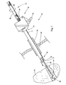
- FIG. 1 depicts preferred surgical cutting instrument 10 positioned through a commercially available, trocar access sheath 55 for morcellating fibroid tumor 15 in body cavity 56 of a patient during a minimally invasive surgical procedure.
- the instrument includes outer sheath 11 and inner elongated member 13.
- the outer sheath includes distal cutting end 12 with circumferential cutting edge 19, proximal end 16 and passage 17 extending longitudinally therebetween for positioning elongated member 13 therethrough.
- Elongated member 13 is sized for insertion through passage 17 and includes distal rod 57 with distal, tissue affixation end 14 that is extendable from the distal cutting end of the outer sheath when the member is positioned in the passage of the sheath.
- distal tissue affixation end comprises helical coil 32.
- the elongated member also includes proximal handle 23 with knurled outer surface 22 and intermediate portion 58.
- Outer sheath 11 and inner elongated member 13 are longitudinally movable with respect to each other via instrument engagement assembly 18, which is depicted with side arm 26 in a disengaged or released position.
- the instrument engagement assembly with side arm 26 in an engaged position urges the outer sheath toward and/or past the distal end of the elongated member as the outer sheath is rotated in a clockwise direction.
- tissue affixed to the distal end of the elongated member is cored as the distal cutting end of the outer sheath engages and cuts the affixed tissue.
- distal end 14 of the elongated member 13 is drawn into passage 17 of the outer sheath for introducing instrument 10 into body cavity 56 of the patient through trocar access sheath 55.
- helical coil 32 is extended from distal cutting end 12 of outer sheath 11 and rotatably advanced into fibroid tumor 15 for stabilizing the position of the tumor with respect to the distal cutting end of the outer sheath.
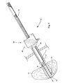
- FIG. 2 depicts a partially sectioned view of surgical cutting instrument 10 with helical coil 32 of the elongated member positioned in fibroid tumor tissue 15 and distal cutting end 12 of outer sheath 11 initially engaging and cutting into the fibroid tumor tissue.
- Side arm 26 of instrument engagement assembly 18 is in the engaged position.
- Outer sheath 11 is being rotated and urged toward helical coil 32 of elongated member 13 so that distal cutting end 12 engages and initially cuts into the fibroid tumor tissue.
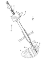
- FIG. 3 depicts a partially sectioned view of surgical cutting instrument 10 further cutting and coring into fibroid tumor tissue 15 with helical coil 32 positioned in and stabilizing the tissue.
- Outer sheath 11 is rotatably advanced toward and/or even past the distal end of helical coil 32 to cut cylindrically shaped plug 33 of fibroid tumor tissue 15 with the helical coil securely positioned therein.
- cutting edge 19 of distal cutting end 12 and the outer sheath are advanced distally, the cylindrically shaped plug of tissue is positioned in passage 17 of the outer sheath.
- Cutting edge 19 of distal cutting end 12 is formed at an angle of approximately 30° with respect to the longitudinal axis of outer sheath 11 to improve the cutting action.
- Cutting edge 19 can also include serrations and be alternatively positioned transverse to the axis of outer sheath 11. Instrument 10 is then pulled proximally and removed from the tissue, leaving tissue passage 34, as depicted in FIG. 4. The helical coil of the elongated member is repositioned for engaging another portion of the fibroid tumor tissue. Decreasing the bulk of a fibroid tumor tissue mass by coring or removing one cylindrically shaped plug of tissue at a time through the small opening of trocar access sheath 55 with, for example, a 5 to 10 mm diameter, allows forthe removal of a relatively large mass of tissue from the body of the patient without a large, traumatic surgical incision.
- FIG. 4 depicts a partially sectioned view of surgical cutting instrument 10 removed from tissue passage 34 and repositioned in fibroid tumortissue 15 for removing another cylindrically shaped tissue plug.
- helical coil 32 is again advanced into tissue 15.
- cylindrically shaped tissue plug 33 contacts tissue 15 for pushing cylindrically shaped tissue plug 33 proximally along distal rod 57 of elongated member 13.
- the outer sheath is rotatably advanced distally toward the helical coil to engage and cut another cylindrically shaped plug of tissue 15. Additional cylindrically shaped tissue plugs are cut and pushed proximally along the elongated member until the outer sheath is filled with tissue plugs.
- the plugs of tissue are conveniently removed from the elongated member after removal from the passage of the outer sheath by first releasing or disengaging instrument engagement assembly 18 of the instrument and removing the elongated member from the passage of the outer sheath while leaving the outer sheath positioned in the body cavity of the patient.
- the cleaned elongated member is replaced in the passage of the outer sheath, and the instrument engagement assembly is placed in the engaged position for removing additional cylindrically shaped plugs of tissue until the tumor tissue is completely morcellated or de- bulked.
- the instrument is removed from the body cavity before releasing or disengaging the instrument engagement assembly of the instrument and removing the elongated member from the passage of the outer sheath.
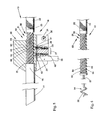
- FIG. 5 depicts a partially sectioned side view of instrument engagement assembly 18 in the engaged position for providing forcible, rotational and longitudinal movement of outer sheath 11 with respect to the inner elongated member 13.
- Engagement assembly 18 includes sheath engagement subassembly 20, which is positioned about proximal end 16 of outer sheath 11, and member engagement subassembly 21, which is positioned along intermediate portion 58 of member 13, for selectively engaging each other.
- Sheath engagement subassembly 20 includes hub 24 with passage 25 extending longitudinally therethrough and communicating with the passage of outer sheath 11 for positioning member engagement subassembly 21 of elongated member 13 therein.
- Sheath engagement subassembly 20 further includes side arm 26 that is pivotedly connected to hub 24, as depicted, with pivot pin 35 for moving between the released and engaged positions.
- Commercially available rubber O-rings 31 are positioned around the pivot pin between the side arm and hub for frictionally maintaining the side arm in a selected position with respect to the hub.
- Side arm 26 of the sheath engagement subassembly includes selector portion 27 with projections 28 and 29 threadably and adjustably positioned in respective apertures 59 and 60 extending laterally through the side arm.
- Projections 28 and 29 extend laterally from side arm 26 and through respective hub apertures 61 and 62 and into respective helical grooves 64 and 65 for engaging respective multiple-start threads 63 and 64 of member engagement subassembly 21 when the side arm is in the depicted engaged position.
- Member engagement subassembly 21 includes positioning apparatus 30 with multiple-start helical threads 63 and 64 and helical grooves 65 and 66 positioned in the outer surface of intermediate portion 58 of elongated member 13. In the released position, side arm 26 of instrument engagement assembly 18 is pulled upward for disengaging projections 28 and 29 from helical threads 63 and 64 and helical grooves 65 and 66. In the released position, the elongated member is easily pulsed proximally from the passage of the outer sheath.
- FIG. 6 depicts a partial view of elongated member 13 with member engagement subassembly 21 positioned along intermediate member portion 58.
- Member engagement subassembly 21 includes positioning apparatus 30 with multiple-start helical threads 63 and 64 and helical grooves 65 and 66 for engaging projections 28 and 29 when the instrument engagement assembly of surgical cutting instrument 10 is in the engaged position. When in the engaged positioned, projections 28 and 29 remain in contact with multiple-start threads 63 and 64.
- Multiple-start threads 63 and 64 include, for example, two or three, and preferably five, starts of external threads. Multiple starts or sets of external threads provide for more forcible, rapid advancement of the elongated member while minimizing muscle fatigue of a surgeon during repeated rotation of the instrument.
- distal rod 57 of inner elongated member 13 comprises, for example, 300 series stainless steel approximately 20.32 cms (8") long with a 0.23 cms (.090") diameter.
- Helical coil 32 of distal, tissue affixation end 14 is approximately 2.22 cms (.875") long with a 0.48 cms (.190") outside diameter.
- Distal rod 57 is soldered, using silver solder and in end cap, to the distal end of member engagement subassembly 21.
- the subassembly comprises a 15.24 cms (6") long, 3/8-16 stainless steel, externally threaded rod having five start, 0.47 percm (1.200 per inch) threads.
- the threaded rod of the member engagement subassembly is buffed to remove sharp points and has a maximum major diameter of approximately 0.91 cms (.360").
- the threaded rod is soldered, using silver solder and an end cap, to proximal handle 23 of the elongated member.
- the handle comprises a stainless steel rod approximately 6.35 cms (2.500") long and 0.95 cms (.375”) in diameter with knurled outer surface 22 for enhancing the grip of the surgeon.
- the solder joints are strengthened by positioning a 0.635 cms (.250”) length of the smaller member in a hole drilled about the center line of the larger member.
- Outer sheath 11 comprises a series 304 stainless steel tube approximately 27.94 cms (11") long with a 1.09 cms (.428") outside diameter and a 0.03 cms (.010") wall thickness.
- the outer sheath tube is fixedly attached to hub 24 of the sheath engagement subassembly 20 by commercially available, medical grade adhesive.
- Hub 24 comprises a clear polycarbonate material approximately 3.81 cms (1.500”) long, 3.18 cms (1.250”) wide, and 1.9 cms (.750”) high.
- the corners at the distal end of the hub have a 45 degree bevel extending proximally longitudinally 0.95 cms (.375").
- a groove approximately 0.97 cms (.380”) wide and 0.95 cms (.375”) deep extends longitudinally approximately 3.17 cms (1.250") for positioning side arm 26 therein.
- a portion of the proximal end of the hub material is removed at a depth of 0.63 cms (.250") for a length of 1.84 cms (.725").
- Passage 25 of the hub has an approximately 1.09 cms (.428") diameter.
- Side arm 26 of the sheath engagement subassembly comprises a clear polycarbonate material approximately 3.81 cms (1.500”) long, 2.22 cms (.875") wide, and 0.95 cms (.375”) deep.
- the arm is formed by removing a 2.86 cms (1.125”) length and 1.27 cms (.500”) wide portion of material and beveling the distal and proximal outside corners of the arm. Apertures 59 and 60 are drilled and threaded through the arm approximately 1.27 cms (.500”) from the pivotal end of the arm and spaced with the center lines of the holes approximately 0.635 cms (.250”) apart using a standard 8-32 drill bit. Pins such as standard 8-32 set screws are threaded and glued into the drilled holes for forming projections 28 and 29.
- the pins have an outside diameter of 0.16 cms (1/1 6") and extend from the arm approximately 0.254 cms (.100") for being positioned in positioning portion 27 of outer sheath engagement subassembly 20.
- hub 24 and side arm 26 are injection molded with integrally formed beveled surfaces, passages, and projections 28 and 29.
- FIGs. 7 and 8 depict another embodiment of the present invention including alternative instrument engagement assembly 46 for instrument 10 including sheath engagement subassembly 68 positioned on outer sheath 11 and memberengagementsubassem- bly 69 positioned on inner elongated member 13.
- the member subassembly includes intermediate positioning portion 47, helical groove 48 and one-start helical external thread 67 formed in the outer surface thereof.
- Sheath engagement subassembly 68 includes selector apparatus 49 with slide arm 50 slidably attached to hub 51.
- Slide arm 50 has slot 52 extending therethrough and communicating with passage 53 of the hub.
- Slot 52 includes a plurality 54 of partial grooves or internal threads positioned along one side thereof for mating with helical groove 48 and thread 67.
- FIG. 9 depicts still another embodiment of the present invention including alternative instrument engagement assembly 36 for instrument 10.
- Instrument engagement assembly 36 includes sheath engagement subassembly 70 positioned on the proximal end of outer sheath 11.
- Subassembly 70 includes hub 37 with inner sleeve 38 proximally extending therefrom.
- Outer sleeve 40 with thumb rest 39 is fixedly positioned longitudinally and rotatably positioned around the outer surface of inner sleeve 38 for the convenience and comfort of the surgeon when pushing the device distally.
- the surgeon's thumb rests on and pushes against the thumb rest to urge the outer sheath distally while the surgeon's fingers gently grip and guide the hub when the pivotedly interconnected side arm is closed against the hub in the engaged position.
- the surgeon's other hand holds the proximal end of the elongated member.
- FIG. 10 depicts yet another embodiment of the present invention including alternative instrument engagement assembly 41 for instrument 10, which includes an enhancement to instrument engagement assembly 36 of FIG.9.
- Instrument engagement assembly 41 includes sheath engagement subassembly 71 positioned on the proximal end of outer sheath 11.
- Subassembly 71 includes hub 73 with reversed side arm 72 and inner sleeve 42 extending proximally therefrom.
- Outer sieeve 43 is fixedly positioned longitudinally and rotatably positioned around inner sleeve 42.
- Outer sleeve 43 includes a laterally extending projection with thumb rest 44 and finger pull 45 positioned distally with respect to thumb rest 44 for enhancing the convenience and comfort of the surgeon when pushing and pulling the hub of the instrument.
- the surgeon's thumb rests on and pushes against the thumb rest while the surgeon's index finger grips and pulls the finger pull.
- the remaining fingers gently grip about the hub when the pivotedly interconnected arm is in the engaged position.
- the surgeon's other hand holds the proximal end of the elongated member.
- instrument engagement assemblies may be devised for providing controlled longitudinal movement of the outer sheath and inner elongated member with respect to each other.
- the positioning of the projections and multiple-start threads can be reversed on the outer sheath and inner elongated member.
- a ratchet type movement can be employed.
- the number of helical grooves or starts of external threads comprising the positioning portion on the elongated member can be varied to change, for example, the force or the distance traveled in one rotation of the outer sheath.
- distal, tissue affixation end of the elongated member can comprise any number of grasping apparatus such as a hook, a spike, a plurality of fingers, or forceps jaws.
- well-known seals can be positioned at the proximal end of the outer sheath to prevent insufflation gas from escaping from the body cavity when the inner member is withdrawn for removing tissue plugs.
Abstract
Description
- This invention relates generally to surgical cutting instrument and particularly to surgical cutting instruments for use in minimally invasive, surgical procedures to morcellate fibroid tumors.
- Undesirable tissue masses such as fibroid tumors are typically dense, tough, and bulky. These characteristics make it difficult to remove a relatively dense tumor using the instruments typically used in minimally invasive endoscopic surgery. Endoscopic tissue graspers and cutters have jaws of limited size and inadequate closing force. Therefore, fibroid tumors are commonly removed by open surgery, with consequent results.
- One approach to endoscopically grasping a tumor is through the use of a myoma drill. This drill comprises a rod with a helically shaped distal end for rotatably advancing into the tumor tissue. When positioned in the tumor tissue, the helical drill is used for only manipulating the tissue. A limitation of the drill is that it is only useful as a manipulator. A separate surgical instrument is necessary for cutting the tumor tissue.
- One approach to endoscopically removing tissue is through the use of a surgical instrument including a hollow inner tube with a crochet-type hook at the distal end thereof. The instrument also includes an outside cutting sleeve with a rotary cutting edge. The rotary cutting edge turns about the axis of the hollow tube to sweep a portion of the crochet-hook face, thereby cutting an object, such as a suture thread or tissue, that is positioned about the hook for removing sutures and biopsy samples. A problem with this instrument is that the outside cutting sleeve can cut only a small object. The instrument cannot cut a relatively large portion of tissue or systematically de- bulk a tissue mass such as a fibroid tumor. Furthermore, the crochet-hook of the instrument cannot grasp or stabilize a tumor or a relatively large portion of tissue.
- Another approach to endoscopically removing tissue is through the use of a biopsy apparatus including an inner cylinder with a distally positioned corkscrew and an outer barrel with a distally positioned pair of cutting jaws for removing tissue masses such as lesions that are too small to be palpable. When the corkscrew is positioned in tissue, the outer barrel is advanced thereover and the jaws are actuated closed for cutting small bites of soft or fatty tissue. A problem with this apparatus is that the cutting jaws close with an inadequate amount of force. As a result, the apparatus cannot cut tough or fibrous tissue. Furthermore, the action of the jaws serves to push tissue distally away from the jaws so that most of the tissue recedes and only a small bite is cut out of the tissue mass. As a result, the apparatus does not penetrate tissue fordebulking a large or dense tumor.
- According to the present invention there is provided a surgical instrument as defined in claim 1.
- The foregoing problems are solved and a technical advance is achieved in an illustrative endoscopic surgical cutting instrument for coring, debulking, and removing large, tough tissue masses such as a fibroid tumor affixed to the distal end thereof. The instrument includes an outer sheath having a distal cutting end and a hollow passage extending longitudinally therethrough. The instrument also includes an inner elongated member with at least part of that member sized for insertion at least partially through the passage of the outer sheath. The inner elongated member has a distal, tissue affixation end that is extendable from the distal cutting end of the outer sheath and positionable in the tissue for advantageously stabilizing the tissue during the surgical coring procedure. The cutting instrument includes an engagement assembly which when in an engaged position is rotatable and urges the outer sheath toward or past the distal end of the inner elongated member. As a result, a large, tough tissue mass affixed to the distal end of the inner elongated member is advantageously cored as the outer sheath is urged toward the distal end of the elongated member and engages the affixed tissue. The cutting instrument is insertable through a trocar access sheath during a minimally invasive surgical procedure for advantageously coring, debulking, and removing a large fibroid tumorthrough the access sheath without the need for a large traumatic incision in the patient. This significantly reduces the patient's length of stay in the hospital and the recovery period associated with the surgery. Scarring is minimized along with the possibility of lesions and adhesions in the internal cavity of the patient.
- The instrument engagement assembly includes a sheath engagement subasssembly positioned on the outer sheath and a member engagement subassembly positioned on the elongated member for selectively engaging each other. The instrument engagement assembly in a disengaged or released position advantageously provides for the insertion and removal of the inner elongated member along with cored tissue.
- The sheath engagement subassembly includes a hub attached about the proximal end of the outer sheath and has a passage communicating with the passage of the outer sheath for inserting the inner elongated member therethrough.
- The member engagement subassembly includes an intermediate portion with multiple start helical threads along the outer surface thereof. The hub of the sheath engagement subassembly includes selector means such as a side arm pivotedly connected to the hub. The side arm has at least one projection extending laterally therefrom and into the passage of the hub for engaging the multiple start helical threads of the inner elongated member when the instrument engagement assembly is in the engaged position. The multiple start helical threads and side arm projections extending therein engage each other to urge the outer sheath toward or past the distal end of the elongated member as the surgeon causes the outer sheath to be rotated around and towards or past the inner member.
- In an another embodiment of the present invention the selector means comprises an arm slidably attached to the proximal end of the hub. The slide arm has a slot positioned therethrough communicating with the passage of the hub. The slot has a plurality of at least partial helical grooves for mating with the helical threads of the elongated member when the instrument engagement assembly is in the engaged position.
- In still another embodiment of the present invention, the hub includes an inner sleeve extending proximally therefrom. An outer sleeve is fixedly positioned longitudinally about the inner sleeve and is rotatable thereabout. The outer sleeve includes a thumb rest positioned on the outer surface of the outer sleeve, thereby providing the physician with additional comfort in rotating the outer sleeve during the surgical coring procedure.
- In yet another embodiment of the present invention, the outer sleeve of the sheath engagement subassembly also includes a finger pull for removing the outer sheath as it rotates about the engaged inner elongated member.
- To advantageously enhance the cutting action of the instrument, the distal cutting end of the outer sheath includes a cutting edge positioned circumferentially thereabout. The distal cutting edge is beveled with respect to the longitudinal axis of the outer sheath to further enhance the cutting action of the instrument.
- The distal, tissue affixation end of the inner elongated member includes a helical coil in the form of a corkscrew for advantageously inserting the inner elongated member into the tough fibroid tumor and stabilizing the tumor during the surgical coring procedure. The anchoring could alternatively be achieved using a plurality of penetrating fixed needles, which could penetrate very tough fibrous tissue and also prevent rotation of the elongated member relative to the outer tube. Anchoring should be achievable in even the toughest of tissues.
-
- FIG. 1 depicts a preferred surgical cutting instrument of the present invention extending into the body cavity of a patient through a surgical access sheath;
- FIG. 2 depicts a partially sectioned view of the instrument of FIG. 1 engaging and cutting into fibroid tumor tissue;
- FIG. 3 depicts a partially sectioned view of the instrument of FIG. 1 coring a plug of the fibroid tumor tissue;
- FIG. 4 depicts a partially sectioned longitudinal view of the instrument of FIG. 1 with the distal, tissue affixation end being repositioned in the fibroid tumor tissue;
- FIG. 5 depicts a partially sectioned view of the instrument engagement assembly of the instrument of FIG. 1 in an engaged position;
- FIG. 6 depicts a partial view of the elongated member of the instrument of FIG. 1;
- FIGs. 7 and 8 depicts another embodiment of the present invention including an alternative instrument engagement assembly for the instrument of FIG.1;
- FIG. 9 depicts still another embodiment of the present invention including a second alternative instrument engagement assembly for the instrument of FIG. 1; and
- FIG. 10 depicts yet another embodiment of the present invention including an enhancement to the instrument engagement assembly for the instrument of FIG. 9.
- FIG. 1 depicts preferred
surgical cutting instrument 10 positioned through a commercially available, trocaraccess sheath 55 for morcellatingfibroid tumor 15 inbody cavity 56 of a patient during a minimally invasive surgical procedure. The instrument includesouter sheath 11 and innerelongated member 13. The outer sheath includesdistal cutting end 12 withcircumferential cutting edge 19,proximal end 16 andpassage 17 extending longitudinally therebetween for positioningelongated member 13 therethrough.Elongated member 13 is sized for insertion throughpassage 17 and includesdistal rod 57 with distal, tissue affixationend 14 that is extendable from the distal cutting end of the outer sheath when the member is positioned in the passage of the sheath. As depicted, distal tissue affixation end compriseshelical coil 32. The elongated member also includesproximal handle 23 with knurledouter surface 22 andintermediate portion 58.Outer sheath 11 and innerelongated member 13 are longitudinally movable with respect to each other viainstrument engagement assembly 18, which is depicted withside arm 26 in a disengaged or released position. The instrument engagement assembly withside arm 26 in an engaged position urges the outer sheath toward and/or past the distal end of the elongated member as the outer sheath is rotated in a clockwise direction. As a result, tissue affixed to the distal end of the elongated member is cored as the distal cutting end of the outer sheath engages and cuts the affixed tissue. - During a minimally invasive surgical procedure,
distal end 14 of theelongated member 13 is drawn intopassage 17 of the outer sheath for introducinginstrument 10 intobody cavity 56 of the patient throughtrocar access sheath 55. When the instrument is positioned in the body cavity,helical coil 32 is extended from distal cuttingend 12 ofouter sheath 11 and rotatably advanced intofibroid tumor 15 for stabilizing the position of the tumor with respect to the distal cutting end of the outer sheath. - FIG. 2 depicts a partially sectioned view of surgical cutting
instrument 10 withhelical coil 32 of the elongated member positioned infibroid tumor tissue 15 and distal cuttingend 12 ofouter sheath 11 initially engaging and cutting into the fibroid tumor tissue.Side arm 26 ofinstrument engagement assembly 18 is in the engaged position.Outer sheath 11 is being rotated and urged towardhelical coil 32 ofelongated member 13 so that distal cuttingend 12 engages and initially cuts into the fibroid tumor tissue. - FIG. 3 depicts a partially sectioned view of surgical cutting
instrument 10 further cutting and coring intofibroid tumor tissue 15 withhelical coil 32 positioned in and stabilizing the tissue.Outer sheath 11 is rotatably advanced toward and/or even past the distal end ofhelical coil 32 to cut cylindrically shapedplug 33 offibroid tumor tissue 15 with the helical coil securely positioned therein. When cuttingedge 19 of distal cuttingend 12 and the outer sheath are advanced distally, the cylindrically shaped plug of tissue is positioned inpassage 17 of the outer sheath. Cuttingedge 19 of distal cuttingend 12 is formed at an angle of approximately 30° with respect to the longitudinal axis ofouter sheath 11 to improve the cutting action. Cuttingedge 19 can also include serrations and be alternatively positioned transverse to the axis ofouter sheath 11.Instrument 10 is then pulled proximally and removed from the tissue, leavingtissue passage 34, as depicted in FIG. 4. The helical coil of the elongated member is repositioned for engaging another portion of the fibroid tumor tissue. Decreasing the bulk of a fibroid tumor tissue mass by coring or removing one cylindrically shaped plug of tissue at a time through the small opening oftrocar access sheath 55 with, for example, a 5 to 10 mm diameter, allows forthe removal of a relatively large mass of tissue from the body of the patient without a large, traumatic surgical incision. - FIG. 4 depicts a partially sectioned view of surgical cutting
instrument 10 removed fromtissue passage 34 and repositioned infibroid tumortissue 15 for removing another cylindrically shaped tissue plug. When so repositioned,helical coil 32 is again advanced intotissue 15. As the helical coil is advanced distally, cylindrically shaped tissue plug 33contacts tissue 15 for pushing cylindrically shaped tissue plug 33 proximally alongdistal rod 57 ofelongated member 13. Then the outer sheath is rotatably advanced distally toward the helical coil to engage and cut another cylindrically shaped plug oftissue 15. Additional cylindrically shaped tissue plugs are cut and pushed proximally along the elongated member until the outer sheath is filled with tissue plugs. The plugs of tissue are conveniently removed from the elongated member after removal from the passage of the outer sheath by first releasing or disengaginginstrument engagement assembly 18 of the instrument and removing the elongated member from the passage of the outer sheath while leaving the outer sheath positioned in the body cavity of the patient. The cleaned elongated member is replaced in the passage of the outer sheath, and the instrument engagement assembly is placed in the engaged position for removing additional cylindrically shaped plugs of tissue until the tumor tissue is completely morcellated or de- bulked. Alternatively, the instrument is removed from the body cavity before releasing or disengaging the instrument engagement assembly of the instrument and removing the elongated member from the passage of the outer sheath. - FIG. 5 depicts a partially sectioned side view of
instrument engagement assembly 18 in the engaged position for providing forcible, rotational and longitudinal movement ofouter sheath 11 with respect to the innerelongated member 13.Engagement assembly 18 includessheath engagement subassembly 20, which is positioned aboutproximal end 16 ofouter sheath 11, andmember engagement subassembly 21, which is positioned alongintermediate portion 58 ofmember 13, for selectively engaging each other.Sheath engagement subassembly 20 includeshub 24 withpassage 25 extending longitudinally therethrough and communicating with the passage ofouter sheath 11 for positioningmember engagement subassembly 21 ofelongated member 13 therein.Sheath engagement subassembly 20 further includesside arm 26 that is pivotedly connected tohub 24, as depicted, withpivot pin 35 for moving between the released and engaged positions. Commercially available rubber O-rings 31 are positioned around the pivot pin between the side arm and hub for frictionally maintaining the side arm in a selected position with respect to the hub.Side arm 26 of the sheath engagement subassembly includesselector portion 27 withprojections respective apertures Projections side arm 26 and throughrespective hub apertures helical grooves start threads member engagement subassembly 21 when the side arm is in the depicted engaged position.Member engagement subassembly 21 includespositioning apparatus 30 with multiple-starthelical threads helical grooves intermediate portion 58 ofelongated member 13. In the released position,side arm 26 ofinstrument engagement assembly 18 is pulled upward for disengagingprojections helical threads helical grooves - FIG. 6 depicts a partial view of
elongated member 13 withmember engagement subassembly 21 positioned alongintermediate member portion 58.Member engagement subassembly 21 includespositioning apparatus 30 with multiple-starthelical threads helical grooves projections instrument 10 is in the engaged position. When in the engaged positioned,projections start threads start threads - As depicted in FIGs 5 and 6,
distal rod 57 of innerelongated member 13 comprises, for example, 300 series stainless steel approximately 20.32 cms (8") long with a 0.23 cms (.090") diameter.Helical coil 32 of distal, tissue affixationend 14 is approximately 2.22 cms (.875") long with a 0.48 cms (.190") outside diameter.Distal rod 57 is soldered, using silver solder and in end cap, to the distal end ofmember engagement subassembly 21. The subassembly comprises a 15.24 cms (6") long, 3/8-16 stainless steel, externally threaded rod having five start, 0.47 percm (1.200 per inch) threads. The threaded rod of the member engagement subassembly is buffed to remove sharp points and has a maximum major diameter of approximately 0.91 cms (.360"). The threaded rod is soldered, using silver solder and an end cap, toproximal handle 23 of the elongated member. The handle comprises a stainless steel rod approximately 6.35 cms (2.500") long and 0.95 cms (.375") in diameter with knurledouter surface 22 for enhancing the grip of the surgeon. The solder joints are strengthened by positioning a 0.635 cms (.250") length of the smaller member in a hole drilled about the center line of the larger member. -
Outer sheath 11 comprises a series 304 stainless steel tube approximately 27.94 cms (11") long with a 1.09 cms (.428") outside diameter and a 0.03 cms (.010") wall thickness. The outer sheath tube is fixedly attached tohub 24 of thesheath engagement subassembly 20 by commercially available, medical grade adhesive.Hub 24 comprises a clear polycarbonate material approximately 3.81 cms (1.500") long, 3.18 cms (1.250") wide, and 1.9 cms (.750") high. The corners at the distal end of the hub have a 45 degree bevel extending proximally longitudinally 0.95 cms (.375"). A groove approximately 0.97 cms (.380") wide and 0.95 cms (.375") deep extends longitudinally approximately 3.17 cms (1.250") for positioningside arm 26 therein. A portion of the proximal end of the hub material is removed at a depth of 0.63 cms (.250") for a length of 1.84 cms (.725").Passage 25 of the hub has an approximately 1.09 cms (.428") diameter.Side arm 26 of the sheath engagement subassembly comprises a clear polycarbonate material approximately 3.81 cms (1.500") long, 2.22 cms (.875") wide, and 0.95 cms (.375") deep. The arm is formed by removing a 2.86 cms (1.125") length and 1.27 cms (.500") wide portion of material and beveling the distal and proximal outside corners of the arm. Apertures 59 and 60 are drilled and threaded through the arm approximately 1.27 cms (.500") from the pivotal end of the arm and spaced with the center lines of the holes approximately 0.635 cms (.250") apart using a standard 8-32 drill bit. Pins such as standard 8-32 set screws are threaded and glued into the drilled holes for formingprojections portion 27 of outersheath engagement subassembly 20. Alternatively,hub 24 andside arm 26 are injection molded with integrally formed beveled surfaces, passages, andprojections - FIGs. 7 and 8 depict another embodiment of the present invention including alternative
instrument engagement assembly 46 forinstrument 10 includingsheath engagement subassembly 68 positioned onouter sheath 11 and memberengagementsubassem-bly 69 positioned on innerelongated member 13. The member subassembly includesintermediate positioning portion 47,helical groove 48 and one-start helicalexternal thread 67 formed in the outer surface thereof.Sheath engagement subassembly 68 includesselector apparatus 49 withslide arm 50 slidably attached tohub 51.Slide arm 50 hasslot 52 extending therethrough and communicating withpassage 53 of the hub.Slot 52 includes aplurality 54 of partial grooves or internal threads positioned along one side thereof for mating withhelical groove 48 andthread 67. Whenslide arm 50 is slid laterally to the engaged position for mating the positioning portion of the elongated member withplurality 54 of partial grooves, the outer sheath and elongated member are rotatably and longitudinally moved with respect to each other in a controlled and forcible manner. - FIG. 9 depicts still another embodiment of the present invention including alternative
instrument engagement assembly 36 forinstrument 10.Instrument engagement assembly 36 includessheath engagement subassembly 70 positioned on the proximal end ofouter sheath 11.Subassembly 70 includeshub 37 withinner sleeve 38 proximally extending therefrom.Outer sleeve 40 withthumb rest 39 is fixedly positioned longitudinally and rotatably positioned around the outer surface ofinner sleeve 38 for the convenience and comfort of the surgeon when pushing the device distally. In use, the surgeon's thumb rests on and pushes against the thumb rest to urge the outer sheath distally while the surgeon's fingers gently grip and guide the hub when the pivotedly interconnected side arm is closed against the hub in the engaged position. The surgeon's other hand holds the proximal end of the elongated member. - FIG. 10 depicts yet another embodiment of the present invention including alternative
instrument engagement assembly 41 forinstrument 10, which includes an enhancement toinstrument engagement assembly 36 of FIG.9.Instrument engagement assembly 41 includessheath engagement subassembly 71 positioned on the proximal end ofouter sheath 11.Subassembly 71 includeshub 73 with reversedside arm 72 andinner sleeve 42 extending proximally therefrom.Outer sieeve 43 is fixedly positioned longitudinally and rotatably positioned aroundinner sleeve 42.Outer sleeve 43 includes a laterally extending projection withthumb rest 44 and finger pull 45 positioned distally with respect tothumb rest 44 for enhancing the convenience and comfort of the surgeon when pushing and pulling the hub of the instrument. In use, the surgeon's thumb rests on and pushes against the thumb rest while the surgeon's index finger grips and pulls the finger pull. The remaining fingers gently grip about the hub when the pivotedly interconnected arm is in the engaged position. The surgeon's other hand holds the proximal end of the elongated member. - It is contemplated that other instrument engagement assemblies may be devised for providing controlled longitudinal movement of the outer sheath and inner elongated member with respect to each other. For example, the positioning of the projections and multiple-start threads can be reversed on the outer sheath and inner elongated member. It is also contemplated that a ratchet type movement can be employed. It is further contemplated that the number of helical grooves or starts of external threads comprising the positioning portion on the elongated member can be varied to change, for example, the force or the distance traveled in one rotation of the outer sheath. It is also further contemplated that the distal, tissue affixation end of the elongated member can comprise any number of grasping apparatus such as a hook, a spike, a plurality of fingers, or forceps jaws. It is still further contemplated that well-known seals can be positioned at the proximal end of the outer sheath to prevent insufflation gas from escaping from the body cavity when the inner member is withdrawn for removing tissue plugs.
Claims (14)
Applications Claiming Priority (2)
| Application Number | Priority Date | Filing Date | Title |
|---|---|---|---|
| US97384792A | 1992-11-09 | 1992-11-09 | |
| US973847 | 1992-11-09 |
Publications (2)
| Publication Number | Publication Date |
|---|---|
| EP0601709A2 true EP0601709A2 (en) | 1994-06-15 |
| EP0601709A3 EP0601709A3 (en) | 1994-10-12 |
Family
ID=25521288
Family Applications (1)
| Application Number | Title | Priority Date | Filing Date |
|---|---|---|---|
| EP19930308826 Withdrawn EP0601709A3 (en) | 1992-11-09 | 1993-11-04 | Surgical cutting instrument for coring tissue affixed thereto. |
Country Status (5)
| Country | Link |
|---|---|
| US (1) | US5488958A (en) |
| EP (1) | EP0601709A3 (en) |
| JP (1) | JPH06197904A (en) |
| AU (1) | AU5050593A (en) |
| CA (1) | CA2102084A1 (en) |
Cited By (17)
| Publication number | Priority date | Publication date | Assignee | Title |
|---|---|---|---|---|
| EP0712609A1 (en) * | 1994-11-18 | 1996-05-22 | Mohsin Al-Tameem | Device for excision of a fistula and method for using same |
| ES2116914A1 (en) * | 1996-05-14 | 1998-07-16 | Palazon Hernandez Jesus Maria | Device for the resection of perianal fistulas |
| WO2000012009A3 (en) * | 1998-09-01 | 2000-06-29 | Senorx Inc | Securing surgical instruments at target tissue sites |
| US6659105B2 (en) | 1998-02-26 | 2003-12-09 | Senorx, Inc. | Tissue specimen isolating and damaging device and method |
| US6716179B2 (en) | 1998-03-03 | 2004-04-06 | Senorx, Inc. | Sentinel node location and biopsy |
| US7189206B2 (en) | 2003-02-24 | 2007-03-13 | Senorx, Inc. | Biopsy device with inner cutter |
| WO2008029088A1 (en) * | 2006-09-07 | 2008-03-13 | Cyrus Medical Limited | Tissue morcellating device |
| US7651467B2 (en) | 1998-04-08 | 2010-01-26 | Senorx, Inc | Dilation devices and methods for removing tissue specimens |
| US7896877B2 (en) | 2004-05-20 | 2011-03-01 | Gyrus Medical Limited | Surgical instrument |
| US7981051B2 (en) | 2005-08-05 | 2011-07-19 | Senorx, Inc. | Biopsy device with fluid delivery to tissue specimens |
| US8137346B2 (en) | 1998-09-01 | 2012-03-20 | Senorx, Inc. | Electrosurgical lesion location device |
| EP2453808A1 (en) * | 2009-07-13 | 2012-05-23 | C.R. Bard Inc. | Instrument for applying a surgical fastener |
| WO2012106293A1 (en) * | 2011-01-31 | 2012-08-09 | Boston Scientific Scimed, Inc. | Distal tip configurations for biopsy with eus fna |
| US8915864B2 (en) | 2005-08-05 | 2014-12-23 | Senorx, Inc. | Biopsy device with fluid delivery to tissue specimens |
| US9750487B2 (en) | 2005-05-23 | 2017-09-05 | Senorx, Inc. | Tissue cutting member for a biopsy device |
| US10105125B2 (en) | 2004-12-16 | 2018-10-23 | Senorx, Inc. | Biopsy device with aperture orientation and improved tip |
| US11589849B2 (en) | 2003-02-24 | 2023-02-28 | Senorx, Inc. | Biopsy device with selectable tissue receiving aperature orientation and site illumination |
Families Citing this family (210)
| Publication number | Priority date | Publication date | Assignee | Title |
|---|---|---|---|---|
| US6106538A (en) * | 1984-05-14 | 2000-08-22 | Shiber; Samuel | Method for forming an internal coronary bypass |
| US20030216761A1 (en) * | 1990-03-27 | 2003-11-20 | Samuel Shiber | Guidewire system |
| US5857982A (en) * | 1995-09-08 | 1999-01-12 | United States Surgical Corporation | Apparatus and method for removing tissue |
| US5817034A (en) | 1995-09-08 | 1998-10-06 | United States Surgical Corporation | Apparatus and method for removing tissue |
| US5782775A (en) * | 1995-10-20 | 1998-07-21 | United States Surgical Corporation | Apparatus and method for localizing and removing tissue |
| CA2187975C (en) * | 1995-10-20 | 2001-05-01 | Lisa W. Heaton | Surgical apparatus and method for marking tissue location |
| US5800445A (en) * | 1995-10-20 | 1998-09-01 | United States Surgical Corporation | Tissue tagging device |
| US5709697A (en) * | 1995-11-22 | 1998-01-20 | United States Surgical Corporation | Apparatus and method for removing tissue |
| EP0959775B1 (en) * | 1996-03-25 | 2003-09-17 | Safe Conduct AB | Device for extraction of tissue or the like |
| US5713921A (en) * | 1996-03-29 | 1998-02-03 | Bonutti; Peter M. | Suture anchor |
| US5980545A (en) * | 1996-05-13 | 1999-11-09 | United States Surgical Corporation | Coring device and method |
| US6468228B1 (en) | 1996-06-18 | 2002-10-22 | Vance Products Incorporated | Surgical tissue morcellator |
| US20020019642A1 (en) * | 1996-07-23 | 2002-02-14 | Keith Milliman | Anastomosis instrument and method for performing same |
| US5718717A (en) | 1996-08-19 | 1998-02-17 | Bonutti; Peter M. | Suture anchor |
| US5882316A (en) | 1996-08-29 | 1999-03-16 | City Of Hope | Minimally invasive biopsy device |
| WO1998011814A2 (en) * | 1996-09-20 | 1998-03-26 | United States Surgical Corporation | Coil fastener applier and remover |
| US5830221A (en) * | 1996-09-20 | 1998-11-03 | United States Surgical Corporation | Coil fastener applier |
| US6120520A (en) | 1997-05-27 | 2000-09-19 | Angiotrax, Inc. | Apparatus and methods for stimulating revascularization and/or tissue growth |
| US5931848A (en) * | 1996-12-02 | 1999-08-03 | Angiotrax, Inc. | Methods for transluminally performing surgery |
| US5899915A (en) * | 1996-12-02 | 1999-05-04 | Angiotrax, Inc. | Apparatus and method for intraoperatively performing surgery |
| US6102926A (en) * | 1996-12-02 | 2000-08-15 | Angiotrax, Inc. | Apparatus for percutaneously performing myocardial revascularization having means for sensing tissue parameters and methods of use |
| US6165188A (en) * | 1996-12-02 | 2000-12-26 | Angiotrax, Inc. | Apparatus for percutaneously performing myocardial revascularization having controlled cutting depth and methods of use |
| US6051008A (en) | 1996-12-02 | 2000-04-18 | Angiotrax, Inc. | Apparatus having stabilization members for percutaneously performing surgery and methods of use |
| US6010476A (en) * | 1996-12-02 | 2000-01-04 | Angiotrax, Inc. | Apparatus for performing transmyocardial revascularization |
| US5947989A (en) * | 1996-12-12 | 1999-09-07 | United States Surgical Corporation | Method and apparatus for transmyocardial revascularization |
| US5827316A (en) * | 1997-06-05 | 1998-10-27 | Atrion Medical Products, Inc. | Rotating aortic punch |
| US7037316B2 (en) * | 1997-07-24 | 2006-05-02 | Mcguckin Jr James F | Rotational thrombectomy device |
| US6080113A (en) | 1998-09-11 | 2000-06-27 | Imagyn Medical Technologies California, Inc. | Incisional breast biopsy device |
| US6383145B1 (en) | 1997-09-12 | 2002-05-07 | Imagyn Medical Technologies California, Inc. | Incisional breast biopsy device |
| US6551253B2 (en) | 1997-09-12 | 2003-04-22 | Imagyn Medical Technologies | Incisional breast biopsy device |
| US5972012A (en) * | 1997-10-17 | 1999-10-26 | Angiotrax, Inc. | Cutting apparatus having articulable tip |
| US6139557A (en) * | 1997-11-07 | 2000-10-31 | Prolifix Medical, Inc. | Apparatus for making wire with radial expansible guide section and methods of manufacturing the same |
| US20040010206A1 (en) * | 1998-02-10 | 2004-01-15 | Dubrul William R. | Intraoperative tissue treatment methods |
| US6280441B1 (en) | 1997-12-15 | 2001-08-28 | Sherwood Services Ag | Apparatus and method for RF lesioning |
| US6007495A (en) * | 1998-01-22 | 1999-12-28 | United States Surgical Corporation | Biopsy apparatus and method |
| US6416527B1 (en) * | 1998-01-28 | 2002-07-09 | St. Jude Medical Cardiovascular Group, Inc. | Vessel cutting device |
| US6045551A (en) | 1998-02-06 | 2000-04-04 | Bonutti; Peter M. | Bone suture |
| US20020144696A1 (en) * | 1998-02-13 | 2002-10-10 | A. Adam Sharkawy | Conduits for use in placing a target vessel in fluid communication with a source of blood |
| US6651670B2 (en) * | 1998-02-13 | 2003-11-25 | Ventrica, Inc. | Delivering a conduit into a heart wall to place a coronary vessel in communication with a heart chamber and removing tissue from the vessel or heart wall to facilitate such communication |
| US7027398B2 (en) * | 2001-04-12 | 2006-04-11 | General Instrument Corporation | Method and apparatus for monitoring voice conversations from customer premises equipment |
| CA2320956A1 (en) * | 1998-02-13 | 1999-08-19 | Ventrica, Inc. | Methods and devices providing transmyocardial blood flow to the arterial vascular system of the heart |
| US6540695B1 (en) | 1998-04-08 | 2003-04-01 | Senorx, Inc. | Biopsy anchor device with cutter |
| US5954671A (en) * | 1998-04-20 | 1999-09-21 | O'neill; Michael J. | Bone harvesting method and apparatus |
| US7063711B1 (en) | 1998-05-29 | 2006-06-20 | By-Pass, Inc. | Vascular surgery |
| US6979338B1 (en) | 1998-05-29 | 2005-12-27 | By-Pass Inc. | Low profile anastomosis connector |
| US7396359B1 (en) * | 1998-05-29 | 2008-07-08 | Bypass, Inc. | Vascular port device |
| WO1999062415A1 (en) | 1998-05-29 | 1999-12-09 | By-Pass, Inc. | Methods and devices for vascular surgery |
| US6945980B2 (en) | 1998-06-03 | 2005-09-20 | Medtronic, Inc. | Multiple loop tissue connector apparatus and methods |
| US6641593B1 (en) | 1998-06-03 | 2003-11-04 | Coalescent Surgical, Inc. | Tissue connector apparatus and methods |
| US6607541B1 (en) * | 1998-06-03 | 2003-08-19 | Coalescent Surgical, Inc. | Tissue connector apparatus and methods |
| US6613059B2 (en) | 1999-03-01 | 2003-09-02 | Coalescent Surgical, Inc. | Tissue connector apparatus and methods |
| US6224603B1 (en) * | 1998-06-09 | 2001-05-01 | Nuvasive, Inc. | Transiliac approach to entering a patient's intervertebral space |
| US6086543A (en) * | 1998-06-24 | 2000-07-11 | Rubicor Medical, Inc. | Fine needle and core biopsy devices and methods |
| US6679851B2 (en) | 1998-09-01 | 2004-01-20 | Senorx, Inc. | Tissue accessing and anchoring device and method |
| US6083237A (en) * | 1998-10-23 | 2000-07-04 | Ethico Endo-Surgery, Inc. | Biopsy instrument with tissue penetrating spiral |
| US6080176A (en) * | 1998-10-30 | 2000-06-27 | Atrion Medical Products, Inc. | Medical punch with high shear angle cutting edges |
| US6508252B1 (en) | 1998-11-06 | 2003-01-21 | St. Jude Medical Atg, Inc. | Medical grafting methods and apparatus |
| AU760879B2 (en) | 1998-11-25 | 2003-05-22 | United States Surgical Corporation | Biopsy system |
| US6254601B1 (en) * | 1998-12-08 | 2001-07-03 | Hysterx, Inc. | Methods for occlusion of the uterine arteries |
| US7578828B2 (en) * | 1999-01-15 | 2009-08-25 | Medtronic, Inc. | Methods and devices for placing a conduit in fluid communication with a target vessel |
| US6519319B1 (en) | 1999-02-19 | 2003-02-11 | Nuvasive, Inc. | Image intensifier reticle system |
| US8118822B2 (en) * | 1999-03-01 | 2012-02-21 | Medtronic, Inc. | Bridge clip tissue connector apparatus and methods |
| US6695859B1 (en) | 1999-04-05 | 2004-02-24 | Coalescent Surgical, Inc. | Apparatus and methods for anastomosis |
| US6699256B1 (en) * | 1999-06-04 | 2004-03-02 | St. Jude Medical Atg, Inc. | Medical grafting apparatus and methods |
| US6306132B1 (en) * | 1999-06-17 | 2001-10-23 | Vivant Medical | Modular biopsy and microwave ablation needle delivery apparatus adapted to in situ assembly and method of use |
| US6267759B1 (en) | 1999-06-22 | 2001-07-31 | Senorx, Inc. | Shaped scalpel |
| US6368343B1 (en) * | 2000-03-13 | 2002-04-09 | Peter M. Bonutti | Method of using ultrasonic vibration to secure body tissue |
| US6447516B1 (en) | 1999-08-09 | 2002-09-10 | Peter M. Bonutti | Method of securing tissue |
| US8529583B1 (en) | 1999-09-03 | 2013-09-10 | Medtronic, Inc. | Surgical clip removal apparatus |
| US20080018016A1 (en) * | 1999-09-10 | 2008-01-24 | Rapacki Alan R | Manufacturing conduits for use in placing a target vessel in fluid communication with a source of blood |
| US6635214B2 (en) * | 1999-09-10 | 2003-10-21 | Ventrica, Inc. | Manufacturing conduits for use in placing a target vessel in fluid communication with a source of blood |
| US8414543B2 (en) | 1999-10-22 | 2013-04-09 | Rex Medical, L.P. | Rotational thrombectomy wire with blocking device |
| AU2614901A (en) | 1999-10-22 | 2001-04-30 | Boston Scientific Corporation | Double balloon thrombectomy catheter |
| US6926730B1 (en) * | 2000-10-10 | 2005-08-09 | Medtronic, Inc. | Minimally invasive valve repair procedure and apparatus |
| US6635073B2 (en) | 2000-05-03 | 2003-10-21 | Peter M. Bonutti | Method of securing body tissue |
| US6564806B1 (en) | 2000-02-18 | 2003-05-20 | Thomas J. Fogarty | Device for accurately marking tissue |
| WO2001060235A2 (en) * | 2000-02-18 | 2001-08-23 | Fogarty Thomas J M D | Improved device for accurately marking tissue |
| US6722371B1 (en) | 2000-02-18 | 2004-04-20 | Thomas J. Fogarty | Device for accurately marking tissue |
| US9138222B2 (en) | 2000-03-13 | 2015-09-22 | P Tech, Llc | Method and device for securing body tissue |
| US7094251B2 (en) | 2002-08-27 | 2006-08-22 | Marctec, Llc. | Apparatus and method for securing a suture |
| CA2403289A1 (en) * | 2000-03-20 | 2001-09-27 | By-Pass, Inc. | Graft and connector delivery |
| US6551332B1 (en) * | 2000-03-31 | 2003-04-22 | Coalescent Surgical, Inc. | Multiple bias surgical fastener |
| US6550482B1 (en) * | 2000-04-21 | 2003-04-22 | Vascular Control Systems, Inc. | Methods for non-permanent occlusion of a uterine artery |
| US20030120306A1 (en) * | 2000-04-21 | 2003-06-26 | Vascular Control System | Method and apparatus for the detection and occlusion of blood vessels |
| US7223279B2 (en) | 2000-04-21 | 2007-05-29 | Vascular Control Systems, Inc. | Methods for minimally-invasive, non-permanent occlusion of a uterine artery |
| US6450973B1 (en) * | 2000-06-16 | 2002-09-17 | Kieran P. J. Murphy | Biopsy gun |
| AU2001273421A1 (en) * | 2000-07-13 | 2002-01-30 | Bioheart, Inc. | Deployment system for myocardial cellular material |
| US6635065B2 (en) * | 2000-11-16 | 2003-10-21 | Vascular Control Systems, Inc. | Doppler directed suture ligation device and method |
| US6638286B1 (en) | 2000-11-16 | 2003-10-28 | Vascular Control Systems, Inc. | Doppler directed suture ligation device and method |
| BE1013974A3 (en) * | 2001-02-16 | 2003-01-14 | Janssens Jacques Phillibert | Device for taking a tissue language. |
| CA2442362C (en) * | 2001-03-28 | 2009-08-11 | Vascular Control Systems, Inc. | Method and apparatus for the detection and ligation of uterine arteries |
| US20030120286A1 (en) * | 2001-03-28 | 2003-06-26 | Vascular Control System | Luminal clip applicator with sensor |
| US7354444B2 (en) * | 2001-03-28 | 2008-04-08 | Vascular Control Systems, Inc. | Occlusion device with deployable paddles for detection and occlusion of blood vessels |
| US20060293701A1 (en) * | 2001-05-02 | 2006-12-28 | Medtronic, Inc. | Self-closing surgical clip for tissue |
| WO2003001980A2 (en) * | 2001-06-29 | 2003-01-09 | Medquest Products,Inc. | Cannulation apparatus and method |
| US8292908B2 (en) * | 2001-06-29 | 2012-10-23 | World Heart Corporation | Endoscopic cannulation apparatus and method |
| US6776787B2 (en) | 2001-10-05 | 2004-08-17 | Trinh D. Phung | Surgical punch device |
| US7241302B2 (en) * | 2001-10-18 | 2007-07-10 | Tyco Healthcare Group Lp | Anastomosis instrument and method for performing same |
| US6878147B2 (en) | 2001-11-02 | 2005-04-12 | Vivant Medical, Inc. | High-strength microwave antenna assemblies |
| US6719765B2 (en) | 2001-12-03 | 2004-04-13 | Bonutti 2003 Trust-A | Magnetic suturing system and method |
| US6814743B2 (en) * | 2001-12-26 | 2004-11-09 | Origin Medsystems, Inc. | Temporary seal and method for facilitating anastomosis |
| US7029482B1 (en) * | 2002-01-22 | 2006-04-18 | Cardica, Inc. | Integrated anastomosis system |
| US7335216B2 (en) * | 2002-01-22 | 2008-02-26 | Cardica, Inc. | Tool for creating an opening in tissue |
| US8012164B1 (en) | 2002-01-22 | 2011-09-06 | Cardica, Inc. | Method and apparatus for creating an opening in the wall of a tubular vessel |
| US7223274B2 (en) * | 2002-01-23 | 2007-05-29 | Cardica, Inc. | Method of performing anastomosis |
| US9155544B2 (en) | 2002-03-20 | 2015-10-13 | P Tech, Llc | Robotic systems and methods |
| US7207996B2 (en) * | 2002-04-04 | 2007-04-24 | Vascular Control Systems, Inc. | Doppler directed suturing and compression device and method |
| US6926725B2 (en) * | 2002-04-04 | 2005-08-09 | Rex Medical, L.P. | Thrombectomy device with multi-layered rotational wire |
| US7197363B2 (en) | 2002-04-16 | 2007-03-27 | Vivant Medical, Inc. | Microwave antenna having a curved configuration |
| US6752767B2 (en) * | 2002-04-16 | 2004-06-22 | Vivant Medical, Inc. | Localization element with energized tip |
| ES2360938T3 (en) * | 2002-04-17 | 2011-06-10 | Tyco Healthcare Group Lp | SEWING TOOL. |
| US20030199974A1 (en) * | 2002-04-18 | 2003-10-23 | Coalescent Surgical, Inc. | Annuloplasty apparatus and methods |
| US7229452B2 (en) * | 2002-04-22 | 2007-06-12 | Tyco Healthcare Group Lp | Tack and tack applier |
| US7195142B2 (en) * | 2003-05-30 | 2007-03-27 | Tyco Healthcare Group Lp | End-to-end anastomosis instrument and method for performing same |
| US6769594B2 (en) * | 2002-05-31 | 2004-08-03 | Tyco Healthcare Group, Lp | End-to-end anastomosis instrument and method for performing same |
| WO2003101308A1 (en) | 2002-06-04 | 2003-12-11 | Office Of Technology Licensing Stanford University | Device and method for rapid aspiration and collection of body tissue from within an enclosed body space |
| US20070276352A1 (en) * | 2002-06-04 | 2007-11-29 | Stemcor Systems, Inc. | Removable device and method for tissue disruption |
| US7155273B2 (en) * | 2002-07-29 | 2006-12-26 | Taylor Geoffrey L | Blanching response pressure sore detector apparatus and method |
| US8066724B2 (en) | 2002-09-12 | 2011-11-29 | Medtronic, Inc. | Anastomosis apparatus and methods |
| US20060025788A1 (en) * | 2002-09-25 | 2006-02-02 | By-Pass, Inc. | Anastomotic leg arrangement |
| US8105345B2 (en) * | 2002-10-04 | 2012-01-31 | Medtronic, Inc. | Anastomosis apparatus and methods |
| US7172603B2 (en) * | 2002-11-19 | 2007-02-06 | Vascular Control Systems, Inc. | Deployable constrictor for uterine artery occlusion |
| US20040097961A1 (en) * | 2002-11-19 | 2004-05-20 | Vascular Control System | Tenaculum for use with occlusion devices |
| US7404821B2 (en) * | 2003-01-30 | 2008-07-29 | Vascular Control Systems, Inc. | Treatment for post partum hemorrhage |
| US7651511B2 (en) * | 2003-02-05 | 2010-01-26 | Vascular Control Systems, Inc. | Vascular clamp for caesarian section |
| US7333844B2 (en) | 2003-03-28 | 2008-02-19 | Vascular Control Systems, Inc. | Uterine tissue monitoring device and method |
| US20050075659A1 (en) * | 2003-03-30 | 2005-04-07 | Fidel Realyvasquez | Apparatus and methods for minimally invasive valve surgery |
| US20040202694A1 (en) * | 2003-04-11 | 2004-10-14 | Vascular Control Systems, Inc. | Embolic occlusion of uterine arteries |
| US7497864B2 (en) | 2003-04-30 | 2009-03-03 | Marctec, Llc. | Tissue fastener and methods for using same |
| JP4015582B2 (en) * | 2003-05-09 | 2007-11-28 | ニスカ株式会社 | Image forming apparatus |
| US7322999B2 (en) * | 2003-05-09 | 2008-01-29 | Atrion Medical Products, Inc. | Tissue punch and method for creating an anastomosis for locating a bypass graft |
| US20050143768A1 (en) * | 2003-06-17 | 2005-06-30 | Samuel Shiber | Sleeved guidewire system method of use |
| US7104966B2 (en) | 2003-07-16 | 2006-09-12 | Samuel Shiber | Guidewire system with exposed midsection |
| US20050177073A1 (en) * | 2003-06-17 | 2005-08-11 | Samuel Shiber | Guidewire system with a deflectable distal tip |
| US8308708B2 (en) * | 2003-07-15 | 2012-11-13 | Abbott Cardiovascular Systems Inc. | Deployment system for myocardial cellular material |
| US7311703B2 (en) * | 2003-07-18 | 2007-12-25 | Vivant Medical, Inc. | Devices and methods for cooling microwave antennas |
| US7182769B2 (en) * | 2003-07-25 | 2007-02-27 | Medtronic, Inc. | Sealing clip, delivery systems, and methods |
| US20050043749A1 (en) | 2003-08-22 | 2005-02-24 | Coalescent Surgical, Inc. | Eversion apparatus and methods |
| US8394114B2 (en) * | 2003-09-26 | 2013-03-12 | Medtronic, Inc. | Surgical connection apparatus and methods |
| US7325546B2 (en) * | 2003-11-20 | 2008-02-05 | Vascular Control Systems, Inc. | Uterine artery occlusion device with cervical receptacle |
| US7686817B2 (en) * | 2003-11-25 | 2010-03-30 | Vascular Control Systems, Inc. | Occlusion device for asymmetrical uterine artery anatomy |
| US7879047B2 (en) | 2003-12-10 | 2011-02-01 | Medtronic, Inc. | Surgical connection apparatus and methods |
| US9408592B2 (en) | 2003-12-23 | 2016-08-09 | Senorx, Inc. | Biopsy device with aperture orientation and improved tip |
| US20080039873A1 (en) | 2004-03-09 | 2008-02-14 | Marctec, Llc. | Method and device for securing body tissue |
| DE102004021713A1 (en) * | 2004-04-30 | 2005-11-17 | Karl Storz Gmbh & Co. Kg | Arrangement of medical instruments for surgical purposes |
| US20050251063A1 (en) * | 2004-05-07 | 2005-11-10 | Raghuveer Basude | Safety device for sampling tissue |
| US9271766B2 (en) | 2004-10-26 | 2016-03-01 | P Tech, Llc | Devices and methods for stabilizing tissue and implants |
| US9173647B2 (en) | 2004-10-26 | 2015-11-03 | P Tech, Llc | Tissue fixation system |
| US9463012B2 (en) | 2004-10-26 | 2016-10-11 | P Tech, Llc | Apparatus for guiding and positioning an implant |
| US20060089646A1 (en) | 2004-10-26 | 2006-04-27 | Bonutti Peter M | Devices and methods for stabilizing tissue and implants |
| US7875036B2 (en) * | 2004-10-27 | 2011-01-25 | Vascular Control Systems, Inc. | Short term treatment for uterine disorder |
| US20090204021A1 (en) * | 2004-12-16 | 2009-08-13 | Senorx, Inc. | Apparatus and method for accessing a body site |
| US9089323B2 (en) | 2005-02-22 | 2015-07-28 | P Tech, Llc | Device and method for securing body tissue |
| US20070049973A1 (en) * | 2005-08-29 | 2007-03-01 | Vascular Control Systems, Inc. | Method and device for treating adenomyosis and endometriosis |
| JP2007135751A (en) * | 2005-11-16 | 2007-06-07 | Gc Corp | Dental implant |
| US10368899B2 (en) * | 2006-01-13 | 2019-08-06 | Heartware, Inc. | Surgical tool for coring precise holes and providing for retrieval of tissue |
| US7967820B2 (en) | 2006-02-07 | 2011-06-28 | P Tech, Llc. | Methods and devices for trauma welding |
| US11253296B2 (en) | 2006-02-07 | 2022-02-22 | P Tech, Llc | Methods and devices for intracorporeal bonding of implants with thermal energy |
| US11278331B2 (en) | 2006-02-07 | 2022-03-22 | P Tech Llc | Method and devices for intracorporeal bonding of implants with thermal energy |
| US8496657B2 (en) | 2006-02-07 | 2013-07-30 | P Tech, Llc. | Methods for utilizing vibratory energy to weld, stake and/or remove implants |
| US11246638B2 (en) | 2006-05-03 | 2022-02-15 | P Tech, Llc | Methods and devices for utilizing bondable materials |
| US7568753B2 (en) * | 2006-06-15 | 2009-08-04 | Mattel, Inc. | Children's ride-on vehicles with reconfigured bodies and methods for forming the same |
| DE102006039696A1 (en) * | 2006-08-21 | 2008-02-28 | Hamou, Jacques, Dr. | Apparatus for resection and / or ablation of organic tissue by means of high frequency current and resectoscope |
| US8068921B2 (en) | 2006-09-29 | 2011-11-29 | Vivant Medical, Inc. | Microwave antenna assembly and method of using the same |
| US20080103412A1 (en) | 2006-11-01 | 2008-05-01 | Yem Chin | Removing Tissue |
| US10413284B2 (en) | 2006-11-07 | 2019-09-17 | Corvia Medical, Inc. | Atrial pressure regulation with control, sensing, monitoring and therapy delivery |
| US10624621B2 (en) | 2006-11-07 | 2020-04-21 | Corvia Medical, Inc. | Devices and methods for the treatment of heart failure |
| US20110257723A1 (en) | 2006-11-07 | 2011-10-20 | Dc Devices, Inc. | Devices and methods for coronary sinus pressure relief |
| US9028520B2 (en) * | 2006-12-22 | 2015-05-12 | The Spectranetics Corporation | Tissue separating systems and methods |
| EP2120732A2 (en) * | 2007-01-05 | 2009-11-25 | Medtronic, Inc. | Anastomosis systems and methods |
| DE102007004808A1 (en) * | 2007-01-31 | 2008-08-07 | Kaltenbach & Voigt Gmbh | Dental treatment instrument with coupling device for transmission of movement and detachable attachment of a treatment tool |
| US8617185B2 (en) | 2007-02-13 | 2013-12-31 | P Tech, Llc. | Fixation device |
| US20110060357A1 (en) * | 2007-02-22 | 2011-03-10 | WISAP Gesellschaft fuer wissenschaftlichen Apparat ebau mbH | Device for cutting out and removing cylinders of tissue from a tissue and the use thereof |
| US7846123B2 (en) * | 2007-04-24 | 2010-12-07 | Emory University | Conduit device and system for implanting a conduit device in a tissue wall |
| EP2578166B1 (en) * | 2007-06-08 | 2014-09-17 | St. Jude Medical, Inc. | Devices for transcatheter prosthetic heart valve implantation and access closure |
| US8915958B2 (en) | 2007-06-08 | 2014-12-23 | St. Jude Medical, Inc. | Devices for transcatheter prosthetic heart valve implantation and access closure |
| US8128647B2 (en) * | 2007-11-14 | 2012-03-06 | Kennedy John S | Surgical instrument for detecting, isolating and excising tumors |
| US20090125035A1 (en) * | 2007-11-14 | 2009-05-14 | Kennedy John S | Surgical Cutting Instrument for Breast Surgery |
| US8292880B2 (en) * | 2007-11-27 | 2012-10-23 | Vivant Medical, Inc. | Targeted cooling of deployable microwave antenna |
| US8177836B2 (en) * | 2008-03-10 | 2012-05-15 | Medtronic, Inc. | Apparatus and methods for minimally invasive valve repair |
| US8449478B2 (en) | 2008-05-16 | 2013-05-28 | Conquest Medical Technologies | Biopsy device |
| US9566146B2 (en) * | 2008-12-19 | 2017-02-14 | St. Jude Medical, Inc. | Cardiovascular valve and valve housing apparatuses and systems |
| US20100160939A1 (en) * | 2008-12-19 | 2010-06-24 | St. Jude Medical, Inc. | Systems, apparatuses, and methods for cardiovascular cutting devices and valves |
| EP2400899A4 (en) | 2009-02-24 | 2015-03-18 | P Tech Llc | Methods and devices for utilizing bondable materials |
| US8518060B2 (en) | 2009-04-09 | 2013-08-27 | Medtronic, Inc. | Medical clip with radial tines, system and method of using same |
| US8668704B2 (en) | 2009-04-24 | 2014-03-11 | Medtronic, Inc. | Medical clip with tines, system and method of using same |
| WO2011006067A1 (en) | 2009-07-09 | 2011-01-13 | Ams Research Corporation | Apparatus and methods of treatment of pathologic proliferative conditions uterine tissue |
| EP2528646A4 (en) | 2010-01-29 | 2017-06-28 | DC Devices, Inc. | Devices and systems for treating heart failure |
| WO2012068315A1 (en) | 2010-11-21 | 2012-05-24 | Robert Peliks | Tissue removal device and method of use |
| EP2673038B1 (en) | 2011-02-10 | 2017-07-19 | Corvia Medical, Inc. | Apparatus to create and maintain an intra-atrial pressure relief opening |
| US9226734B2 (en) | 2011-03-24 | 2016-01-05 | Cook Medical Technologies Llc | Closed side-sampling biopsy device |
| WO2013096965A1 (en) | 2011-12-22 | 2013-06-27 | Dc Devices, Inc. | Methods and devices for intra-atrial devices having selectable flow rates |
| BE1020378A3 (en) * | 2012-02-01 | 2013-08-06 | Jacques Philibert Janssens | INSTRUMENT FOR TAKING A TISSUE STEEL. |
| US9347533B2 (en) | 2012-07-25 | 2016-05-24 | Cook Medical Technologies Llc | Rotational drive system for a biopsy member |
| EP2922458B1 (en) | 2012-11-26 | 2017-04-05 | Koninklijke Philips N.V. | Spiral biopsy device |
| US9301735B2 (en) | 2012-12-19 | 2016-04-05 | Cook Medical Technologies Llc | Drive system for a biopsy member |
| US10076377B2 (en) | 2013-01-05 | 2018-09-18 | P Tech, Llc | Fixation systems and methods |
| NL2010089C2 (en) * | 2013-01-08 | 2014-07-09 | Univ Delft Tech | Morcellator. |
| US9320502B2 (en) | 2013-03-12 | 2016-04-26 | Cook Medical Technologies Llc | Cytology balloon |
| US9039637B2 (en) | 2013-03-13 | 2015-05-26 | Cook Medical Technologies Llc | Flexible cytology coil |
| US9119609B2 (en) | 2013-03-13 | 2015-09-01 | Cook Medical Technologies Llc | Rotating cell collection device |
| US9095330B2 (en) | 2013-03-13 | 2015-08-04 | Cook Medical Technologies Llc | Perforated tube for cell collection |
| WO2015030652A1 (en) * | 2013-08-26 | 2015-03-05 | Elos Medtech Timmersdala Ab | Dental drill system |
| US10016255B2 (en) * | 2013-08-26 | 2018-07-10 | Elos Medtech Timmersdala Ab | Dental surgery device |
| US10675450B2 (en) | 2014-03-12 | 2020-06-09 | Corvia Medical, Inc. | Devices and methods for treating heart failure |
| JP6799526B2 (en) | 2014-07-23 | 2020-12-16 | コルヴィア メディカル インコーポレイテッド | Equipment and methods for the treatment of heart failure |
| US10058393B2 (en) | 2015-10-21 | 2018-08-28 | P Tech, Llc | Systems and methods for navigation and visualization |
| US11389141B2 (en) | 2016-02-01 | 2022-07-19 | RegenMed Systems, Inc. | Cannula for tissue disruption |
| JP7300570B2 (en) * | 2018-02-13 | 2023-06-30 | 国立大学法人 長崎大学 | resection instrument |
| US11571232B2 (en) | 2020-04-17 | 2023-02-07 | Covidien Lp | Corkscrew tissue resecting device |
Citations (1)
| Publication number | Priority date | Publication date | Assignee | Title |
|---|---|---|---|---|
| WO1992012676A2 (en) * | 1991-01-25 | 1992-08-06 | Wisap Gesellschaft für wissenschaftlichen Apparatebau mbH | Cervical biopsy punch |
Family Cites Families (7)
| Publication number | Priority date | Publication date | Assignee | Title |
|---|---|---|---|---|
| US1888347A (en) * | 1931-08-05 | 1932-11-22 | Clipper Belt Lacer Company | Punch |
| US2850007A (en) * | 1956-05-31 | 1958-09-02 | American Cyanamid Co | Biopsy device |
| US4010737A (en) * | 1971-06-14 | 1977-03-08 | Vilaghy Miklos I | Bone biopsy instrument kit |
| US3995619A (en) * | 1975-10-14 | 1976-12-07 | Glatzer Stephen G | Combination subcutaneous suture remover, biopsy sampler and syringe |
| US4010543A (en) * | 1975-10-28 | 1977-03-08 | Nusbaum Max J | Hole cutting apparatus |
| US4682606A (en) * | 1986-02-03 | 1987-07-28 | Decaprio Vincent H | Localizing biopsy apparatus |
| US5018530A (en) * | 1989-06-15 | 1991-05-28 | Research Corporation Technologies, Inc. | Helical-tipped lesion localization needle device and method of using the same |
-
1993
- 1993-10-29 CA CA002102084A patent/CA2102084A1/en not_active Abandoned
- 1993-11-04 EP EP19930308826 patent/EP0601709A3/en not_active Withdrawn
- 1993-11-05 AU AU50505/93A patent/AU5050593A/en not_active Abandoned
- 1993-11-09 JP JP5302202A patent/JPH06197904A/en active Pending
-
1994
- 1994-11-07 US US08/335,221 patent/US5488958A/en not_active Expired - Lifetime
Patent Citations (1)
| Publication number | Priority date | Publication date | Assignee | Title |
|---|---|---|---|---|
| WO1992012676A2 (en) * | 1991-01-25 | 1992-08-06 | Wisap Gesellschaft für wissenschaftlichen Apparatebau mbH | Cervical biopsy punch |
Cited By (38)
| Publication number | Priority date | Publication date | Assignee | Title |
|---|---|---|---|---|
| US5628762A (en) * | 1994-11-18 | 1997-05-13 | Al-Tameem; Moshin | Method of using a device for excision of a fistula |
| US5643305A (en) * | 1994-11-18 | 1997-07-01 | Al-Tameem; Moshin | Device for excision of a fistula |
| EP0712609A1 (en) * | 1994-11-18 | 1996-05-22 | Mohsin Al-Tameem | Device for excision of a fistula and method for using same |
| ES2116914A1 (en) * | 1996-05-14 | 1998-07-16 | Palazon Hernandez Jesus Maria | Device for the resection of perianal fistulas |
| US6659105B2 (en) | 1998-02-26 | 2003-12-09 | Senorx, Inc. | Tissue specimen isolating and damaging device and method |
| US7264596B2 (en) | 1998-03-03 | 2007-09-04 | Senorx, Inc. | Methods and apparatus for securing medical instruments to desired locations in a patient's body |
| US6540693B2 (en) | 1998-03-03 | 2003-04-01 | Senorx, Inc. | Methods and apparatus for securing medical instruments to desired locations in a patients body |
| US6716179B2 (en) | 1998-03-03 | 2004-04-06 | Senorx, Inc. | Sentinel node location and biopsy |
| US6958044B2 (en) | 1998-03-03 | 2005-10-25 | Senorx, Inc. | Methods and apparatus for securing medical instruments to desired locations in a patient's body |
| US6676658B2 (en) | 1998-04-08 | 2004-01-13 | Senorx, Inc. | Tissue specimen isolating and damaging device and method |
| US7651467B2 (en) | 1998-04-08 | 2010-01-26 | Senorx, Inc | Dilation devices and methods for removing tissue specimens |
| US8229553B2 (en) | 1998-09-01 | 2012-07-24 | Senorx, Inc. | Methods and apparatus for securing medical instruments to desired locations in a patient's body |
| WO2000012009A3 (en) * | 1998-09-01 | 2000-06-29 | Senorx Inc | Securing surgical instruments at target tissue sites |
| US9216012B2 (en) | 1998-09-01 | 2015-12-22 | Senorx, Inc | Methods and apparatus for securing medical instruments to desired locations in a patient's body |
| US8137346B2 (en) | 1998-09-01 | 2012-03-20 | Senorx, Inc. | Electrosurgical lesion location device |
| US9510809B2 (en) | 1999-01-27 | 2016-12-06 | Senorx, Inc. | Tissue specimen isolating and damaging device and method |
| US8636734B2 (en) | 1999-01-27 | 2014-01-28 | Senorx, Inc. | Tissue specimen isolating and damaging device and method |
| US9044215B2 (en) | 2003-02-24 | 2015-06-02 | Senorx, Inc. | Biopsy device with selectable tissue receiving aperature orientation and site illumination |
| US10172595B2 (en) | 2003-02-24 | 2019-01-08 | Senorx, Inc. | Biopsy device with selectable tissue receiving aperture orientation and site illumination |
| US11589849B2 (en) | 2003-02-24 | 2023-02-28 | Senorx, Inc. | Biopsy device with selectable tissue receiving aperature orientation and site illumination |
| US8460204B2 (en) | 2003-02-24 | 2013-06-11 | Senorx, Inc. | Biopsy device with inner cutting member |
| US11534147B2 (en) | 2003-02-24 | 2022-12-27 | Senorx, Inc. | Biopsy device with a removable sample recieving cartridge |
| US10335127B2 (en) | 2003-02-24 | 2019-07-02 | Senorx, Inc. | Biopsy device with selectable tissue receiving aperature orientation and site illumination |
| US7189206B2 (en) | 2003-02-24 | 2007-03-13 | Senorx, Inc. | Biopsy device with inner cutter |
| US10231715B2 (en) | 2003-02-24 | 2019-03-19 | Senorx, Inc. | Biopsy device with inner cutting member |
| US7896877B2 (en) | 2004-05-20 | 2011-03-01 | Gyrus Medical Limited | Surgical instrument |
| US10105125B2 (en) | 2004-12-16 | 2018-10-23 | Senorx, Inc. | Biopsy device with aperture orientation and improved tip |
| US11426149B2 (en) | 2005-05-23 | 2022-08-30 | SenoRx., Inc. | Tissue cutting member for a biopsy device |
| US10478161B2 (en) | 2005-05-23 | 2019-11-19 | Senorx, Inc. | Tissue cutting member for a biopsy device |
| US9750487B2 (en) | 2005-05-23 | 2017-09-05 | Senorx, Inc. | Tissue cutting member for a biopsy device |
| US8915864B2 (en) | 2005-08-05 | 2014-12-23 | Senorx, Inc. | Biopsy device with fluid delivery to tissue specimens |
| US10064609B2 (en) | 2005-08-05 | 2018-09-04 | Senorx, Inc. | Method of collecting one or more tissue specimens |
| US10874381B2 (en) | 2005-08-05 | 2020-12-29 | Senorx, Inc. | Biopsy device with fluid delivery to tissue specimens |
| US7981051B2 (en) | 2005-08-05 | 2011-07-19 | Senorx, Inc. | Biopsy device with fluid delivery to tissue specimens |
| WO2008029088A1 (en) * | 2006-09-07 | 2008-03-13 | Cyrus Medical Limited | Tissue morcellating device |
| EP2453808A1 (en) * | 2009-07-13 | 2012-05-23 | C.R. Bard Inc. | Instrument for applying a surgical fastener |
| EP2453808A4 (en) * | 2009-07-13 | 2014-09-03 | Bard Inc C R | Instrument for applying a surgical fastener |
| WO2012106293A1 (en) * | 2011-01-31 | 2012-08-09 | Boston Scientific Scimed, Inc. | Distal tip configurations for biopsy with eus fna |
Also Published As
| Publication number | Publication date |
|---|---|
| JPH06197904A (en) | 1994-07-19 |
| AU5050593A (en) | 1994-05-19 |
| CA2102084A1 (en) | 1994-05-10 |
| EP0601709A3 (en) | 1994-10-12 |
| US5488958A (en) | 1996-02-06 |
Similar Documents
| Publication | Publication Date | Title |
|---|---|---|
| US5488958A (en) | Surgical cutting instrument for coring tissue affixed thereto | |
| US6468228B1 (en) | Surgical tissue morcellator | |
| US5591187A (en) | Laparoscopic tissue retrieval device and method | |
| US6875183B2 (en) | Biopsy needle | |
| US5163942A (en) | Surgical instrument with grasping loop for laparoscopic procedures | |
| US5954734A (en) | Insertable suture passing grasping probe and methodology for using same | |
| CA2569878C (en) | Surgical closure instrument and methods | |
| US3995619A (en) | Combination subcutaneous suture remover, biopsy sampler and syringe | |
| US5290303A (en) | Surgical cutting instrument | |
| US5383886A (en) | Methods and instruments for performing medical procedures percutaneously without a trocar | |
| US5947983A (en) | Tissue cutting and stitching device and method | |
| US5507758A (en) | Insertable suture grasping probe guide, and methodology for using same | |
| US6159224A (en) | Multiple needle suturing instrument and method | |
| US5797927A (en) | Combined tissue clamping and suturing instrument | |
| US5591180A (en) | Surgical suturing apparatus | |
| US5376096A (en) | Medical instrument for driving a suture needle | |
| US5795308A (en) | Apparatus for coaxial breast biopsy | |
| US5474565A (en) | Endoscopic suturing needle | |
| EP0720442B1 (en) | Multiple biopsy sampling coring device | |
| US5922002A (en) | Surgical instrument with jaws and movable internal biopsy device and method for use thereof | |
| US5899919A (en) | Miniature endoscopic surgical instrument assembly and method of use | |
| US20080243163A1 (en) | Perforating Trocar | |
| US20040087978A1 (en) | Surgical fascia closure instrument, guide and method | |
| US5746760A (en) | Semi-automatic tissue morcellation device | |
| CA2271621A1 (en) | Graduated bone graft harvester |
Legal Events
| Date | Code | Title | Description |
|---|---|---|---|
| PUAI | Public reference made under article 153(3) epc to a published international application that has entered the european phase |
Free format text: ORIGINAL CODE: 0009012 |
|
| AK | Designated contracting states |
Kind code of ref document: A2 Designated state(s): AT BE CH DE DK ES FR GB GR IE IT LI LU MC NL PT SE |
|
| PUAL | Search report despatched |
Free format text: ORIGINAL CODE: 0009013 |
|
| AK | Designated contracting states |
Kind code of ref document: A3 Designated state(s): AT BE CH DE DK ES FR GB GR IE IT LI LU MC NL PT SE |
|
| 17P | Request for examination filed |
Effective date: 19950309 |
|
| STAA | Information on the status of an ep patent application or granted ep patent |
Free format text: STATUS: THE APPLICATION HAS BEEN WITHDRAWN |
|
| 18W | Application withdrawn |
Withdrawal date: 19950717 |