EP0601857A1 - Method of marking an ophthalmic lens - Google Patents
Method of marking an ophthalmic lens Download PDFInfo
- Publication number
- EP0601857A1 EP0601857A1 EP93309910A EP93309910A EP0601857A1 EP 0601857 A1 EP0601857 A1 EP 0601857A1 EP 93309910 A EP93309910 A EP 93309910A EP 93309910 A EP93309910 A EP 93309910A EP 0601857 A1 EP0601857 A1 EP 0601857A1
- Authority
- EP
- European Patent Office
- Prior art keywords
- mark
- marking
- laser beam
- mask
- laser
- Prior art date
- Legal status (The legal status is an assumption and is not a legal conclusion. Google has not performed a legal analysis and makes no representation as to the accuracy of the status listed.)
- Granted
Links
- 238000000034 method Methods 0.000 title claims abstract description 62
- 230000005855 radiation Effects 0.000 claims abstract description 12
- 238000004519 manufacturing process Methods 0.000 abstract 1
- CURLTUGMZLYLDI-UHFFFAOYSA-N Carbon dioxide Chemical compound O=C=O CURLTUGMZLYLDI-UHFFFAOYSA-N 0.000 description 24
- 238000001000 micrograph Methods 0.000 description 20
- 229910002092 carbon dioxide Inorganic materials 0.000 description 12
- 230000008569 process Effects 0.000 description 8
- 230000000694 effects Effects 0.000 description 6
- 230000015572 biosynthetic process Effects 0.000 description 5
- 239000000463 material Substances 0.000 description 5
- 239000005337 ground glass Substances 0.000 description 4
- 230000002093 peripheral effect Effects 0.000 description 4
- 230000002925 chemical effect Effects 0.000 description 3
- 150000002632 lipids Chemical class 0.000 description 3
- 102000004169 proteins and genes Human genes 0.000 description 3
- 108090000623 proteins and genes Proteins 0.000 description 3
- 230000002730 additional effect Effects 0.000 description 2
- 238000004090 dissolution Methods 0.000 description 2
- 238000005530 etching Methods 0.000 description 2
- 238000010330 laser marking Methods 0.000 description 2
- 239000007788 liquid Substances 0.000 description 2
- 238000003754 machining Methods 0.000 description 2
- 230000003287 optical effect Effects 0.000 description 2
- 230000009467 reduction Effects 0.000 description 2
- BESKSSIEODQWBP-UHFFFAOYSA-N 3-tris(trimethylsilyloxy)silylpropyl 2-methylprop-2-enoate Chemical compound CC(=C)C(=O)OCCC[Si](O[Si](C)(C)C)(O[Si](C)(C)C)O[Si](C)(C)C BESKSSIEODQWBP-UHFFFAOYSA-N 0.000 description 1
- 230000002411 adverse Effects 0.000 description 1
- 230000008901 benefit Effects 0.000 description 1
- 239000001569 carbon dioxide Substances 0.000 description 1
- 230000008859 change Effects 0.000 description 1
- 238000010276 construction Methods 0.000 description 1
- 238000007796 conventional method Methods 0.000 description 1
- 230000000873 masking effect Effects 0.000 description 1
- 238000005259 measurement Methods 0.000 description 1
- 230000007246 mechanism Effects 0.000 description 1
- 239000000126 substance Substances 0.000 description 1
- 230000003746 surface roughness Effects 0.000 description 1
Images


Classifications
-
- B—PERFORMING OPERATIONS; TRANSPORTING
- B41—PRINTING; LINING MACHINES; TYPEWRITERS; STAMPS
- B41M—PRINTING, DUPLICATING, MARKING, OR COPYING PROCESSES; COLOUR PRINTING
- B41M5/00—Duplicating or marking methods; Sheet materials for use therein
- B41M5/26—Thermography ; Marking by high energetic means, e.g. laser otherwise than by burning, and characterised by the material used
- B41M5/262—Thermography ; Marking by high energetic means, e.g. laser otherwise than by burning, and characterised by the material used recording or marking of inorganic surfaces or materials, e.g. glass, metal, or ceramics
-
- B—PERFORMING OPERATIONS; TRANSPORTING
- B23—MACHINE TOOLS; METAL-WORKING NOT OTHERWISE PROVIDED FOR
- B23K—SOLDERING OR UNSOLDERING; WELDING; CLADDING OR PLATING BY SOLDERING OR WELDING; CUTTING BY APPLYING HEAT LOCALLY, e.g. FLAME CUTTING; WORKING BY LASER BEAM
- B23K26/00—Working by laser beam, e.g. welding, cutting or boring
- B23K26/02—Positioning or observing the workpiece, e.g. with respect to the point of impact; Aligning, aiming or focusing the laser beam
- B23K26/06—Shaping the laser beam, e.g. by masks or multi-focusing
- B23K26/064—Shaping the laser beam, e.g. by masks or multi-focusing by means of optical elements, e.g. lenses, mirrors or prisms
- B23K26/066—Shaping the laser beam, e.g. by masks or multi-focusing by means of optical elements, e.g. lenses, mirrors or prisms by using masks
-
- B—PERFORMING OPERATIONS; TRANSPORTING
- B29—WORKING OF PLASTICS; WORKING OF SUBSTANCES IN A PLASTIC STATE IN GENERAL
- B29C—SHAPING OR JOINING OF PLASTICS; SHAPING OF MATERIAL IN A PLASTIC STATE, NOT OTHERWISE PROVIDED FOR; AFTER-TREATMENT OF THE SHAPED PRODUCTS, e.g. REPAIRING
- B29C59/00—Surface shaping of articles, e.g. embossing; Apparatus therefor
- B29C59/16—Surface shaping of articles, e.g. embossing; Apparatus therefor by wave energy or particle radiation, e.g. infrared heating
-
- G—PHYSICS
- G02—OPTICS
- G02B—OPTICAL ELEMENTS, SYSTEMS OR APPARATUS
- G02B1/00—Optical elements characterised by the material of which they are made; Optical coatings for optical elements
- G02B1/04—Optical elements characterised by the material of which they are made; Optical coatings for optical elements made of organic materials, e.g. plastics
- G02B1/041—Lenses
- G02B1/043—Contact lenses
-
- G—PHYSICS
- G02—OPTICS
- G02C—SPECTACLES; SUNGLASSES OR GOGGLES INSOFAR AS THEY HAVE THE SAME FEATURES AS SPECTACLES; CONTACT LENSES
- G02C7/00—Optical parts
- G02C7/02—Lenses; Lens systems ; Methods of designing lenses
- G02C7/021—Lenses; Lens systems ; Methods of designing lenses with pattern for identification or with cosmetic or therapeutic effects
-
- B—PERFORMING OPERATIONS; TRANSPORTING
- B29—WORKING OF PLASTICS; WORKING OF SUBSTANCES IN A PLASTIC STATE IN GENERAL
- B29C—SHAPING OR JOINING OF PLASTICS; SHAPING OF MATERIAL IN A PLASTIC STATE, NOT OTHERWISE PROVIDED FOR; AFTER-TREATMENT OF THE SHAPED PRODUCTS, e.g. REPAIRING
- B29C35/00—Heating, cooling or curing, e.g. crosslinking or vulcanising; Apparatus therefor
- B29C35/02—Heating or curing, e.g. crosslinking or vulcanizing during moulding, e.g. in a mould
- B29C35/08—Heating or curing, e.g. crosslinking or vulcanizing during moulding, e.g. in a mould by wave energy or particle radiation
- B29C35/0805—Heating or curing, e.g. crosslinking or vulcanizing during moulding, e.g. in a mould by wave energy or particle radiation using electromagnetic radiation
- B29C2035/0827—Heating or curing, e.g. crosslinking or vulcanizing during moulding, e.g. in a mould by wave energy or particle radiation using electromagnetic radiation using UV radiation
-
- B—PERFORMING OPERATIONS; TRANSPORTING
- B29—WORKING OF PLASTICS; WORKING OF SUBSTANCES IN A PLASTIC STATE IN GENERAL
- B29C—SHAPING OR JOINING OF PLASTICS; SHAPING OF MATERIAL IN A PLASTIC STATE, NOT OTHERWISE PROVIDED FOR; AFTER-TREATMENT OF THE SHAPED PRODUCTS, e.g. REPAIRING
- B29C35/00—Heating, cooling or curing, e.g. crosslinking or vulcanising; Apparatus therefor
- B29C35/02—Heating or curing, e.g. crosslinking or vulcanizing during moulding, e.g. in a mould
- B29C35/08—Heating or curing, e.g. crosslinking or vulcanizing during moulding, e.g. in a mould by wave energy or particle radiation
- B29C35/0805—Heating or curing, e.g. crosslinking or vulcanizing during moulding, e.g. in a mould by wave energy or particle radiation using electromagnetic radiation
- B29C2035/0838—Heating or curing, e.g. crosslinking or vulcanizing during moulding, e.g. in a mould by wave energy or particle radiation using electromagnetic radiation using laser
Definitions
- the present invention relates to a method of marking an ophthalmic lens such as a contact lens and an intraocular lens with a letter, a symbol or the like.
- a mark including a letter, a symbol or the like is put on the peripheral edge of the ophthalmic lens.
- marking has been performed, for example, by a machining method in which a tool having a small cutting edge is used to scratch the surface of the ophthalmic lens so as to inscribe a mark, and an etching method in which a chemical is used to etch a mark.
- This marking method using a laser beam is advantageously much easier to control, has a better reproducibility and can mark a number of lenses in a shorter time than the machining method and the etching method described above.
- Such a marking method by a laser beam is exemplified by a method of marking a soft contact lens disclosed in Japanese Patent Publication No. 62-37368.
- CO2 laser carbon dioxide laser
- the wavelength (10600 nm) emitted by the CO2 laser belongs to the infrared region and involves a quite large thermal energy.
- the CO2 laser beam is converged by a converging lens system into a minute beam spot at the surface of the lens, and the beam spot is moved along the pattern of the mark.
- the thermal energy causes the lens material to be dissolved so as to form recesses which define a mark including a letter, a symbol or the like.
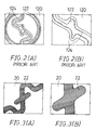
- FIGS. 2(A) and 2(B) An example of a mark obtained by the marking method using the CO2 laser is shown in FIGS. 2(A) and 2(B).
- FIGS. 2(A) and 2(B) schematically illustrate a microphotograph of the mark obtained by the CO2 laser.
- FIG. 2(A) is a schematic view of the microphotograph of a low magnification
- FIG. 2(B) is a schematic view of the microphotograph of a high magnification.
- a mark or recesses 122 are formed on a portion of the surface 120 of the contact lens by the thermal effect of the CO2 laser. According to the marking method using the CO2 laser, the thermal energy of the laser beam is so strong that the recesses 122 thus formed are deeper than required.
- the recesses 122 shown in FIGS. 2(A) and 2(B) have a depth of 10 ⁇ m or more.
- these deep recesses 122 tend to develop deposits such as lipid and protein therein, which may possibly impart an adverse effect to the eye when the lens is put in the eye. Furthermore, the mechanical strength of the contact lens at the recessed portions 122 is reduced, causing easy breakage of the contact lens.
- the recesses 122 are surrounded by peripheral ridges 124, as shown in FIGS. 2(A) and 2(B).
- the method involves the disadvantages that the mark appears rather obscure and that the ridges 124 give an unpleasant feeling when the lens is put in the eye.
- Such a marking method is disclosed, for example, in Japanese Laid-Open Patent Publications Nos. 64-13520 and No. 61-193119.
- an object of the present invention to provide a method of marking an ophthalmic lens in which a very distinguishable and clear mark having a minimum depth as required can be positively and easily inscribed on the ophthalmic lens.
- a method of marking a surface of an ophthalmic lens by radiation of a laser beam through masks wherein the laser beam has a wavelength in the ultraviolet region and the masks are composed of a mark pattern forming mask and a mesh-like mask.
- the mark pattern forming mask has a perforated portion provided in the form of the mark, and the mesh-like mask has a number of minute holes formed over the whole surface thereof.
- the laser beam used for marking is emitted from an excimer laser in which KrF is used as a laser medium and has a wavelength in the ultraviolet region.
- the method of marking an ophthalmic lens according to the first aspect of the invention is effective to positively and readily inscribe a very distinguishable and clear mark having a minimum depth as required.
- the method of marking an ophthalmic lens according to the second aspect uses a laser beam having a wavelength in the ultraviolet region. It also employs the combination of a mark pattern forming mask having a perforated portion provided in the form of the mark and a mesh-like mask having a number of minute holes formed over the whole surface thereof. The ultraviolet light which has passed through these two masks is radiated on the surface of the ophthalmic lens.
- the mark thus obtained is an assembly of a number of minute cavities arranged in the form of the mark pattern. Consequently, the physically pitted mark is inscribed on the lens surface, the mark being composed of optically minute irregularities. As the laser beam having a wavelength in the ultraviolet region is used, the mark thus formed has a quite small depth.
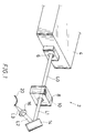
- FIG. 1 is a perspective view showing the arrangement of main parts of a marking apparatus used to perform the first embodiment.
- a marking apparatus 2 for an ophthalmic lens used to perform this embodiment is mainly composed of an excimer laser source 4 which emits an ultraviolet laser beam LO, a mask 10 for forming a mark pattern, a mask holder 8, a reflector 14 and a converging lens 16.
- the ultraviolet laser beam LO emitted from a laser outlet 6 of the excimer laser source 4 impinges on the mask 10 held in the mask holder 8 to form a laser beam L1 having a mark pattern.
- the reflector 14 is used to change the direction of the laser beam L1, which is then converged by the converging lens 16 into a minute spot to be radiated on a contact lens 20.
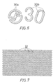
- FIG. 6 is a plan view of patterns used in the first embodiment of the ophthalmic lens marking method.
- a mark to be inscribed on the ophthalmic lens may have symbol, number or letter patterns including a logotype of the manufacturer, a lens parameter, a lot number, an identification symbol indicating the front or back side of a soft contact lens, a symbol indicating the right or left eye use.
- This embodiment uses a mask 10 having a symbol pattern 30a and a letter pattern 30b as shown in FIG. 6. These patterns 30a and 30b are composed of perforations formed through the mask 10 shown in FIG. 1. When the ultraviolet laser beam L0 impinges on the mask 10, only the portions of the laser beam corresponding to the patterns 30a and 30b pass through the mask 10, forming the laser beam L1 having the mark pattern.
- the mask 10 having the patterns 30a and 30b is set in the mask holder 8, and the contact lens 20 is placed on a support base not shown. Then, the excimer laser source 4 is activated to emit an ultraviolet laser beam L0 from the laser outlet 6. The ultraviolet laser beam L0 impinges on the mask 10 to form the laser beam L1 having the mark pattern.
- the laser beam L1 in turn impinges on the reflector 14 to produce a laser beam L2 directed vertically to the surface of the contact lens 20.
- the laser beam L2 is then converged by the converging lens 16 into a minute spot, constituting a laser beam L3 which is then radiated on the marking position of the contact lens 20.
- the marking process was carried out under four conditions which were respectively defined in Table 1.
- Two types of lenses a water-absorbable soft contact lens (hereinafter abbreviated to "SCL”) and an oxygen-permeable hard contact lens (hereinafter abbreviated to “HCL”) were used for marking.
- SCL water-absorbable soft contact lens
- HCL oxygen-permeable hard contact lens
- the SCL contained N-vinylpyrolidone as a main component.
- the HCL contained tris (trimethylsiloxy) silyl propylmethacrylate and methylmetacrylate as main components. Marking of the SCL was carried out in a dry condition.
- KrF was used as a laser medium for the excimer laser source 4.
- the excimer laser using KrF as a laser medium emitted a laser beam having a wavelength of 248 nm.
- the pulse energy density of the excimer laser 4 was fixed between 700 and 900 mJ/cm2.
- the result obtained by the prior art CO2 laser (emitting a laser beam having a wavelength of 10600 nm) is shown in the rightmost column in Table 1.
- the depth of the mark obtained by the marking method of this embodiment is much smaller than that by the prior art CO2 laser. This can eliminate deposits such as lipid and protein on the mark and the problem of increased possibility of breakage of the contact lens due to reduction of the mechanical strength.
- FIGS. 3(A) and 3(B) schematically illustrate a microphotograph of a symbol portion of the mark inscribed on the contact lens by the marking method of this embodiment.
- FIG. 3 (A) schematically shows the microphotograph of a low magnification
- FIG. 3(B) schematically shows the microphotograph of a high magnification.
- the pattern of the mask used in this embodiment is the same as that used in the prior art masking in FIGS. 2(A) and 2(B) and slightly different from the symbol pattern 30a in FIG. 6.
- the mark 22 inscribed on the surface of the contact lens (SCL) 20 is not accompanied with such peripheral ridges 124 surrounding the mark 122 as shown in FIGS. 2(A) and 2(B). This is because the ultraviolet laser beam emitted by the excimer laser 4 imparts little thermal effect to the contact lens 20.
- the mark 22 is opaque like ground glass, which is distinguishable from the surrounding portion thereof. This is caused by the chemical effect given by the ultraviolet laser beam emitted by the excimer laser 4 using KrF as a laser medium.
- KrF KrF as a laser medium.
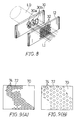
- FIGS. 4(A) and 4(B) schematically illustrates a microphotograph of a mark inscribed on an ophthalmic lens by the marking method of the second embodiment.
- This embodiment also employs the excimer laser in which KrF is used as a laser medium to mark a contact lens (SCL) but under the condition a little different from that in the first embodiment.
- the mark of this embodiment has a surface of a minute embossed pattern which is a little different from that shown in FIGS. 3(A) and 3(B).
- the mark becomes optically opaque like ground glass, forming a readily distinguishable mark having a minimum depth as required.
- the mark As shown in FIGS. 5(A) and 5(B), with the ArF excimer laser, the mark has a smooth surface with little irregularities, showing a remarkable difference from those in FIGS. 3(A), 3(B), 4(A) and 4(B). Thus, the mark in FIGS. 5(A) and 5(B) looks rather transparent and is difficult to be distinguished.
- FIGS. 6 and 7 are respective plan views of two masks used in the method of the third embodiment.
- a mask including symbol and letter patterns 30a and 30b as shown in FIG. 6 and another mask having a plurality of circular holes 32 regularly arranged in vertical and transverse lines as shown in FIG. 7 are used.
- FIG. 8 is a perspective view of the masks used in the method of the third embodiment.
- a first mask 10 including the symbol and letter patterns 30a and 30b shown in FIG. 6 and a second mask 12 having the plurality of regularly arranged circular holes 32 shown in FIG. 7 are placed one after the other. These two masks 10 and 12 are set one after the other in the mask holder 8. Any number of masks may be used as required, or a single mask including the symbol and letter patterns 30a and 30b as well as the plurality of circular holes 32 may be used.
- the mesh size of the mesh-like mask 12, i.e. outer diameter of the circular hole 32 is set so that the mesh size of the mark inscribed on the contact lens may range from 1 ⁇ m to 0.5 mm, preferably from 5 ⁇ m to 0.1 mm.
- various mesh-like masks of respective mesh sizes which are easy to be prepared may be used, and reduced or enlarged through a laser optical system so as to obtain a mesh pattern having a mesh size within a desired range.
- the ultraviolet laser beam L0 emitted from the excimer laser source 4 in FIG. 1 sequentially passes through the first mask 10 and the second mask 12 to form a patterned ultraviolet laser beam L11, which is then converged and radiated on a contact lens similarly to the first and second embodiments.
- condition of the marking process of this embodiment is similar to condition 3 shown in Table 1 except the masks described above.
- the depth of the mark obtained in this embodiment was measured similarly to the first embodiment and found to be very small, ranging from 1.0 to 1.5 ⁇ m, in spite of two shots of beam radiation.
- FIGS. 9(A) and 9(B) schematically illustrate a microphotograph of a portion of the symbol pattern 30a of the mark inscribed on the contact lens by the marking method of this embodiment, in which FIG. 9(A) shows the microphotograph of a low magnification, while FIG. 9(B) shows the microphotograph of a high magnification.
- the mark 72 inscribed on the surface of a contact lens (SCL) 70 is composed of an assembly of small circular patterns 74. This is because the laser beam passes through the symbol and letter mask patterns 30a and 30b and then through the pattern composed of the plurality of circular holes 32 to form the patterned laser beam L11 which is radiated on the contact lens.
- the mark 72 is free from formation of such peripheral ridges 124 as shown in FIGS. 2(A) and 2(B).
- the mark 72 is formed of the assembly of small circular patterns 74, light is irregularly reflected in the mark 72, causing the mark to be very clear and distinguishable, in spite of the rather small mark depth ranging from 1.0 to 1.5 ⁇ m. Furthermore, the mark 72 composed of the assembly of small circular patterns 74 is advantageously clearly distinguishable, even when the surface of the ophthalmic lens is covered with liquid.
- FIG. 10 illustrates a pattern of a mesh-like mask used in the fourth embodiment
- FIG. 11 schematically illustrates a microphotograph of a mark obtained by the marking method of this embodiment.
- the mesh-like mask 12 in FIG. 8 is replaced by a mesh-like mask more densely perforated as shown in FIG. 10, while a mark pattern forming mask similar to the mask 10 shown in FIG. 8 is used.
- the marking condition is the same as condition 3 shown in Table 1.
- the mark thus obtained is composed of an assembly of minute concave and convex patterns in the form of the mark, which gives an opaque appearance like ground glass.
- the mark thus obtained is very distinguishable.
- three kinds of mark pattern forming masks as shown in FIGS. 12(A), 12(B) and 12(C) are used for laser marking.
- the mesh-like mask used in this embodiment is the one shown in FIG. 10, and the marking condition is similar to condition 3 shown in Table 1.
- FIGS. 13(A), 13(B) and 13(C) schematically show microphotographs of the respective marks obtained.
- various masks having different mark patterns perforated can be used in combination with the mesh-like mask to obtain various marks which are physically pitted, providing opaque appearance corresponding to the respective mark patterns.
- KrF is used as a laser medium for the excimer laser
- other laser media for the excimer laser can be used to obtain the similar effect.
- Such laser media other than KrF may include KrCl, ArF, ArCl, XeBr or the like.
- excimer laser source is used for the ultraviolet laser source in the above embodiments, other ultraviolet laser sources may be used.
- the mesh-like mask used in the above third to fifth embodiments has circular holes, it will be understood that the shape of the hole may be other than circular.
- a lattice mesh square or rectangular holes
- oval or triangular holes may be used.
- the mesh size (the diameter of a hole and the space between holes) of the mark inscribed on the contact lens is set to range from 1 ⁇ m to 0.5 mm, preferably from 5 ⁇ m to 0.1 mm.
- the ophthalmic lenses to be marked include a water-absorbable soft contact lens (SCL) and an oxygen-permeable hard contact lens (HCL), other lenses such as an oxygen-permeable hard contact lens formed from other materials and a moistureless soft contact lens can be marked.
- SCL water-absorbable soft contact lens
- HCL oxygen-permeable hard contact lens
- other lenses such as an oxygen-permeable hard contact lens formed from other materials and a moistureless soft contact lens can be marked.
- intraocular lens or other ophthalmic lenses can be also marked.
- the other parts of the apparatus for marking an ophthalmic lens are not limited to the above embodiments as to their construction, shape, size, material, number, arrangement or the like.
- the method of marking an ophthalmic lens of the invention uses, as a marking laser beam, a laser beam emitted from an excimer laser source in which KrF is used as a laser medium, permitting positive and ready formation of a very clear and distinguishable mark having a minimum depth as required.
- the present invention has an additional effect that, as the ultraviolet laser beam used in this invention is a laser beam having a wavelength of 290 nm or less, the number of shots required to inscribe a clear mark can be lowered to 1 to 10 in comparison with the marking process by a laser beam having a wavelength above 290 nm. This assures provision of a more effective method of marking an ophthalmic lens.
- the method of marking an ophthalmic lens of the invention uses a laser beam having a wavelength in the ultraviolet region and a combination of a mark pattern forming mask and a mesh-like mask to inscribe a mark on the ophthalmic lens, permitting positive and ready formation of a very clear and distinguishable mark having a minimum depth as required.
- the present invention has a further additional effect that there is no limitation to the laser medium and the type of lasers, so that various types of laser sources can be used as desired.
- the two aspects of the invention mentioned above can, of course, be used in combination.
- the invention extends to lenses marked by the method or methods of the invention.
Abstract
Description
- The present invention relates to a method of marking an ophthalmic lens such as a contact lens and an intraocular lens with a letter, a symbol or the like.
- In order to facilitate identification of optical characteristics, types, right or left or the like of an ophthalmic lens, a mark including a letter, a symbol or the like is put on the peripheral edge of the ophthalmic lens. Conventionally, such marking has been performed, for example, by a machining method in which a tool having a small cutting edge is used to scratch the surface of the ophthalmic lens so as to inscribe a mark, and an etching method in which a chemical is used to etch a mark.
- Recently, in place of these methods, a marking method using a laser beam has been developed. This marking method using a laser beam is advantageously much easier to control, has a better reproducibility and can mark a number of lenses in a shorter time than the machining method and the etching method described above. Such a marking method by a laser beam is exemplified by a method of marking a soft contact lens disclosed in Japanese Patent Publication No. 62-37368.
- Conventionally, a carbon dioxide laser (hereinafter referred to as "CO₂ laser") has been used as a laser beam source for such a marking method. The wavelength (10600 nm) emitted by the CO₂ laser belongs to the infrared region and involves a quite large thermal energy. The CO₂ laser beam is converged by a converging lens system into a minute beam spot at the surface of the lens, and the beam spot is moved along the pattern of the mark. The thermal energy causes the lens material to be dissolved so as to form recesses which define a mark including a letter, a symbol or the like.
- An example of a mark obtained by the marking method using the CO₂ laser is shown in FIGS. 2(A) and 2(B). FIGS. 2(A) and 2(B) schematically illustrate a microphotograph of the mark obtained by the CO₂ laser. FIG. 2(A) is a schematic view of the microphotograph of a low magnification, while FIG. 2(B) is a schematic view of the microphotograph of a high magnification.
- As shown in FIGS. 2(A) and 2(B), a mark or
recesses 122 are formed on a portion of thesurface 120 of the contact lens by the thermal effect of the CO₂ laser. According to the marking method using the CO₂ laser, the thermal energy of the laser beam is so strong that therecesses 122 thus formed are deeper than required. Therecesses 122 shown in FIGS. 2(A) and 2(B) have a depth of 10 µm or more. - Consequently, these
deep recesses 122 tend to develop deposits such as lipid and protein therein, which may possibly impart an adverse effect to the eye when the lens is put in the eye. Furthermore, the mechanical strength of the contact lens at the recessedportions 122 is reduced, causing easy breakage of the contact lens. - Further, as portions of the contact lens are dissolved by the thermal energy in the marking process, the
recesses 122 are surrounded byperipheral ridges 124, as shown in FIGS. 2(A) and 2(B). Thus, the method involves the disadvantages that the mark appears rather obscure and that theridges 124 give an unpleasant feeling when the lens is put in the eye. - In view of this point, another marking method has been developed in which a laser beam of a short wavelength emitted by an ultraviolet laser or the like is used to inscribe a clear mark having a minimum depth as required.
- Such a marking method is disclosed, for example, in Japanese Laid-Open Patent Publications Nos. 64-13520 and No. 61-193119.
- In the former prior art (Japanese Publication No. 64-13520), a laser beam emitted by an excimer laser source in which ArF gas is used as a medium is radiated to inscribe a mark. The diameter of the laser beam spot at the lens surface is adjusted to a line width of the mark to be inscribed, and the beam spot is moved along the pattern of the mark. With this prior art, a shallow recess is formed without edges.
- In the latter prior art (Japanese Publication No. 61-193119), a laser beam of a short wavelength emitted by an excimer laser or the like is converged into a minute spot as compared with the mark size. In this art, as shown in FIG. 14, the minute spot is moved generally along the mark pattern ML and, at the same time, is vibrated at a minute breadth SL centered at the pattern ML. With this technique, minute irregularities are formed on the lens where the laser beam impinged, and thus, the obtained mark has optically uneven surface irregularities.
- Either of these techniques uses a laser beam having a wavelength in the ultraviolet region, which has a great chemical effect but a quite small thermal energy (thermal effect). Consequently, radiation of the laser beam causes no dissolution of the lens material, resulting in formation of a mark having a quite small depth.
- In the former prior art disclosed in Japanese Publication No. 64-13520, however, as the bottom of the recess becomes very smooth or flat, it will be difficult to identify the mark if it is small. Especially, when the lens is immersed in liquid, the mark will be hardly distinguishable.
- In the latter prior art disclosed in Japanese Publication No. 61-193119, it is necessary not only to move the minute spot along the mark pattern ML but also to vibrate it at a minute breadth SL centered at the pattern ML. This results in complication of the apparatus due to a vibrating mechanism therefore as well as much time required for the marking process.
- It is, accordingly, an object of the present invention to provide a method of marking an ophthalmic lens in which a very distinguishable and clear mark having a minimum depth as required can be positively and easily inscribed on the ophthalmic lens.
- According to a first aspect of the present invention, there is provided a method of marking a surface of an ophthalmic lens by radiation of a laser beam emitted by an excimer laser source, wherein KrF is used as a laser medium.
- According to a second aspect of the present invention, there is provided a method of marking a surface of an ophthalmic lens by radiation of a laser beam through masks, wherein the laser beam has a wavelength in the ultraviolet region and the masks are composed of a mark pattern forming mask and a mesh-like mask. The mark pattern forming mask has a perforated portion provided in the form of the mark, and the mesh-like mask has a number of minute holes formed over the whole surface thereof.
- In the method of marking an ophthalmic lens according to the first aspect, the laser beam used for marking is emitted from an excimer laser in which KrF is used as a laser medium and has a wavelength in the ultraviolet region.
- Radiation of such a KrF excimer laser beam causes optically minute irregularities to be formed on the surface of the ophthalmic lens. Consequently, the marked portion becomes optically opaque like ground glass, so that even a small mark can be quite readily distinguished from the other transparent portion of the lens. The KrF excimer laser beam, which has a wavelength in the ultraviolet region, has a great chemical effect but a quite small thermal energy (thermal effect). Consequently, radiation of the laser beam causes no dissolution of the lens material, resulting in formation of a mark having a quite small depth.
- Thus, the method of marking an ophthalmic lens according to the first aspect of the invention is effective to positively and readily inscribe a very distinguishable and clear mark having a minimum depth as required.
- The method of marking an ophthalmic lens according to the second aspect uses a laser beam having a wavelength in the ultraviolet region. It also employs the combination of a mark pattern forming mask having a perforated portion provided in the form of the mark and a mesh-like mask having a number of minute holes formed over the whole surface thereof. The ultraviolet light which has passed through these two masks is radiated on the surface of the ophthalmic lens.
- The mark thus obtained is an assembly of a number of minute cavities arranged in the form of the mark pattern. Consequently, the physically pitted mark is inscribed on the lens surface, the mark being composed of optically minute irregularities. As the laser beam having a wavelength in the ultraviolet region is used, the mark thus formed has a quite small depth.
- Thus, a very distinguishable and clear mark having a minimum depth as required can be positively and readily obtained.
- The present invention will be more fully understood from the following detailed description and appended claims when taken with the accompanied drawings.
-
- FIG. 1 is a perspective view of the arrangement of main parts of a marking apparatus used in a method of marking an ophthalmic lens according to the invention;
- FIGS. 2(A) and 2(B) schematically illustrate a microphotograph of a mark inscribed by a conventional marking method using a CO₂ laser;
- FIGS. 3(A) and 3(B) schematically illustrate a microphotograph of the mark inscribed according to a first embodiment of the present invention;
- FIGS. 4(A) and 4(B) schematically illustrate a microphotograph of the mark inscribed according to a second embodiment of the present invention;
- FIGS. 5(A) and 5(B) schematically illustrate a microphotograph of the mark inscribed by a conventional method in relation to the second embodiment;
- FIG. 6 is a plan view of a mask pattern used in the first and second embodiments;
- FIG. 7 is a plan view of a mesh-like mask used in a third embodiment;
- FIG. 8 is a perspective view illustrating how to use the masks in the third embodiment;
- FIGS. 9(A) and 9(B) schematically illustrate a microphotograph of a mark inscribed on the contact lens according to the third embodiment;
- FIG. 10 is a plan view illustrating the pattern of a mesh-like mask used in a fourth embodiment;
- FIG. 11 schematically illustrates a microphotograph of a mark inscribed on the contact lens according to the fourth embodiment;
- FIGS. 12(A), 12(B) and 12(C) schematically illustrate various mark patterns used in a fifth embodiment;
- FIGS. 13(A), 13(B) and 13(C) schematically illustrate microphotographs of various marks inscribed on the contact lens according to the fifth embodiment; and
- FIG. 14 schematically illustrates a mark inscribed by a conventional marking method using a laser beam of a short wavelength emitted by an excimer laser.
- Referring now to FIGS. 1, 3(A) and 3(B), a first embodiment of the present invention will be described. FIG. 1 is a perspective view showing the arrangement of main parts of a marking apparatus used to perform the first embodiment.
- As shown in FIG. 1, a
marking apparatus 2 for an ophthalmic lens used to perform this embodiment is mainly composed of anexcimer laser source 4 which emits an ultraviolet laser beam LO, amask 10 for forming a mark pattern, amask holder 8, areflector 14 and a converginglens 16. - The ultraviolet laser beam LO emitted from a
laser outlet 6 of theexcimer laser source 4 impinges on themask 10 held in themask holder 8 to form a laser beam L1 having a mark pattern. Thereflector 14 is used to change the direction of the laser beam L1, which is then converged by the converginglens 16 into a minute spot to be radiated on acontact lens 20. - The mark pattern to be used in the ophthalmic lens marking method of the embodiment will be described with reference to FIG. 6 which is a plan view of patterns used in the first embodiment of the ophthalmic lens marking method.
- A mark to be inscribed on the ophthalmic lens may have symbol, number or letter patterns including a logotype of the manufacturer, a lens parameter, a lot number, an identification symbol indicating the front or back side of a soft contact lens, a symbol indicating the right or left eye use.
- This embodiment uses a
mask 10 having asymbol pattern 30a and aletter pattern 30b as shown in FIG. 6. Thesepatterns mask 10 shown in FIG. 1. When the ultraviolet laser beam L0 impinges on themask 10, only the portions of the laser beam corresponding to thepatterns mask 10, forming the laser beam L1 having the mark pattern. - The marking process using the
marking apparatus 2 thus constructed will be described with reference to FIG. 1. - First, the
mask 10 having thepatterns mask holder 8, and thecontact lens 20 is placed on a support base not shown. Then, theexcimer laser source 4 is activated to emit an ultraviolet laser beam L0 from thelaser outlet 6. The ultraviolet laser beam L0 impinges on themask 10 to form the laser beam L1 having the mark pattern. - The laser beam L1 in turn impinges on the
reflector 14 to produce a laser beam L2 directed vertically to the surface of thecontact lens 20. The laser beam L2 is then converged by the converginglens 16 into a minute spot, constituting a laser beam L3 which is then radiated on the marking position of thecontact lens 20. - Thus, a small mark having the
patterns contact lens 20. - The result of marking according to the above process will be explained with reference to Table 1 and FIGS. 3(A) and 3(B).
- The marking process was carried out under four conditions which were respectively defined in Table 1. Two types of lenses, a water-absorbable soft contact lens (hereinafter abbreviated to "SCL") and an oxygen-permeable hard contact lens (hereinafter abbreviated to "HCL") were used for marking.
- The SCL contained N-vinylpyrolidone as a main component. The HCL contained tris (trimethylsiloxy) silyl propylmethacrylate and methylmetacrylate as main components. Marking of the SCL was carried out in a dry condition.
- In all cases, KrF was used as a laser medium for the
excimer laser source 4. The excimer laser using KrF as a laser medium emitted a laser beam having a wavelength of 248 nm. The pulse energy density of theexcimer laser 4 was fixed between 700 and 900 mJ/cm². As a comparison, the result obtained by the prior art CO2 laser (emitting a laser beam having a wavelength of 10600 nm) is shown in the rightmost column in Table 1.Table 1 Conditions 1 2 3 4 Prior Art Lens Type SCL SCL SCL HCL HCL Laser Medium KrF KrF KrF KrF CO2 Beam Wavelength 248 248 248 248 10600 Number of Shot 1 5 2 2 1 Mark Depth (µm) 1.5 5 2.8 1.2 12 to to to to to 2.0 7 3.3 1.5 15 - The depth of each of the marks inscribed under the above conditions 1 to 4 was measured by a surface roughness tester ("Form Talysurf" manufactured by Ralk Taylor Hobson Company). The result of the measurement was shown in the lowermost row of Table 1.
- By comparing the result of the
condition 4 in which the workpiece to be marked was the HCL with that of the prior art in which the same HCL was used, it will be noted that a single shot of beam radiation in the prior art marking resulted in a mark depth of 12 µm or more, while the mark depth obtained by two shots of the beam radiation under thecondition 4 was one-tenth of that of the prior art marking. - In the marking process under each of the conditions 1 to 3 in which the workpiece was the SCL, improved results was also obtained in comparison with the prior art marking.
- Thus, the depth of the mark obtained by the marking method of this embodiment is much smaller than that by the prior art CO₂ laser. This can eliminate deposits such as lipid and protein on the mark and the problem of increased possibility of breakage of the contact lens due to reduction of the mechanical strength.
- Referring to FIGS. 3(A) and 3(B), the mark thus obtained will be carefully examined in comparison with the mark in FIGS. 2(A) and 2(B) obtained by the prior art method. FIGS. 3(A) and 3(B) schematically illustrate a microphotograph of a symbol portion of the mark inscribed on the contact lens by the marking method of this embodiment. FIG. 3 (A) schematically shows the microphotograph of a low magnification, while FIG. 3(B) schematically shows the microphotograph of a high magnification. The pattern of the mask used in this embodiment is the same as that used in the prior art masking in FIGS. 2(A) and 2(B) and slightly different from the
symbol pattern 30a in FIG. 6. - As shown in FIGS. 3(A) and 3(B), the
mark 22 inscribed on the surface of the contact lens (SCL) 20 is not accompanied with suchperipheral ridges 124 surrounding themark 122 as shown in FIGS. 2(A) and 2(B). This is because the ultraviolet laser beam emitted by theexcimer laser 4 imparts little thermal effect to thecontact lens 20. - Further, as shown in FIGS. 3(A) and 3(B), the
mark 22 is opaque like ground glass, which is distinguishable from the surrounding portion thereof. This is caused by the chemical effect given by the ultraviolet laser beam emitted by theexcimer laser 4 using KrF as a laser medium. Thus, a quite clear and distinguishable mark is obtainable, in spite of the small depth of themark 22 ranging from 1.5 to 2.0 µm as shown in Table 1. When a laser using ArF gas as a laser medium is used under the same conditions, the bottom of the mark becomes flat, and thus, the mark becomes very indistinguishable. - A second embodiment of the present invention will now be described with reference to FIGS. 4(A) and 4(B) which schematically illustrates a microphotograph of a mark inscribed on an ophthalmic lens by the marking method of the second embodiment.
- This embodiment also employs the excimer laser in which KrF is used as a laser medium to mark a contact lens (SCL) but under the condition a little different from that in the first embodiment.
- As shown in FIGS. 4(A) and 4(B), the mark of this embodiment has a surface of a minute embossed pattern which is a little different from that shown in FIGS. 3(A) and 3(B). Thus, the mark becomes optically opaque like ground glass, forming a readily distinguishable mark having a minimum depth as required.
- In order to clearly show the advantage of the laser marking method using the excimer laser in which KrF is used as a medium, marking was carried out for comparison using an excimer laser source in which ArF is used as a medium. The mark thus obtained is schematically shown in the microphotograph of FIGS. 5(A) and 5(B).
- As shown in FIGS. 5(A) and 5(B), with the ArF excimer laser, the mark has a smooth surface with little irregularities, showing a remarkable difference from those in FIGS. 3(A), 3(B), 4(A) and 4(B). Thus, the mark in FIGS. 5(A) and 5(B) looks rather transparent and is difficult to be distinguished.
- By comparison of the mark in FIGS. 4(A) and 4(B) with that in FIGS. 5(A) and 5(B), it is apparent that the marking method using KrF excimer laser is quite effective to form an opaque and distinguishable mark.
- A third embodiment of the present invention will now be described with reference to FIGS. 1, 6, 7, 8, 9(A) and 9(B). FIGS. 6 and 7 are respective plan views of two masks used in the method of the third embodiment. In this embodiment, a mask including symbol and
letter patterns circular holes 32 regularly arranged in vertical and transverse lines as shown in FIG. 7 are used. - In this embodiment, these two masks are used as shown in FIG. 8 which is a perspective view of the masks used in the method of the third embodiment.
- As shown in FIG. 8, a
first mask 10 including the symbol andletter patterns second mask 12 having the plurality of regularly arrangedcircular holes 32 shown in FIG. 7 are placed one after the other. These twomasks mask holder 8. Any number of masks may be used as required, or a single mask including the symbol andletter patterns circular holes 32 may be used. - The mesh size of the mesh-
like mask 12, i.e. outer diameter of thecircular hole 32 is set so that the mesh size of the mark inscribed on the contact lens may range from 1 µm to 0.5 mm, preferably from 5 µm to 0.1 mm. Specifically, various mesh-like masks of respective mesh sizes which are easy to be prepared may be used, and reduced or enlarged through a laser optical system so as to obtain a mesh pattern having a mesh size within a desired range. - The ultraviolet laser beam L0 emitted from the
excimer laser source 4 in FIG. 1 sequentially passes through thefirst mask 10 and thesecond mask 12 to form a patterned ultraviolet laser beam L11, which is then converged and radiated on a contact lens similarly to the first and second embodiments. - The condition of the marking process of this embodiment is similar to
condition 3 shown in Table 1 except the masks described above. The depth of the mark obtained in this embodiment was measured similarly to the first embodiment and found to be very small, ranging from 1.0 to 1.5 µm, in spite of two shots of beam radiation. - A portion of the mark thus obtained is shown in detail in FIGS. 9(A) and 9(B).
- FIGS. 9(A) and 9(B) schematically illustrate a microphotograph of a portion of the
symbol pattern 30a of the mark inscribed on the contact lens by the marking method of this embodiment, in which FIG. 9(A) shows the microphotograph of a low magnification, while FIG. 9(B) shows the microphotograph of a high magnification. - As shown in FIGS. 9(A) and 9(B), the
mark 72 inscribed on the surface of a contact lens (SCL) 70 is composed of an assembly of smallcircular patterns 74. This is because the laser beam passes through the symbol andletter mask patterns circular holes 32 to form the patterned laser beam L11 which is radiated on the contact lens. As with the first and second embodiments, themark 72 is free from formation of suchperipheral ridges 124 as shown in FIGS. 2(A) and 2(B). - As the
mark 72 is formed of the assembly of smallcircular patterns 74, light is irregularly reflected in themark 72, causing the mark to be very clear and distinguishable, in spite of the rather small mark depth ranging from 1.0 to 1.5 µm. Furthermore, themark 72 composed of the assembly of smallcircular patterns 74 is advantageously clearly distinguishable, even when the surface of the ophthalmic lens is covered with liquid. - A fourth embodiment of the present invention will now be described with reference to FIGS. 10 and 11. FIG. 10 illustrates a pattern of a mesh-like mask used in the fourth embodiment, and FIG. 11 schematically illustrates a microphotograph of a mark obtained by the marking method of this embodiment.
- In this embodiment, the mesh-
like mask 12 in FIG. 8 is replaced by a mesh-like mask more densely perforated as shown in FIG. 10, while a mark pattern forming mask similar to themask 10 shown in FIG. 8 is used. The marking condition is the same ascondition 3 shown in Table 1. - The mark thus obtained is composed of an assembly of minute concave and convex patterns in the form of the mark, which gives an opaque appearance like ground glass. The mark thus obtained is very distinguishable.
- A fifth embodiment of the present invention will be described with reference to FIGS. 12(A), 12(B), 12(C), 13(A), 13(B) and 13(C). In this embodiment, three kinds of mark pattern forming masks as shown in FIGS. 12(A), 12(B) and 12(C) are used for laser marking. The mesh-like mask used in this embodiment is the one shown in FIG. 10, and the marking condition is similar to
condition 3 shown in Table 1. - FIGS. 13(A), 13(B) and 13(C) schematically show microphotographs of the respective marks obtained. Thus, in the marking method of this embodiment, various masks having different mark patterns perforated can be used in combination with the mesh-like mask to obtain various marks which are physically pitted, providing opaque appearance corresponding to the respective mark patterns.
- Though, in the above first to fifth embodiments, KrF is used as a laser medium for the excimer laser, other laser media for the excimer laser can be used to obtain the similar effect. In this case, it is especially preferable to use a laser medium having a specific wavelength of 290 nm or less. Such laser media other than KrF may include KrCl, ArF, ArCl, XeBr or the like.
- Further, though the excimer laser source is used for the ultraviolet laser source in the above embodiments, other ultraviolet laser sources may be used.
- Though the mesh-like mask used in the above third to fifth embodiments has circular holes, it will be understood that the shape of the hole may be other than circular. For example, a lattice mesh (square or rectangular holes) or oval or triangular holes may be used. In any case, the mesh size (the diameter of a hole and the space between holes) of the mark inscribed on the contact lens is set to range from 1 µm to 0.5 mm, preferably from 5 µm to 0.1 mm.
- Though, in the above embodiments, the ophthalmic lenses to be marked include a water-absorbable soft contact lens (SCL) and an oxygen-permeable hard contact lens (HCL), other lenses such as an oxygen-permeable hard contact lens formed from other materials and a moistureless soft contact lens can be marked. In addition to the contact lenses, intraocular lens or other ophthalmic lenses can be also marked.
- The other parts of the apparatus for marking an ophthalmic lens are not limited to the above embodiments as to their construction, shape, size, material, number, arrangement or the like.
- As described above, the method of marking an ophthalmic lens of the invention uses, as a marking laser beam, a laser beam emitted from an excimer laser source in which KrF is used as a laser medium, permitting positive and ready formation of a very clear and distinguishable mark having a minimum depth as required.
- This assures provision of a method of inscribing an ophthalmic lens with a quite clear and distinguishable mark, without deposits such as lipid and protein on the mark and the problem of increased possibility of breakage of the ophthalmic lens due to reduction of the mechanical strength.
- The present invention has an additional effect that, as the ultraviolet laser beam used in this invention is a laser beam having a wavelength of 290 nm or less, the number of shots required to inscribe a clear mark can be lowered to 1 to 10 in comparison with the marking process by a laser beam having a wavelength above 290 nm. This assures provision of a more effective method of marking an ophthalmic lens.
- The method of marking an ophthalmic lens of the invention uses a laser beam having a wavelength in the ultraviolet region and a combination of a mark pattern forming mask and a mesh-like mask to inscribe a mark on the ophthalmic lens, permitting positive and ready formation of a very clear and distinguishable mark having a minimum depth as required.
- The present invention has a further additional effect that there is no limitation to the laser medium and the type of lasers, so that various types of laser sources can be used as desired.
- The two aspects of the invention mentioned above can, of course, be used in combination. The invention extends to lenses marked by the method or methods of the invention.
Claims (4)
- A method of marking a surface of an ophthalmic lens by radiation of a laser beam emitted from an excimer laser source, characterized in that KrF is used as a laser medium.
- The method as defined in claim 1, wherein the laser beam is radiated through a mark pattern forming mask.
- A method of marking a surface of an ophthalmic lens by radiation of a laser beam through mask means, characterized in that:
said laser beam has a wavelength in the ultraviolet region; and
said mask means is composed of a combination of a mark pattern forming mask and a mesh-like mask. - The method of claim 2 wherein the beam is radiated also through a mesh-like mask.
Applications Claiming Priority (4)
| Application Number | Priority Date | Filing Date | Title |
|---|---|---|---|
| JP352528/92 | 1992-12-09 | ||
| JP35252892 | 1992-12-09 | ||
| JP272121/93 | 1993-10-29 | ||
| JP5272121A JPH06230321A (en) | 1992-12-09 | 1993-10-29 | Method for marking lens for eye |
Publications (2)
| Publication Number | Publication Date |
|---|---|
| EP0601857A1 true EP0601857A1 (en) | 1994-06-15 |
| EP0601857B1 EP0601857B1 (en) | 1998-03-04 |
Family
ID=26550041
Family Applications (1)
| Application Number | Title | Priority Date | Filing Date |
|---|---|---|---|
| EP93309910A Expired - Lifetime EP0601857B1 (en) | 1992-12-09 | 1993-12-09 | Method of marking an ophthalmic lens |
Country Status (4)
| Country | Link |
|---|---|
| EP (1) | EP0601857B1 (en) |
| JP (1) | JPH06230321A (en) |
| DE (1) | DE69317228T2 (en) |
| HK (1) | HK1008755A1 (en) |
Cited By (16)
| Publication number | Priority date | Publication date | Assignee | Title |
|---|---|---|---|---|
| EP0765732A2 (en) * | 1995-09-29 | 1997-04-02 | JOHNSON & JOHNSON VISION PRODUCTS, INC. | Marking of mold inserts to produce marked contact lenses |
| EP0947872A1 (en) * | 1998-03-31 | 1999-10-06 | JOHNSON & JOHNSON VISION PRODUCTS, INC. | Contact lenses bearing marks |
| EP0952476A1 (en) * | 1998-03-31 | 1999-10-27 | JOHNSON & JOHNSON VISION PRODUCTS, INC. | Contact lenses bearing identifying marks |
| WO2000005026A1 (en) * | 1998-07-24 | 2000-02-03 | Schott Glas | Method and device for processing components made of brittle materials |
| EP1014152A1 (en) * | 1998-12-14 | 2000-06-28 | JOHNSON & JOHNSON VISION PRODUCTS, INC. | Markings for contact lenses |
| USRE37071E1 (en) | 1997-12-22 | 2001-02-27 | Canadian Contact Lens Laboratories Ltd. | Marked contact lens bearing optical marking element |
| EP1158339A1 (en) * | 2000-05-25 | 2001-11-28 | Wesley Jessen Corporation | Contact lens with moulded inversion mark |
| WO2002030610A1 (en) * | 2000-10-09 | 2002-04-18 | Optische Werke G. Rodenstock | Method for characterizing and especially for labeling the surfaces of optical elements by means of uv light |
| WO2002042828A1 (en) * | 2000-11-24 | 2002-05-30 | Sola International Holdings Limited | Method of marking an optical element |
| DE10148759C2 (en) * | 2000-10-02 | 2003-07-31 | Laser 2000 Gmbh | Method for producing a laser engraving in a surface of a substrate |
| DE10243737B3 (en) * | 2002-07-24 | 2004-07-15 | Optiray Laser Gmbh | Substrate machining device e.g. for marking spectacles lens, using excimer laser beam displaced across substrate surface via deflection unit |
| WO2005050292A1 (en) * | 2003-11-21 | 2005-06-02 | Menicon Co., Ltd. | Method for coloring eye lens |
| US7267436B2 (en) * | 2003-06-27 | 2007-09-11 | Seiko Epson Corporation | Manufacturing method of spectacle lens, marking apparatus, marking system and spectacle lens |
| DE102009056810A1 (en) * | 2009-12-04 | 2011-06-09 | *Acri.Tec Gmbh | Intraocular lens has haptic section and optical section, where intraocular lens has marking in or on haptic section or boundary region of optical section |
| WO2012084798A1 (en) * | 2010-12-22 | 2012-06-28 | Schneider Gmbh & Co. Kg | Method for marking spectacle lenses |
| US9205608B2 (en) | 2011-12-31 | 2015-12-08 | Novartis Ag | Contact lenses with identifying mark |
Families Citing this family (3)
| Publication number | Priority date | Publication date | Assignee | Title |
|---|---|---|---|---|
| JP2001176311A (en) * | 1999-10-07 | 2001-06-29 | Koito Mfg Co Ltd | Light fixture for car and its marking method |
| JP4727828B2 (en) * | 2001-02-21 | 2011-07-20 | 株式会社メニコン | Mark readout method for marked ophthalmic lens |
| EP1416889A4 (en) * | 2001-07-17 | 2009-07-01 | Thinoptx Inc | Small incision lens and method of use thereof |
Citations (9)
| Publication number | Priority date | Publication date | Assignee | Title |
|---|---|---|---|---|
| DE3542726A1 (en) * | 1984-12-04 | 1986-06-05 | Lens Plus Co., Daly City, Ca | HALBOPAKE KORNEA CONTACT LENS OR INTRAOCULAR LENS AND THEIR PRODUCTION PROCESS |
| EP0264255A1 (en) * | 1986-10-14 | 1988-04-20 | Allergan, Inc | Manufacture of ophthalmic lenses by excimer laser |
| EP0291459A2 (en) * | 1987-05-15 | 1988-11-17 | Ciba-Geigy Ag | Process for the ablasive working of optical articles made from cross-linked polymers |
| EP0307874A2 (en) * | 1987-09-18 | 1989-03-22 | Firma Carl Zeiss | Method for producing a mark on a spectacle lens |
| JPH03199143A (en) * | 1989-12-28 | 1991-08-30 | Ushio Inc | Mask and method for marking glass with mask |
| JPH03199142A (en) * | 1989-12-28 | 1991-08-30 | Ushio Inc | Method for marking glass |
| JPH03252335A (en) * | 1990-02-28 | 1991-11-11 | Ushio Inc | Marking on glass |
| JPH03252334A (en) * | 1990-02-28 | 1991-11-11 | Ushio Inc | Marking on glass |
| DE4143066A1 (en) * | 1991-12-27 | 1993-07-01 | Jenoptik Jena Gmbh | Marking large area surfaces with laser beam - divided into several smaller beams which are focussed at the surface to be marked |
-
1993
- 1993-10-29 JP JP5272121A patent/JPH06230321A/en active Pending
- 1993-12-09 DE DE69317228T patent/DE69317228T2/en not_active Expired - Fee Related
- 1993-12-09 EP EP93309910A patent/EP0601857B1/en not_active Expired - Lifetime
-
1998
- 1998-07-23 HK HK98109365A patent/HK1008755A1/en not_active IP Right Cessation
Patent Citations (11)
| Publication number | Priority date | Publication date | Assignee | Title |
|---|---|---|---|---|
| DE3542726A1 (en) * | 1984-12-04 | 1986-06-05 | Lens Plus Co., Daly City, Ca | HALBOPAKE KORNEA CONTACT LENS OR INTRAOCULAR LENS AND THEIR PRODUCTION PROCESS |
| JPS61193119A (en) * | 1984-12-04 | 1986-08-27 | レンズ プラス コムパニ− | Semitransparent cornea contact lens or inner-eye lens and manufacture thereof |
| EP0264255A1 (en) * | 1986-10-14 | 1988-04-20 | Allergan, Inc | Manufacture of ophthalmic lenses by excimer laser |
| EP0291459A2 (en) * | 1987-05-15 | 1988-11-17 | Ciba-Geigy Ag | Process for the ablasive working of optical articles made from cross-linked polymers |
| JPS6413520A (en) * | 1987-05-15 | 1989-01-18 | Ciba Geigy Ag | Geometric improvement in surface of optical element made of crosslinking polymer by resorptive photochemical decomposition |
| EP0307874A2 (en) * | 1987-09-18 | 1989-03-22 | Firma Carl Zeiss | Method for producing a mark on a spectacle lens |
| JPH03199143A (en) * | 1989-12-28 | 1991-08-30 | Ushio Inc | Mask and method for marking glass with mask |
| JPH03199142A (en) * | 1989-12-28 | 1991-08-30 | Ushio Inc | Method for marking glass |
| JPH03252335A (en) * | 1990-02-28 | 1991-11-11 | Ushio Inc | Marking on glass |
| JPH03252334A (en) * | 1990-02-28 | 1991-11-11 | Ushio Inc | Marking on glass |
| DE4143066A1 (en) * | 1991-12-27 | 1993-07-01 | Jenoptik Jena Gmbh | Marking large area surfaces with laser beam - divided into several smaller beams which are focussed at the surface to be marked |
Non-Patent Citations (4)
| Title |
|---|
| D. KNITTEL ET AL: "Oberflächen gezielt modifizieren.", PLASTVERARBEITER, vol. 42, no. 5, May 1991 (1991-05-01), SPEYER/RHEIN DE, pages 80 - 86, XP000294350 * |
| P. HOLZER ET AL: "Excimerlaser-Anwendungen in der Chemie- und Kunststoffindustrie.", KUNSTSTOFFE, vol. 79, no. 6, June 1989 (1989-06-01), MUNCHEN DE, pages 485 - 490, XP000142434 * |
| PATENT ABSTRACTS OF JAPAN vol. 015, no. 467 (C - 0888) 27 November 1991 (1991-11-27) * |
| PATENT ABSTRACTS OF JAPAN vol. 016, no. 049 (C - 0908) 7 February 1992 (1992-02-07) * |
Cited By (25)
| Publication number | Priority date | Publication date | Assignee | Title |
|---|---|---|---|---|
| EP0765732A3 (en) * | 1995-09-29 | 1997-10-15 | Johnson & Johnson Vision Prod | Marking of mold inserts to produce marked contact lenses |
| EP0765732A2 (en) * | 1995-09-29 | 1997-04-02 | JOHNSON & JOHNSON VISION PRODUCTS, INC. | Marking of mold inserts to produce marked contact lenses |
| SG93802A1 (en) * | 1995-09-29 | 2003-01-21 | Johnson & Johnson Vision Prod | Marking of molding inserts to produce marked contact lenses |
| USRE37071E1 (en) | 1997-12-22 | 2001-02-27 | Canadian Contact Lens Laboratories Ltd. | Marked contact lens bearing optical marking element |
| AU743471B2 (en) * | 1998-03-31 | 2002-01-24 | Johnson & Johnson Vision Products, Inc. | Contact lenses bearing identifying marks |
| EP0947872A1 (en) * | 1998-03-31 | 1999-10-06 | JOHNSON & JOHNSON VISION PRODUCTS, INC. | Contact lenses bearing marks |
| EP0952476A1 (en) * | 1998-03-31 | 1999-10-27 | JOHNSON & JOHNSON VISION PRODUCTS, INC. | Contact lenses bearing identifying marks |
| US6024448A (en) * | 1998-03-31 | 2000-02-15 | Johnson & Johnson Vision Products, Inc. | Contact lenses bearing identifying marks |
| US6203156B1 (en) | 1998-03-31 | 2001-03-20 | Johnson & Johnson Vision Care, Inc. | Contact lenses bearing marks |
| SG80613A1 (en) * | 1998-03-31 | 2001-05-22 | Johnson & Johnson Vision Prod | Contact lenses bearing identifying marks |
| SG83705A1 (en) * | 1998-03-31 | 2001-10-16 | Johnson & Johnson Vision Prod | Contact lenses bearing marks |
| WO2000005026A1 (en) * | 1998-07-24 | 2000-02-03 | Schott Glas | Method and device for processing components made of brittle materials |
| EP1014152A1 (en) * | 1998-12-14 | 2000-06-28 | JOHNSON & JOHNSON VISION PRODUCTS, INC. | Markings for contact lenses |
| EP1158339A1 (en) * | 2000-05-25 | 2001-11-28 | Wesley Jessen Corporation | Contact lens with moulded inversion mark |
| US6568807B2 (en) | 2000-05-25 | 2003-05-27 | Novartis Ag | Contact lens with moulded inversion mark |
| DE10148759C2 (en) * | 2000-10-02 | 2003-07-31 | Laser 2000 Gmbh | Method for producing a laser engraving in a surface of a substrate |
| DE10148759B8 (en) * | 2000-10-02 | 2005-06-30 | Laser 2000 Gmbh | A method of producing a laser engraving in a surface of a substrate |
| WO2002030610A1 (en) * | 2000-10-09 | 2002-04-18 | Optische Werke G. Rodenstock | Method for characterizing and especially for labeling the surfaces of optical elements by means of uv light |
| WO2002042828A1 (en) * | 2000-11-24 | 2002-05-30 | Sola International Holdings Limited | Method of marking an optical element |
| DE10243737B3 (en) * | 2002-07-24 | 2004-07-15 | Optiray Laser Gmbh | Substrate machining device e.g. for marking spectacles lens, using excimer laser beam displaced across substrate surface via deflection unit |
| US7267436B2 (en) * | 2003-06-27 | 2007-09-11 | Seiko Epson Corporation | Manufacturing method of spectacle lens, marking apparatus, marking system and spectacle lens |
| WO2005050292A1 (en) * | 2003-11-21 | 2005-06-02 | Menicon Co., Ltd. | Method for coloring eye lens |
| DE102009056810A1 (en) * | 2009-12-04 | 2011-06-09 | *Acri.Tec Gmbh | Intraocular lens has haptic section and optical section, where intraocular lens has marking in or on haptic section or boundary region of optical section |
| WO2012084798A1 (en) * | 2010-12-22 | 2012-06-28 | Schneider Gmbh & Co. Kg | Method for marking spectacle lenses |
| US9205608B2 (en) | 2011-12-31 | 2015-12-08 | Novartis Ag | Contact lenses with identifying mark |
Also Published As
| Publication number | Publication date |
|---|---|
| EP0601857B1 (en) | 1998-03-04 |
| DE69317228T2 (en) | 1998-10-15 |
| HK1008755A1 (en) | 1999-05-14 |
| DE69317228D1 (en) | 1998-04-09 |
| JPH06230321A (en) | 1994-08-19 |
Similar Documents
| Publication | Publication Date | Title |
|---|---|---|
| EP0601857A1 (en) | Method of marking an ophthalmic lens | |
| EP0822881B1 (en) | Laser imaging ablation method | |
| JP4769371B2 (en) | Contact lens with molded reversal mark | |
| RU2102231C1 (en) | Method of marking on diamond, method of production of mould insert, method of working of articles of diamonds, mould for extrusion of fibres, wires threads and similar articles, and method of marking on pearl, precious or semiprecious stone | |
| CA1323667C (en) | Method for producing a marking on a spectacle lens | |
| US6664501B1 (en) | Method for creating laser-induced color images within three-dimensional transparent media | |
| KR910009372B1 (en) | Manufacture of ophthalmic lenses excimer laser | |
| CA2606197C (en) | Method and system for laser marking in the volume of gemstones such as diamonds | |
| US5374291A (en) | Method of processing photosensitive glass | |
| KR100445767B1 (en) | Marking Diamond | |
| WO2005001552A1 (en) | Production method for glasses lens, marking device, marking system, glasses lens | |
| KR970005523B1 (en) | Defect correcting method for display device | |
| US6788714B2 (en) | Laser marking system and method | |
| KR930001313B1 (en) | Laser shaping an area patterning mask | |
| JPH07262543A (en) | Machining method of rail plane of magnetic head | |
| CN107111236A (en) | Pass on the apparatus and method of set direction optical attenuation | |
| KR100610309B1 (en) | Inorganic nitride member and marking method for the same | |
| JPH0499618A (en) | Formation of object having three-dimensional configuration | |
| US20060091124A1 (en) | Method for transformation of color images into point arrangement for production of laser-induced color images inside transparent materials | |
| JPH11511860A (en) | Production of intaglio printing plate by photoablation | |
| JPS62248590A (en) | Mask and laser marking device using this mask | |
| CN112296511B (en) | Method and device for processing, reading and detecting miniature marks of precious stones | |
| JPH104040A (en) | Method for marking semiconductor material and product marked by the method | |
| JPH04236241A (en) | Opacifying treatment and device therefor | |
| JPH0682735A (en) | Defect repairing method for liquid crystal display device |
Legal Events
| Date | Code | Title | Description |
|---|---|---|---|
| PUAI | Public reference made under article 153(3) epc to a published international application that has entered the european phase |
Free format text: ORIGINAL CODE: 0009012 |
|
| AK | Designated contracting states |
Kind code of ref document: A1 Designated state(s): DE FR GB |
|
| 17P | Request for examination filed |
Effective date: 19940623 |
|
| 17Q | First examination report despatched |
Effective date: 19951201 |
|
| GRAG | Despatch of communication of intention to grant |
Free format text: ORIGINAL CODE: EPIDOS AGRA |
|
| GRAG | Despatch of communication of intention to grant |
Free format text: ORIGINAL CODE: EPIDOS AGRA |
|
| GRAH | Despatch of communication of intention to grant a patent |
Free format text: ORIGINAL CODE: EPIDOS IGRA |
|
| GRAH | Despatch of communication of intention to grant a patent |
Free format text: ORIGINAL CODE: EPIDOS IGRA |
|
| GRAA | (expected) grant |
Free format text: ORIGINAL CODE: 0009210 |
|
| AK | Designated contracting states |
Kind code of ref document: B1 Designated state(s): DE FR GB |
|
| REF | Corresponds to: |
Ref document number: 69317228 Country of ref document: DE Date of ref document: 19980409 |
|
| ET | Fr: translation filed | ||
| PLBE | No opposition filed within time limit |
Free format text: ORIGINAL CODE: 0009261 |
|
| STAA | Information on the status of an ep patent application or granted ep patent |
Free format text: STATUS: NO OPPOSITION FILED WITHIN TIME LIMIT |
|
| 26N | No opposition filed | ||
| REG | Reference to a national code |
Ref country code: GB Ref legal event code: IF02 |
|
| PGFP | Annual fee paid to national office [announced via postgrant information from national office to epo] |
Ref country code: DE Payment date: 20081205 Year of fee payment: 16 |
|
| PGFP | Annual fee paid to national office [announced via postgrant information from national office to epo] |
Ref country code: GB Payment date: 20081203 Year of fee payment: 16 |
|
| PGFP | Annual fee paid to national office [announced via postgrant information from national office to epo] |
Ref country code: FR Payment date: 20081212 Year of fee payment: 16 |
|
| GBPC | Gb: european patent ceased through non-payment of renewal fee |
Effective date: 20091209 |
|
| REG | Reference to a national code |
Ref country code: FR Ref legal event code: ST Effective date: 20100831 |
|
| PG25 | Lapsed in a contracting state [announced via postgrant information from national office to epo] |
Ref country code: FR Free format text: LAPSE BECAUSE OF NON-PAYMENT OF DUE FEES Effective date: 20091231 |
|
| PG25 | Lapsed in a contracting state [announced via postgrant information from national office to epo] |
Ref country code: DE Free format text: LAPSE BECAUSE OF NON-PAYMENT OF DUE FEES Effective date: 20100701 |
|
| PG25 | Lapsed in a contracting state [announced via postgrant information from national office to epo] |
Ref country code: GB Free format text: LAPSE BECAUSE OF NON-PAYMENT OF DUE FEES Effective date: 20091209 |