EP0602934A2 - Autostereoscopic directional display apparatus - Google Patents
Autostereoscopic directional display apparatus Download PDFInfo
- Publication number
- EP0602934A2 EP0602934A2 EP93310071A EP93310071A EP0602934A2 EP 0602934 A2 EP0602934 A2 EP 0602934A2 EP 93310071 A EP93310071 A EP 93310071A EP 93310071 A EP93310071 A EP 93310071A EP 0602934 A2 EP0602934 A2 EP 0602934A2
- Authority
- EP
- European Patent Office
- Prior art keywords
- displays
- display
- spatial light
- light
- views
- Prior art date
- Legal status (The legal status is an assumption and is not a legal conclusion. Google has not performed a legal analysis and makes no representation as to the accuracy of the status listed.)
- Granted
Links
Images


Classifications
-
- G—PHYSICS
- G02—OPTICS
- G02B—OPTICAL ELEMENTS, SYSTEMS OR APPARATUS
- G02B27/00—Optical systems or apparatus not provided for by any of the groups G02B1/00 - G02B26/00, G02B30/00
- G02B27/0093—Optical systems or apparatus not provided for by any of the groups G02B1/00 - G02B26/00, G02B30/00 with means for monitoring data relating to the user, e.g. head-tracking, eye-tracking
-
- G—PHYSICS
- G02—OPTICS
- G02B—OPTICAL ELEMENTS, SYSTEMS OR APPARATUS
- G02B30/00—Optical systems or apparatus for producing three-dimensional [3D] effects, e.g. stereoscopic images
- G02B30/20—Optical systems or apparatus for producing three-dimensional [3D] effects, e.g. stereoscopic images by providing first and second parallax images to an observer's left and right eyes
- G02B30/22—Optical systems or apparatus for producing three-dimensional [3D] effects, e.g. stereoscopic images by providing first and second parallax images to an observer's left and right eyes of the stereoscopic type
- G02B30/24—Optical systems or apparatus for producing three-dimensional [3D] effects, e.g. stereoscopic images by providing first and second parallax images to an observer's left and right eyes of the stereoscopic type involving temporal multiplexing, e.g. using sequentially activated left and right shutters
-
- G—PHYSICS
- G02—OPTICS
- G02B—OPTICAL ELEMENTS, SYSTEMS OR APPARATUS
- G02B30/00—Optical systems or apparatus for producing three-dimensional [3D] effects, e.g. stereoscopic images
- G02B30/20—Optical systems or apparatus for producing three-dimensional [3D] effects, e.g. stereoscopic images by providing first and second parallax images to an observer's left and right eyes
- G02B30/26—Optical systems or apparatus for producing three-dimensional [3D] effects, e.g. stereoscopic images by providing first and second parallax images to an observer's left and right eyes of the autostereoscopic type
- G02B30/27—Optical systems or apparatus for producing three-dimensional [3D] effects, e.g. stereoscopic images by providing first and second parallax images to an observer's left and right eyes of the autostereoscopic type involving lenticular arrays
-
- G—PHYSICS
- G02—OPTICS
- G02B—OPTICAL ELEMENTS, SYSTEMS OR APPARATUS
- G02B30/00—Optical systems or apparatus for producing three-dimensional [3D] effects, e.g. stereoscopic images
- G02B30/20—Optical systems or apparatus for producing three-dimensional [3D] effects, e.g. stereoscopic images by providing first and second parallax images to an observer's left and right eyes
- G02B30/26—Optical systems or apparatus for producing three-dimensional [3D] effects, e.g. stereoscopic images by providing first and second parallax images to an observer's left and right eyes of the autostereoscopic type
- G02B30/30—Optical systems or apparatus for producing three-dimensional [3D] effects, e.g. stereoscopic images by providing first and second parallax images to an observer's left and right eyes of the autostereoscopic type involving parallax barriers
-
- G—PHYSICS
- G02—OPTICS
- G02B—OPTICAL ELEMENTS, SYSTEMS OR APPARATUS
- G02B30/00—Optical systems or apparatus for producing three-dimensional [3D] effects, e.g. stereoscopic images
- G02B30/20—Optical systems or apparatus for producing three-dimensional [3D] effects, e.g. stereoscopic images by providing first and second parallax images to an observer's left and right eyes
- G02B30/34—Stereoscopes providing a stereoscopic pair of separated images corresponding to parallactically displaced views of the same object, e.g. 3D slide viewers
- G02B30/35—Stereoscopes providing a stereoscopic pair of separated images corresponding to parallactically displaced views of the same object, e.g. 3D slide viewers using reflective optical elements in the optical path between the images and the observer
-
- H—ELECTRICITY
- H04—ELECTRIC COMMUNICATION TECHNIQUE
- H04N—PICTORIAL COMMUNICATION, e.g. TELEVISION
- H04N13/00—Stereoscopic video systems; Multi-view video systems; Details thereof
- H04N13/30—Image reproducers
- H04N13/302—Image reproducers for viewing without the aid of special glasses, i.e. using autostereoscopic displays
- H04N13/305—Image reproducers for viewing without the aid of special glasses, i.e. using autostereoscopic displays using lenticular lenses, e.g. arrangements of cylindrical lenses
-
- H—ELECTRICITY
- H04—ELECTRIC COMMUNICATION TECHNIQUE
- H04N—PICTORIAL COMMUNICATION, e.g. TELEVISION
- H04N13/00—Stereoscopic video systems; Multi-view video systems; Details thereof
- H04N13/30—Image reproducers
- H04N13/302—Image reproducers for viewing without the aid of special glasses, i.e. using autostereoscopic displays
- H04N13/31—Image reproducers for viewing without the aid of special glasses, i.e. using autostereoscopic displays using parallax barriers
-
- H—ELECTRICITY
- H04—ELECTRIC COMMUNICATION TECHNIQUE
- H04N—PICTORIAL COMMUNICATION, e.g. TELEVISION
- H04N13/00—Stereoscopic video systems; Multi-view video systems; Details thereof
- H04N13/30—Image reproducers
- H04N13/302—Image reproducers for viewing without the aid of special glasses, i.e. using autostereoscopic displays
- H04N13/32—Image reproducers for viewing without the aid of special glasses, i.e. using autostereoscopic displays using arrays of controllable light sources; using moving apertures or moving light sources
-
- H—ELECTRICITY
- H04—ELECTRIC COMMUNICATION TECHNIQUE
- H04N—PICTORIAL COMMUNICATION, e.g. TELEVISION
- H04N13/00—Stereoscopic video systems; Multi-view video systems; Details thereof
- H04N13/30—Image reproducers
- H04N13/346—Image reproducers using prisms or semi-transparent mirrors
-
- H—ELECTRICITY
- H04—ELECTRIC COMMUNICATION TECHNIQUE
- H04N—PICTORIAL COMMUNICATION, e.g. TELEVISION
- H04N13/00—Stereoscopic video systems; Multi-view video systems; Details thereof
- H04N13/30—Image reproducers
- H04N13/366—Image reproducers using viewer tracking
- H04N13/368—Image reproducers using viewer tracking for two or more viewers
-
- H—ELECTRICITY
- H04—ELECTRIC COMMUNICATION TECHNIQUE
- H04N—PICTORIAL COMMUNICATION, e.g. TELEVISION
- H04N13/00—Stereoscopic video systems; Multi-view video systems; Details thereof
- H04N13/30—Image reproducers
- H04N13/366—Image reproducers using viewer tracking
- H04N13/371—Image reproducers using viewer tracking for tracking viewers with different interocular distances; for tracking rotational head movements around the vertical axis
-
- H—ELECTRICITY
- H04—ELECTRIC COMMUNICATION TECHNIQUE
- H04N—PICTORIAL COMMUNICATION, e.g. TELEVISION
- H04N13/00—Stereoscopic video systems; Multi-view video systems; Details thereof
- H04N13/30—Image reproducers
- H04N13/366—Image reproducers using viewer tracking
- H04N13/373—Image reproducers using viewer tracking for tracking forward-backward translational head movements, i.e. longitudinal movements
-
- H—ELECTRICITY
- H04—ELECTRIC COMMUNICATION TECHNIQUE
- H04N—PICTORIAL COMMUNICATION, e.g. TELEVISION
- H04N13/00—Stereoscopic video systems; Multi-view video systems; Details thereof
- H04N13/30—Image reproducers
- H04N13/366—Image reproducers using viewer tracking
- H04N13/376—Image reproducers using viewer tracking for tracking left-right translational head movements, i.e. lateral movements
-
- H—ELECTRICITY
- H04—ELECTRIC COMMUNICATION TECHNIQUE
- H04N—PICTORIAL COMMUNICATION, e.g. TELEVISION
- H04N13/00—Stereoscopic video systems; Multi-view video systems; Details thereof
- H04N13/30—Image reproducers
- H04N13/366—Image reproducers using viewer tracking
- H04N13/378—Image reproducers using viewer tracking for tracking rotational head movements around an axis perpendicular to the screen
-
- H—ELECTRICITY
- H04—ELECTRIC COMMUNICATION TECHNIQUE
- H04N—PICTORIAL COMMUNICATION, e.g. TELEVISION
- H04N13/00—Stereoscopic video systems; Multi-view video systems; Details thereof
- H04N13/30—Image reproducers
- H04N13/366—Image reproducers using viewer tracking
- H04N13/38—Image reproducers using viewer tracking for tracking vertical translational head movements
-
- H—ELECTRICITY
- H04—ELECTRIC COMMUNICATION TECHNIQUE
- H04N—PICTORIAL COMMUNICATION, e.g. TELEVISION
- H04N13/00—Stereoscopic video systems; Multi-view video systems; Details thereof
- H04N13/10—Processing, recording or transmission of stereoscopic or multi-view image signals
- H04N13/106—Processing image signals
- H04N13/111—Transformation of image signals corresponding to virtual viewpoints, e.g. spatial image interpolation
- H04N13/117—Transformation of image signals corresponding to virtual viewpoints, e.g. spatial image interpolation the virtual viewpoint locations being selected by the viewers or determined by viewer tracking
-
- H—ELECTRICITY
- H04—ELECTRIC COMMUNICATION TECHNIQUE
- H04N—PICTORIAL COMMUNICATION, e.g. TELEVISION
- H04N13/00—Stereoscopic video systems; Multi-view video systems; Details thereof
- H04N13/10—Processing, recording or transmission of stereoscopic or multi-view image signals
- H04N13/106—Processing image signals
- H04N13/15—Processing image signals for colour aspects of image signals
-
- H—ELECTRICITY
- H04—ELECTRIC COMMUNICATION TECHNIQUE
- H04N—PICTORIAL COMMUNICATION, e.g. TELEVISION
- H04N13/00—Stereoscopic video systems; Multi-view video systems; Details thereof
- H04N13/10—Processing, recording or transmission of stereoscopic or multi-view image signals
- H04N13/106—Processing image signals
- H04N13/156—Mixing image signals
-
- H—ELECTRICITY
- H04—ELECTRIC COMMUNICATION TECHNIQUE
- H04N—PICTORIAL COMMUNICATION, e.g. TELEVISION
- H04N13/00—Stereoscopic video systems; Multi-view video systems; Details thereof
- H04N13/10—Processing, recording or transmission of stereoscopic or multi-view image signals
- H04N13/106—Processing image signals
- H04N13/161—Encoding, multiplexing or demultiplexing different image signal components
-
- H—ELECTRICITY
- H04—ELECTRIC COMMUNICATION TECHNIQUE
- H04N—PICTORIAL COMMUNICATION, e.g. TELEVISION
- H04N13/00—Stereoscopic video systems; Multi-view video systems; Details thereof
- H04N13/10—Processing, recording or transmission of stereoscopic or multi-view image signals
- H04N13/189—Recording image signals; Reproducing recorded image signals
-
- H—ELECTRICITY
- H04—ELECTRIC COMMUNICATION TECHNIQUE
- H04N—PICTORIAL COMMUNICATION, e.g. TELEVISION
- H04N13/00—Stereoscopic video systems; Multi-view video systems; Details thereof
- H04N13/20—Image signal generators
- H04N13/204—Image signal generators using stereoscopic image cameras
- H04N13/207—Image signal generators using stereoscopic image cameras using a single 2D image sensor
- H04N13/221—Image signal generators using stereoscopic image cameras using a single 2D image sensor using the relative movement between cameras and objects
-
- H—ELECTRICITY
- H04—ELECTRIC COMMUNICATION TECHNIQUE
- H04N—PICTORIAL COMMUNICATION, e.g. TELEVISION
- H04N13/00—Stereoscopic video systems; Multi-view video systems; Details thereof
- H04N13/20—Image signal generators
- H04N13/204—Image signal generators using stereoscopic image cameras
- H04N13/243—Image signal generators using stereoscopic image cameras using three or more 2D image sensors
-
- H—ELECTRICITY
- H04—ELECTRIC COMMUNICATION TECHNIQUE
- H04N—PICTORIAL COMMUNICATION, e.g. TELEVISION
- H04N13/00—Stereoscopic video systems; Multi-view video systems; Details thereof
- H04N13/20—Image signal generators
- H04N13/257—Colour aspects
-
- H—ELECTRICITY
- H04—ELECTRIC COMMUNICATION TECHNIQUE
- H04N—PICTORIAL COMMUNICATION, e.g. TELEVISION
- H04N13/00—Stereoscopic video systems; Multi-view video systems; Details thereof
- H04N13/20—Image signal generators
- H04N13/286—Image signal generators having separate monoscopic and stereoscopic modes
- H04N13/289—Switching between monoscopic and stereoscopic modes
-
- H—ELECTRICITY
- H04—ELECTRIC COMMUNICATION TECHNIQUE
- H04N—PICTORIAL COMMUNICATION, e.g. TELEVISION
- H04N13/00—Stereoscopic video systems; Multi-view video systems; Details thereof
- H04N13/20—Image signal generators
- H04N13/296—Synchronisation thereof; Control thereof
-
- H—ELECTRICITY
- H04—ELECTRIC COMMUNICATION TECHNIQUE
- H04N—PICTORIAL COMMUNICATION, e.g. TELEVISION
- H04N13/00—Stereoscopic video systems; Multi-view video systems; Details thereof
- H04N13/30—Image reproducers
- H04N13/302—Image reproducers for viewing without the aid of special glasses, i.e. using autostereoscopic displays
- H04N13/307—Image reproducers for viewing without the aid of special glasses, i.e. using autostereoscopic displays using fly-eye lenses, e.g. arrangements of circular lenses
-
- H—ELECTRICITY
- H04—ELECTRIC COMMUNICATION TECHNIQUE
- H04N—PICTORIAL COMMUNICATION, e.g. TELEVISION
- H04N13/00—Stereoscopic video systems; Multi-view video systems; Details thereof
- H04N13/30—Image reproducers
- H04N13/324—Colour aspects
-
- H—ELECTRICITY
- H04—ELECTRIC COMMUNICATION TECHNIQUE
- H04N—PICTORIAL COMMUNICATION, e.g. TELEVISION
- H04N13/00—Stereoscopic video systems; Multi-view video systems; Details thereof
- H04N13/30—Image reproducers
- H04N13/332—Displays for viewing with the aid of special glasses or head-mounted displays [HMD]
- H04N13/337—Displays for viewing with the aid of special glasses or head-mounted displays [HMD] using polarisation multiplexing
-
- H—ELECTRICITY
- H04—ELECTRIC COMMUNICATION TECHNIQUE
- H04N—PICTORIAL COMMUNICATION, e.g. TELEVISION
- H04N13/00—Stereoscopic video systems; Multi-view video systems; Details thereof
- H04N13/30—Image reproducers
- H04N13/332—Displays for viewing with the aid of special glasses or head-mounted displays [HMD]
- H04N13/341—Displays for viewing with the aid of special glasses or head-mounted displays [HMD] using temporal multiplexing
-
- H—ELECTRICITY
- H04—ELECTRIC COMMUNICATION TECHNIQUE
- H04N—PICTORIAL COMMUNICATION, e.g. TELEVISION
- H04N13/00—Stereoscopic video systems; Multi-view video systems; Details thereof
- H04N13/30—Image reproducers
- H04N13/349—Multi-view displays for displaying three or more geometrical viewpoints without viewer tracking
-
- H—ELECTRICITY
- H04—ELECTRIC COMMUNICATION TECHNIQUE
- H04N—PICTORIAL COMMUNICATION, e.g. TELEVISION
- H04N13/00—Stereoscopic video systems; Multi-view video systems; Details thereof
- H04N13/30—Image reproducers
- H04N13/363—Image reproducers using image projection screens
-
- H—ELECTRICITY
- H04—ELECTRIC COMMUNICATION TECHNIQUE
- H04N—PICTORIAL COMMUNICATION, e.g. TELEVISION
- H04N13/00—Stereoscopic video systems; Multi-view video systems; Details thereof
- H04N13/30—Image reproducers
- H04N13/398—Synchronisation thereof; Control thereof
Abstract
Description
- The present invention relates to autostereoscopic directional display apparatuses. Such apparatuses may be used to convert spatial and/or temporal information into directional information, for instance so as to provide an autostereoscopic three dimensional display.
- Known three dimensional (3D) display apparatuses which can create images of opaque moving objects rely on creating the perception of a 3D image to a human observer by displaying a number of two dimensional (2D) images. Each of the 2D images is a view of the object from a particular direction and is "replayed" in that direction. The accuracy and effectiveness of these 3D images and the maximum display size and freedom of viewer location increase as the number of 2D views displayed increases.
- Two known techniques for providing 3D displays use lenticular methods and time multiplexed or sequential methods. For effective operation, such systems must display a large number of 2D views of an object. In direct view lenticular systems, the maximum number of views is determined by the resolution of a spatial light modulator (SLM) used in the system whereas, in multiple projector systems, the maximum number of views is determined by the number of separate SLM's used. In time multiplexed systems, the frame rate of the SLM determines the maximum number of views.
- With known arrangements, to display a large number of views, the maximum frame rates of practical available SLM's are insufficient for time multiplexed displays and the maximum resolution of presently available SLM's is insufficient for direct view lenticular methods. Multiple projector lenticular methods with a large number of SLM's are expensive and bulky. Thus, known 3D display systems are incapable of or inconvenient for accurately providing a moving electronic opaque colour autostereoscopic 3D image from a range of perspectives.
- British Patent Application No.9210399.3 discloses time multiplexed and spatially multiplexed systems, and a system which combines spatial and temporal multiplexing to provide a 3D display with a larger number of views. However, the maximum resolution and frame rate of currently available SLM's limit the number of views that can be displayed.
- A known 3D display technique uses a beam combiner and polarising techniques to provide a 3D image which is limited to two views. However, this technique is not autostereoscopic but is stereoscopic, i.e. the observer has to wear polarising glasses in order to see the 3D effect.
-
GB 2 185 825A discloses an autostereoscopic display in which two 2D views are imaged by a concave spherical mirror at the eyes of an observer. -
GB 2 066 503A discloses an image projection system which may be used as an autostereoscopic display by projecting 2D views onto a lenticular screen. Images of the 2D views are formed on the faces of cathode ray tubes and are projected by projection lenses. The projected images are combined by a beam splitter and a mirror and are imaged onto the lenticular screen which provides parallax so that different eyes of an observer see different 2D views. -
GB 2 206 763A discloses a 3D display in which 2D images are supplied in sequence to a SLM. A controlled light source behind the SLM causes each of the 2D images to be visible from a respective direction corresponding to the direction from which the 2D image was captured. - GB 1 346 915 discloses a directional display device in which arrays of globular lenses are used to permit viewing of spatially multiplexed images in respective directions. By using suitably photographed 2D views and by interlacing elements of the views below the lenses, it is possible to provide an autostereoscopic display.
-
GB 1 121 097 discloses a 3D picture which is provided by techniques similar to those disclosed inGB 1 346 915 but using concave reflectors instead of the globular lenses. - EP 0 262 955A discloses an autostereoscopic display in which images are formed by controllable light sources, for instance in the form of a liquid crystal display (LCD). A lenticular screen is disposed on the LCD to provide parallax so that two 2D views are seen by respective eyes of an observer.
- WO 79/00308 discloses an apparatus for producing a 3D image in which several cathode ray tubes display cross-sections of a scene at different depths. A set of beam splitters and lenses are arranged to stack the 2D images of these cross-sections at different positions along a common optical axis so as to give a representation of a 3D image.
- US 4 623 223 discloses an autostereoscopic display in which two 2D views are reflected by plane mirrors onto a spherical concave mirror.
- The concave mirror forms real images of the 2D views which can be viewed by respective eyes of an observer.
- According to a first aspect of the invention, there is provided an autostereoscopic display apparatus as defined in the appended
Claim 1. - According to a second aspect of the invention, there is provided an autostereoscopic display apparatus as defined in the appended
Claim 20. - Preferred embodiments of the invention are defined in the other appended claims.
- Such an apparatus may be used as a 3D display apparatus to provide a relatively large number of 2D views. Alternatively, such an apparatus may be used in other applications, for instance to provide a sign displaying different information when viewed in different directions.
- It is thus possible to provide optical devices which may be used in direct view display systems and which combine a number of displays of spatially and/or temporally multiplexed type to increase the rate of display of 2D images or views. By increasing the number of views, it is possible to improve the accuracy and appearance of a 3D image. It is also possible to produce a larger range of viewing positions and a large number of separate observers. No viewing aids are necessary to see the 3D effect, i.e. the display is autostereoscopic. Furthermore, known image capture techniques may be used so that colour, movement and opaque images may all be displayed.
- The invention will be further described, by way of example, with reference to the accompanying drawings, in which:
- Figure 1 is a diagrammatic plan view of a 3D display using temporal multiplexing and constituting a first embodiment of the invention;
- Figures 2 and 3 are diagrammatic plan views illustrating operation of the display of Figure 1;
- Figure 4 is a diagrammatic plan view of a 3D display using spatial multiplexing and constituting a second embodiment of the invention;
- Figures 5 and 6 are diagrammatic plan views illustrating operation of the display of Figure 4;
- Figures 7 and 8 are diagrammatic plan views of 3D displays using temporal and spatial multiplexing and constituting third and fourth embodiments, respectively, of the invention;
- Figures 9 and 10 are diagrammatic plan views of 3D displays constituting fifth and sixth embodiments, respectively, of the invention.
- Figure 11 is a diagrammatic plan view of a 3D display using a single illumination arrangement and constituting a seventh embodiment of the invention;
- Figure 12 is a diagrammatic plan view of a display of the type shown in Figure 11 modified to form an eighth embodiment of the invention;
- Figure 13 is a diagrammatic plan view of a 3D display using folded light paths and constituting a ninth embodiment of the invention;
- Figure 14 is a diagrammatic plan view of a 3D display having a compact illumination system and constituting a tenth embodiment of the invention;
- Figures 15a to 15c illustrate operation of the display of Figure 14;
- Figure 16 illustrates the appearance of tilted viewing windows produced by the display of Figure 11;
- Figure 17 is a diagrammatic plan view of a 3D display using a single illumination arrangement and constituting an eleventh embodiment of the invention;
- Figure 18 illustrates the appearance of viewing windows produced by the display of Figure 17;
- Figure 19 is a diagrammatic plan view of a 3D display using autocollimating screens and constituting a twelfth embodiment of the invention;
- Figure 20 is a diagrammatic plan view of a 3D display using angular amplifying screens and constituting a thirteenth embodiment of the invention; and
- Figure 21 is a diagrammatic side view of a 3D display constituting a fourteenth embodiment of the invention.
- Like reference numerals refer to like parts throughout the drawings.
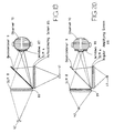
- The 3D display shown in Figure 1 comprises a first autostereoscopic display arrangement comprising a plurality of
light sources 1 and acontrol circuit 2 for sequentially illuminating thelight sources 1. Fourlight sources 1 are shown spaced apart laterally with a pitch which is substantially equal to the lateral width of each of thelight sources 1. An optical system shown in the drawing as alens 3 is disposed between thelight sources 1 and a spatial light modulator (SLM) 4. Alternatively, the SLM 4 may be disposed between thelight sources 1 and thelens 3 and adjacent thelens 3. - The
SLM 4 may comprise a liquid crystal device and is arranged to display a plurality of 2D views in sequence such that each view is illuminated by a respective one of thelight sources 1. The 2D views are thus visible from different angles corresponding to the angles at which the views were recorded during image capture. - The display further comprises a second autostereoscopic display arrangement comprising a plurality of
light sources 5, acontrol circuit 6, alens 7, and anSLM 8 which are substantially identical to thelight sources 1, thecontrol circuit 2, thelens 3, and theSLM 4, respectively. - The views from the two temporally multiplexed display arrangements are combined by means of an optical combining system shown in the drawing as a
beam splitter 9. The views reproduced by theSLM 4 are transmitted through thebeam splitter 9 towards anobserver 10 whereas the views from theSLM 8 are reflected by thebeam splitter 9 towards theobserver 10. Figure 2 illustrates the directions in which the views from the two temporally multiplexed display arrangements are projected towards thebeam splitter 9. Figure 3 shows the apparent light source positions and directionality as perceived by theobserver 10 via thebeam splitter 9. Each 3D image component fills a defined range of image output angles with the components from the two display arrangements being interlaced with each other so that a laterally continuous spread of light emerges from the display. A reconstruction of the 3D image is thus observed over a continuous range of angles by a suitably positionedobserver 10. - The 2D images reproduced by means of the
SLM 8 are laterally inverted by thebeam splitter 9. Compensation for this may be provided by laterally inverting the 2D views in theSLM 8. - The
beam splitter 9 may comprise any device or system which is capable of performing the optical combining function. For instance, thebeam splitter 9 may comprise a partially silvered mirror. Alternatively, in order to reduce the absorption of incident light caused by metallic coatings, all-dielectric non-polarising coatings may be used. However, such coatings are usually designed for particular wavelengths and may thus be of limited application. A hybrid metal-dielectric coating combines the benefits of metals and dielectrics to provide a beam splitter of moderate absorption, low polarisation sensitivity, and good broadband spectral flatness. - Figure 4 shows a display which comprises two spatially multiplexed display arrangements in place of the temporally multiplexed display arrangements of Figure 1. The SLM's 4 and 8, the
beam splitter 9, and theobserver 10 correspond to those shown in Figure 1. However, theSLM 4 is illuminated by means of a diffuselight source 11 and the modulated light emerging from theSLM 4 passes through alenticular screen 12 which comprises a plurality of plano-cylindrical converging lenticules disposed with a regular lateral pitch. Similarly, a diffuselight source 13 and alenticular screen 14 are provided for theSLM 8. - Each of the SLM's 4 and 8 simultaneously produces a plurality of interlaced 2D views made up of thin vertical picture elements. A plurality of such picture elements from different views is displayed behind each of the lenticules of the
screens beam splitter 9 so as to give an apparent picture element position and directionality as illustrated in Figure 6. Thus, as in the embodiment of Figure 1, the reconstructed 3D image is observed over a continuous range of angles by a suitably positioned observer. - In order to increase the number of available views, the techniques of spatial and temporal multiplexing may be combined as illustrated in the display of Figure 7. The
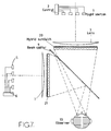
light sources control circuits lenses beam splitter 9 are the same as shown in Figure 1. However, the SLM's 4 and 8 of Figure 1 are replaced byhybrid sandwiches - The
light sources control circuits hybrid sandwiches beam splitter 9 combines the views so that theobserver 10 can observe the 3D image over a continuous range of angles. - The displays shown in Figures 1 to 7 each comprise a
single beam splitter 9 co-operating with two display arrangements to increase the number of 2D views which can be provided to form a composite 3D image. However, a plurality of beam splitters may be provided and the display shown in Figure 8 comprises twobeam splitters light sources 31, acontrol circuit 32, alens 33, and ahybrid sandwich 34 which are substantially identical to thelight sources 1, thecontrol circuit 2, thelens 3, and thehybrid sandwich 20, respectively. The views from thehybrid sandwich 20 are transmitted directly through thebeam splitters observer 10. The views from thehybrid sandwich 21 are reflected by thebeam splitter 9 and transmitted through thebeam splitter 29 to theobserver 10. The views from thehybrid sandwich 34 are reflected by thebeam splitter 29 towards theobserver 10. It is therefore possible to provide a larger number of 2D views to form the composite 3D image. - Figure 9 shows a 3D display of relatively simple type for providing two views. The display of Figure 9 resembles that of Figure 1 but differs in that the
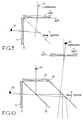
light sources control circuits light sources - Figure 10 shows a 3D display which is similar to that of Figure 9 but which includes a
further beam splitter 29,lens 43, andSLM 44. The display of Figure 10 has three continuously illuminatedlight sources light sources light source 52 is on the axis of thelens 43 whereas thelight sources lenses beam splitter 9 are laterally contiguous with each other. - The display shown in Figure 11 differs from that shown in Figure 1 in that the
light sources 5 and thecontrol circuit 6 are omitted and a beam splitting arrangement is provided so as to divide the light from the light sources 1 (only two shown in Figure 11) so as to illuminate both SLM's 4 and 8. Light from thelight sources 1 is divided by abeam splitter 56, for instance of the same type as thebeam splitter 9, into a transmitted beam and a reflected beam. The transmitted beam is reflected by amirror 57 towards the lens 3 (for instance of the Fresnel type) and theSLM 4. The reflected beam is reflected by amirror 58 towards thelens 7 and theSLM 8. Thebeam splitter 56 is arranged to divide the light into the two beams of equal intensities. Themirrors light source 1 gives rise to two apparent light sources being imaged at the eyes of theobserver 10 with the appropriate interocular separation therebetween after recombination by thebeam splitter 9. - This arrangement provides a simplified display by eliminating one control circuit and set of light sources. Further, problems associated with matching the
light sources - A disadvantage of the display shown in Figure 11 compared with that of Figure 1 is that half the amount of light is provided because half the number of sources are provided. This can be compensated by means of the embodiment shown in Figure 12. The display of Figure 12 differs from that of Figure 11 in that the beam splitter 36 is of the polarising type and divides the light into two orthogonal polarisation components as indicated by the
arrows 59 and 60. The SLM's 4 and 8 are of the liquid crystal display (LCD) type incorporating polariser sheets which are arranged to be orthogonal to each other. Further, thebeam splitter 9 is of the polarisation sensitive type, so that substantially all of the light propagating through the apparatus is directed towards theobserver 10. - The display shown in Figure 12 can be viewed only from the direction of the
observer 10, whereas the display of Figure 11 can also be viewed from the observer position indicated at 10'. For many applications, this is not a disadvantage whereas the increased brightness provided by the display of Figure 12 is an advantage. - The embodiments of Figures 11 and 12 may be modified by omitting the
control circuit 2 and providing a singlelight source 1 so as to provide two 2D views. - The display shown in Figure 13 is similar to the display shown in Figure 1 but employs folded light paths for illuminating the SLM's 4 and 8 using
mirrors light sources light sources LCD shutters 63 and 64. The shutters are controlled by a control circuit of the type shown at 2 and 6 in Figure 1 and operating in the same way so as to provide effectively a plurality of light sources which are illuminated in turn. - By folding the light paths from the light sources to the SLM's 4 and 8 as shown in Figure 13, it is possible to provide a relatively compact display. By using two light sources, the brightness of the display can be increased with respect to the display shown in Figure 11.
- The
LCD shutters shutter 63 and the input polarisation of theSLM 4 may be -45° whereas the output polarisation of theshutter 65 and the input polarisation of theSLM 8 may be +45°. Such an arrangement minimises the light loss occurring because of the use of LCD shutters. - The display shown in Figure 14 resembles that shown in Figure 4 in that it comprises SLM's 4 and 8, a
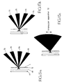
beam combiner 9, diffuse light sources for instance in the form oflight boxes lenticular screens lenticular screens light sources parallax barriers lenticular screens parallax barriers - Operation of the display shown in Figure 14 is illustrated in Figures 15a to 15c. Figure 15a illustrates the light beams 70 produced by a typical lenticule of the
screen 12. Light emanating from four of the slits of theparallax barrier 68 adjacent the lenticule are imaged by the lenticule at observer locations. Figure 15b is a similar view showing the light beams 71 produced by thelenticular screen 14. Again, the slits of thebarrier 69 are imaged at observer locations. - The positions of the slits of the
parallax barriers lenticular screens beam combiner 9 produces a light output pattern as illustrated in Figure 15c. Thus, the light beams 70 and 71 are interlaced with each other and the slits of theparallax barriers effective pitch 72 equal to the average interocular separation. - The illumination system of the display of Figure 14 is compact and therefore permits a relatively compact display to be provided. Further, the design of the
lenticular screens screens observer 10. The actual pitch of the parallax barrier is controlled so that "windows" are generated at theobserver 10 from the entire screen. - As in the case of the other embodiments of the invention, the lenticular screens may be replaced by microlens screens to provide both vertical and horizontal parallax.
- The display shown in Figure 11 has a single illumination arrangement, which may comprise one
light source 1 as shown in Figure 17 or a plurality of light sources as shown in Figure 11, and together with the beam splitter 36 generates two apparent illumination arrangements. The images of the illumination arrangements have to be split in order for theobserver 10 to see two "windows", each modulated by arespective SLM windows - Figure 17 shows a display which is similar to that shown in Figure 11. However, the display of Figure 17 provides a single
light source 1 and each of the SLM's 4 and 8 provides a single view. Further, themirrors lens axis 77 of thelens 3 is laterally displaced from thedisplay axis 78 and theaxis 79 of thelens 7 is laterally displaced from thedisplay axis 80 in order to split the images of theilluminator 1 at theobserver 10. This provideswindows adjacent edges 83. - Although the display of Figure 17 has a single
light source 1 and provides two views, it may have a plurality of light sources and provide more than two views as in the case of the display of Figure 11. Similarly, the display of Figure 11 may be modified to have a single light source and to provide two views. - Figures 19 and 20 show displays of the type shown in Figure 9 but which the
lenses autocollimating screens screens lenses windows 87 produced by imaging thelight sources observer 10 are of substantially the same size as thelight sources - In the display shown in Figure 20, the autocollimating screens are replaced by angular amplifying screens 88 and 89. Each of the
screens screens windows 90 at the observer which are larger than thelight sources - Each of the
screens light sources lenses - The display shown in Figure 21 is of the same type as the display shown in Figure 9. However, the display of Figure 21 differs in the orientation of the various elements. Thus, the
SLM 4 is arranged vertically whereas theSLM 8 is arranged horizontally, as opposed to the display of Figure 9 and all of the other embodiments in which the SLM's are all arranged vertically. Similarly, one or more of the SLM's in all of the other embodiments may be arranged horizontally, should such a configuration be preferable in any application. - Displays of the type shown in the drawings may be used in 3D television, 3D computer aided design and graphics, 3D medical imaging, virtual reality, and computer games. By providing an increased number of 2D views to make up the 3D image, the accuracy and effectiveness of the 3D images can be increased and the maximum display sizes and freedom of viewer location can be increased. Further, moving opaque colour autostereoscopic 3D images from a range of perspectives may be reproduced.
Claims (26)
- An autostereoscopic directional display apparatus comprising a plurality of displays and an optical combining system (9, 29) for combining outputs of the displays, characterised in that each of the displays comprises an autostereoscopic display and co-operates with the optical combining system (9, 29) to provide a plurality of views which are visible in respective different directions.
- An apparatus as claimed in Claim 1, characterised in that each of the directions in which the views are visible comprises an angular range.
- An apparatus as claimed in Claim 2, characterised in that the angular ranges are angularly contiguous in a lateral plane.
- An apparatus as claimed in any one of the preceding claims, in that the directions in which the views provided by each of the displays and the optical combining system (9, 29) are visible are different from the directions in which the views provided by the or each other of the displays and the optical combining system (9, 29) are visible.
- An apparatus as claimed in Claim 4, characterised in that the directions in which the views provided by each of the displays are visible are interlaced with the directions in which the views provided by the or each other of the displays are visible.
- An apparatus as claimed in any one of the preceding claims, characterised in that each of the displays comprises a temporally multiplexed display.
- An apparatus as claimed in Claim 6, characterised in that each of the displays comprises a spatial light modulator (4, 8), an optical system (3, 7), and a plurality of sequentially illuminatable light sources (1, 5) arranged to illuminate the spatial light modulator (4, 8) at respective different angles via the optical system (3, 7).
- An apparatus as claimed in any one of Claims 1 to 5, characterised in that each of the displays comprises a spatially multiplexed display.
- An apparatus as claimed in Claim 8, characterised in that each of the displays comprises a spatial light modulator (4, 8), a diffuse light source (11, 13) for illuminating the spatial light modulator (4, 8), and an array of lenses (12, 14) or a parallax barrier disposed between the spatial light modulator (4, 8) and the optical combining system (9, 29).
- An apparatus as claimed in Claim 9, characterised in that each of the arrays of lenses comprises a lenticular screen (12, 14).
- An apparatus as claimed in any one of Claims 1 to 5, characterised in that each of the displays comprises a temporally and spatially multiplexed display.
- An apparatus as claimed in Claim 11, characterised in that each of the displays comprises a spatial light modulator, a first array of lenses or a first parallax barrier having a first pitch disposed adjacent a first side of the spatial light modulator, a second array of lenses or a second parallax barrier having a second pitch greater than the first pitch disposed adjacent a second side of the spatial light modulator between the spatial light modulator and the optical combining system (9, 29), an optical system (3, 7), and a plurality of sequentially illuminatable light sources (1, 5) arranged to illuminate the first array of lenses or the first parallax barrier at respective different angles via the optical system (3, 7).
- An apparatus as claimed in Claim 7 or 12, characterised by beam splitting means (56, 57, 58) disposed between the light sources (1), which are common to the displays, and the spatial light modulators (4, 8).
- An apparatus as claimed in Claim 13, characterised in that the beam splitting means comprises a beam splitter (56) for splitting light from the light sources (1) into a plurality of beams and a plurality of mirrors (57, 58), each of which is arranged to reflect a respective beam towards a respective one of the spatial light modulators (4, 8).
- An apparatus as claimed in Claim 14, characterised in that the beam splitter (56) and the optical combining system (9, 29) are polarisation-sensitive so that substantially all of the light from the beam splitter (56) is supplied by the optical combining system (9, 29) to a single observer region.
- An apparatus as claimed in Claim 7 or 12, characterised in that the light sources of each of the displays comprise a diffuse light source (42, 44) disposed behind respective shutters (43, 45).
- An apparatus as claimed in Claim 16, characterised in that the light paths from the shutters (63, 65) cross each other and intersect respective mirrors (57, 58) arranged to reflect light towards the respective spatial light modulators (4, 8).
- An apparatus as claimed in Claim 16 or 17, characterised in that each of the shutters (63, 65) has an output polarisation which matches an input polarisation of the respective spatial light modulator (4, 8).
- An apparatus as claimed in any one of the preceding claims, characterised in that the optical combining system (9, 29) comprises at least one beam combiner having an optically transmissive path and an optically reflective path.
- An autostereoscopic display apparatus comprising a plurality of displays and an optical combining system (9, 29) for combining the outputs of the displays, characterised in that each of the displays comprises a light source (1, 5, 11, 13, 31, 41, 42, 51-53, 62, 64), a light-transmissive spatial light modulator (4, 8, 20, 21, 34, 44) arranged to modulate light spatial light source (1, 5, 11, 12, 31, 41, 42, 51-53, 62, 64) with an image to be viewed, and a lens arrangement (3, 7, 12, 14, 20, 21, 34, 43, 85, 86, 88, 89) disposed adjacent the spatial light modulator (4, 8, 20, 21, 34, 44) and arranged to image the light source (1, 5, 11, 13, 31, 41, 42, 51-53, 62, 64) at a viewing window (87, 90) at (1, 5, 11, 13, 31, 41, 42, 51-53, 62, 64) at a viewing window (87, 90) at an observer location (10) via the optical combining system (9, 29).
- An apparatus as claimed in Claim 20, characterised in that the light sources of the displays comprise a common light source (1), a beam splitter (56) for dividing light from the common light source (1) into a plurality of beams, and at least one reflector (57, 58) for reflecting a respective one of the beams towards the spatial light modulator (4, 8) of a respective one of the displays.
- An apparatus as claimed in Claim 21, characterised each of the displays has an optical axis (78, 80) and each of the lens arrangements (3, 7) has an optical axis (77, 79) which is laterally displaced from the optical axis (78, 80) of the respective display.
- An apparatus as claimed in Claim 20, characterised in that, for each of the displays, the light source comprises a diffuse light source (11, 13), the lens arrangement comprises an array (12, 14) of lenses, and a parallax barrier (68, 69) is disposed between the light source (11, 13) and the array (12, 14) of lenses in an object plane of the array (12, 14) of lenses.
- An apparatus as claimed in Claim 20, characterised in that each of the lens arrangements comprises an autocollimating screen (85, 86).
- An apparatus as claimed in Claim 20, characterised in that each of the lens arrangements comprises an angular amplifying screen (88, 89).
- An apparatus as claimed in any one of Claims 20 to 25, characterised in that, for each of the displays, the light source (1, 5, 11, 13, 31, 41, 42, 51-53, 62, 64) comprises a single light source and the spatial light modulator (4, 8, 44) is arranged to modulate light with an image representing a view from a single predetermined direction.
Priority Applications (1)
| Application Number | Priority Date | Filing Date | Title |
|---|---|---|---|
| EP96118828A EP0764869B1 (en) | 1992-12-17 | 1993-12-14 | Autostereoscopic display apparatus |
Applications Claiming Priority (4)
| Application Number | Priority Date | Filing Date | Title |
|---|---|---|---|
| GB9226272A GB2273577A (en) | 1992-12-17 | 1992-12-17 | Autostereoscopic directional display apparatus |
| GB9226272 | 1992-12-17 | ||
| GB9324703A GB2284487A (en) | 1993-12-01 | 1993-12-01 | Display for 3D images |
| GB9324703 | 1993-12-01 |
Related Child Applications (1)
| Application Number | Title | Priority Date | Filing Date |
|---|---|---|---|
| EP96118828A Division EP0764869B1 (en) | 1992-12-17 | 1993-12-14 | Autostereoscopic display apparatus |
Publications (3)
| Publication Number | Publication Date |
|---|---|
| EP0602934A2 true EP0602934A2 (en) | 1994-06-22 |
| EP0602934A3 EP0602934A3 (en) | 1995-03-01 |
| EP0602934B1 EP0602934B1 (en) | 1999-03-10 |
Family
ID=26302168
Family Applications (2)
| Application Number | Title | Priority Date | Filing Date |
|---|---|---|---|
| EP96118828A Expired - Lifetime EP0764869B1 (en) | 1992-12-17 | 1993-12-14 | Autostereoscopic display apparatus |
| EP93310071A Expired - Lifetime EP0602934B1 (en) | 1992-12-17 | 1993-12-14 | Autostereoscopic directional display apparatus |
Family Applications Before (1)
| Application Number | Title | Priority Date | Filing Date |
|---|---|---|---|
| EP96118828A Expired - Lifetime EP0764869B1 (en) | 1992-12-17 | 1993-12-14 | Autostereoscopic display apparatus |
Country Status (4)
| Country | Link |
|---|---|
| US (1) | US5726800A (en) |
| EP (2) | EP0764869B1 (en) |
| JP (1) | JP3151347B2 (en) |
| DE (2) | DE69323846T2 (en) |
Cited By (21)
| Publication number | Priority date | Publication date | Assignee | Title |
|---|---|---|---|---|
| EP0653891A1 (en) * | 1993-11-12 | 1995-05-17 | Sharp Kabushiki Kaisha | Three-dimensional projection display apparatus |
| WO1995034173A1 (en) * | 1994-06-07 | 1995-12-14 | Terumo Kabushiki Kaisha | Image display apparatus |
| EP0721130A2 (en) * | 1994-12-16 | 1996-07-10 | Sharp Kabushiki Kaisha | Display |
| EP0721131A2 (en) * | 1994-12-29 | 1996-07-10 | Sharp Kabushiki Kaisha | Observer tracking autostereoscopic display and method of tracking an observer |
| EP0708351A3 (en) * | 1994-10-21 | 1996-07-31 | Sharp Kk | Light source and display |
| EP0724176A2 (en) * | 1995-01-28 | 1996-07-31 | Sharp Kabushiki Kaisha | Three-dimensional display |
| EP0726482A2 (en) * | 1995-02-09 | 1996-08-14 | Sharp Kabushiki Kaisha | Autostereoscopic display and method of controlling an autostereoscopic display |
| EP0729054A1 (en) * | 1995-02-25 | 1996-08-28 | Lüder, Ernst, Prof. Dr.-Ing. habil. | Device and method for autostereoscopically displaying three-dimensional structures |
| US5568314A (en) * | 1993-12-03 | 1996-10-22 | Terumo Kabushiki Kaisha | Image display apparatus |
| EP0762177A2 (en) * | 1995-09-06 | 1997-03-12 | THOMSON multimedia | Stereoscopic display using a lenticular lens sheet |
| US5644427A (en) * | 1994-02-07 | 1997-07-01 | Terumo Kabushiki Kaisha | Image display apparatus |
| US5774261A (en) * | 1993-11-19 | 1998-06-30 | Terumo Kabushiki Kaisha | Image display system |
| US5818399A (en) * | 1994-02-09 | 1998-10-06 | Terumo Kabushiki Kaisha | Image communication apparatus |
| EP0881844A2 (en) * | 1997-05-27 | 1998-12-02 | Sanyo Electric Co. Ltd | Head position detecting device and head tracking stereoscopic display |
| US5976017A (en) * | 1994-02-09 | 1999-11-02 | Terumo Kabushiki Kaisha | Stereoscopic-image game playing apparatus |
| US6054969A (en) * | 1995-03-08 | 2000-04-25 | U.S. Philips Corporation | Three-dimensional image display system |
| US6055103A (en) * | 1997-06-28 | 2000-04-25 | Sharp Kabushiki Kaisha | Passive polarisation modulating optical element and method of making such an element |
| US6075557A (en) * | 1997-04-17 | 2000-06-13 | Sharp Kabushiki Kaisha | Image tracking system and method and observer tracking autostereoscopic display |
| US6115058A (en) * | 1993-12-03 | 2000-09-05 | Terumo Kabushiki Kaisha | Image display system |
| WO2005024493A1 (en) * | 2003-08-28 | 2005-03-17 | Eastman Kodak Company | Autostereoscopic display for multiple viewers |
| EP3687860A4 (en) * | 2017-09-27 | 2020-08-05 | Gentex Corporation | Full display mirror with accommodation correction |
Families Citing this family (37)
| Publication number | Priority date | Publication date | Assignee | Title |
|---|---|---|---|---|
| CN1154878C (en) | 1995-06-02 | 2004-06-23 | 松下电器产业株式会社 | Optical device, laser beam source, laser apparatus and method of producing optical device |
| US5936774A (en) * | 1995-08-29 | 1999-08-10 | Street; Graham S. B. | Autostereoscopic display |
| GB2314203B (en) * | 1996-06-15 | 2000-11-08 | Ibm | Auto-stereoscopic display device and system |
| DE69830441T2 (en) * | 1997-03-28 | 2005-12-08 | Seiko Epson Corp. | Optical illumination system and projection type display device |
| US6229562B1 (en) * | 1997-07-08 | 2001-05-08 | Stanley H. Kremen | System and apparatus for the recording and projection of images in substantially 3-dimensional format |
| GB2337388A (en) | 1998-05-12 | 1999-11-17 | Sharp Kk | Directional autereoscopic 3D display having directional illumination system |
| US6525699B1 (en) | 1998-05-21 | 2003-02-25 | Nippon Telegraph And Telephone Corporation | Three-dimensional representation method and an apparatus thereof |
| US6351280B1 (en) | 1998-11-20 | 2002-02-26 | Massachusetts Institute Of Technology | Autostereoscopic display system |
| US7092003B1 (en) | 1999-01-21 | 2006-08-15 | Mel Siegel | 3-D imaging arrangements |
| WO2000044180A1 (en) * | 1999-01-21 | 2000-07-27 | Mel Siegel | 3-d imaging arrangements |
| JP4245750B2 (en) * | 1999-10-15 | 2009-04-02 | オリンパス株式会社 | Stereoscopic observation device |
| JP2004511000A (en) * | 2000-06-14 | 2004-04-08 | パノラム テクノロジーズ,インコーポレイテッド. | Method and apparatus for seamless integration of multiple images using transmission / reflection mirrors |
| US7136031B2 (en) * | 2000-12-18 | 2006-11-14 | Byoungho Lee | Reflecting three-dimensional display system |
| WO2003012527A1 (en) * | 2001-07-31 | 2003-02-13 | Oleg Leonidovich Golovkov | Device for indicating a stereoscopic image |
| KR20010088919A (en) * | 2001-08-01 | 2001-09-29 | 김정호 | 3-dimensional image generating device for generating two identical 3-dimensional images by dividing 3-dimensional image using two concave mirrors or flat mirrors |
| EP1459568A1 (en) * | 2001-12-14 | 2004-09-22 | Koninklijke Philips Electronics N.V. | Stereoscopic display apparatus and system |
| RU2006104222A (en) * | 2003-07-18 | 2013-10-27 | Владимир Викторович Фетискин | DEVICE FOR STEREOSCOPIC IMAGE INDICATION |
| WO2005008316A1 (en) * | 2003-07-18 | 2005-01-27 | Oleg Leonidovich Golovkov | Device for displaying three-dimensional images |
| CN100429559C (en) * | 2003-08-22 | 2008-10-29 | 株式会社电装 | Virtual image display apparatus |
| JP2005070255A (en) * | 2003-08-22 | 2005-03-17 | Denso Corp | Virtual image display device |
| US6834961B1 (en) | 2003-09-12 | 2004-12-28 | Eastman Kodak Company | Autostereoscopic optical apparatus |
| US6871956B1 (en) | 2003-09-12 | 2005-03-29 | Eastman Kodak Company | Autostereoscopic optical apparatus |
| US7226167B2 (en) | 2004-05-25 | 2007-06-05 | Eastman Kodak Company | Autostereoscopic display apparatus |
| DE102005040597A1 (en) * | 2005-02-25 | 2007-02-22 | Seereal Technologies Gmbh | Method and device for tracking sweet spots |
| US7926949B1 (en) * | 2006-07-22 | 2011-04-19 | Simon Boothroyd | Dual-mode three-dimensional projection display |
| US7750982B2 (en) | 2008-03-19 | 2010-07-06 | 3M Innovative Properties Company | Autostereoscopic display with fresnel lens element and double sided prism film adjacent a backlight having a light transmission surface with left and right eye light sources at opposing ends modulated at a rate of at least 90 hz |
| JP4719929B2 (en) * | 2009-03-31 | 2011-07-06 | Necカシオモバイルコミュニケーションズ株式会社 | Display device and program |
| US8203600B2 (en) * | 2009-06-04 | 2012-06-19 | Transpacific Image, Llc | Projection-type stereoscopic display |
| US7978407B1 (en) | 2009-06-27 | 2011-07-12 | Holovisions LLC | Holovision (TM) 3D imaging with rotating light-emitting members |
| JP2012125453A (en) * | 2010-12-16 | 2012-07-05 | Fujifilm Corp | Display device |
| JP2013231873A (en) * | 2012-04-27 | 2013-11-14 | Panasonic Corp | Video display device |
| KR101371772B1 (en) * | 2013-01-28 | 2014-03-10 | 가톨릭대학교 산학협력단 | Stereovision optometry apparatus |
| DE102015215106A1 (en) * | 2015-08-07 | 2017-02-09 | Robert Bosch Gmbh | An imaging unit for a head-up display, head-up display and method for generating stereoscopic fields by means of an imager unit |
| EP3163358B1 (en) * | 2015-10-29 | 2018-03-28 | X-Rite Switzerland GmbH | Visualisation device |
| CN105607454B (en) * | 2016-01-25 | 2018-06-29 | 京东方科技集团股份有限公司 | Holographic display and holographic display methods |
| KR101831748B1 (en) * | 2016-10-11 | 2018-02-26 | 전자부품연구원 | Autostereoscopic 3d display apparatus |
| CN217778499U (en) | 2019-11-07 | 2022-11-11 | 金泰克斯公司 | Display device |
Citations (6)
| Publication number | Priority date | Publication date | Assignee | Title |
|---|---|---|---|---|
| WO1983002169A1 (en) * | 1981-12-07 | 1983-06-23 | Anthony Charles Rackham | Stereoscopic pictures |
| JPS61113389A (en) * | 1984-11-07 | 1986-05-31 | Mitsubishi Heavy Ind Ltd | Time-division stereoscopic equipment |
| EP0262955A2 (en) * | 1986-09-30 | 1988-04-06 | Martin Lawrence Bass | Display means for stereoscopic images |
| DE4004739A1 (en) * | 1990-02-15 | 1991-08-22 | Holtronic Gmbh | Optical system for stereoscopic information display - uses left and right hand light sources activated in alternation for illuminating display |
| EP0508824A1 (en) * | 1991-04-12 | 1992-10-14 | Sharp Kabushiki Kaisha | A three-dimensional image display apparatus |
| WO1993019394A2 (en) * | 1992-03-20 | 1993-09-30 | Delta Systems Design Limited | Twin screen imaging system |
Family Cites Families (15)
| Publication number | Priority date | Publication date | Assignee | Title |
|---|---|---|---|---|
| US1992872A (en) * | 1933-11-07 | 1935-02-26 | Mahler Josef | Stereoscopic apparatus |
| US2550350A (en) * | 1948-07-08 | 1951-04-24 | Henson West | Lens screen to produce stereoscopic effects |
| US2883906A (en) * | 1952-02-04 | 1959-04-28 | Rehorn Miles Parker | Stereoscopic system and apparatus |
| GB1121097A (en) | 1965-10-05 | 1968-07-24 | Leo Cahn | Three dimensional picture |
| AT303575B (en) | 1970-08-25 | 1972-11-27 | Swarovski & Co | Motion picture |
| US4190856A (en) | 1977-11-21 | 1980-02-26 | Ricks Dennis E | Three dimensional television system |
| JPS5694887A (en) | 1979-12-27 | 1981-07-31 | Sony Corp | Projecting device |
| US4623223A (en) | 1982-12-27 | 1986-11-18 | Kempf Paul S | Stereo image display using a concave mirror and two contiguous reflecting mirrors |
| US4535354A (en) * | 1983-03-24 | 1985-08-13 | Rickert Glenn E | Projected stereoscopic picture separation |
| NL8500141A (en) * | 1985-01-21 | 1986-08-18 | Delft Tech Hogeschool | METHOD FOR GENERATING A THREE-DIMENSIONAL IMPRESSION FROM A TWO-DIMENSIONAL IMAGE AT AN OBSERVER |
| GB2185825B (en) | 1986-01-23 | 1990-08-01 | John Charles Sanderson | Spatial stereoscopic image system using concave mirror |
| GB8716369D0 (en) * | 1987-07-10 | 1987-08-19 | Travis A R L | Three-dimensional display device |
| US5003385A (en) * | 1988-08-24 | 1991-03-26 | Kabushiki Kaisha Toshiba | Stereoscopic television system |
| DE3921061A1 (en) * | 1989-06-23 | 1991-01-03 | Hertz Inst Heinrich | DISPLAY DEVICE FOR THREE-DIMENSIONAL PERCEPTION OF IMAGES |
| GB2267579A (en) | 1992-05-15 | 1993-12-08 | Sharp Kk | Optical device comprising facing lenticular or parallax screens of different pitch |
-
1993
- 1993-12-14 DE DE69323846T patent/DE69323846T2/en not_active Expired - Lifetime
- 1993-12-14 DE DE69331114T patent/DE69331114T2/en not_active Expired - Lifetime
- 1993-12-14 EP EP96118828A patent/EP0764869B1/en not_active Expired - Lifetime
- 1993-12-14 EP EP93310071A patent/EP0602934B1/en not_active Expired - Lifetime
- 1993-12-15 US US08/167,497 patent/US5726800A/en not_active Expired - Lifetime
- 1993-12-16 JP JP31715493A patent/JP3151347B2/en not_active Expired - Fee Related
Patent Citations (6)
| Publication number | Priority date | Publication date | Assignee | Title |
|---|---|---|---|---|
| WO1983002169A1 (en) * | 1981-12-07 | 1983-06-23 | Anthony Charles Rackham | Stereoscopic pictures |
| JPS61113389A (en) * | 1984-11-07 | 1986-05-31 | Mitsubishi Heavy Ind Ltd | Time-division stereoscopic equipment |
| EP0262955A2 (en) * | 1986-09-30 | 1988-04-06 | Martin Lawrence Bass | Display means for stereoscopic images |
| DE4004739A1 (en) * | 1990-02-15 | 1991-08-22 | Holtronic Gmbh | Optical system for stereoscopic information display - uses left and right hand light sources activated in alternation for illuminating display |
| EP0508824A1 (en) * | 1991-04-12 | 1992-10-14 | Sharp Kabushiki Kaisha | A three-dimensional image display apparatus |
| WO1993019394A2 (en) * | 1992-03-20 | 1993-09-30 | Delta Systems Design Limited | Twin screen imaging system |
Non-Patent Citations (1)
| Title |
|---|
| PATENT ABSTRACTS OF JAPAN vol. 10, no. 297 (E-444) 9 October 1986 & JP-A-61 113 389 (MITSUBISHI) 31 May 1986 * |
Cited By (37)
| Publication number | Priority date | Publication date | Assignee | Title |
|---|---|---|---|---|
| US5703717A (en) * | 1993-11-12 | 1997-12-30 | Sharp Kabushiki Kaisha | Three-dimensional projection display apparatus |
| EP0653891A1 (en) * | 1993-11-12 | 1995-05-17 | Sharp Kabushiki Kaisha | Three-dimensional projection display apparatus |
| EP0654951B1 (en) * | 1993-11-19 | 1999-12-01 | Terumo Kabushiki Kaisha | Stereoscopic image display system |
| US5774261A (en) * | 1993-11-19 | 1998-06-30 | Terumo Kabushiki Kaisha | Image display system |
| US6115058A (en) * | 1993-12-03 | 2000-09-05 | Terumo Kabushiki Kaisha | Image display system |
| US5568314A (en) * | 1993-12-03 | 1996-10-22 | Terumo Kabushiki Kaisha | Image display apparatus |
| US5644427A (en) * | 1994-02-07 | 1997-07-01 | Terumo Kabushiki Kaisha | Image display apparatus |
| US5818399A (en) * | 1994-02-09 | 1998-10-06 | Terumo Kabushiki Kaisha | Image communication apparatus |
| US5976017A (en) * | 1994-02-09 | 1999-11-02 | Terumo Kabushiki Kaisha | Stereoscopic-image game playing apparatus |
| WO1995034173A1 (en) * | 1994-06-07 | 1995-12-14 | Terumo Kabushiki Kaisha | Image display apparatus |
| US6011580A (en) * | 1994-06-07 | 2000-01-04 | Terumo Kabushiki Kaisha | Image display apparatus |
| US6061489A (en) * | 1994-10-12 | 2000-05-09 | Sharp Kabushiki Kaisha | Light source and display |
| EP0708351A3 (en) * | 1994-10-21 | 1996-07-31 | Sharp Kk | Light source and display |
| EP0721130A3 (en) * | 1994-12-16 | 1996-07-17 | Sharp Kabushiki Kaisha | Display |
| US5777588A (en) * | 1994-12-16 | 1998-07-07 | Sharp Kabushiki Kaisha | Autostereoscopic display having a high resolution 2D mode |
| EP0721130A2 (en) * | 1994-12-16 | 1996-07-10 | Sharp Kabushiki Kaisha | Display |
| EP0721131A3 (en) * | 1994-12-29 | 1996-07-17 | Sharp Kabushiki Kaisha | Observer tracking autostereoscopic display and method of tracking an observer |
| EP0721131A2 (en) * | 1994-12-29 | 1996-07-10 | Sharp Kabushiki Kaisha | Observer tracking autostereoscopic display and method of tracking an observer |
| US5959664A (en) * | 1994-12-29 | 1999-09-28 | Sharp Kabushiki Kaisha | Observer tracking autostereoscopic display and method of tracking an observer |
| US6449090B1 (en) | 1995-01-28 | 2002-09-10 | Sharp Kabushiki Kaisha | Three dimensional display viewable in both stereoscopic and autostereoscopic modes |
| EP0724176A3 (en) * | 1995-01-28 | 1996-11-13 | Sharp Kk | Three-dimensional display |
| EP0724176A2 (en) * | 1995-01-28 | 1996-07-31 | Sharp Kabushiki Kaisha | Three-dimensional display |
| EP0726482A3 (en) * | 1995-02-09 | 1996-11-13 | Sharp Kk | Autostereoscopic display and method of controlling an autostereoscopic display |
| EP0726482A2 (en) * | 1995-02-09 | 1996-08-14 | Sharp Kabushiki Kaisha | Autostereoscopic display and method of controlling an autostereoscopic display |
| US5808792A (en) * | 1995-02-09 | 1998-09-15 | Sharp Kabushiki Kaisha | Autostereoscopic display and method of controlling an autostereoscopic display |
| EP0729054A1 (en) * | 1995-02-25 | 1996-08-28 | Lüder, Ernst, Prof. Dr.-Ing. habil. | Device and method for autostereoscopically displaying three-dimensional structures |
| US5777787A (en) * | 1995-02-25 | 1998-07-07 | Ernst Lueder | Apparatus and process for autostereoscopic viewing of a three-dimensional structure |
| US6054969A (en) * | 1995-03-08 | 2000-04-25 | U.S. Philips Corporation | Three-dimensional image display system |
| EP0762177A3 (en) * | 1995-09-06 | 1997-04-02 | THOMSON multimedia | Stereoscopic display using a lenticular lens sheet |
| EP0762177A2 (en) * | 1995-09-06 | 1997-03-12 | THOMSON multimedia | Stereoscopic display using a lenticular lens sheet |
| US6075557A (en) * | 1997-04-17 | 2000-06-13 | Sharp Kabushiki Kaisha | Image tracking system and method and observer tracking autostereoscopic display |
| EP0881844A3 (en) * | 1997-05-27 | 1999-08-04 | Sanyo Electric Co. Ltd | Head position detecting device and head tracking stereoscopic display |
| EP0881844A2 (en) * | 1997-05-27 | 1998-12-02 | Sanyo Electric Co. Ltd | Head position detecting device and head tracking stereoscopic display |
| US6304288B1 (en) | 1997-05-27 | 2001-10-16 | Sanyo Electric Co., Ltd. | Head position detecting device and head tracking stereoscopic display |
| US6055103A (en) * | 1997-06-28 | 2000-04-25 | Sharp Kabushiki Kaisha | Passive polarisation modulating optical element and method of making such an element |
| WO2005024493A1 (en) * | 2003-08-28 | 2005-03-17 | Eastman Kodak Company | Autostereoscopic display for multiple viewers |
| EP3687860A4 (en) * | 2017-09-27 | 2020-08-05 | Gentex Corporation | Full display mirror with accommodation correction |
Also Published As
| Publication number | Publication date |
|---|---|
| DE69323846D1 (en) | 1999-04-15 |
| EP0764869A3 (en) | 1997-04-09 |
| US5726800A (en) | 1998-03-10 |
| DE69331114D1 (en) | 2001-12-13 |
| EP0764869A2 (en) | 1997-03-26 |
| EP0602934A3 (en) | 1995-03-01 |
| JPH06258597A (en) | 1994-09-16 |
| JP3151347B2 (en) | 2001-04-03 |
| EP0764869B1 (en) | 2001-11-07 |
| EP0602934B1 (en) | 1999-03-10 |
| DE69331114T2 (en) | 2002-06-06 |
| DE69323846T2 (en) | 1999-08-26 |
Similar Documents
| Publication | Publication Date | Title |
|---|---|---|
| EP0602934B1 (en) | Autostereoscopic directional display apparatus | |
| US5465175A (en) | Autostereoscopic display device | |
| US6603504B1 (en) | Multiview three-dimensional image display device | |
| US5703717A (en) | Three-dimensional projection display apparatus | |
| EP0601308B1 (en) | Stereoscopic television display | |
| JP3269823B2 (en) | Optical system for two-dimensional and three-dimensional display of information | |
| GB2431728A (en) | Multi-depth displays | |
| JPH04504786A (en) | three dimensional display device | |
| JP3105888B2 (en) | Multi-view 3D video display | |
| US20070139767A1 (en) | Stereoscopic image display apparatus | |
| JPH07504766A (en) | Image forming system with two sets of screens | |
| EP0830630B1 (en) | Stereoscopic display device | |
| JPH05284542A (en) | Three-dimensional picture/two-dimensional picture coexistence type display device | |
| JP3072866B2 (en) | 3D stereoscopic image display device | |
| JP3462796B2 (en) | Three-dimensional display method and device | |
| JP3022559B1 (en) | 3D display system | |
| JP3463960B2 (en) | 3D image display device | |
| GB2273577A (en) | Autostereoscopic directional display apparatus | |
| KR100233801B1 (en) | Image display apparatus for displaying plane and three dimensional images | |
| JP2865616B2 (en) | 3D image display device | |
| AU636228B2 (en) | Apparatus for displaying an image | |
| KR20190083772A (en) | Three-dimensional image projection apparatus | |
| Aye et al. | Multiperspective holographic autostereo 3D display | |
| JPH05197043A (en) | Projection type three-dimensional display device |
Legal Events
| Date | Code | Title | Description |
|---|---|---|---|
| PUAI | Public reference made under article 153(3) epc to a published international application that has entered the european phase |
Free format text: ORIGINAL CODE: 0009012 |
|
| AK | Designated contracting states |
Kind code of ref document: A2 Designated state(s): DE FR GB |
|
| PUAL | Search report despatched |
Free format text: ORIGINAL CODE: 0009013 |
|
| AK | Designated contracting states |
Kind code of ref document: A3 Designated state(s): DE FR GB |
|
| 17P | Request for examination filed |
Effective date: 19950621 |
|
| 17Q | First examination report despatched |
Effective date: 19960404 |
|
| GRAG | Despatch of communication of intention to grant |
Free format text: ORIGINAL CODE: EPIDOS AGRA |
|
| GRAG | Despatch of communication of intention to grant |
Free format text: ORIGINAL CODE: EPIDOS AGRA |
|
| GRAH | Despatch of communication of intention to grant a patent |
Free format text: ORIGINAL CODE: EPIDOS IGRA |
|
| GRAH | Despatch of communication of intention to grant a patent |
Free format text: ORIGINAL CODE: EPIDOS IGRA |
|
| GRAA | (expected) grant |
Free format text: ORIGINAL CODE: 0009210 |
|
| AK | Designated contracting states |
Kind code of ref document: B1 Designated state(s): DE FR GB |
|
| DX | Miscellaneous (deleted) | ||
| REF | Corresponds to: |
Ref document number: 69323846 Country of ref document: DE Date of ref document: 19990415 |
|
| ET | Fr: translation filed | ||
| PLBE | No opposition filed within time limit |
Free format text: ORIGINAL CODE: 0009261 |
|
| STAA | Information on the status of an ep patent application or granted ep patent |
Free format text: STATUS: NO OPPOSITION FILED WITHIN TIME LIMIT |
|
| 26N | No opposition filed | ||
| REG | Reference to a national code |
Ref country code: GB Ref legal event code: IF02 |
|
| PGFP | Annual fee paid to national office [announced via postgrant information from national office to epo] |
Ref country code: GB Payment date: 20091209 Year of fee payment: 17 Ref country code: FR Payment date: 20091221 Year of fee payment: 17 |
|
| PGFP | Annual fee paid to national office [announced via postgrant information from national office to epo] |
Ref country code: DE Payment date: 20091222 Year of fee payment: 17 |
|
| GBPC | Gb: european patent ceased through non-payment of renewal fee |
Effective date: 20101214 |
|
| REG | Reference to a national code |
Ref country code: FR Ref legal event code: ST Effective date: 20110831 |
|
| PG25 | Lapsed in a contracting state [announced via postgrant information from national office to epo] |
Ref country code: FR Free format text: LAPSE BECAUSE OF NON-PAYMENT OF DUE FEES Effective date: 20110103 |
|
| REG | Reference to a national code |
Ref country code: DE Ref legal event code: R119 Ref document number: 69323846 Country of ref document: DE Effective date: 20110701 |
|
| PG25 | Lapsed in a contracting state [announced via postgrant information from national office to epo] |
Ref country code: DE Free format text: LAPSE BECAUSE OF NON-PAYMENT OF DUE FEES Effective date: 20110701 Ref country code: GB Free format text: LAPSE BECAUSE OF NON-PAYMENT OF DUE FEES Effective date: 20101214 |