EP0603748B2 - Methods and apparatus for selectively controlling a spray of liquid to FORM a distinct pattern and use of the method for the fabrication of a disposable absorbent article - Google Patents
Methods and apparatus for selectively controlling a spray of liquid to FORM a distinct pattern and use of the method for the fabrication of a disposable absorbent article Download PDFInfo
- Publication number
- EP0603748B2 EP0603748B2 EP93120315A EP93120315A EP0603748B2 EP 0603748 B2 EP0603748 B2 EP 0603748B2 EP 93120315 A EP93120315 A EP 93120315A EP 93120315 A EP93120315 A EP 93120315A EP 0603748 B2 EP0603748 B2 EP 0603748B2
- Authority
- EP
- European Patent Office
- Prior art keywords
- liquid
- adhesive
- nozzle
- nozzles
- pattern
- Prior art date
- Legal status (The legal status is an assumption and is not a legal conclusion. Google has not performed a legal analysis and makes no representation as to the accuracy of the status listed.)
- Expired - Lifetime
Links
Images


Classifications
-
- B—PERFORMING OPERATIONS; TRANSPORTING
- B05—SPRAYING OR ATOMISING IN GENERAL; APPLYING FLUENT MATERIALS TO SURFACES, IN GENERAL
- B05C—APPARATUS FOR APPLYING FLUENT MATERIALS TO SURFACES, IN GENERAL
- B05C5/00—Apparatus in which liquid or other fluent material is projected, poured or allowed to flow on to the surface of the work
-
- A—HUMAN NECESSITIES
- A61—MEDICAL OR VETERINARY SCIENCE; HYGIENE
- A61F—FILTERS IMPLANTABLE INTO BLOOD VESSELS; PROSTHESES; DEVICES PROVIDING PATENCY TO, OR PREVENTING COLLAPSING OF, TUBULAR STRUCTURES OF THE BODY, e.g. STENTS; ORTHOPAEDIC, NURSING OR CONTRACEPTIVE DEVICES; FOMENTATION; TREATMENT OR PROTECTION OF EYES OR EARS; BANDAGES, DRESSINGS OR ABSORBENT PADS; FIRST-AID KITS
- A61F13/00—Bandages or dressings; Absorbent pads
- A61F13/15—Absorbent pads, e.g. sanitary towels, swabs or tampons for external or internal application to the body; Supporting or fastening means therefor; Tampon applicators
- A61F13/51—Absorbent pads, e.g. sanitary towels, swabs or tampons for external or internal application to the body; Supporting or fastening means therefor; Tampon applicators characterised by the outer layers
- A61F13/515—Absorbent pads, e.g. sanitary towels, swabs or tampons for external or internal application to the body; Supporting or fastening means therefor; Tampon applicators characterised by the outer layers characterised by the interconnection of the topsheet and the backsheet
-
- A—HUMAN NECESSITIES
- A61—MEDICAL OR VETERINARY SCIENCE; HYGIENE
- A61F—FILTERS IMPLANTABLE INTO BLOOD VESSELS; PROSTHESES; DEVICES PROVIDING PATENCY TO, OR PREVENTING COLLAPSING OF, TUBULAR STRUCTURES OF THE BODY, e.g. STENTS; ORTHOPAEDIC, NURSING OR CONTRACEPTIVE DEVICES; FOMENTATION; TREATMENT OR PROTECTION OF EYES OR EARS; BANDAGES, DRESSINGS OR ABSORBENT PADS; FIRST-AID KITS
- A61F13/00—Bandages or dressings; Absorbent pads
- A61F13/15—Absorbent pads, e.g. sanitary towels, swabs or tampons for external or internal application to the body; Supporting or fastening means therefor; Tampon applicators
- A61F13/15577—Apparatus or processes for manufacturing
- A61F13/15699—Forming webs by bringing together several webs, e.g. by laminating or folding several webs, with or without additional treatment of the webs
-
- A—HUMAN NECESSITIES
- A61—MEDICAL OR VETERINARY SCIENCE; HYGIENE
- A61F—FILTERS IMPLANTABLE INTO BLOOD VESSELS; PROSTHESES; DEVICES PROVIDING PATENCY TO, OR PREVENTING COLLAPSING OF, TUBULAR STRUCTURES OF THE BODY, e.g. STENTS; ORTHOPAEDIC, NURSING OR CONTRACEPTIVE DEVICES; FOMENTATION; TREATMENT OR PROTECTION OF EYES OR EARS; BANDAGES, DRESSINGS OR ABSORBENT PADS; FIRST-AID KITS
- A61F13/00—Bandages or dressings; Absorbent pads
- A61F13/15—Absorbent pads, e.g. sanitary towels, swabs or tampons for external or internal application to the body; Supporting or fastening means therefor; Tampon applicators
- A61F13/53—Absorbent pads, e.g. sanitary towels, swabs or tampons for external or internal application to the body; Supporting or fastening means therefor; Tampon applicators characterised by the absorbing medium
- A61F13/539—Absorbent pads, e.g. sanitary towels, swabs or tampons for external or internal application to the body; Supporting or fastening means therefor; Tampon applicators characterised by the absorbing medium characterised by the connection of the absorbent layers with each other or with the outer layers
-
- B—PERFORMING OPERATIONS; TRANSPORTING
- B05—SPRAYING OR ATOMISING IN GENERAL; APPLYING FLUENT MATERIALS TO SURFACES, IN GENERAL
- B05B—SPRAYING APPARATUS; ATOMISING APPARATUS; NOZZLES
- B05B12/00—Arrangements for controlling delivery; Arrangements for controlling the spray area
- B05B12/08—Arrangements for controlling delivery; Arrangements for controlling the spray area responsive to condition of liquid or other fluent material to be discharged, of ambient medium or of target ; responsive to condition of spray devices or of supply means, e.g. pipes, pumps or their drive means
- B05B12/12—Arrangements for controlling delivery; Arrangements for controlling the spray area responsive to condition of liquid or other fluent material to be discharged, of ambient medium or of target ; responsive to condition of spray devices or of supply means, e.g. pipes, pumps or their drive means responsive to conditions of ambient medium or target, e.g. humidity, temperature position or movement of the target relative to the spray apparatus
- B05B12/126—Arrangements for controlling delivery; Arrangements for controlling the spray area responsive to condition of liquid or other fluent material to be discharged, of ambient medium or of target ; responsive to condition of spray devices or of supply means, e.g. pipes, pumps or their drive means responsive to conditions of ambient medium or target, e.g. humidity, temperature position or movement of the target relative to the spray apparatus responsive to target velocity, e.g. to relative velocity between spray apparatus and target
-
- D—TEXTILES; PAPER
- D06—TREATMENT OF TEXTILES OR THE LIKE; LAUNDERING; FLEXIBLE MATERIALS NOT OTHERWISE PROVIDED FOR
- D06B—TREATING TEXTILE MATERIALS USING LIQUIDS, GASES OR VAPOURS
- D06B11/00—Treatment of selected parts of textile materials, e.g. partial dyeing
- D06B11/0056—Treatment of selected parts of textile materials, e.g. partial dyeing of fabrics
- D06B11/0059—Treatment of selected parts of textile materials, e.g. partial dyeing of fabrics by spraying
Landscapes
- Health & Medical Sciences (AREA)
- Engineering & Computer Science (AREA)
- Public Health (AREA)
- Veterinary Medicine (AREA)
- Biomedical Technology (AREA)
- Heart & Thoracic Surgery (AREA)
- Vascular Medicine (AREA)
- Life Sciences & Earth Sciences (AREA)
- Animal Behavior & Ethology (AREA)
- General Health & Medical Sciences (AREA)
- Epidemiology (AREA)
- Manufacturing & Machinery (AREA)
- Chemical & Material Sciences (AREA)
- Materials Engineering (AREA)
- Textile Engineering (AREA)
- Application Of Or Painting With Fluid Materials (AREA)
- Spray Control Apparatus (AREA)
- Coating Apparatus (AREA)
- Nozzles (AREA)
- Absorbent Articles And Supports Therefor (AREA)
Description
- This invention relates to methods and apparatus for spraying a liquid or more specifically adhesive, on a surface and disposable absorbent articles using same.
- Various apparatus and methods are currently used for spraying liquids One example involves an apparatus having a plurality of nozzles that are connected to a single manifold, which is connected to a single large, central tank of liquid. Generally, the large, central tank of liquid and the manifold are spaced a great distance apart for various reasons, one being a need to separate the tank of liquid from the operating apparatus and personnel operating the apparatus. The large, central tank of liquid is pressurized to assist in delivery of the liquid from the tank to the manifold, and then to the individual nozzles, which are turned on and off to spray the liquid. One problem with this type of apparatus occurs when less than all of the nozzles are operated to spray the liquid. Since the manifold, which feeds all the nozzles, is under a constant pressure, it provides afirst mass flow rate of liquid to all of the nozzles which spray the liquid in a desired amount and in a desired pattern. If less than all of the nozzles are operated, the mass flow rate to the remaining nozzles will be increased due to the constant pressure applied to the manifold. Consequently, since the remaining operating nozzles have the liquid supplied to them at a second mass flow rate that is greater than the first, theirspray will include a greateramount of liquid and the pattern will he altered
- US 4,792,817 discloses an ink jet printing system in which ink is supplied from a manifold to a plurality of nozzle outlets.
- EP 0 389 109 discloses a method and apparatus for real time processing of digitally encoded pattern information suitable for distributing such information to a large number of individual pattern applicators which are grouped into a number of successive arrays. When applied to a patterning process involving the selective application of dye streams to a moving substrate, the disclosed real time processing includes transforming pattern data to corresponding dye contact times, resequencing the transformed data to compensate for physical spacing between arrays, and converting the resequenced data to logical dye stream contact commands to be sent to the individual applicators. Thereby, the liquid is supplied from one reservoir tank to a dye manifold assembly.
- US 4,254,644 discloses an apparatus for applying liquid to a moving strip including a conveyor, a reservoir for the liquid, an array of multiple nozzles arranged above and transversely of the conveyor, and multiple remote controllable valves actuable by a programmable electronic control to cause respective streams of liquid received from said reservoir to issue from the nozzles onto the strip in accordance with a predetermined pattern. A multiplicity of fluid distributors is provided between the valves and the nozzles so that one or more repeats of the pattern occur across the strip. The lengths of the fluid lines connecting the nozzles of each group to its distributor are substantially equal. Novel fluid distributor constructions are also disclosed. Thereby, one distributor supplies liquid to several nozzles.
- A further example of an apparatus for spraying liquid is similar to the above example except that a like plurality of pumps are connected between the respective plurality of nozzles and the large, central tank of liquid; the manifold being absent Each pair of an individual pump and individual nozzle have a pair of ports or valves that control the flow of liquid. For example, one port or valve is connected in the supply line leading from the tank of liquid to an individual pump, and a second port or valve is connected in the supply line leading from that individual pump to its respective nozzle. The pumps generally run continuously whether or not liquid is being supplied from the tank. The nozzles may be operated all together, or only groups of the nozzles may be operated. When one nozzle is to spray liquid, the apparatus causes the port or valve between the tank and pump to open to allow liquid to flow to the pump, and then causes the port or valve between the pump and nozzle to open -for spraying the liquid. One problem with this type of apparatus occurs when a virtually instantaneous spray of liquid is required at a specific point in time. Because two ports or valves are required to be open, the liquid is not immediately supplied to the nozzle under the requisite pressure to provide a full spray of liquid at the desired time. Any delay in spraying the liquid at the specified time will result in the pattern of spray being out of the desired position or being altered in shape. This problem is particularly undesirable when the surface being sprayed is continuously moving and requires the pattern of spray to be positioned at a desired portion of the surface.
- In order to overcome the above mentioned and related problems, the invention, according to afirst aspect, provides methods for spraying adhesive, in a plurality of patterns according to independent claim 1. Further advantageous features, details and aspects of the methods are evident from the dependent claims, the description and the drawings.
- According to a further aspect of the invention, an apparatus for spraying adhesive, in a pattern according to independent claim 8 is provided. Further advantageous features, aspects and details of the apparatus are evident from the dependent claims, the description and the drawings.
- According to still further aspects, the invention provides methods of use according to independent claims 16 to 18.
- In one specific form of the invention, there is provided a method of spraying a liquid in a plurality of patterns on a moving surface that includes the steps of moving a surface having a plurality of references thereon, supplying a plurality of sources of a liquid, providing a plurality of nozzles in fluid communication with respective ones of the plurality of sources of liquid, individually controlling each nozzle independently of the other nozzles to spray the liquid at the moving surface to form a plurality of patterns on the moving surface relative to the references, sensing the position of a pattern relative to its respective reference, generating a position signal in response to the position of the pattern, processing the position signal according to a pre-programmed instruction generating a correction signal when the pattern is out of position, and adjusting the control of selected ones of the nozzles to correctly position a subsequent pattern relative to its reference wherein the liquid is adhesive.
- In a yet further specific form of the present invention, there is provided an apparatus for spraying a liquid in a pattern on a surface that includes a conveyor having a continuously moving platform adapted for moving a surface having a reference thereon; a plurality of nozzles that are in spaced-apart relation to the moving platform, each nozzle being controllable between an open position and a closed position; a plurality of liquid sources in fluid communication with respective ones of the nozzles; and a programmable control that is connected to the nozzles and which individually controls each nozzle independently of the other nozzles between the open position and the closed position, so that a liquid is sprayed in a pattern on the moving surface, and wherein the liquid is adhesive.
- The above-mentioned and other features of the present invention, and the manner of attaining them will become more apparent and the invention itself will be better understood by reference to the following description of the invention taken in conjunction with the accompanying drawings, wherein:
- Fig. 1 is a schematic diagram of an apparatus incorporating the principles of the present invention;
- Fig. 2 is a side elevational view of one portion of an apparatus of the present invention;
- Fig. 3 is a fragmentary side elevational view of a bank of nozzles;
- Fig. 4 is a plan view of the bank of nozzles in Fig. 3;
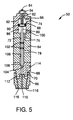
- Fig. 5 is a cross-sectional view of a nozzle;
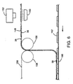
- Fig. 6 is a schematic diagram illustrating subsequent handling of a sprayed surface;
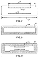
- Figs. 7 and 8 are top plan views of a sprayed portion of a moving surface of in accordance with the method of the present invention.
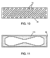
- Figs. 9-11 are similar to Figs. 7 and 8 illustrating other spray patterns; in accordance with the method of the present invention.
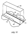
- Fig. 12 is an exploded, perspective view of a two-layered composite.
-
- Within the context of this specification, each term or phrase below will include the following meaning or meanings:
- (a) "Disposed" and variations or uses thereof are intended to mean that one element can be integral with another element, or that one element can be a separate structure joined to or connected or placed with or placed near another element.
- (b) "Pattern" includes any geometric or non-geometric form that can include, among others, a series of connected or unconnected lines or curves, a series of parallel or non-parallel or intersecting lines or curves, a series of linear or curvilinear lines, or any combinations thereof. The pattern can include a repeating form(s) and/or non-repeating form(s).
- (c) "Spray" and variations thereof includes forcefully ejecting liquid, either as a stream, such as swirl filaments, or atomized droplets through an orifice, nozzle, or the like, by means of an applied pressure of air or other gas, by force of gravity, or by centrifugal force. The spraying can he continuous or non-continuous.
- (d) "Liquid" includes a adhesive substance and/or material that flows and can assume the interior shape of a container into which it is poured or placed.
- (e)"Surface" includes any layer, paper, woven, non-woven, substrate, laminate, composite, or combinations thereof, and can be pervious or impervious.
- (f) "Reference" includes structure such as waist or leg elastics, adhesive material, comers or edges of structure, transporting medium such as conveyor belts, visual marks, magnetic marks, color marks, water-based marks, or other marks that can be sensed or measured.
- (g) "Connected" includes joining, either directly or indirectly, at least two elements together by mechanical means, electro-mechanical means, optico-electrical means, or any combinations thereof.
-
- Referring to Figs. 1 and 2, there is illustrated
apparatus 20 which may be operated according to the principles of the present invention.Apparatus 20 includesprogrammable control center 22 operatively connected toflow control system 24 which controls the delivery of a liquid, such as a hot melt adhesive in liquid form at application, to be sprayed; andposition sensing system 26, which is operatively connected toprogrammable control center 22, that senses the results or pattern of the spray of liquid and in response thereto generates a signal that is sent toprogrammable control center 22 for processing. The spray of liquid, which will be referred to as an adhesive spray, can be sprayed in a desired pattern on a moving surface as explained hereafter. -
Conveyor system 28 is spaced apart fromflow control system 24, and includes conveyor belt 30 (Fig. 1) having aconveyor belt surface 34 that moves continuously by means of conveyor roller 32, and chill roll 29 (Fig. 2) that conveysfilm 36 at a spaced-apart distance H fromflow control system 24. Here, distance H is 1.905cm (3/4 inch).Film 36, on which the adhesive is to be sprayed, is carried byconveyor belt surface 34 toflow control system 24.Film 36 can include any type of layer or web of material, such as films of thermoplastic material, a non-woven web of thermoplastic material or a combination of thermoplastic material and natural fibers such as wood pulp fluff fibers, woven webs made of strands of thermoplastic material, natural material such as threads of cotton and the like, or combinations thereof. Althoughreference numeral 36 will be referred to as a film, the present invention contemplates thatreference numeral 36 can include any of these types of layers or webs in the definition of the word "surface". As will be described hereafter in more specific terms,film 36 has the adhesive sprayed on its surface in a specific design or pattern for subsequent placement or joining to another surface. - Before
film 36 is conveyed to flowcontrol system 24, it has a plurality ofreferences 38 provided that can be sensed byposition sensing system 26. As earlier described, these references include some type of mark, signal, or location that can be sensed, measured, or the like, and in response thereto a signal can be generated byposition sensing system 26. In this description, the reference is a plurality of waist elastics 38 that are disposed onfilm 36 in any suitable manner. One manner of disposing waist elastics 38 is disclosed in U.S. Pat. No. 4,608,115 which issued August 26,1986, to the assignee of this application and is entitled "Revolving Transfer Roll". U.S. Pat. No. 4,608,115 is incorporated by reference herein. Other apparatus can be used to treatfilm 36 with other references, such as with different colors, magnetic marks, and the like. - In order to initiate the spray operation at the correct time or correct position,
timing mechanism 42 is mechanically coupled to conveyor roller 32 such as, for example, by a belt and pulley assembly represented by line orshaft 40, and operatively connected toprogrammable control center 22 byline 44.Timing mechanism 42 is aresolver 42, the lunction of which is to translate one revolution of conveyor roller 32 into one product length L and in response thereto generate an electrical signal toprogrammable control center 22 vialine 44. Product length L is the distance between a centerline of one pair ofelastics 38 and a centerline of a second pair ofelastics 38 as illustrated in Fig. 1.Resolver 42 is a rotary position transducer that is connected to conveyor roller 32, and produces a position signal that is converted to a digital format for processing byprogrammable control center 22. One type ofresolver 42 can be obtained from Namco Controls of Mentor, Ohio, and has part number CA 150-20000.Resolver 42 can be adjusted such that one rotation of conveyor roller 32 can be any fraction or multiple of a product length L. For example, one rotation of conveyor roller 32 can be translated into one-half a product length or twice a product length, and similarly one-half rotation of conveyor roller 32 can be translated into any fraction or multiple of product lengths L. Line orshaft 40 can also be connected to the apparatus disclosed in the above-mentioned U.S. Pat. No. 4,608,115 which can disposewaist elastics 38 onfilm 36. Thus, a pair of waist elastics 38 being positioned onfilm 36 can signalresolver 42 that a product length has been initiated or started, which in turn is processed byresolver 42 into a signal and sent throughline 44 toprogrammable center 22. As mentioned above, in any one product length L, the second waist elastic of one pair ofelastics 38 in the downstream direction, which is illustrated byarrow 46, and the first elastic in a subsequent pair of waist elastics 38, form the two waist elastics 38 for that one particular product length L. Other mechanisms may be adapted to be used betweenfilm 36 andprogrammable control center 22 to provide the desired signal toprogrammable center 22 to begin the spray operation. - Referring to Figs. 1-5,
flow control system 24 includes bank 48 (Fig. 4) of elevennozzles 50. The nozzles are in two rows, with sixnozzles 50 inrow 52 and fivenozzles 50 inrow 54, in which the two rows of nozzles overlap. In other words, a pair ofadjacent nozzles 50 in row 52 (Fig. 4) has theirsprays 56 overlapping aspray 56 of anozzle 50 inrow 54, as illustrated in Fig. 3. By offsettingnozzles 50 ofrow 54 withnozzles 50 ofrow 52, an uninterrupted spray of liquid can be directed ontofilm 36. As mentioned earlier, the sprayed liquid is a hot melt adhesive, but the invention contemplates that the liquid can be, different types of adhesive melts, or any other adhesive to be sprayed. - Each
nozzle 50 is connected to its ownrespective solenoid 58 which controls the flow of adhesive to and from that nozzle.Nozzle 50 can be any nozzle suitable for operation with the present invention; one such nozzle is obtainable from ITW Dynatec Co. of Hendersonville, Tennessee, and has part number 057B1639, I.D. #A3. - Each
solenoid 58 can be any solenoid suitable for operation with the invention; one such solenoid is obtainable from MAC Valves, Inc. of Luixom, Michigan, and has model No. 45AL00DDAJ1KG. - With reference to Figs. 1, 2, and 5, each
nozzle 50 is connected directly to itsown source 60 of adhesive and itsown source 62 of hot air for spraying and/or swirling the adhesive. Eachnozzle 50 includes amain body 64 andcap 66 threadedly joined together by respective threadedsurface 68 and threadedsurface 70.Body 64 includes amain passage 72 being in fluid communication withair port 74,air port 76, andadhesive inlet 78. - Movably disposed in
main passage 72 ispin 80, anddisk 88 that is sealed against the inner surface 96 bycircular seal 90. Stop-bolt 84 hasnut 94 threadedly engaged thereto for adjusting the movement ofpin 80 between a closed and stop position inpassage 72.Spring 92 is positioned betweennut 94 anddisk 88 to urgedisk 88 downwardly as viewed in Fig. 5.Disk 88 is located betweenair port 74 andair port 76, andspring 92 urgespin 80 in a downward direction as viewed in Fig. 5. A pair ofseals 102 are disposed betweenpin 80 andmain passage 72 belowdisk 88, and the series ofseals chamber 98 in fluid communication withair port 74, andchamber 100 in fluid communication withair port 76.Chambers seal 90. - The lowermost portion of
pin 80 includes taperedend 104 that sealingly fits cone-shapedsection 106 ofmain passage 72.Tapered end 104 is illustrated in the open position, and whenpin 80 is moved downwardly to seat against cone-shapedsection 106,main passage 72 is closed. Betweenseals 102 and cone-shapedsection 106 isadhesive chamber 108 in fluid communication withadhesive inlet 78. Below cone-shapedsection 106,main passage 72 continues downwardly towardadhesive opening 110 incap 66.Cap 66 andmain body 64 form therebetweenhot air chamber 112 which is in fluid communication withhot air inlet 114 inmain body 64 andhot air openings 116. - Referring primarily to Figs. 1 and 2, each
solenoid 58 is a three-way valve that is operable between an air-inlet position, an air-outlet position, and an exhaust position in which air flow is exhausted to vacate pressure atair ports solenoid 58 is connected to anozzle 50 byair line 118 in fluid communication withair port 74 ofnozzle 50, andair line 120 in fluid communication withair port 76 in nozzle 50 (Fig. 5).Air manifold 122 delivers air under pressure to arespective solenoid 58.Air manifold 122 can be supplied with air under pressure by any suitable means, such as by a gear pump. - Adhesive is supplied from a respective source 60 (Fig. 1) to a respective adhesive pump 124 (Fig. 2), which is a obtainable from Acumeter Laboratories of Marlborough, Massachusetts, and has a pump assembly No.16269.
- The flow of adhesive to
adhesive pump 124 can be supplied by any suitable means, such as by a gear pump. Eachadhesive pump 124 is connected to an adhesive inlet 78 (Fig. 5) of anozzle 50 by anadhesive supply line 126 and delivers adhesive to itsrespective nozzle 50 at a constant pressure that is independent of and unaffected by the operation of the otheradhesive pumps 124 that deliver adhesive to theirrespective nozzles 50. Eachpump 124 and itsrespective nozzle 50 includes a pressure-relief chamber 128 that is closed off fromadhesive supply line 126 by aspring element 130. When arespective nozzle 50 is in the closed position, adhesive pressure builds up inadhesive supply line 126 until the force of arespective spring element 130 is overcome, thereby opening tank return line 132 (Fig. 2) which delivers the adhesive back to source 60 (Fig. 1). Dedicated to eachnozzle 50 is asolenoid 58,adhesive source 60,adhesive pump 124,tank return line 132, andsource 62 of hot air (Fig. 1). -
Source 62 of air can be supplied by any suitable means, such as by a gear pump, and is delivered by hotair supply line 134 to hot air inlet 114 (Fig. 5) innozzle 50. Aheater cartridge 136 is provided to eachnozzle 50 in order to provide heat to the adhesive to increase its flow properties. One such heater cartridge is obtainable from Watlow Electric Manufacturing Company of St. Louis, Missouri, and has a part number L7A37-NC12. - With reference to Fig. 1,
programmable control center 22 includescomputer 138,programmable limit switch 142, andinterface 140, such as an RS232 interface, operatively connectingcomputer 138 andprogrammable limit switch 142.Computer 138 further includesmanual control 144 for manually controllingprogrammable limit switch 142.Computer 138 receives position signals from position-sensingsystem 26 vialine 146.Computer 138 is a programmable computer, and one such computer is obtainable from Allen-Bradley of Milwaukee, Wisconsin, and is identified as a PLC 5/25 programmable logic controller.Computer 138 is programmed to receive a position signal from position-sensingsystem 26 and to determine whether an adhesive spray pattern, either the whole pattern itself or only a portion thereof, is correctly positioned onfilm 36 with reference to waist elastic 38. If the position of the spray pattern does not meet the criteria of the programmed instruction incomputer 138,computer 138 will generate a correction signal in response to the adhesive pattern being out of position, and send the correction signal to interface 140. -
Interface 140 encodes the correction signal fromcomputer 138 and sends it toprogrammable limit switch 142, which in turn receives the correction signal and adjusts the operation of any one or more ofnozzles 50 to properly position a subsequent adhesive spray pattern onfilm 36 with reference to waist elastic 38. One such programmable limit switch is obtainable from Namco Controls, an Acme-Cleveland Company, of Mentor, Ohio, and is identified as C&A Programmable Limit Switch No. CA410-23000. -
Programmable limit switch 142 will select which nozzles 50 that should be actuated to spray earlier in time or later in time, and also determines whether the duration of spray time should be increased or decreased. - In response to the control signals from
programmable limit switch 142,nozzles 50 spray a liquid in a desired pattern 148 (Fig. 1) onfilm 36. Asfilm 36 moves in the direction ofarrow 46, it approaches position-sensingsystem 26, which includescamera system module 154,camera 152, and ultravioletlight source 150 disposed on an opposite side offilm 36 for radiating ultraviolet light againstfilm 36, waist elastics 38, andadhesive patterns 148. A detector such ascamera 152 optically senses the position of anadhesive pattern 148 relative towaist elastics 38. For example,camera 152 will optically sense the distance L1, which is the distance between a waist elastic 38 nearest to endedge 147 ofadhesive pattern 148, and the distance L2, which is the distance between opposite end edge 149 ofadhesive pattem 148 and the nearest waist elastic 38. The present invention contemplates other types of reference points that can be used to determine the position ofadhesive pattern 148 relative to waist elastic 38, and as mentioned earlier there are other types of references other than waist elastics 38 that can be used to measure or sense the position ofadhesive pattern 148 relative to its prescribed location onfilm 36.Camera system module 154 receives a signal fromcamera 152, generates a position signal in response thereto, and sends it vialine 146 tocomputer 138.Computer 138 then processes that position signal and, whenadhesive pattern 148 is out of position, generates and sends a correction signal to interface 140, which encodes the signal and sends it toprogrammable limit switch 142. One such position sensing system is obtainable from the Videk System Division of Eastman Technology, Inc. located in Canadaigua, New York; in whichcamera system module 154 is identified as model No. RM 1000E,camera 152 is identified as model No. K01313, andlight source 150 is identified as model No. K01289. - In the above description, waist elastics 38, which serve as the references for detecting the position of
adhesive pattern 148, have been described as being positioned onfilm 36 beforeflow control system 24 sprays adhesive onfilm 36. The present invention contemplates that this sequence can be reversed such thatflow control system 24 first sprays the desiredadhesive pattern 148, and thereafter waist elastics 38 are disposed onfilm 36 relative toadhesive pattern 148. Then, the sensing of the position ofadhesive pattern 148 onfilm 36 relative to the references can be the same as described above. - In operation,
conveyor system 28 is operated and waist elastics 38 are disposed onfilm 36, line orshaft 40 begins to operate, andresolver 42 signalsprogrammable limit switch 142 ofprogrammable control center 22 vialine 44, as illustrated in Fig. 1.Programmable limit switch 142, which has been preprogrammed with an instruction for eachnozzle 50 inbank 48, begins to operate eachnozzle 50 to open the nozzle at a preprogrammed time or position to applyspray 56 at a prescribed location onfilm 36, maintains eachnozzle 50 in the open position for a preprogrammed duration of time. and then closes eachnozzle 50 at a preprogrammed time. - Since each
nozzle 50 operates the same, a description of the operation of onenozzle 50 only will be given. With reference to Figs. 1, 2 and 5, apump 124 for arespective nozzle 50 is continuously running to supply adhesive from a source 60 (Fig. 1) via adhesive supply line 126 (Fig. 2) to adhesive inlet 78 (Fig. 5). Similarly, asource 62 is continuously providing air via air line 134 (Fig. 2) to hot air inlet 114 (Fig. 5),hot air chamber 112 and throughhot air openings 116. As mentioned earlier, eachsolenoid 58 is a three-position or three-way valve operating to deliver, from air manifold 122 (Fig. 2), a supply of air to either air port 74 (Fig. 5) orair port 76, or to be positioned at an exhaust position. With asolenoid valve 58 in the closed position, spring 92 (Fig. 5)biases pin 80 downwardly to seat taperedend 104 in cone-shapedsection 106 to prevent any flow of adhesive fromadhesive inlet 78 andadhesive chamber 108 throughadhesive opening 110.Solenoid 58 is activated by a signal fromprogrammable limit switch 142 to opennozzle 50 by supplying air fromair manifold 122 toair port 76 in order to create pressure inchamber 100 greater than the pressure inchamber 98 so as to movedisk 88 andpin 80 upwardly to unseattaper end 104, thereby permitting adhesive to flow under pressure throughadhesive inlet 78,adhesive chamber 108, and throughadhesive opening 110 in aspray 56 on film 36 (Fig. 1). As illustrated in Fig. 2,film 36 is delivered byconveyor belt surface 34 overchill roll 29 which is chilled so that the hot adhesive does not melt the film. Heater cartridge 136 (Fig. 2) serves to maintain the adhesive at the proper temperature to maintain it in a state sufficient for spraying. -
Programmable limit switch 142, after opening anozzle 50, is programmed to maintain thatnozzle 50 in the open position for a specified period of time at the end of whichprogrammable limit switch 142 activatessolenoid 58 to stop the flow of air to airport 76 and to begin a flow of air to airport 74 andchamber 98; this, together withspring 92, movesdisk 88 andpin 80 in a downward direction to seat taperedend 104 in cone-shapedsection 106, thereby stopping the flow of adhesive throughadhesive opening 110. Thereafter, the build-up of adhesive pressure activatesspring element 130 in pressure-relief chamber 128 to permit adhesive to flow throughtank return line 132 to asource 60. -
Programmable limit switch 142 operates each of thenozzles 50 at a preprogrammed time and for a preprogrammed duration that results inadhesive pattern 148, which as illustrated in Fig. 1 is a generally rectangular adhesive pattern which is not in accordance with the method of the present invention. Asfilm 36 withadhesive pattern 148 and waist elastics 38 moves in the direction ofarrow 46, position-sensingsystem 26 activates UVlight source 150 andcamera 152 to optically sense the position ofadhesive pattern 148 relative towaist elastics 38. As described earlier, the position can be measured by length L1 and length L2 (Fig. 1), which are the respective distances between thedownstream end edge 147 ofadhesive pattern 148 and the nearest adjacent waist elastic 38 and the distance between the upstream end edge 149 of the sameadhesive pattern 148 and the nearest adjacent waist elastic 38.Camera 152 sands that measured information tocamera system 154 which generates and sends a position signal tocomputer 138 vialine 146.Computer 138, which has been preprogrammed as desired for the specific operation and adhesive pattern design, determines ifadhesive pattern 148 is out of position, which may be due to any of several reasons such as the stretching or skewing offilm 36, and, if out of position, processes that information according to preprogrammed instructions to generate and send a correction signal toprogrammable limit switch 142 viainterface 140.Programmable limit switch 142 receives the correction signal, which may apply to one or more ofnozzles 50, and will controllably adjust the operation of thenecessary nozzles 50 to begin the spray operation earlier or later and/or to stop the spray operation earlier or later. - Because each
nozzle 50 has itsown control solenoid 58, itsown source 60 of pressurized adhesive, and its own pressurized source ofhot air 62, eachnozzle 50 can be quickly operated independently of theother nozzles 50 to provide nearly instantaneous initiation and termination of a spray of adhesive or other liquid. Further-more, because eachnozzle 50 has its own supplies of adhesive and hot air, and is individually controlled byprogrammable limit switch 142, the turning on or off of more or fewer nozzles does not affect the pressure of the adhesive delivered through other operatingnozzles 50, which maintains the mass flow rate of adhesive through anozzle 50 constant, thereby not affecting aspray 56 and anadhesive pattern 148 made bysprays 56. - Although the invention has been described as spraying adhesive, other combinations of spray operations can be utilized by the present invention. For example.
certain nozzles 50 can have one type of adhesive, while other nozzles have a different type of adhesive. If other types and combinations of adhesive are to be used, different types ofnozzles 50 may be needed to accommodate the different adhesives. There also may be a requirement to adjust distance H (Fig. 2) and the flow of hot air from sources 62 (Fig. 1). -
Adhesive pattern 148 can be moved, as viewed in Fig. 1, to the felt or to the right, up or down, or lengthened or narrowed, or any combination thereof, by programmingprogrammable limit switch 142 andcomputer 138 with appropriate instructions. Similarly,adhesive pattern 148 can have its design changed, for example, from a rectangular design to an hourglass design, or from a design of non-continuous to continuous lines, or any combinations as earlier described. - After
adhesive pattern 148 has been applied tofilm 36, subsequent handling offilm 36, as one example, is illustrated in Fig. 6.Film 36 is adhesively contacted with a second layer, such asnonwoven layer 156, between nip rolls 158 to compressadhesive pattern 148 againstnonwoven layer 156. Thereafter, this two-layered composite is positioned on, for example, liquid-permeable liner 160 that has a plurality ofabsorbents 162 thereon.Absorbents 162 can be all fluff, a blend of fluff and superabsorbent materials, synthetic fibers, or any combinations thereof, and is wrapped in a tissue wrap (not shown) to maintain the integrity of the absorbent material. Thereafter, multiple products can be cut from this continuously moving line in order to form individual absorbent articles having a liquid-permeable liner 160, an absorbent 162, a liquid-impermeable film 36, and a cloth-likenonwoven layer 156. This type of general structure can be used in any number of personal care articles, such as a child's training pant or a baby diaper. A description of two types of child's training pants are disclosed in U.S. Pat. No. 4,940,464, issued July 10, 1990, to the assignee of the present invention, and EP No. 92121010 (USSN 071809,953), filed December 18, 1991, assigned to the assignee of the present invention; the contents of both being incorporated by reference herein. One design of a baby diaper is disclosed in EP No: 92115530 (USSN 07/757,760), filed September 11, 1991, and assigned to the assignee of the present invention; the contents of which are incorporated by reference herein. - As mentioned earlier, the adhesive, can be sprayed in any number of desired patterns by appropriately programming the present invention. Fig. 7 illustrates a pattern not in accordance with the method of the present invention, in which
film 36 has a pair of generally parallel, spaced-apartadhesive lines computer 138 andprogrammable limit switch 142 to open andclose nozzles 50 as desired. For the design in Fig. 7, the outwardlymost nozzles 50 ofrow 52 or row 54 (Fig. 4) are opened and closed at preprogrammed times to spray thestraight lines - Fig. 8 illustrates a rectangular
adhesive pattern 168 which is also not in accordance with the method of the present invention onfilm 36, The width or narrowness of the application of adhesive can be varied by adjusting the height H (Fig. 2), by varying the number ofhot air openings 116, varying theadhesive opening 110, varying nozzle type or other combinations. - If desired or necessary. the supply of hot air from any operation of the present invention may be eliminated.
- Fig. 9 illustrates
adhesive pattern 170 in accordance with the method of the present invention onfilm 36 that is generally hourglass shaped in whichmultiple nozzles 50 have been rapidly tumed on and off by a preprogrammed instruction in order to provide a stair-step composite spray pattern of liquid that defines the hourglass shape. - Fig. 10 illustrates yet another adhesive pattern 172 in accoirdance with the method of the present invention that has rows of adhesive that are generally parallel, spaced apart, stair-stepped, and at an angle with the longitudinal centerline of
film 36. - Fig. 11 illustrates yet another
adhesive pattem 174 in accordance with the method of the present invention. - Although not illustrated,
nozzles 50 can be operated to fully coverfilm 36 with adhesive material. - Fig. 12 illustrates joining together two different layers, such as for example, a liquid-
permeable liner 176 with a pair of spaced-apart waste containment flaps 178, andlayer 182. Twoadhesive lines 180 have been sprayed onliner 176 in a pattern not in accordance with the method of the present invention. Thereafter, the morenarrow layer 182 is positioned on top ofadhesive lines 180 to joinlayer 182 toliner 176.
Claims (18)
- A method of spraying a liquid in a plurality of patterns on a moving surface, comprising the steps of:wherein the plurality of nozzles are opened and closed at preprogrammed times to provide a stair-stepped pattern (170; 172) on the surface (36);moving the surface (36);supplying a plurality of sources of liquid (60);providing a plurality of nozzles (50) in fluid communication with respective ones of the plurality of sources of liquid (60) such that each nozzle has its own respective source of liquid;individually controlling each nozzle (50) independently of the other nozzles to spray the liquid at the moving surface (36) to form a pattern on the moving surface (36);
characterized in that the liquid is an adhesive, and in that each source (60) of liquid supplies adhesive to a respective adhesive pump (124) which delivers adhesive to a respective nozzle (50) at a pressure that is independent of and unaffected by the operation of the other adhesive pumps (124) that deliver adhesive to their respective nozzles (50). - The method of claim 1 wherein the step of individually controlling includes forming a plurality of patterns on the moving surface (36).
- The method of claim 1 or 2 wherein the step of moving includes disposing a plurality of references (38) on the moving surface (36), and
wherein the step of individually controlling further includes forming the plurality of patterns relative to the plurality of references. - The method of claim 3, further comprising the steps of:sensing the position of a pattern relative to its respective reference,generating a position signal in response to the sensed position of the pattern relative to its respective reference,processing the position signal according to a preprogrammed instruction,generating a correction signal when the pattern is out of position relative to its reference, andadjusting the control of selected ones of the spray devices to correctly position a subsequent pattern relative to its reference.
- The method of claim 4 wherein the step of individually controlling includes moving a pattern relative to its reference.
- The method of claim 4 or 5 wherein the step of individually controlling includes changing a pattern.
- The method of any one of the preceding claims wherein the step of supplying includes supplying at least one source with a liquid different from the other sources.
- An apparatus (20) for spraying a liquid in a pattern on a surface, for carrying out the method of any one of the preceding claims, comprising:characterized in that the liquid is an adhesive, and in that each source (60) of liquid supplies adhesive to a respective adhesive pump (124) connected to an adhesive inlet (78) of a respective nozzle (50) by an adhesive supply line (126) and which in use delivers adhesive to a respective nozzle (50) at a pressure that is independent of and unaffected by the operation of the other adhesive pumps (124) that deliver adhesive to their respective nozzles (50).a conveyor means (26) including a continuously moving platform adapted for continuously moving a surface (36);a plurality of nozzles (50) being in spaced-apart relationship to said moving platform, each said nozzle being controllable between an open position and a closed position, whereby each said nozzle (50) when in said open position is adapted to spray a delivered liquid on the surface (36) and when in said closed position is adapted to stop the spray (56) of liquid;a plurality of liquid sources (60) being in fluid communication with respective ones of said plurality of nozzles (50) such that each nozzle has its own liquid source, whereby each said liquid source (60) is adapted to deliver a flow of liquid to a respective said nozzle (50);a programmable control means (22) being connected to said plurality of nozzles (50) for individually controlling each said nozzle (50) independently of the others said nozzles between said open position and said closed position, whereby the delivered liquid is sprayed in a stair-stepped pattern (170; 172) on the surface (36);
- The apparatus of claim 8 wherein the surface has a reference (38) thereon, further comprising:wherein said programmable control means (22) processes the position signal according to a preprogrammed instruction and, when the pattern is out of position relative to the reference, individually controls said nozzles (50) to adjust a position of a subsequent pattern relative to its reference.a sensing means (26) connected to said programmable control means (22) and adapted for sensing a position of the pattern (38) relative to the reference and for sending a position signal to said programmable control means (22) in response to the position of the pattern relative to the reference, and
- The apparatus of claim 8 or 9 further comprising a timing means (42) being connected between said conveyor means (28) and said programmable control means (22) for sensing the operation of said conveyor means (28) and in response thereto for generating an operation signal to said programmable control means (22), and
wherein said programmable control means (22) processes said operation signal according to a pre-programmed instruction and in response thereto individually controls said nozzles (50). - The apparatus of any one of claims 8 to 10, further comprising:a solenoid member (58) being connected between said nozzle (50) and said programmable control means (22), whereby said solenoid member (58) controls said nozzle (50) between said open position and said closed position in response to signals from said programmable control means (22).
- The apparatus of any one of claims 8 to 11 wherein said programmable control means (22) comprises:a computer means (138) for receiving and processing input signals and for generating and sending output signals according to a preprogrammed instruction, anda limit switch means (142) being connected between said computer means (138) and said nozzles (50) for receiving said output signals from said computer means (138) and in response thereto for individually controlling each said nozzle (50) independently of the other said nozzles between said open position and said closed position.
- The apparatus of claim 12 wherein said limit switch means (142) is a programmable limit switch.
- The apparatus of claim 13 wherein said programmable limit switch (142) is programmable to selectively vary the control of each said nozzle, whereby patterns of sprayed liquid on the surface can be selectively varied.
- The apparatus of any one of claims 8 to 14 further comprising a heating means provided to each said nozzle for heating the liquid prior to being sprayed.
- Use of the method of any one of claims 1 to 7 or the apparatus of any one of claims 8 to 15 for joining together a layer and an absorbent disposed with said layer of a disposable absorbent article.
- Use of the method of any one of claims 1 to 7 or the apparatus of any one of claims 8 to 15 for joining together a base sheet and an absorbent being positioned with said base sheet, of an absorbent article.
- Use of the method of any one of claims 1 to 7 or the apparatus of any one of claims 8 to 15 for joining in a disposable absorbent article comprising:a topsheet, a backsheet, an absorbent being positioned between said topsheet and backsheet a layer to said topsheet.
Priority Applications (2)
| Application Number | Priority Date | Filing Date | Title |
|---|---|---|---|
| EP98100480A EP0843037B1 (en) | 1992-12-16 | 1993-12-16 | Methods and apparatus for controlling a spray of liquid to form a pattern |
| DE9321518U DE9321518U1 (en) | 1992-12-16 | 1993-12-16 | Selective control of a liquid spray to form a characteristic pattern and disposable absorbent articles using them |
Applications Claiming Priority (2)
| Application Number | Priority Date | Filing Date | Title |
|---|---|---|---|
| US99178092A | 1992-12-16 | 1992-12-16 | |
| US991780 | 1992-12-16 |
Related Child Applications (1)
| Application Number | Title | Priority Date | Filing Date |
|---|---|---|---|
| EP98100480A Division EP0843037B1 (en) | 1992-12-16 | 1993-12-16 | Methods and apparatus for controlling a spray of liquid to form a pattern |
Publications (3)
| Publication Number | Publication Date |
|---|---|
| EP0603748A1 EP0603748A1 (en) | 1994-06-29 |
| EP0603748B1 EP0603748B1 (en) | 1998-07-29 |
| EP0603748B2 true EP0603748B2 (en) | 2003-01-02 |
Family
ID=25537554
Family Applications (2)
| Application Number | Title | Priority Date | Filing Date |
|---|---|---|---|
| EP93120315A Expired - Lifetime EP0603748B2 (en) | 1992-12-16 | 1993-12-16 | Methods and apparatus for selectively controlling a spray of liquid to FORM a distinct pattern and use of the method for the fabrication of a disposable absorbent article |
| EP98100480A Expired - Lifetime EP0843037B1 (en) | 1992-12-16 | 1993-12-16 | Methods and apparatus for controlling a spray of liquid to form a pattern |
Family Applications After (1)
| Application Number | Title | Priority Date | Filing Date |
|---|---|---|---|
| EP98100480A Expired - Lifetime EP0843037B1 (en) | 1992-12-16 | 1993-12-16 | Methods and apparatus for controlling a spray of liquid to form a pattern |
Country Status (11)
| Country | Link |
|---|---|
| US (1) | US5683752A (en) |
| EP (2) | EP0603748B2 (en) |
| JP (1) | JP3790275B2 (en) |
| KR (1) | KR100244420B1 (en) |
| AU (1) | AU668420B2 (en) |
| CA (1) | CA2095555A1 (en) |
| DE (2) | DE69320011T3 (en) |
| ES (2) | ES2118882T5 (en) |
| HK (1) | HK1013118A1 (en) |
| MX (1) | MX9307167A (en) |
| ZA (1) | ZA937749B (en) |
Families Citing this family (84)
| Publication number | Priority date | Publication date | Assignee | Title |
|---|---|---|---|---|
| US5801739A (en) * | 1995-04-12 | 1998-09-01 | Eastman Kodak Company | High speed digital fabric printer |
| AUPN233395A0 (en) * | 1995-04-12 | 1995-05-04 | Eastman Kodak Company | A high speed digital fabric printer |
| US6336921B1 (en) | 1995-05-31 | 2002-01-08 | Kimberly-Clark Worldwide, Inc. | Waist elastic system with improved elastic decay properties for a training pant |
| US6551430B1 (en) | 1995-05-31 | 2003-04-22 | Kimberly-Clark Worldwide, Inc. | Process for making a training pant having a unitary waist elastic system |
| US5601547A (en) * | 1995-05-31 | 1997-02-11 | Kimberly-Clark Corporation | Waist elastic system with improved modulus of elasticity for a child's training pant |
| US5711832A (en) * | 1995-05-31 | 1998-01-27 | Kimberly-Clark Worldwide, Inc. | Process for making a training pant having a separate waist elastic system |
| US6296463B1 (en) | 1998-04-20 | 2001-10-02 | Nordson Corporation | Segmented metering die for hot melt adhesives or other polymer melts |
| US6422428B1 (en) | 1998-04-20 | 2002-07-23 | Nordson Corporation | Segmented applicator for hot melt adhesives or other thermoplastic materials |
| US6344109B1 (en) | 1998-12-18 | 2002-02-05 | Bki Holding Corporation | Softened comminution pulp |
| US6299931B1 (en) * | 1999-04-09 | 2001-10-09 | W. H. Leary Co., Inc. | System and method for setting, regulating and monitoring an applicator |
| US6307119B1 (en) | 1999-06-15 | 2001-10-23 | Kimberly-Clark Worldwide, Inc. | Absorbent articles having wetness indicating graphics incorporating a training zone |
| US6596918B1 (en) | 2000-06-05 | 2003-07-22 | Kimberly-Clark Worldwide, Inc. | Absorbent articles having wetness indicating graphics and employing masking techniques |
| US6710221B1 (en) | 1999-06-15 | 2004-03-23 | Kimberly-Clark Worldwide, Inc. | Absorbent articles incorporating color change graphics |
| US6297424B1 (en) * | 1999-06-15 | 2001-10-02 | Kimberly-Clark Worldwide, Inc. | Absorbent articles having wetness indicating graphics providing an interactive training aid |
| US6379464B1 (en) | 1999-07-30 | 2002-04-30 | K-G Devices Corporation | Apparatus for applying material to a target in relative motion to a dispenser |
| US6506456B1 (en) * | 1999-10-29 | 2003-01-14 | Kimberly-Clark Worldwide, Inc. | Method for application of a fluid on a substrate formed as a film or web |
| DE10023673B4 (en) | 2000-05-16 | 2007-11-22 | Nordson Corp., Westlake | Distribution device for distributing fluids and device for dispensing and applying fluid, in particular adhesive |
| JP3712927B2 (en) * | 2000-09-04 | 2005-11-02 | 株式会社 日立インダストリイズ | Paste applicator |
| US20030082968A1 (en) * | 2000-09-28 | 2003-05-01 | Varunesh Sharma | Nonwoven materials having controlled chemical gradients |
| SE521383C2 (en) * | 2000-10-31 | 2003-10-28 | Nordson Corp | Apparatus and method for monitoring the operation of a fluid distributor gun |
| US6513897B2 (en) | 2000-12-29 | 2003-02-04 | 3M Innovative Properties Co. | Multiple resolution fluid applicator and method |
| US6467897B1 (en) | 2001-01-08 | 2002-10-22 | 3M Innovative Properties Company | Energy curable inks and other compositions incorporating surface modified, nanometer-sized particles |
| DE10139633C1 (en) * | 2001-08-11 | 2003-04-24 | Amtec Kistler Gmbh | Device for applying a coating agent |
| US6849130B2 (en) * | 2001-10-31 | 2005-02-01 | Nordson Corporation | Fluid dispenser with automatic compensation and method |
| US7306582B2 (en) * | 2001-12-19 | 2007-12-11 | The Procter & Gamble Company | Absorbent article |
| US7402157B2 (en) * | 2001-12-19 | 2008-07-22 | The Procter & Gamble Company | Absorbent article having perception of depth |
| US7270651B2 (en) * | 2001-12-19 | 2007-09-18 | The Procter & Gamble Company | Absorbent article |
| US7617951B2 (en) | 2002-01-28 | 2009-11-17 | Nordson Corporation | Compact heated air manifolds for adhesive application |
| US8716548B2 (en) | 2002-02-20 | 2014-05-06 | The Procter & Gamble Company | Disposable absorbent article designed to facilitate an easy change |
| US20030158532A1 (en) | 2002-02-20 | 2003-08-21 | Magee Luke R. | Disposable absorbent article designed to facilitate an easy intuitive change |
| KR100712088B1 (en) * | 2002-05-27 | 2007-05-02 | 한라공조주식회사 | Device and method for adhering friction material to clutch pulley |
| US8328780B2 (en) * | 2002-11-21 | 2012-12-11 | Kimberly-Clark Worldwide, Inc. | Absorbent article with elastomeric bordered material |
| US7294593B2 (en) * | 2002-11-21 | 2007-11-13 | Kimberly-Clark Worldwide, Inc. | Absorbent article material with elastomeric borders |
| US6814310B2 (en) * | 2002-11-26 | 2004-11-09 | Nordson Corporation | Metered liquid dispensing system |
| US20040224086A1 (en) * | 2003-05-05 | 2004-11-11 | Wright Ryan Erin | Automated hot melt application apparatus and method |
| US6811239B1 (en) | 2003-05-20 | 2004-11-02 | The Procter & Gamble Company | Method of inkjet printing in high efficiency production of hygienic articles |
| US7427424B2 (en) * | 2003-08-07 | 2008-09-23 | Hill David A | Systems and methods of bonding materials |
| US20050015050A1 (en) * | 2003-07-15 | 2005-01-20 | Kimberly-Clark Worldwide, Inc. | Apparatus for depositing fluid material onto a substrate |
| US7160281B2 (en) * | 2003-10-21 | 2007-01-09 | Kimberly-Clark Worldwide, Inc. | Absorbent article having an absorbent structure secured to a stretchable component of the article |
| US20050124961A1 (en) * | 2003-12-08 | 2005-06-09 | Kimberly-Clark Worldwide,Inc. | Absorbent article with elastomeric bordered extensible material bodyside liner and method of making |
| US20050124948A1 (en) * | 2003-12-08 | 2005-06-09 | Kimberly-Clark Worldwide, Inc. | Absorbent article with elastomeric bordered necked material bodyside liner and method of making |
| US7662745B2 (en) | 2003-12-18 | 2010-02-16 | Kimberly-Clark Corporation | Stretchable absorbent composites having high permeability |
| US7320814B2 (en) * | 2003-12-19 | 2008-01-22 | Kimberly-Clark Worldwide, Inc. | Methods for applying a liquid to a web |
| US8167861B2 (en) | 2003-12-31 | 2012-05-01 | Kimberly-Clark Worldwide, Inc. | Disposable garment with stretchable absorbent assembly |
| EP1591169A3 (en) * | 2004-04-29 | 2009-01-28 | Nordson Corporation | Automatic tolerance determination system for material application inspection operation |
| US20050242108A1 (en) | 2004-04-30 | 2005-11-03 | Nordson Corporation | Liquid dispenser having individualized process air control |
| US7993319B2 (en) | 2004-04-30 | 2011-08-09 | Kimberly-Clark Worldwide, Inc. | Absorbent article having an absorbent structure configured for improved donning of the article |
| US7462377B2 (en) * | 2004-04-30 | 2008-12-09 | Nordson Corporation | Methods for regulating the placement of fluid dispensed from an applicator onto a workpiece |
| US8246594B2 (en) | 2004-04-30 | 2012-08-21 | Kimberly-Clark Worldwide, Inc. | Absorbent article having an absorbent structure configured for improved donning and lateral stretch distribution |
| US7718844B2 (en) * | 2004-06-30 | 2010-05-18 | Kimberly-Clark Worldwide, Inc. | Absorbent article having an interior graphic |
| US7938813B2 (en) | 2004-06-30 | 2011-05-10 | Kimberly-Clark Worldwide, Inc. | Absorbent article having shaped absorbent core formed on a substrate |
| US7247215B2 (en) * | 2004-06-30 | 2007-07-24 | Kimberly-Clark Worldwide, Inc. | Method of making absorbent articles having shaped absorbent cores on a substrate |
| US7772456B2 (en) | 2004-06-30 | 2010-08-10 | Kimberly-Clark Worldwide, Inc. | Stretchable absorbent composite with low superaborbent shake-out |
| US20060005496A1 (en) * | 2004-07-12 | 2006-01-12 | Ridglass Manufacturing Company, Inc. | Torchless self-adhesive roofing product and method |
| US20060099871A1 (en) * | 2004-11-05 | 2006-05-11 | Kimberly-Clark Worldwide, Inc. | Reinforced elastic fiberous web |
| US7364775B2 (en) * | 2004-11-09 | 2008-04-29 | Nordson Corporation | Closed loop adhesive registration system |
| US8689689B2 (en) * | 2004-11-12 | 2014-04-08 | Spraying Systems Co. | System and method for marking sheet materials |
| US7208721B2 (en) * | 2004-11-22 | 2007-04-24 | Illinois Tool Works Inc. | Controller for material dispensing nozzle control signal and methods |
| US20060149208A1 (en) * | 2004-12-30 | 2006-07-06 | Kimberly-Clark Worldwide, Inc. | Absorbent article with elastomeric end regions |
| US20060144503A1 (en) * | 2004-12-30 | 2006-07-06 | Kimberly-Clark Worldwide, Inc. | Method of making absorbent articles with elastomeric end regions |
| GB0505873D0 (en) * | 2005-03-22 | 2005-04-27 | Ten Cate Advanced Textiles Bv | Method of depositing materials on a textile substrate |
| ES2559003T3 (en) * | 2006-01-06 | 2016-02-10 | Nordson Corporation | Liquid dispenser with individualized process air control |
| PL2111303T3 (en) * | 2007-01-26 | 2015-04-30 | Haas Mondomix B V | Device and method for dosing foamed compounds |
| US7736688B2 (en) | 2007-02-23 | 2010-06-15 | Procter & Gamble | Printed web and method for making |
| US8142876B2 (en) | 2007-02-23 | 2012-03-27 | The Procter & Gamble Company | Printed nonwoven web and method for making |
| US8575417B2 (en) | 2007-02-23 | 2013-11-05 | The Procter And Gamble Company | Printed formed film web and method for making |
| US8496775B2 (en) | 2010-10-28 | 2013-07-30 | The Procter And Gamble Company | Method for embossing an absorbent article |
| US8859842B2 (en) | 2010-10-28 | 2014-10-14 | The Procter & Gamble Company | Embossed absorbent article |
| US8491742B2 (en) | 2010-10-28 | 2013-07-23 | The Procter And Gamble Company | Method for embossing an absorbent article using a segmented anvil |
| DE102011103326B4 (en) * | 2011-05-27 | 2014-08-07 | Siempelkamp Maschinen- Und Anlagenbau Gmbh & Co. Kg | Apparatus and method for gluing fibers |
| US9682392B2 (en) | 2012-04-11 | 2017-06-20 | Nordson Corporation | Method for applying varying amounts or types of adhesive on an elastic strand |
| US9034425B2 (en) | 2012-04-11 | 2015-05-19 | Nordson Corporation | Method and apparatus for applying adhesive on an elastic strand in a personal disposable hygiene product |
| ITVR20120207A1 (en) * | 2012-10-18 | 2014-04-19 | Projecta Engineering S R L | DECORATION LINE FOR CERAMIC PRODUCTS |
| ITBO20120612A1 (en) * | 2012-11-07 | 2014-05-08 | Veneto Nanotech S C P A | PROCEDURE FOR THE TREATMENT OF A SUBSTRATE IN FIBER AND MACHINE TO IMPLEMENT THIS PROCEDURE. |
| US20160009438A1 (en) * | 2013-03-04 | 2016-01-14 | Golden Line | Linerless label device and method |
| US8852729B1 (en) | 2013-03-15 | 2014-10-07 | Davinci Engineering & Consulting, Llc | Seep resistant masking material |
| US20150057632A1 (en) | 2013-08-23 | 2015-02-26 | The Procter & Gamble Company | Absorbent Article |
| RU2636366C2 (en) * | 2013-09-16 | 2017-11-22 | Дзе Проктер Энд Гэмбл Компани | Absorbing products with channels and indicating elements |
| JP6170883B2 (en) * | 2014-06-26 | 2017-07-26 | 本田技研工業株式会社 | Method for producing hot melt adhesive |
| JP6132815B2 (en) * | 2014-06-27 | 2017-05-24 | 本田技研工業株式会社 | Method for producing hot melt adhesive |
| US9873132B2 (en) * | 2015-06-04 | 2018-01-23 | Lenovo Enterprise Solutions (Singapore) Pte. Ltd. | Digital processing equipment |
| JP6429830B2 (en) * | 2016-05-30 | 2018-11-28 | ユニ・チャーム株式会社 | Absorbent article manufacturing method and adhesive coating apparatus |
| FR3052086B1 (en) * | 2016-06-07 | 2018-06-15 | Louis Vuitton Malletier | SYSTEM FOR TESTING A FRAGRANCE |
| CN112452649B (en) * | 2020-11-09 | 2022-05-13 | 南京多脉智能设备有限公司 | Magnetic fluid profiling curved surface dispensing manipulator complete machine |
Citations (10)
| Publication number | Priority date | Publication date | Assignee | Title |
|---|---|---|---|---|
| US4157149A (en) † | 1977-10-31 | 1979-06-05 | Moen Lenard E | Multiple nozzle fluid dispenser for complex fluid delivery patterns |
| US4380967A (en) † | 1981-09-14 | 1983-04-26 | Nordson Corporation | System for automatically coating objects with a plurality of quantities of a coating material using a single discharge apparatus |
| US4528630A (en) † | 1982-09-14 | 1985-07-09 | Oao Corporation | Automatic registration control method and apparatus |
| US4725468A (en) † | 1986-02-06 | 1988-02-16 | Acumeter Laboratories, Inc. | Method of co-extrusion of different coating materials, including adhesive coating with intermittent non-adhering sections, and products produced thereby |
| US4764242A (en) † | 1986-12-18 | 1988-08-16 | The Kendall Company | Adhesive applying apparatus |
| EP0293065A2 (en) † | 1987-05-26 | 1988-11-30 | Acumeter Laboratories Inc. | Method and apparatus for depositing viscous fluids on a surface |
| US4792817A (en) † | 1983-08-29 | 1988-12-20 | Diagraph Corporation | Ink jet printing systems |
| US4874451A (en) † | 1986-03-20 | 1989-10-17 | Nordson Corporation | Method of forming a disposable diaper with continuous/intermittent rows of adhesive |
| CA2027855A1 (en) † | 1990-05-01 | 1991-11-02 | Steven Lambert Weyenberg | Apparatus and method for registration control of assembled components |
| DE3804856C2 (en) † | 1988-02-17 | 1992-07-30 | Macon Gmbh Klebstoff-Auftragsgeraete, 4006 Erkrath, De |
Family Cites Families (81)
| Publication number | Priority date | Publication date | Assignee | Title |
|---|---|---|---|---|
| US3219276A (en) * | 1962-10-16 | 1965-11-23 | Edward O Norris | Plural nozzles having intersecting spray and control therefor |
| US3402695A (en) * | 1966-10-24 | 1968-09-24 | Baker & Gubbins Co | Liquid applicator system |
| US3452710A (en) * | 1967-06-06 | 1969-07-01 | Baker & Gubbins Co | Liquid applicator system |
| US3584571A (en) * | 1967-08-25 | 1971-06-15 | Pannier Corp The | Character generation marking device |
| US3661679A (en) * | 1970-09-08 | 1972-05-09 | Lockwood Tech | Adhesive applicator for plywood patching machine |
| CA1058125A (en) * | 1974-07-25 | 1979-07-10 | Richard K. Teed | Apparatus for successively forming disposable diapers |
| US3952745A (en) * | 1974-11-19 | 1976-04-27 | The Procter & Gamble Company | Disposable diaper having readily flushable absorbent media and improved pad intergrity in use |
| US3965906A (en) * | 1975-02-24 | 1976-06-29 | Colgate-Palmolive Company | Absorbent article with pattern and method |
| US4069822A (en) * | 1975-10-30 | 1978-01-24 | The Procter & Gamble Company | Porous fibrous web to a substrate and articles therefrom |
| US4170883A (en) * | 1976-05-17 | 1979-10-16 | Milliken Research Corporation | Printing of pattern designs with computer controlled pattern dyeing device |
| US4058991A (en) * | 1976-11-29 | 1977-11-22 | Milliken Research Corporation | Dyeing machine |
| DE2700004A1 (en) * | 1977-01-03 | 1978-07-06 | Sick Optik Elektronik Erwin | ELECTRO-OPTICAL FOLDING MONITORING DEVICE |
| US4237539A (en) * | 1977-11-21 | 1980-12-02 | E. I. Du Pont De Nemours And Company | On-line web inspection system |
| BR7808292A (en) * | 1977-12-20 | 1979-08-07 | Johnson & Johnson | DISPOSABLE DIAPER |
| NZ190520A (en) * | 1978-05-29 | 1982-11-23 | Tybar Eng Pty Ltd | Patterned application of liquid to moving strip |
| US4211227A (en) * | 1978-07-03 | 1980-07-08 | The Kendall Company | Surgical sponge material |
| DE2938360A1 (en) * | 1978-09-28 | 1980-04-10 | Colgate Palmolive Co | SUCTIONABLE TEMPLATE |
| US4216774A (en) * | 1978-11-13 | 1980-08-12 | Alegra Products, Inc. | Medical pad |
| US4264957A (en) * | 1979-05-23 | 1981-04-28 | Zerand Corporation | Apparatus and method for register control in web processing apparatus |
| US4325372A (en) * | 1979-10-16 | 1982-04-20 | Riegel Textile Corporation | Elastic leg disposable diaper |
| US4239578A (en) * | 1979-10-16 | 1980-12-16 | Riegel Textile Corporation | Apparatus for inserting elastic strips during the manufacture of elastic leg disposable diapers |
| JPS56161870A (en) * | 1980-05-14 | 1981-12-12 | Sumitomo Light Metal Ind Ltd | Method and apparatus for coating long pipe having small diameter |
| US4309881A (en) * | 1980-04-21 | 1982-01-12 | Milliken Research Corporation | Apparatus for the application of liquids to moving materials |
| US4680205A (en) * | 1980-07-07 | 1987-07-14 | Automated Packaging Systems, Inc. | Continuous web registration |
| DE3265327D1 (en) * | 1981-02-24 | 1985-09-19 | Procter & Gamble | Disposable absorbent article having an improved liquid migration resistant perimeter construction |
| CA1175602A (en) * | 1981-07-17 | 1984-10-09 | Mohammed I. Aziz | Disposable absorbent article having elasticized flaps provided with leakage resistant portions |
| EP0079153B1 (en) * | 1981-10-30 | 1985-08-21 | Crosfield Electronics Limited | Controlling register in a printing press |
| US4643728A (en) * | 1981-12-07 | 1987-02-17 | Colgate Palmolive Company | Elasticized diaper with waterproof crotch seals |
| US4456374A (en) * | 1981-12-11 | 1984-06-26 | Johnson & Johnson | Detecting the presence or absence of a coating on a substrate |
| US4490618A (en) * | 1982-04-12 | 1984-12-25 | Canadian Patents & Development Limited | Optical system for analyzing the surface of a fibrous web |
| DE3242219C1 (en) * | 1982-11-15 | 1984-02-16 | Erwin Sick Gmbh Optik-Elektronik, 7808 Waldkirch | Optical brand recognition device |
| FI68320C (en) * | 1982-12-01 | 1985-08-12 | Valtion Teknillinen | FOERFARANDE Før by means of the ATT STRAOLNING FRAON A RADIOISOTOPKAELLA utan att FOERSTOERA sample was MAETA FOERDELNINGEN fyll audio-and / or BELAEGGNINGSMEDEL I TJOCKLEKSRIKTNINGEN audio PAPP ERARTONG or the like OCH Halten from these two MEDEL arranged RGAFOER TILLAEMPANDE audio FOERFARANDET SAMT ANVAENDNINGAR of devices for the AV ERFOARANDET OCH |
| FR2542979B1 (en) * | 1983-03-25 | 1988-04-22 | Boussac Saint Freres Bsf | PROCESS FOR THE CONTINUOUS MANUFACTURE OF DISPOSABLE PANTY LAYERS AND PANTY LAYERS OBTAINED |
| US4530862A (en) * | 1983-04-29 | 1985-07-23 | Spraymation, Inc. | Control system and method for dispensing a liquid |
| DE3325125C1 (en) * | 1983-07-12 | 1985-02-14 | Erwin Sick Gmbh Optik-Elektronik, 7808 Waldkirch | Arrangement for marking defects on fast moving material webs |
| CA1207104A (en) * | 1983-09-21 | 1986-07-08 | Reinhardt N. Sabee | Form fit diaper with inside seal and thickened crotch and method of making the same |
| DE3347160A1 (en) * | 1983-12-27 | 1985-08-29 | Türk & Hillinger GmbH, 7200 Tuttlingen | ELECTRIC HEATING DEVICE FOR PLASTIC INJECTION NOZZLES |
| US4685915A (en) * | 1984-04-06 | 1987-08-11 | The Procter & Gamble Company | Disposable diaper having density and basis weight profiled absorbent core |
| US4608115A (en) * | 1984-04-23 | 1986-08-26 | Kimberly-Clark Corporation | Revolving transfer roll |
| AU568944B2 (en) * | 1984-08-02 | 1988-01-14 | Johnson & Johnson | Diaper with facing raised above absorbent pad |
| US4719575A (en) * | 1984-09-14 | 1988-01-12 | Web Printing Control Co., Inc. | Method and apparatus for controlling web handling machinery |
| US4849768A (en) * | 1985-05-01 | 1989-07-18 | Burlington Industries, Inc. | Printing random patterns with fluid jets |
| US4797687A (en) * | 1985-05-01 | 1989-01-10 | Burlington Industries, Inc. | Patterning effects with fluid jet applicator |
| GB8517318D0 (en) * | 1985-07-09 | 1985-08-14 | Willett Int Ltd | Coding of absorbent materials |
| US4701239A (en) * | 1985-10-15 | 1987-10-20 | Paper Converting Machine Company | Applicator for applying two or more tapes to a moving web |
| GB2187419A (en) * | 1986-03-06 | 1987-09-09 | Dawson Ellis Ltd | Application of liquid to web or is sheet metal |
| US4687137A (en) * | 1986-03-20 | 1987-08-18 | Nordson Corporation | Continuous/intermittent adhesive dispensing apparatus |
| US4757930A (en) * | 1986-08-29 | 1988-07-19 | Adolph Coors Company | Web indicia reference signal generating system |
| JPS6397566A (en) * | 1986-10-13 | 1988-04-28 | Tokyo Kikai Seisakusho Ltd | Automatic adjuster for paper sheet cutting position in rotary press machine |
| US4764234A (en) * | 1986-12-18 | 1988-08-16 | The Kendall Company | Method of applying adhesive |
| US4795451A (en) * | 1986-12-18 | 1989-01-03 | The Kendall Company | Absorbent pad |
| US4711683A (en) * | 1987-03-09 | 1987-12-08 | Paper Converting Machine Company | Method and apparatus for making elastic diapers |
| US4778458A (en) * | 1987-04-16 | 1988-10-18 | Whitestone Products | Disposable sanitary absorbent incontinence pad |
| USRE33481E (en) * | 1987-04-23 | 1990-12-11 | Nordson Corporation | Adhesive spray gun and nozzle attachment |
| US4996091A (en) * | 1987-05-26 | 1991-02-26 | Acumeter Laboratories, Inc. | Product comprising substrate bearing continuous extruded fiber forming random crisscross pattern layer |
| US4815660A (en) * | 1987-06-16 | 1989-03-28 | Nordson Corporation | Method and apparatus for spraying hot melt adhesive elongated fibers in spiral patterns by two or more side-by-side spray devices |
| US4774109A (en) * | 1987-07-21 | 1988-09-27 | Nordson Corporation | Method and apparatus for applying narrow, closely spaced beads of viscous liquid to a substrate |
| EP0301431A1 (en) * | 1987-07-30 | 1989-02-01 | Peaudouce | Napkin with elastic bands extending longitudinally, and method for manufacturing this article |
| US4769650A (en) * | 1987-08-05 | 1988-09-06 | Industrial Technology Research Institute | Automatic ink-jet marking system |
| US4795510A (en) * | 1987-09-11 | 1989-01-03 | Kimberly-Clark Corporation | Process for applying reinforcing material to a diaper cover material |
| US4841307A (en) * | 1987-12-04 | 1989-06-20 | Burlington Industries, Inc. | Fluid jet applicator apparatus |
| JPH01162808A (en) * | 1987-12-19 | 1989-06-27 | Uni Charm Corp | Production of disposable diaper |
| US4983109A (en) * | 1988-01-14 | 1991-01-08 | Nordson Corporation | Spray head attachment for metering gear head |
| EP0329813A1 (en) * | 1988-02-26 | 1989-08-30 | Nordson Corporation | Valve arrangement for intermittently applying a liquid glue to a surface |
| US4911948A (en) * | 1988-09-07 | 1990-03-27 | Acumeter Laboratories, Inc. | Method of screen printing and application of hot melt upon moving web substrates |
| US4969602A (en) * | 1988-11-07 | 1990-11-13 | Nordson Corporation | Nozzle attachment for an adhesive dispensing device |
| DE8901172U1 (en) * | 1989-02-02 | 1990-06-07 | Nordson Corp., Westlake, Ohio, Us | |
| US4984169A (en) * | 1989-03-23 | 1991-01-08 | Milliken Research Corp. | Data loading and distributing process and apparatus for control of a patterning process |
| US5021051A (en) * | 1989-04-06 | 1991-06-04 | The Procter & Gamble Company | Disposable absorbent article having improved barrier leg cuffs |
| EP0395223A3 (en) * | 1989-04-24 | 1992-04-08 | American Colloid Company | Pouch for absorbing fluid |
| US5030303A (en) * | 1989-07-28 | 1991-07-09 | Nordson Corporation | Method for forming disposable garments with a waste containment pocket |
| GB8917790D0 (en) * | 1989-08-03 | 1989-09-20 | Smith & Nephew | Adhesive dressing |
| US5020723A (en) * | 1989-08-10 | 1991-06-04 | Crist Lawrence E | Hot melt glue spraying device |
| US4979380A (en) * | 1989-09-12 | 1990-12-25 | Sakowski And Robbins Corporation | Automated dye pattern application system |
| US4995333A (en) * | 1989-09-15 | 1991-02-26 | Kimberly-Clark Corporation | Sprayed adhesive system for applying a continuous filament of theroplastic material and imparting a swirling motion thereto |
| US5124111A (en) * | 1989-09-15 | 1992-06-23 | Kimberly-Clark Corporation | Method of forming a substantially continous swirled filament |
| US5088443A (en) * | 1989-10-04 | 1992-02-18 | Nordson Corporation | Method and apparatus for spraying a liquid coating containing supercritical fluid or liquified gas |
| US5033143A (en) * | 1990-02-20 | 1991-07-23 | Milliken Research Corporation | Method and apparatus for interrupting fluid streams |
| US5136520A (en) * | 1990-03-02 | 1992-08-04 | Milliken Research Corporation | System for assigning discrete time periods for dye applicators in a textile dyeing apparatus |
| US5065943A (en) * | 1990-09-06 | 1991-11-19 | Nordson Corporation | Nozzle cap for an adhesive dispenser |
| US5145689A (en) * | 1990-10-17 | 1992-09-08 | Exxon Chemical Patents Inc. | Meltblowing die |
-
1993
- 1993-05-05 CA CA002095555A patent/CA2095555A1/en not_active Abandoned
- 1993-06-25 JP JP15495593A patent/JP3790275B2/en not_active Expired - Fee Related
- 1993-10-19 ZA ZA937749A patent/ZA937749B/en unknown
- 1993-10-29 AU AU50373/93A patent/AU668420B2/en not_active Expired
- 1993-11-16 MX MX9307167A patent/MX9307167A/en unknown
- 1993-12-15 KR KR1019930027772A patent/KR100244420B1/en active IP Right Grant
- 1993-12-16 EP EP93120315A patent/EP0603748B2/en not_active Expired - Lifetime
- 1993-12-16 EP EP98100480A patent/EP0843037B1/en not_active Expired - Lifetime
- 1993-12-16 ES ES93120315T patent/ES2118882T5/en not_active Expired - Lifetime
- 1993-12-16 DE DE69320011T patent/DE69320011T3/en not_active Expired - Lifetime
- 1993-12-16 ES ES98100480T patent/ES2222529T3/en not_active Expired - Lifetime
- 1993-12-16 DE DE69333595T patent/DE69333595T2/en not_active Expired - Lifetime
-
1995
- 1995-05-17 US US08/442,923 patent/US5683752A/en not_active Expired - Lifetime
-
1998
- 1998-09-17 HK HK98110693A patent/HK1013118A1/en not_active IP Right Cessation
Patent Citations (10)
| Publication number | Priority date | Publication date | Assignee | Title |
|---|---|---|---|---|
| US4157149A (en) † | 1977-10-31 | 1979-06-05 | Moen Lenard E | Multiple nozzle fluid dispenser for complex fluid delivery patterns |
| US4380967A (en) † | 1981-09-14 | 1983-04-26 | Nordson Corporation | System for automatically coating objects with a plurality of quantities of a coating material using a single discharge apparatus |
| US4528630A (en) † | 1982-09-14 | 1985-07-09 | Oao Corporation | Automatic registration control method and apparatus |
| US4792817A (en) † | 1983-08-29 | 1988-12-20 | Diagraph Corporation | Ink jet printing systems |
| US4725468A (en) † | 1986-02-06 | 1988-02-16 | Acumeter Laboratories, Inc. | Method of co-extrusion of different coating materials, including adhesive coating with intermittent non-adhering sections, and products produced thereby |
| US4874451A (en) † | 1986-03-20 | 1989-10-17 | Nordson Corporation | Method of forming a disposable diaper with continuous/intermittent rows of adhesive |
| US4764242A (en) † | 1986-12-18 | 1988-08-16 | The Kendall Company | Adhesive applying apparatus |
| EP0293065A2 (en) † | 1987-05-26 | 1988-11-30 | Acumeter Laboratories Inc. | Method and apparatus for depositing viscous fluids on a surface |
| DE3804856C2 (en) † | 1988-02-17 | 1992-07-30 | Macon Gmbh Klebstoff-Auftragsgeraete, 4006 Erkrath, De | |
| CA2027855A1 (en) † | 1990-05-01 | 1991-11-02 | Steven Lambert Weyenberg | Apparatus and method for registration control of assembled components |
Also Published As
| Publication number | Publication date |
|---|---|
| US5683752A (en) | 1997-11-04 |
| EP0603748B1 (en) | 1998-07-29 |
| DE69320011T2 (en) | 1999-01-07 |
| CA2095555A1 (en) | 1994-06-17 |
| EP0843037A2 (en) | 1998-05-20 |
| KR100244420B1 (en) | 2000-02-01 |
| DE69333595T2 (en) | 2005-02-03 |
| MX9307167A (en) | 1994-06-30 |
| AU5037393A (en) | 1994-06-30 |
| KR940013620A (en) | 1994-07-15 |
| ES2118882T5 (en) | 2003-07-16 |
| DE69320011T3 (en) | 2003-11-06 |
| ZA937749B (en) | 1994-05-09 |
| EP0603748A1 (en) | 1994-06-29 |
| HK1013118A1 (en) | 1999-08-13 |
| DE69333595D1 (en) | 2004-09-23 |
| EP0843037B1 (en) | 2004-08-18 |
| ES2118882T3 (en) | 1998-10-01 |
| AU668420B2 (en) | 1996-05-02 |
| ES2222529T3 (en) | 2005-02-01 |
| EP0843037A3 (en) | 1999-02-03 |
| DE69320011D1 (en) | 1998-09-03 |
| JPH06206023A (en) | 1994-07-26 |
| JP3790275B2 (en) | 2006-06-28 |
Similar Documents
| Publication | Publication Date | Title |
|---|---|---|
| EP0603748B2 (en) | Methods and apparatus for selectively controlling a spray of liquid to FORM a distinct pattern and use of the method for the fabrication of a disposable absorbent article | |
| US5618347A (en) | Apparatus for spraying adhesive | |
| US6037009A (en) | Method for spraying adhesive | |
| JP3032212B2 (en) | Apparatus for depositing a pattern of material on a substrate, a method thereof and an absorbent article manufactured by the method | |
| US4874451A (en) | Method of forming a disposable diaper with continuous/intermittent rows of adhesive | |
| EP0417815B1 (en) | Method and apparatus for applying a selected pattern of work material on a substrate | |
| AU2006259388B2 (en) | Liquid adhesive dispensing system | |
| JP3614447B2 (en) | Apparatus and method for intermittent application of discrete adhesive coating | |
| CA1250743A (en) | Continuous/intermittent adhesive dispensing apparatus | |
| JP5329974B2 (en) | Liquid dispenser with individualized process air control | |
| AU1719688A (en) | Method and apparatus for spraying hot melt adhesive elongatedfibers in spiral patterns by two or more side-by-side spray devices | |
| CA2081916A1 (en) | Method and apparatus for depositing moisture-absorbent and thermoplastic material in a substrate | |
| US5124111A (en) | Method of forming a substantially continous swirled filament | |
| US20050015050A1 (en) | Apparatus for depositing fluid material onto a substrate | |
| US7886989B2 (en) | Liquid material dispensing apparatus and method utilizing pulsed pressurized air | |
| CN110114225B (en) | Method and apparatus for weighted random pattern printing on absorbent article components | |
| US7320814B2 (en) | Methods for applying a liquid to a web | |
| JP2005095889A (en) | Method and apparatus for coating substrate with fluid | |
| CN111148634B (en) | Method and apparatus for digitally printing absorbent article components | |
| AU2017420370B2 (en) | Adhesive pattern residing on a moving base web | |
| JPH0270769U (en) | ||
| WO2015179650A1 (en) | Apparatus for applying a hot-melt adhesive to a substrate |
Legal Events
| Date | Code | Title | Description |
|---|---|---|---|
| PUAI | Public reference made under article 153(3) epc to a published international application that has entered the european phase |
Free format text: ORIGINAL CODE: 0009012 |
|
| AK | Designated contracting states |
Kind code of ref document: A1 Designated state(s): BE DE ES FR GB IT NL SE |
|
| 17P | Request for examination filed |
Effective date: 19941208 |
|
| 17Q | First examination report despatched |
Effective date: 19961021 |
|
| GRAG | Despatch of communication of intention to grant |
Free format text: ORIGINAL CODE: EPIDOS AGRA |
|
| RAP1 | Party data changed (applicant data changed or rights of an application transferred) |
Owner name: KIMBERLY-CLARK WORLDWIDE, INC. |
|
| GRAG | Despatch of communication of intention to grant |
Free format text: ORIGINAL CODE: EPIDOS AGRA |
|
| GRAG | Despatch of communication of intention to grant |
Free format text: ORIGINAL CODE: EPIDOS AGRA |
|
| GRAH | Despatch of communication of intention to grant a patent |
Free format text: ORIGINAL CODE: EPIDOS IGRA |
|
| GRAH | Despatch of communication of intention to grant a patent |
Free format text: ORIGINAL CODE: EPIDOS IGRA |
|
| ITF | It: translation for a ep patent filed |
Owner name: DE DOMINICIS & MAYER S.R.L. |
|
| GRAA | (expected) grant |
Free format text: ORIGINAL CODE: 0009210 |
|
| AK | Designated contracting states |
Kind code of ref document: B1 Designated state(s): BE DE ES FR GB IT NL SE |
|
| PG25 | Lapsed in a contracting state [announced via postgrant information from national office to epo] |
Ref country code: FR Free format text: LAPSE BECAUSE OF FAILURE TO SUBMIT A TRANSLATION OF THE DESCRIPTION OR TO PAY THE FEE WITHIN THE PRESCRIBED TIME-LIMIT Effective date: 19980729 |
|
| REF | Corresponds to: |
Ref document number: 69320011 Country of ref document: DE Date of ref document: 19980903 |
|
| REG | Reference to a national code |
Ref country code: ES Ref legal event code: FG2A Ref document number: 2118882 Country of ref document: ES Kind code of ref document: T3 |
|
| ET | Fr: translation filed | ||
| PLBQ | Unpublished change to opponent data |
Free format text: ORIGINAL CODE: EPIDOS OPPO |
|
| PLBI | Opposition filed |
Free format text: ORIGINAL CODE: 0009260 |
|
| PLBF | Reply of patent proprietor to notice(s) of opposition |
Free format text: ORIGINAL CODE: EPIDOS OBSO |
|
| 26 | Opposition filed |
Opponent name: SCA HYGIENE PRODUCTS AB Effective date: 19990429 |
|
| PLBF | Reply of patent proprietor to notice(s) of opposition |
Free format text: ORIGINAL CODE: EPIDOS OBSO |
|
| PLBL | Opposition procedure terminated |
Free format text: ORIGINAL CODE: EPIDOS OPPC |
|
| PLBF | Reply of patent proprietor to notice(s) of opposition |
Free format text: ORIGINAL CODE: EPIDOS OBSO |
|
| PLBF | Reply of patent proprietor to notice(s) of opposition |
Free format text: ORIGINAL CODE: EPIDOS OBSO |
|
| PLAW | Interlocutory decision in opposition |
Free format text: ORIGINAL CODE: EPIDOS IDOP |
|
| REG | Reference to a national code |
Ref country code: GB Ref legal event code: IF02 |
|
| PGFP | Annual fee paid to national office [announced via postgrant information from national office to epo] |
Ref country code: BE Payment date: 20020117 Year of fee payment: 9 |
|
| PLAW | Interlocutory decision in opposition |
Free format text: ORIGINAL CODE: EPIDOS IDOP |
|
| PLAW | Interlocutory decision in opposition |
Free format text: ORIGINAL CODE: EPIDOS IDOP |
|
| PLAW | Interlocutory decision in opposition |
Free format text: ORIGINAL CODE: EPIDOS IDOP |
|
| PUAH | Patent maintained in amended form |
Free format text: ORIGINAL CODE: 0009272 |
|
| STAA | Information on the status of an ep patent application or granted ep patent |
Free format text: STATUS: PATENT MAINTAINED AS AMENDED |
|
| PGFP | Annual fee paid to national office [announced via postgrant information from national office to epo] |
Ref country code: FR Payment date: 20021202 Year of fee payment: 10 |
|
| PG25 | Lapsed in a contracting state [announced via postgrant information from national office to epo] |
Ref country code: BE Free format text: LAPSE BECAUSE OF NON-PAYMENT OF DUE FEES Effective date: 20021231 |
|
| 27A | Patent maintained in amended form |
Effective date: 20030102 |
|
| AK | Designated contracting states |
Kind code of ref document: B2 Designated state(s): BE DE ES FR GB IT NL SE |
|
| NLR2 | Nl: decision of opposition |
Effective date: 20030102 |
|
| REG | Reference to a national code |
Ref country code: SE Ref legal event code: RPEO |
|
| NLR3 | Nl: receipt of modified translations in the netherlands language after an opposition procedure | ||
| REG | Reference to a national code |
Ref country code: ES Ref legal event code: DC2A Date of ref document: 20030327 Kind code of ref document: T5 |
|
| EN | Fr: translation not filed | ||
| PGFP | Annual fee paid to national office [announced via postgrant information from national office to epo] |
Ref country code: ES Payment date: 20081226 Year of fee payment: 16 |
|
| PGFP | Annual fee paid to national office [announced via postgrant information from national office to epo] |
Ref country code: SE Payment date: 20081229 Year of fee payment: 16 |
|
| EUG | Se: european patent has lapsed | ||
| REG | Reference to a national code |
Ref country code: ES Ref legal event code: FD2A Effective date: 20110307 |
|
| PGFP | Annual fee paid to national office [announced via postgrant information from national office to epo] |
Ref country code: NL Payment date: 20101224 Year of fee payment: 18 Ref country code: GB Payment date: 20101229 Year of fee payment: 18 |
|
| PG25 | Lapsed in a contracting state [announced via postgrant information from national office to epo] |
Ref country code: SE Free format text: LAPSE BECAUSE OF NON-PAYMENT OF DUE FEES Effective date: 20091217 |
|
| PG25 | Lapsed in a contracting state [announced via postgrant information from national office to epo] |
Ref country code: ES Free format text: LAPSE BECAUSE OF NON-PAYMENT OF DUE FEES Effective date: 20110304 |
|
| PG25 | Lapsed in a contracting state [announced via postgrant information from national office to epo] |
Ref country code: ES Free format text: LAPSE BECAUSE OF NON-PAYMENT OF DUE FEES Effective date: 20091217 |
|
| REG | Reference to a national code |
Ref country code: NL Ref legal event code: V1 Effective date: 20120701 |
|
| GBPC | Gb: european patent ceased through non-payment of renewal fee |
Effective date: 20111216 |
|
| PG25 | Lapsed in a contracting state [announced via postgrant information from national office to epo] |
Ref country code: GB Free format text: LAPSE BECAUSE OF NON-PAYMENT OF DUE FEES Effective date: 20111216 |
|
| PG25 | Lapsed in a contracting state [announced via postgrant information from national office to epo] |
Ref country code: NL Free format text: LAPSE BECAUSE OF NON-PAYMENT OF DUE FEES Effective date: 20120701 |
|
| PGFP | Annual fee paid to national office [announced via postgrant information from national office to epo] |
Ref country code: IT Payment date: 20121220 Year of fee payment: 20 |
|
| PGFP | Annual fee paid to national office [announced via postgrant information from national office to epo] |
Ref country code: DE Payment date: 20121231 Year of fee payment: 20 |
|
| REG | Reference to a national code |
Ref country code: DE Ref legal event code: R071 Ref document number: 69320011 Country of ref document: DE |
|
| REG | Reference to a national code |
Ref country code: DE Ref legal event code: R071 Ref document number: 69320011 Country of ref document: DE |
|
| PG25 | Lapsed in a contracting state [announced via postgrant information from national office to epo] |
Ref country code: DE Free format text: LAPSE BECAUSE OF EXPIRATION OF PROTECTION Effective date: 20131217 |