EP0604211A1 - Composite tool for drilling bits - Google Patents
Composite tool for drilling bits Download PDFInfo
- Publication number
- EP0604211A1 EP0604211A1 EP93310411A EP93310411A EP0604211A1 EP 0604211 A1 EP0604211 A1 EP 0604211A1 EP 93310411 A EP93310411 A EP 93310411A EP 93310411 A EP93310411 A EP 93310411A EP 0604211 A1 EP0604211 A1 EP 0604211A1
- Authority
- EP
- European Patent Office
- Prior art keywords
- recess
- substrate
- interface
- tool component
- component according
- Prior art date
- Legal status (The legal status is an assumption and is not a legal conclusion. Google has not performed a legal analysis and makes no representation as to the accuracy of the status listed.)
- Granted
Links
Images

Classifications
-
- E—FIXED CONSTRUCTIONS
- E21—EARTH DRILLING; MINING
- E21B—EARTH DRILLING, e.g. DEEP DRILLING; OBTAINING OIL, GAS, WATER, SOLUBLE OR MELTABLE MATERIALS OR A SLURRY OF MINERALS FROM WELLS
- E21B10/00—Drill bits
- E21B10/46—Drill bits characterised by wear resisting parts, e.g. diamond inserts
- E21B10/56—Button-type inserts
- E21B10/567—Button-type inserts with preformed cutting elements mounted on a distinct support, e.g. polycrystalline inserts
- E21B10/573—Button-type inserts with preformed cutting elements mounted on a distinct support, e.g. polycrystalline inserts characterised by support details, e.g. the substrate construction or the interface between the substrate and the cutting element
- E21B10/5735—Interface between the substrate and the cutting element
-
- Y—GENERAL TAGGING OF NEW TECHNOLOGICAL DEVELOPMENTS; GENERAL TAGGING OF CROSS-SECTIONAL TECHNOLOGIES SPANNING OVER SEVERAL SECTIONS OF THE IPC; TECHNICAL SUBJECTS COVERED BY FORMER USPC CROSS-REFERENCE ART COLLECTIONS [XRACs] AND DIGESTS
- Y10—TECHNICAL SUBJECTS COVERED BY FORMER USPC
- Y10T—TECHNICAL SUBJECTS COVERED BY FORMER US CLASSIFICATION
- Y10T407/00—Cutters, for shaping
- Y10T407/26—Cutters, for shaping comprising cutting edge bonded to tool shank
-
- Y—GENERAL TAGGING OF NEW TECHNOLOGICAL DEVELOPMENTS; GENERAL TAGGING OF CROSS-SECTIONAL TECHNOLOGIES SPANNING OVER SEVERAL SECTIONS OF THE IPC; TECHNICAL SUBJECTS COVERED BY FORMER USPC CROSS-REFERENCE ART COLLECTIONS [XRACs] AND DIGESTS
- Y10—TECHNICAL SUBJECTS COVERED BY FORMER USPC
- Y10T—TECHNICAL SUBJECTS COVERED BY FORMER US CLASSIFICATION
- Y10T407/00—Cutters, for shaping
- Y10T407/27—Cutters, for shaping comprising tool of specific chemical composition
Definitions
- This invention relates to tool components comprising a composite abrasive compact.
- Composite abrasive compacts consist of an abrasive compact layer bonded to a substrate which is generally a cemented carbide substrate.
- the abrasive compact layer comprises a mass of abrasive particles, typically diamond or cubic boron nitride, bonded into a hard conglomerate. Such layers are polycrystalline in nature and contain a high abrasive particle content.
- Diamond compacts are also known as polycrystalline diamond or PCD.
- Cubic boron nitride compacts are also known as polycrystalline cubic boron nitride or PCBN.
- Composite abrasive compacts are manufactured under elevated temperature and pressure conditions, e.g. diamond or cubic boron nitride synthesis conditions.
- Composite abrasive compacts are used in a variety of cutting, drilling, milling and other such operations. It is an edge or point formed on the abrasive compact layer of such composite compacts which performs the cutting, drilling, milling or other such operation.
- Composite diamond abrasive compacts are used extensively in drilling. While they generally perform admirably in drilling, the diamond compact layer does tend to spall or break under some of the stressful conditions which can be encountered during drilling.
- United States Patent No. 4,861,350 describes a tool component in the form of a composite abrasive compact wherein the abrasive compact has two zones which are joined by an interlocking, common boundary. The one zone provides the cutting edge or point for the tool component, while the other zone is bonded to a cemented carbide substrate.
- the cemented carbide substrate has a central portion extending into the abrasive compact defining a peripheral abrasive compact stepped region surrounding the central portion.
- a tool component comprises an abrasive compact layer bonded to a cemented carbide substrate along an interface; the abrasive compact layer having a working surface, on a side opposite to the interface, which is flat and which presents a cutting edge or point on its periphery; a recess extending into the substrate from the interface, the recess having a side wall and a base located entirely within the carbide substrate and a portion in the interface which has an area at least 25 percent of the area of the interface; and a material completely filling the recess and being bonded to the substrate, the material being different to that of the substrate.
- the material-filled recess and its location in the cemented carbide substrate has the effect of introducing a compressive pre-stress in the abrasive compact layer thereby strengthening that layer and reducing the incidence of spalling and breakage during use.
- the material-filled recess has a side wall and a base which are both located entirely within the carbide substrate. This means that the entire side wall and the base will be provided and defined by the carbide substrate.
- the side wall may have one or more discontinuities in it, e.g. can be of square, rectangular or polygonal shape or it can be circular.
- the recess also has a portion which is located in the interface. The area of that portion is at least 25 percent of the area of the interface. Generally, the area of the portion of the recess in the interface will be less than 95 percent of the area of the interface. Preferably, the area of the portion of the recess in the interface will be 40 to 75 percent of the area of the interface.
- the recess may extend a substantial depth into the substrate. The depth will depend on various factors such as the nature of the material which fills the recess and the shape and configuration of the recess.
- the recess is entirely surrounded by carbide and will typically be centrally located in the substrate. This will generally mean that the portion of the recess which is located in the interface will also be centrally located therein.
- the recess preferably has a right-circular cylindrical shape. With such a shape, it is preferred that the base has one or more concentric steps, each successive step extending deeper into the substrate from the interface as the steps progress towards the centre of the base.
- the base of the recess may have one or more discontinuities which, when provided, are preferably provided by surfaces which define an angle therebetween.
- the recess be filled with material that is different to the substrate and such as to produce in the compact layer, on manufacture, a compressive pre-stress which strengthens that layer.
- the material will typically be stiffer than the carbide of the substrate, and may also have greater thermal shrinkage and/or thermal expansion properties than the carbide of the substrate.
- the material is abrasive compact which is the same as the abrasive compact layer.
- This preferred aspect of the invention has particular application to tool components wherein the abrasive compact layer is a diamond abrasive compact layer.
- the material filling the recess may also be a cemented carbide having diamond particles dispersed therein, or a cemented carbide having different characteristics to that of the substrate, e.g. a coarser grain size and/or a high metal binder content.
- the cemented carbide for the substrate may be any known in the art such as cemented titanium carbide, cemented tungsten carbide, cemented tantalum carbide, cemented molybdenum carbide, or mixtures thereof. As is known, such cemented carbides will typically have a metal binder content of 3 to 30 percent by mass. The metal binder will typically be cobalt, iron or nickel or an alloy containing one or more of these metals.
- the abrasive compact has a working surface on a side opposite to the interface between the compact layer and the cemented carbide substrate. This surface is flat and presents a cutting edge or point in its periphery. Typically, this layer will be circular in plan and the circular periphery will provide a cutting edge.
- the tool components of the invention have particular application in rotary drill bits used for drilling earth formations.
- a tool component comprises an abrasive compact layer 10 bonded to a cemented carbide substrate 12 along an interface 14.
- the abrasive compact layer 10 has an upper flat working surface 16 having a circular periphery 18 which provides a cutting edge for the component.
- a recess 20 extends from the interface 14 into the cemented carbide substrate 12.
- the recess is disc-shaped and has side walls 22 and a base 24. It will be noted that the recess is surrounded by carbide and is located entirely within the carbide substrate.
- the recess 20 is filled with the same abrasive compact as that of the layer 10.
- the compact-filled recess 20 has a portion, shown by the dotted lines 26 in Figure 2, which is located in the interface 14. This portion 26 has an area at least 25 percent the area of the interface 14.
- a tool component comprises an abrasive compact layer 30 bonded to a cemented carbide substrate 32 along an interface 34.
- the abrasive compact layer 30 has an upper working surface 36 which is flat and which has a circular periphery 38. It is this circular periphery 38 which provides a cutting edge for the component.
- a recess 40 extends into the substrate 32 from the interface 34.
- the recess 40 is disc-shaped having side walls 42 and a stepped base 44.
- the stepped base has two steps 44a and 44b. The steps extend deeper into the substrate 32 as they progress towards the centre of the base. Thus, step 44b is lower than step 44a.
- the lowermost surface of the base is shown by 44c.
- the recess 40 is filled with the same abrasive compact as that of layer 30.
- the recess has a portion, indicated by the dotted lines 46 in Figure 4, located in the interface 34. This portion has an area at least 25 percent the area of the interface.
- Figures 5 and 6 is similar to that of Figures 3 and 4 and like parts carry like numerals. This embodiment differs from that of Figures 3 and 4 in that only one step 44a is provided. The lowermost part of the base 44 is again indicated by 44c.
- a tool component comprises an abrasive compact layer 50 bonded to a cemented carbide substrate 52 along an interface 54.
- the abrasive compact layer 50 has an upper working surface 56 which is flat and which has a circular periphery 58. It is this circular periphery 58 which provides a cutting edge for the component.
- a recess 60 extends into the substrate 52 from the interface 54.
- the recess 60 has a central portion 62 and side portions 64. This results in a peripheral side wall 66 of hexagonal shape which has several discontinuities in it, as can be seen at 66a to 66f in Figure 7.
- the base 68 of the recess is provided by a flat lower section 68a and sloping side sections 68b.
- the recess 60 is filled with the same abrasive compact layer as that of the layer 50.
- the recess 60 has a portion, indicated by dotted lines 70 in Figure 8, located in the interface 54. This portion has an area at least 25 percent the area of the interface.
- a cemented carbide substrate or green form thereof may have an appropriately shaped recess formed in one surface thereof and the components necessary to produce an abrasive compact placed on the surface of the substrate which has the recess formed therein.
- This unbonded assembly is then subjected to the elevated temperature and pressure conditions required to produce an abrasive compact of the components.
Abstract
Description
- This invention relates to tool components comprising a composite abrasive compact.
- Composite abrasive compacts consist of an abrasive compact layer bonded to a substrate which is generally a cemented carbide substrate. The abrasive compact layer comprises a mass of abrasive particles, typically diamond or cubic boron nitride, bonded into a hard conglomerate. Such layers are polycrystalline in nature and contain a high abrasive particle content. Diamond compacts are also known as polycrystalline diamond or PCD. Cubic boron nitride compacts are also known as polycrystalline cubic boron nitride or PCBN.
- Composite abrasive compacts are manufactured under elevated temperature and pressure conditions, e.g. diamond or cubic boron nitride synthesis conditions.
- Composite abrasive compacts are used in a variety of cutting, drilling, milling and other such operations. It is an edge or point formed on the abrasive compact layer of such composite compacts which performs the cutting, drilling, milling or other such operation.
- Composite diamond abrasive compacts are used extensively in drilling. While they generally perform admirably in drilling, the diamond compact layer does tend to spall or break under some of the stressful conditions which can be encountered during drilling.
- United States Patent No. 4,861,350 describes a tool component in the form of a composite abrasive compact wherein the abrasive compact has two zones which are joined by an interlocking, common boundary. The one zone provides the cutting edge or point for the tool component, while the other zone is bonded to a cemented carbide substrate. In one embodiment, the cemented carbide substrate has a central portion extending into the abrasive compact defining a peripheral abrasive compact stepped region surrounding the central portion.
- According to the present invention, a tool component comprises an abrasive compact layer bonded to a cemented carbide substrate along an interface;
the abrasive compact layer having a working surface, on a side opposite to the interface, which is flat and which presents a cutting edge or point on its periphery;
a recess extending into the substrate from the interface, the recess having a side wall and a base located entirely within the carbide substrate and a portion in the interface which has an area at least 25 percent of the area of the interface; and
a material completely filling the recess and being bonded to the substrate, the material being different to that of the substrate. -
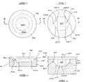
- Figures 1 and 2 are plan and sectional side views, respectively, of an embodiment of the invention,
- Figures 3 and 4 are plan and sectional side views, respectively, of a second embodiment of the invention,
- Figures 5 and 6 are plan and sectional side views, respectively, of a third embodiment of the invention, and
- Figures 7 and 8 are plan and sectional side views, respectively, of a fourth embodiment of the invention.
- The material-filled recess and its location in the cemented carbide substrate has the effect of introducing a compressive pre-stress in the abrasive compact layer thereby strengthening that layer and reducing the incidence of spalling and breakage during use.
- The material-filled recess has a side wall and a base which are both located entirely within the carbide substrate. This means that the entire side wall and the base will be provided and defined by the carbide substrate. The side wall may have one or more discontinuities in it, e.g. can be of square, rectangular or polygonal shape or it can be circular. The recess also has a portion which is located in the interface. The area of that portion is at least 25 percent of the area of the interface. Generally, the area of the portion of the recess in the interface will be less than 95 percent of the area of the interface. Preferably, the area of the portion of the recess in the interface will be 40 to 75 percent of the area of the interface.
- The recess may extend a substantial depth into the substrate. The depth will depend on various factors such as the nature of the material which fills the recess and the shape and configuration of the recess.
- The recess is entirely surrounded by carbide and will typically be centrally located in the substrate. This will generally mean that the portion of the recess which is located in the interface will also be centrally located therein.
- The recess preferably has a right-circular cylindrical shape. With such a shape, it is preferred that the base has one or more concentric steps, each successive step extending deeper into the substrate from the interface as the steps progress towards the centre of the base.
- The base of the recess may have one or more discontinuities which, when provided, are preferably provided by surfaces which define an angle therebetween.
- It is important that the recess be filled with material that is different to the substrate and such as to produce in the compact layer, on manufacture, a compressive pre-stress which strengthens that layer. To achieve this, the material will typically be stiffer than the carbide of the substrate, and may also have greater thermal shrinkage and/or thermal expansion properties than the carbide of the substrate.
- In one preferred form of the invention, the material is abrasive compact which is the same as the abrasive compact layer. This preferred aspect of the invention has particular application to tool components wherein the abrasive compact layer is a diamond abrasive compact layer.
- The material filling the recess may also be a cemented carbide having diamond particles dispersed therein, or a cemented carbide having different characteristics to that of the substrate, e.g. a coarser grain size and/or a high metal binder content.
- The cemented carbide for the substrate may be any known in the art such as cemented titanium carbide, cemented tungsten carbide, cemented tantalum carbide, cemented molybdenum carbide, or mixtures thereof. As is known, such cemented carbides will typically have a metal binder content of 3 to 30 percent by mass. The metal binder will typically be cobalt, iron or nickel or an alloy containing one or more of these metals.
- The abrasive compact has a working surface on a side opposite to the interface between the compact layer and the cemented carbide substrate. This surface is flat and presents a cutting edge or point in its periphery. Typically, this layer will be circular in plan and the circular periphery will provide a cutting edge.
- The tool components of the invention have particular application in rotary drill bits used for drilling earth formations.
- Embodiments of the invention will now be described with reference to the accompanying drawings. Referring first to Figures 1 and 2, a tool component comprises an abrasive
compact layer 10 bonded to a cementedcarbide substrate 12 along aninterface 14. The abrasivecompact layer 10 has an upper flat workingsurface 16 having acircular periphery 18 which provides a cutting edge for the component. - A
recess 20 extends from theinterface 14 into the cementedcarbide substrate 12. The recess is disc-shaped and hasside walls 22 and abase 24. It will be noted that the recess is surrounded by carbide and is located entirely within the carbide substrate. - The
recess 20 is filled with the same abrasive compact as that of thelayer 10. - The compact-filled
recess 20 has a portion, shown by thedotted lines 26 in Figure 2, which is located in theinterface 14. Thisportion 26 has an area at least 25 percent the area of theinterface 14. - A second embodiment of the invention is illustrated by Figures 3 and 4. Referring to these figures, a tool component comprises an abrasive
compact layer 30 bonded to a cementedcarbide substrate 32 along aninterface 34. The abrasivecompact layer 30 has an upper workingsurface 36 which is flat and which has acircular periphery 38. It is thiscircular periphery 38 which provides a cutting edge for the component. - A
recess 40 extends into thesubstrate 32 from theinterface 34. Therecess 40 is disc-shaped havingside walls 42 and a steppedbase 44. The stepped base has twosteps 44a and 44b. The steps extend deeper into thesubstrate 32 as they progress towards the centre of the base. Thus, step 44b is lower thanstep 44a. The lowermost surface of the base is shown by 44c. - The
recess 40 is filled with the same abrasive compact as that oflayer 30. - The recess has a portion, indicated by the dotted
lines 46 in Figure 4, located in theinterface 34. This portion has an area at least 25 percent the area of the interface. - The embodiment of Figures 5 and 6 is similar to that of Figures 3 and 4 and like parts carry like numerals. This embodiment differs from that of Figures 3 and 4 in that only one
step 44a is provided. The lowermost part of thebase 44 is again indicated by 44c. - A fourth embodiment of the invention is illustrated by Figures 7 and 8. Referring to these figures, a tool component comprises an abrasive
compact layer 50 bonded to a cementedcarbide substrate 52 along an interface 54. The abrasivecompact layer 50 has an upper workingsurface 56 which is flat and which has acircular periphery 58. It is thiscircular periphery 58 which provides a cutting edge for the component. - A recess 60 extends into the
substrate 52 from the interface 54. The recess 60 has acentral portion 62 andside portions 64. This results in aperipheral side wall 66 of hexagonal shape which has several discontinuities in it, as can be seen at 66a to 66f in Figure 7. Thebase 68 of the recess is provided by a flat lower section 68a and sloping side sections 68b. - The recess 60 is filled with the same abrasive compact layer as that of the
layer 50. - The recess 60 has a portion, indicated by
dotted lines 70 in Figure 8, located in the interface 54. This portion has an area at least 25 percent the area of the interface. - The tool components illustrated above may be made by methods generally known in the art. For example, a cemented carbide substrate or green form thereof, may have an appropriately shaped recess formed in one surface thereof and the components necessary to produce an abrasive compact placed on the surface of the substrate which has the recess formed therein. This unbonded assembly is then subjected to the elevated temperature and pressure conditions required to produce an abrasive compact of the components. These conditions and the apparatus used for carrying out such a method are well known in the art.
Claims (15)
- A tool component comprising an abrasive compact layer (10) bonded to a cemented carbide substrate (12) along an interface (14);
the abrasive compact layer (10) having a working surface (16), on a side opposite to the interface (14), which is flat and which presents a cutting edge or point on its periphery (18);
a recess (20) extending into the substrate (12) from the interface (14), the recess (20) having a side wall (22) and a base (24) both of which are located entirely within the carbide substrate (12) and a portion (26) in the interface (14) which has an area being at least 25 percent of the area of the interface (14); and
a material completely filling the recess and being bonded to the substrate, the material being different to that of the substrate. - A tool component according to claim 1 wherein the area of the portion (26) of the recess (20) in the interface (14) is less than 95 percent of the area of the interface (14).
- A tool component according to claim 1 wherein the area of the portion (26) of the recess (20) in the interface (14) is 40 to 75 percent of the area of the interface (14).
- A tool component according to any one of the preceding claims wherein the recess (20) is centrally located in the substrate (12).
- A tool component according to any one of the preceding claims wherein the recess (20) is right-circular cylindrical in shape.
- A tool component according to any one of the preceding claims wherein the base (44) of the recess has one or more discontinuities (44a, 44b).
- A tool component according to claim 6 wherein the or each discontinuity (44a, 44b) is provided by surfaces which define an angle therebetween.
- A tool component according to any one of claims 1 to 4 wherein the recess (40) is right-circular cylindrical in shape and the base (44) has one or more concentric steps (44a, 44b), each successive step extending deeper into the substrate (12) from the interface (14) as the steps (44a, 44b) progress towards the centre of the base (44).
- A tool component according to any one of claims 1 to 4 wherein the side wall (66) of the recess has one or more discontinuities (66a to 66f) in it.
- A tool component according to any one of the preceding claims wherein the material filling the recess (20) is stiffer than the carbide of the substrate (12).
- A tool component according to any one of the preceding claims wherein the material filling the recess (20) has greater shrinkage and/or thermal expansion properties than the carbide of the substrate (12).
- A tool component according to any one of the preceding claims wherein the material filling the recess (20) is abrasive compact which is the same as the abrasive compact layer (10).
- A tool component according to claim 12 wherein the abrasive compact is diamond abrasive compact.
- A tool component according to any one of claims 1 to 11 wherein the material filling the recess (20) is cemented carbide having a different characteristic to the carbide of the substrate (12).
- A tool component according to claim 14 wherein the carbide filling the recess (20) differs from the cemented carbide of the substrate (12) in grain size and/or metal binder content.
Applications Claiming Priority (6)
| Application Number | Priority Date | Filing Date | Title |
|---|---|---|---|
| ZA9210000 | 1992-12-23 | ||
| ZA9210000 | 1992-12-23 | ||
| ZA934914 | 1993-07-08 | ||
| ZA934914 | 1993-07-08 | ||
| ZA938170 | 1993-11-02 | ||
| ZA938170 | 1993-11-02 |
Publications (2)
| Publication Number | Publication Date |
|---|---|
| EP0604211A1 true EP0604211A1 (en) | 1994-06-29 |
| EP0604211B1 EP0604211B1 (en) | 1997-04-23 |
Family
ID=27420977
Family Applications (1)
| Application Number | Title | Priority Date | Filing Date |
|---|---|---|---|
| EP93310411A Expired - Lifetime EP0604211B1 (en) | 1992-12-23 | 1993-12-22 | Composite tool for drilling bits |
Country Status (5)
| Country | Link |
|---|---|
| US (1) | US5472376A (en) |
| EP (1) | EP0604211B1 (en) |
| AU (1) | AU670642B2 (en) |
| CA (1) | CA2112143C (en) |
| DE (1) | DE69310123T2 (en) |
Cited By (22)
| Publication number | Priority date | Publication date | Assignee | Title |
|---|---|---|---|---|
| EP0655548A1 (en) * | 1993-11-10 | 1995-05-31 | Camco Drilling Group Limited | Improvements in or relating to cutting elements for rotary drill bits |
| EP0687797A1 (en) * | 1994-06-18 | 1995-12-20 | Camco Drilling Group Limited | Improvements in or relating to elements faced with superhard material |
| GB2290329A (en) * | 1994-06-17 | 1995-12-20 | Baker Hughes Inc | Drill bit cutting element |
| FR2736293A1 (en) * | 1995-07-03 | 1997-01-10 | De Beers Ind Diamond | TOOL COMPONENT |
| WO1997030264A2 (en) * | 1996-02-15 | 1997-08-21 | Baker Hughes Incorporated | Predominantly diamond cutting structures for earth boring |
| EP0692607A3 (en) * | 1994-06-16 | 1997-09-10 | De Beers Ind Diamond | Tool component with abrasive compact |
| EP0716215A3 (en) * | 1994-12-09 | 1998-03-18 | Baker Hughes Incorporated | Superhard cutting structures for earth boring with enhanced stiffness and heat transfer capabilities |
| EP0918134A1 (en) * | 1997-11-20 | 1999-05-26 | General Electric Company | Polycrystalline diamond compact cutter with reduced failure during brazing |
| EP0936012A1 (en) * | 1998-02-13 | 1999-08-18 | Camco International (UK) Limited | Elements faced with superhard material |
| EP0967037A2 (en) | 1998-05-04 | 1999-12-29 | General Electric Company | Polycrystalline diamond compact cutter with interface |
| WO2000001918A1 (en) * | 1998-07-06 | 2000-01-13 | De Beers Industrial Diamonds (Proprietary) Limited | Abrasive body |
| EP0989282A2 (en) * | 1998-09-24 | 2000-03-29 | Camco International (UK) Limited | Improvements in preform cutting elements for rotary drag-type drill bits |
| US6077591A (en) * | 1995-09-23 | 2000-06-20 | Camco International (Uk) Limited | Elements faced with superhard material |
| EP1120541A1 (en) * | 2000-01-27 | 2001-08-01 | General Electric Company | Axisymmetric cutting element |
| SG84595A1 (en) * | 1999-05-18 | 2001-11-20 | Sumitomo Electric Industries | A polycrystal diamond tool |
| WO2012010646A3 (en) * | 2010-07-21 | 2013-01-31 | Element Six Abrasives S.A. | Superhard construction |
| US8936659B2 (en) | 2010-04-14 | 2015-01-20 | Baker Hughes Incorporated | Methods of forming diamond particles having organic compounds attached thereto and compositions thereof |
| US8985248B2 (en) | 2010-08-13 | 2015-03-24 | Baker Hughes Incorporated | Cutting elements including nanoparticles in at least one portion thereof, earth-boring tools including such cutting elements, and related methods |
| US9140072B2 (en) | 2013-02-28 | 2015-09-22 | Baker Hughes Incorporated | Cutting elements including non-planar interfaces, earth-boring tools including such cutting elements, and methods of forming cutting elements |
| US9962669B2 (en) | 2011-09-16 | 2018-05-08 | Baker Hughes Incorporated | Cutting elements and earth-boring tools including a polycrystalline diamond material |
| US10005672B2 (en) | 2010-04-14 | 2018-06-26 | Baker Hughes, A Ge Company, Llc | Method of forming particles comprising carbon and articles therefrom |
| US10066441B2 (en) | 2010-04-14 | 2018-09-04 | Baker Hughes Incorporated | Methods of fabricating polycrystalline diamond, and cutting elements and earth-boring tools comprising polycrystalline diamond |
Families Citing this family (40)
| Publication number | Priority date | Publication date | Assignee | Title |
|---|---|---|---|---|
| US5908071A (en) * | 1995-09-22 | 1999-06-01 | Weatherford/Lamb, Inc. | Wellbore mills and inserts |
| US6170576B1 (en) | 1995-09-22 | 2001-01-09 | Weatherford/Lamb, Inc. | Mills for wellbore operations |
| US5984005A (en) * | 1995-09-22 | 1999-11-16 | Weatherford/Lamb, Inc. | Wellbore milling inserts and mills |
| US5706906A (en) * | 1996-02-15 | 1998-01-13 | Baker Hughes Incorporated | Superabrasive cutting element with enhanced durability and increased wear life, and apparatus so equipped |
| US5758733A (en) * | 1996-04-17 | 1998-06-02 | Baker Hughes Incorporated | Earth-boring bit with super-hard cutting elements |
| US6571891B1 (en) | 1996-04-17 | 2003-06-03 | Baker Hughes Incorporated | Web cutter |
| US6068071A (en) * | 1996-05-23 | 2000-05-30 | U.S. Synthetic Corporation | Cutter with polycrystalline diamond layer and conic section profile |
| US6148937A (en) * | 1996-06-13 | 2000-11-21 | Smith International, Inc. | PDC cutter element having improved substrate configuration |
| US5906246A (en) * | 1996-06-13 | 1999-05-25 | Smith International, Inc. | PDC cutter element having improved substrate configuration |
| US5711702A (en) * | 1996-08-27 | 1998-01-27 | Tempo Technology Corporation | Curve cutter with non-planar interface |
| GB9703571D0 (en) * | 1997-02-20 | 1997-04-09 | De Beers Ind Diamond | Diamond-containing body |
| US5871060A (en) * | 1997-02-20 | 1999-02-16 | Jensen; Kenneth M. | Attachment geometry for non-planar drill inserts |
| US5979579A (en) * | 1997-07-11 | 1999-11-09 | U.S. Synthetic Corporation | Polycrystalline diamond cutter with enhanced durability |
| US6149695A (en) * | 1998-03-09 | 2000-11-21 | Adia; Moosa Mahomed | Abrasive body |
| US5971087A (en) | 1998-05-20 | 1999-10-26 | Baker Hughes Incorporated | Reduced residual tensile stress superabrasive cutters for earth boring and drill bits so equipped |
| GB9811705D0 (en) * | 1998-06-02 | 1998-07-29 | Camco Int Uk Ltd | Preform cutting elements for rotary drill bits |
| US6527069B1 (en) | 1998-06-25 | 2003-03-04 | Baker Hughes Incorporated | Superabrasive cutter having optimized table thickness and arcuate table-to-substrate interfaces |
| US6412580B1 (en) | 1998-06-25 | 2002-07-02 | Baker Hughes Incorporated | Superabrasive cutter with arcuate table-to-substrate interfaces |
| US6148938A (en) * | 1998-10-20 | 2000-11-21 | Dresser Industries, Inc. | Wear resistant cutter insert structure and method |
| US6227319B1 (en) * | 1999-07-01 | 2001-05-08 | Baker Hughes Incorporated | Superabrasive cutting elements and drill bit so equipped |
| US6213931B1 (en) * | 1999-12-09 | 2001-04-10 | Dennis Tool Company | Stump grinding tooth |
| DE10209924A1 (en) * | 2002-03-07 | 2003-09-25 | Beck August Gmbh Co | Guide bar for strip-guided cutting tools |
| US7470341B2 (en) * | 2002-09-18 | 2008-12-30 | Smith International, Inc. | Method of manufacturing a cutting element from a partially densified substrate |
| US20050146199A1 (en) * | 2004-01-05 | 2005-07-07 | Wen-Chin Lee | Rotatable cutting tool for breaking hard material |
| US7243745B2 (en) * | 2004-07-28 | 2007-07-17 | Baker Hughes Incorporated | Cutting elements and rotary drill bits including same |
| US7287610B2 (en) * | 2004-09-29 | 2007-10-30 | Smith International, Inc. | Cutting elements and bits incorporating the same |
| US7493972B1 (en) | 2006-08-09 | 2009-02-24 | Us Synthetic Corporation | Superabrasive compact with selected interface and rotary drill bit including same |
| WO2011084864A2 (en) | 2009-12-31 | 2011-07-14 | Diamond Innovations, Inc. | Machining tool blank |
| GB2491306B (en) * | 2010-06-16 | 2013-06-12 | Element Six Abrasives Sa | Superhard cutter |
| US8899358B2 (en) * | 2010-10-28 | 2014-12-02 | Smith International, Inc. | Interface design of TSP shear cutters |
| GB201021741D0 (en) * | 2010-12-22 | 2011-02-02 | Element Six Production Pty Ltd | Cutting element |
| US8727045B1 (en) | 2011-02-23 | 2014-05-20 | Us Synthetic Corporation | Polycrystalline diamond compacts, methods of making same, and applications therefor |
| US9534450B2 (en) | 2013-07-22 | 2017-01-03 | Baker Hughes Incorporated | Thermally stable polycrystalline compacts for reduced spalling, earth-boring tools including such compacts, and related methods |
| CA2919163C (en) * | 2013-08-30 | 2018-01-16 | Halliburton Energy Services, Inc. | Improved cutters for drill bits |
| CN103758459B (en) * | 2014-01-21 | 2016-05-18 | 西南石油大学 | Prevent tooth profile of tooth and the inserting method of hole wall plastic deformation |
| US9845642B2 (en) | 2014-03-17 | 2017-12-19 | Baker Hughes Incorporated | Cutting elements having non-planar cutting faces with selectively leached regions, earth-boring tools including such cutting elements, and related methods |
| US9605488B2 (en) | 2014-04-08 | 2017-03-28 | Baker Hughes Incorporated | Cutting elements including undulating boundaries between catalyst-containing and catalyst-free regions of polycrystalline superabrasive materials and related earth-boring tools and methods |
| US9714545B2 (en) | 2014-04-08 | 2017-07-25 | Baker Hughes Incorporated | Cutting elements having a non-uniform annulus leach depth, earth-boring tools including such cutting elements, and related methods |
| US9863189B2 (en) | 2014-07-11 | 2018-01-09 | Baker Hughes Incorporated | Cutting elements comprising partially leached polycrystalline material, tools comprising such cutting elements, and methods of forming wellbores using such cutting elements |
| CN107532455A (en) * | 2015-06-24 | 2018-01-02 | 哈利伯顿能源服务公司 | Away drill cuttings and knife combination part |
Citations (4)
| Publication number | Priority date | Publication date | Assignee | Title |
|---|---|---|---|---|
| EP0157278A2 (en) * | 1984-03-26 | 1985-10-09 | Eastman Christensen Company | Multi-component cutting element using polycrystalline diamond disks |
| EP0322214A1 (en) * | 1987-12-22 | 1989-06-28 | De Beers Industrial Diamond Division (Proprietary) Limited | Abrasive product |
| EP0462955A1 (en) * | 1990-06-15 | 1991-12-27 | Sandvik Aktiebolag | Improved tools for cutting rock drilling |
| WO1992015427A1 (en) * | 1991-03-05 | 1992-09-17 | Diamant-Boart Stratabit (Usa) Inc. | Cutting composite formed of cemented carbide substrate and diamond layer |
Family Cites Families (7)
| Publication number | Priority date | Publication date | Assignee | Title |
|---|---|---|---|---|
| US4109737A (en) * | 1976-06-24 | 1978-08-29 | General Electric Company | Rotary drill bit |
| AU577958B2 (en) * | 1985-08-22 | 1988-10-06 | De Beers Industrial Diamond Division (Proprietary) Limited | Abrasive compact |
| US4784023A (en) * | 1985-12-05 | 1988-11-15 | Diamant Boart-Stratabit (Usa) Inc. | Cutting element having composite formed of cemented carbide substrate and diamond layer and method of making same |
| US4714385A (en) * | 1986-02-27 | 1987-12-22 | General Electric Company | Polycrystalline diamond and CBN cutting tools |
| DE3784662T2 (en) * | 1986-12-23 | 1993-06-24 | De Beers Ind Diamond | TOOL INSERT. |
| AU602256B2 (en) * | 1987-10-12 | 1990-10-04 | De Beers Industrial Diamond Division (Proprietary) Limited | Abrasive products |
| ATE114356T1 (en) * | 1988-08-15 | 1994-12-15 | De Beers Ind Diamond | TOOL USE. |
-
1993
- 1993-12-21 AU AU52607/93A patent/AU670642B2/en not_active Ceased
- 1993-12-22 EP EP93310411A patent/EP0604211B1/en not_active Expired - Lifetime
- 1993-12-22 CA CA002112143A patent/CA2112143C/en not_active Expired - Fee Related
- 1993-12-22 US US08/172,412 patent/US5472376A/en not_active Expired - Lifetime
- 1993-12-22 DE DE69310123T patent/DE69310123T2/en not_active Expired - Fee Related
Patent Citations (4)
| Publication number | Priority date | Publication date | Assignee | Title |
|---|---|---|---|---|
| EP0157278A2 (en) * | 1984-03-26 | 1985-10-09 | Eastman Christensen Company | Multi-component cutting element using polycrystalline diamond disks |
| EP0322214A1 (en) * | 1987-12-22 | 1989-06-28 | De Beers Industrial Diamond Division (Proprietary) Limited | Abrasive product |
| EP0462955A1 (en) * | 1990-06-15 | 1991-12-27 | Sandvik Aktiebolag | Improved tools for cutting rock drilling |
| WO1992015427A1 (en) * | 1991-03-05 | 1992-09-17 | Diamant-Boart Stratabit (Usa) Inc. | Cutting composite formed of cemented carbide substrate and diamond layer |
Cited By (39)
| Publication number | Priority date | Publication date | Assignee | Title |
|---|---|---|---|---|
| EP0655548A1 (en) * | 1993-11-10 | 1995-05-31 | Camco Drilling Group Limited | Improvements in or relating to cutting elements for rotary drill bits |
| US5598750A (en) * | 1993-11-10 | 1997-02-04 | Camco Drilling Group Limited | Elements faced with superhard material |
| EP0692607A3 (en) * | 1994-06-16 | 1997-09-10 | De Beers Ind Diamond | Tool component with abrasive compact |
| GB2290329A (en) * | 1994-06-17 | 1995-12-20 | Baker Hughes Inc | Drill bit cutting element |
| US5492188A (en) * | 1994-06-17 | 1996-02-20 | Baker Hughes Incorporated | Stress-reduced superhard cutting element |
| GB2290329B (en) * | 1994-06-17 | 1998-12-16 | Baker Hughes Inc | Stress-reduced superhard cutting element |
| EP0687797A1 (en) * | 1994-06-18 | 1995-12-20 | Camco Drilling Group Limited | Improvements in or relating to elements faced with superhard material |
| EP0716215A3 (en) * | 1994-12-09 | 1998-03-18 | Baker Hughes Incorporated | Superhard cutting structures for earth boring with enhanced stiffness and heat transfer capabilities |
| DE19625509B4 (en) * | 1995-07-03 | 2007-01-18 | De Beers Industrial Diamond Division (Proprietary) Ltd., Johannesburg | Tool component for cutting bit made of cemented carbide substrate and use for producing a cutting bit |
| GB2302893B (en) * | 1995-07-03 | 1998-09-16 | De Beers Ind Diamond | Tool component |
| GB2302893A (en) * | 1995-07-03 | 1997-02-05 | De Beers Ind Diamond | Tool component |
| US6283844B1 (en) | 1995-07-03 | 2001-09-04 | Klaus Tank | Tool component |
| FR2736293A1 (en) * | 1995-07-03 | 1997-01-10 | De Beers Ind Diamond | TOOL COMPONENT |
| US6077591A (en) * | 1995-09-23 | 2000-06-20 | Camco International (Uk) Limited | Elements faced with superhard material |
| WO1997030264A2 (en) * | 1996-02-15 | 1997-08-21 | Baker Hughes Incorporated | Predominantly diamond cutting structures for earth boring |
| WO1997030264A3 (en) * | 1996-02-15 | 1997-10-30 | Baker Hughes Inc | Predominantly diamond cutting structures for earth boring |
| US6042463A (en) * | 1997-11-20 | 2000-03-28 | General Electric Company | Polycrystalline diamond compact cutter with reduced failure during brazing |
| EP0918134A1 (en) * | 1997-11-20 | 1999-05-26 | General Electric Company | Polycrystalline diamond compact cutter with reduced failure during brazing |
| EP0936012A1 (en) * | 1998-02-13 | 1999-08-18 | Camco International (UK) Limited | Elements faced with superhard material |
| EP0967037A2 (en) | 1998-05-04 | 1999-12-29 | General Electric Company | Polycrystalline diamond compact cutter with interface |
| EP0967037A3 (en) * | 1998-05-04 | 2007-07-25 | Diamond Innovations, Inc. | Polycrystalline diamond compact cutter with interface |
| WO2000001918A1 (en) * | 1998-07-06 | 2000-01-13 | De Beers Industrial Diamonds (Proprietary) Limited | Abrasive body |
| US6527633B1 (en) | 1998-07-06 | 2003-03-04 | Klaus Tank | Abrasive body |
| EP0989282A2 (en) * | 1998-09-24 | 2000-03-29 | Camco International (UK) Limited | Improvements in preform cutting elements for rotary drag-type drill bits |
| EP0989282A3 (en) * | 1998-09-24 | 2002-01-30 | Camco International (UK) Limited | Improvements in preform cutting elements for rotary drag-type drill bits |
| SG84595A1 (en) * | 1999-05-18 | 2001-11-20 | Sumitomo Electric Industries | A polycrystal diamond tool |
| EP1120541A1 (en) * | 2000-01-27 | 2001-08-01 | General Electric Company | Axisymmetric cutting element |
| US10066441B2 (en) | 2010-04-14 | 2018-09-04 | Baker Hughes Incorporated | Methods of fabricating polycrystalline diamond, and cutting elements and earth-boring tools comprising polycrystalline diamond |
| US10005672B2 (en) | 2010-04-14 | 2018-06-26 | Baker Hughes, A Ge Company, Llc | Method of forming particles comprising carbon and articles therefrom |
| US8936659B2 (en) | 2010-04-14 | 2015-01-20 | Baker Hughes Incorporated | Methods of forming diamond particles having organic compounds attached thereto and compositions thereof |
| US9701877B2 (en) | 2010-04-14 | 2017-07-11 | Baker Hughes Incorporated | Compositions of diamond particles having organic compounds attached thereto |
| CN103154419B (en) * | 2010-07-21 | 2016-08-03 | 第六元素研磨剂股份有限公司 | Superhard construction |
| US9382763B2 (en) | 2010-07-21 | 2016-07-05 | Element Six Abrasives S.A. | Superhard construction |
| CN103154419A (en) * | 2010-07-21 | 2013-06-12 | 第六元素研磨剂股份有限公司 | Superhard construction |
| WO2012010646A3 (en) * | 2010-07-21 | 2013-01-31 | Element Six Abrasives S.A. | Superhard construction |
| US8985248B2 (en) | 2010-08-13 | 2015-03-24 | Baker Hughes Incorporated | Cutting elements including nanoparticles in at least one portion thereof, earth-boring tools including such cutting elements, and related methods |
| US9797201B2 (en) | 2010-08-13 | 2017-10-24 | Baker Hughes Incorporated | Cutting elements including nanoparticles in at least one region thereof, earth-boring tools including such cutting elements, and related methods |
| US9962669B2 (en) | 2011-09-16 | 2018-05-08 | Baker Hughes Incorporated | Cutting elements and earth-boring tools including a polycrystalline diamond material |
| US9140072B2 (en) | 2013-02-28 | 2015-09-22 | Baker Hughes Incorporated | Cutting elements including non-planar interfaces, earth-boring tools including such cutting elements, and methods of forming cutting elements |
Also Published As
| Publication number | Publication date |
|---|---|
| CA2112143C (en) | 2005-07-26 |
| DE69310123D1 (en) | 1997-05-28 |
| US5472376A (en) | 1995-12-05 |
| CA2112143A1 (en) | 1994-06-24 |
| DE69310123T2 (en) | 1997-07-31 |
| AU5260793A (en) | 1994-07-07 |
| AU670642B2 (en) | 1996-07-25 |
| EP0604211B1 (en) | 1997-04-23 |
Similar Documents
| Publication | Publication Date | Title |
|---|---|---|
| US5472376A (en) | Tool component | |
| US20200149353A1 (en) | Polycrystalline Diamond Cutting Element | |
| US6408959B2 (en) | Polycrystalline diamond compact cutter having a stress mitigating hoop at the periphery | |
| US8016054B2 (en) | Polycrystalline diamond abrasive elements | |
| US6258139B1 (en) | Polycrystalline diamond cutter with an integral alternative material core | |
| US7070635B2 (en) | Self sharpening polycrystalline diamond compact with high impact resistance | |
| US5645617A (en) | Composite polycrystalline diamond compact with improved impact and thermal stability | |
| EP0582484B1 (en) | Tool insert | |
| US8020644B2 (en) | Thermally stable polycrystalline diamond materials, cutting elements incorporating the same and bits incorporating such cutting elements | |
| US6272753B2 (en) | Multi-layer, multi-grade multiple cutting surface PDC cutter | |
| US5027912A (en) | Drill bit having improved cutter configuration | |
| US5871060A (en) | Attachment geometry for non-planar drill inserts | |
| US5979579A (en) | Polycrystalline diamond cutter with enhanced durability | |
| CA2151899C (en) | Tool component | |
| JPH06212874A (en) | Cemented carbide bit button | |
| JPH106228A (en) | Improved abrasive cutting element and drill bit | |
| US6149695A (en) | Abrasive body | |
| US5685769A (en) | Tool component | |
| GB2041427A (en) | Insert for tool wear surfaces and method of manufacture | |
| EP0350045A2 (en) | Drill bit with composite cutting members | |
| ZA200509523B (en) | Polycrystalline diamond abrasive elements |
Legal Events
| Date | Code | Title | Description |
|---|---|---|---|
| PUAI | Public reference made under article 153(3) epc to a published international application that has entered the european phase |
Free format text: ORIGINAL CODE: 0009012 |
|
| AK | Designated contracting states |
Kind code of ref document: A1 Designated state(s): BE DE FR GB IE SE |
|
| 17P | Request for examination filed |
Effective date: 19940523 |
|
| 17Q | First examination report despatched |
Effective date: 19951121 |
|
| GRAG | Despatch of communication of intention to grant |
Free format text: ORIGINAL CODE: EPIDOS AGRA |
|
| GRAH | Despatch of communication of intention to grant a patent |
Free format text: ORIGINAL CODE: EPIDOS IGRA |
|
| RAP1 | Party data changed (applicant data changed or rights of an application transferred) |
Owner name: DE BEERS INDUSTRIAL DIAMOND DIVISION (PROPRIETARY) |
|
| GRAH | Despatch of communication of intention to grant a patent |
Free format text: ORIGINAL CODE: EPIDOS IGRA |
|
| GRAA | (expected) grant |
Free format text: ORIGINAL CODE: 0009210 |
|
| AK | Designated contracting states |
Kind code of ref document: B1 Designated state(s): BE DE FR GB IE SE |
|
| REF | Corresponds to: |
Ref document number: 69310123 Country of ref document: DE Date of ref document: 19970528 |
|
| REG | Reference to a national code |
Ref country code: IE Ref legal event code: FG4D Free format text: 73537 |
|
| ET | Fr: translation filed | ||
| PLBE | No opposition filed within time limit |
Free format text: ORIGINAL CODE: 0009261 |
|
| STAA | Information on the status of an ep patent application or granted ep patent |
Free format text: STATUS: NO OPPOSITION FILED WITHIN TIME LIMIT |
|
| 26N | No opposition filed | ||
| REG | Reference to a national code |
Ref country code: GB Ref legal event code: IF02 |
|
| PGFP | Annual fee paid to national office [announced via postgrant information from national office to epo] |
Ref country code: SE Payment date: 20071205 Year of fee payment: 15 |
|
| PGFP | Annual fee paid to national office [announced via postgrant information from national office to epo] |
Ref country code: GB Payment date: 20071219 Year of fee payment: 15 Ref country code: FR Payment date: 20071210 Year of fee payment: 15 |
|
| PGFP | Annual fee paid to national office [announced via postgrant information from national office to epo] |
Ref country code: DE Payment date: 20071220 Year of fee payment: 15 |
|
| PGFP | Annual fee paid to national office [announced via postgrant information from national office to epo] |
Ref country code: BE Payment date: 20080314 Year of fee payment: 15 |
|
| BERE | Be: lapsed |
Owner name: *DE BEERS INDUSTRIAL DIAMOND DIVISION (PROPRIETARY Effective date: 20081231 |
|
| EUG | Se: european patent has lapsed | ||
| GBPC | Gb: european patent ceased through non-payment of renewal fee |
Effective date: 20081222 |
|
| PGFP | Annual fee paid to national office [announced via postgrant information from national office to epo] |
Ref country code: IE Payment date: 20071212 Year of fee payment: 15 |
|
| REG | Reference to a national code |
Ref country code: IE Ref legal event code: MM4A |
|
| PG25 | Lapsed in a contracting state [announced via postgrant information from national office to epo] |
Ref country code: BE Free format text: LAPSE BECAUSE OF NON-PAYMENT OF DUE FEES Effective date: 20081231 |
|
| REG | Reference to a national code |
Ref country code: FR Ref legal event code: ST Effective date: 20090831 |
|
| PG25 | Lapsed in a contracting state [announced via postgrant information from national office to epo] |
Ref country code: IE Free format text: LAPSE BECAUSE OF NON-PAYMENT OF DUE FEES Effective date: 20081222 Ref country code: DE Free format text: LAPSE BECAUSE OF NON-PAYMENT OF DUE FEES Effective date: 20090701 |
|
| PG25 | Lapsed in a contracting state [announced via postgrant information from national office to epo] |
Ref country code: GB Free format text: LAPSE BECAUSE OF NON-PAYMENT OF DUE FEES Effective date: 20081222 |
|
| PG25 | Lapsed in a contracting state [announced via postgrant information from national office to epo] |
Ref country code: FR Free format text: LAPSE BECAUSE OF NON-PAYMENT OF DUE FEES Effective date: 20081231 |
|
| PG25 | Lapsed in a contracting state [announced via postgrant information from national office to epo] |
Ref country code: SE Free format text: LAPSE BECAUSE OF NON-PAYMENT OF DUE FEES Effective date: 20081223 |