EP0605841A1 - Diffractive multi-focal lens - Google Patents
Diffractive multi-focal lens Download PDFInfo
- Publication number
- EP0605841A1 EP0605841A1 EP93120648A EP93120648A EP0605841A1 EP 0605841 A1 EP0605841 A1 EP 0605841A1 EP 93120648 A EP93120648 A EP 93120648A EP 93120648 A EP93120648 A EP 93120648A EP 0605841 A1 EP0605841 A1 EP 0605841A1
- Authority
- EP
- European Patent Office
- Prior art keywords
- diffractive
- lens
- function
- focal
- orders
- Prior art date
- Legal status (The legal status is an assumption and is not a legal conclusion. Google has not performed a legal analysis and makes no representation as to the accuracy of the status listed.)
- Withdrawn
Links
Images


Classifications
-
- G—PHYSICS
- G02—OPTICS
- G02B—OPTICAL ELEMENTS, SYSTEMS OR APPARATUS
- G02B5/00—Optical elements other than lenses
- G02B5/18—Diffraction gratings
- G02B5/1876—Diffractive Fresnel lenses; Zone plates; Kinoforms
- G02B5/189—Structurally combined with optical elements not having diffractive power
- G02B5/1895—Structurally combined with optical elements not having diffractive power such optical elements having dioptric power
-
- A—HUMAN NECESSITIES
- A61—MEDICAL OR VETERINARY SCIENCE; HYGIENE
- A61F—FILTERS IMPLANTABLE INTO BLOOD VESSELS; PROSTHESES; DEVICES PROVIDING PATENCY TO, OR PREVENTING COLLAPSING OF, TUBULAR STRUCTURES OF THE BODY, e.g. STENTS; ORTHOPAEDIC, NURSING OR CONTRACEPTIVE DEVICES; FOMENTATION; TREATMENT OR PROTECTION OF EYES OR EARS; BANDAGES, DRESSINGS OR ABSORBENT PADS; FIRST-AID KITS
- A61F2/00—Filters implantable into blood vessels; Prostheses, i.e. artificial substitutes or replacements for parts of the body; Appliances for connecting them with the body; Devices providing patency to, or preventing collapsing of, tubular structures of the body, e.g. stents
- A61F2/02—Prostheses implantable into the body
- A61F2/14—Eye parts, e.g. lenses, corneal implants; Implanting instruments specially adapted therefor; Artificial eyes
- A61F2/16—Intraocular lenses
- A61F2/1613—Intraocular lenses having special lens configurations, e.g. multipart lenses; having particular optical properties, e.g. pseudo-accommodative lenses, lenses having aberration corrections, diffractive lenses, lenses for variably absorbing electromagnetic radiation, lenses having variable focus
- A61F2/1616—Pseudo-accommodative, e.g. multifocal or enabling monovision
- A61F2/1618—Multifocal lenses
-
- A—HUMAN NECESSITIES
- A61—MEDICAL OR VETERINARY SCIENCE; HYGIENE
- A61F—FILTERS IMPLANTABLE INTO BLOOD VESSELS; PROSTHESES; DEVICES PROVIDING PATENCY TO, OR PREVENTING COLLAPSING OF, TUBULAR STRUCTURES OF THE BODY, e.g. STENTS; ORTHOPAEDIC, NURSING OR CONTRACEPTIVE DEVICES; FOMENTATION; TREATMENT OR PROTECTION OF EYES OR EARS; BANDAGES, DRESSINGS OR ABSORBENT PADS; FIRST-AID KITS
- A61F2/00—Filters implantable into blood vessels; Prostheses, i.e. artificial substitutes or replacements for parts of the body; Appliances for connecting them with the body; Devices providing patency to, or preventing collapsing of, tubular structures of the body, e.g. stents
- A61F2/02—Prostheses implantable into the body
- A61F2/14—Eye parts, e.g. lenses, corneal implants; Implanting instruments specially adapted therefor; Artificial eyes
- A61F2/16—Intraocular lenses
- A61F2/1613—Intraocular lenses having special lens configurations, e.g. multipart lenses; having particular optical properties, e.g. pseudo-accommodative lenses, lenses having aberration corrections, diffractive lenses, lenses for variably absorbing electromagnetic radiation, lenses having variable focus
- A61F2/1654—Diffractive lenses
-
- G—PHYSICS
- G02—OPTICS
- G02B—OPTICAL ELEMENTS, SYSTEMS OR APPARATUS
- G02B5/00—Optical elements other than lenses
- G02B5/18—Diffraction gratings
- G02B5/1876—Diffractive Fresnel lenses; Zone plates; Kinoforms
-
- G—PHYSICS
- G02—OPTICS
- G02C—SPECTACLES; SUNGLASSES OR GOGGLES INSOFAR AS THEY HAVE THE SAME FEATURES AS SPECTACLES; CONTACT LENSES
- G02C7/00—Optical parts
- G02C7/02—Lenses; Lens systems ; Methods of designing lenses
- G02C7/04—Contact lenses for the eyes
- G02C7/041—Contact lenses for the eyes bifocal; multifocal
- G02C7/042—Simultaneous type
-
- G—PHYSICS
- G02—OPTICS
- G02C—SPECTACLES; SUNGLASSES OR GOGGLES INSOFAR AS THEY HAVE THE SAME FEATURES AS SPECTACLES; CONTACT LENSES
- G02C7/00—Optical parts
- G02C7/02—Lenses; Lens systems ; Methods of designing lenses
- G02C7/04—Contact lenses for the eyes
- G02C7/041—Contact lenses for the eyes bifocal; multifocal
- G02C7/044—Annular configuration, e.g. pupil tuned
-
- G—PHYSICS
- G02—OPTICS
- G02C—SPECTACLES; SUNGLASSES OR GOGGLES INSOFAR AS THEY HAVE THE SAME FEATURES AS SPECTACLES; CONTACT LENSES
- G02C2202/00—Generic optical aspects applicable to one or more of the subgroups of G02C7/00
- G02C2202/20—Diffractive and Fresnel lenses or lens portions
Definitions
- the present invention relates to multiple focus lenses in general and, more particularly, to multi-focal, diffractive, ophthalmic lenses.
- ophthalmic lenses Since the fraction of incident light which is utilized by a multiple focal lens is divided between the different focal lengths, such lenses should be constructed to yield high light transmission efficiency. The need for such improved efficiency is particularly important for intraocular multi-focal lenses, since human vision is poor at low light levels.
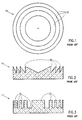
- Fig. 1 which is an anterior view illustration of a multi-focal lens 10, shows a spatially divided lens.
- the lens is sectioned into discrete, adjacent, refractive sections 12 which are, normally, concentric.
- the non-adjacent sections are grouped into a number of groups (typically two), wherein each group corresponds to a single-focus refractive lens, and wherein each section is an optical equivalent of a portion of the corresponding lens.
- each group is a spatially discontinuous, single-focus, refractive lens.
- the fraction of total incident energy focused in accordance with each focal length is, optimally, equal to the fractional area of incidence covered by the respective refractive group.
- lens 10 comprise a large number of sections 12. If the lens is divided into a small number of concentric sections, the relative intensities of the different groups might vary in accordance with the expansion and contraction of the eye pupil.
- U.S. Patent Nos. 4,162,122 and 4,210,391 are concerned with refractive contact lenses which are divided into many concentric annular sections, wherein any two adjacent sections belong to two different focal groups.
- An attempt to spatially divide a contact lens into non-concentric sections is described in U.S. Patent No. 4,704,016.
- a diffraction lens 14 is generally constructed in accordance with a diffractive pattern, i.e. a locally periodic structure which affects the phase and/or amplitude of incident light. This results in a corresponding, transverse, locally periodic, relative-phase structure of the exiting wave front, thereby producing a multi-order diffraction image.
- a diffractive pattern i.e. a locally periodic structure which affects the phase and/or amplitude of incident light.
- the different foci of diffractive lenses do not correspond to different zones of diffraction lens 14. Rather, every point of lens 14 diffracts the incident light into the different diffraction orders which correspond to the different foci.
- Prior art Fresnel phase plates have a typical general structure, which can be seen in Fig. 2, wherein the diffractive pattern comprises a series of one-way optical steps 16.
- Optical steps 16 are defined by sharp drops “d” in lens thickness, which cause a proportional phase difference between adjacent light rays passing through opposite sides of step 16.
- the phase delay caused by drop "d" in height of steps 16 is equal to one half of a design wavelength " ⁇ " which is typical of the wavelengths viewed with the lens. It has been generally believed that best results are achieved when there are a large number of steps and when the drops are very sharp, because some of the incident energy would not, otherwise, be focused to either of the foci.
- U.S. Patent Nos. 4,830,481 and 5,076,684 both describe such lenses.
- U.S. Patent 4,830,481 appears to suggest that the sharp drop "d" can be smoothed to a limited extent, by curving the sharp corners in accordance with a limited radius of curvature (specifically, not more than one or two times the step height), sacrificing just a small fraction of the incident energy. Nevertheless, this reference teaches that some sacrifice in efficiency is a result of such a "smoother" lens.
- a bifocal diffraction Raleigh Wood lens is used in the bifocal microscope described in "Bifocus Microscope" by V.P. Koronkevitch, V.N. Nagorni, I.G. Palchikova and A.G.Poleshchuk, Optik 78, No. 2, 1988, pp. 64-66.
- a Raleigh Wood lens 11 consists of a series of rectangular protrusions 13 separated by a series of rectangular recesses 15, wherein the width of each protrusions is substantially equal to the width of an adjacent recess, i.e. a duty-cycle of 0.5, and wherein the phase difference between the protrusions and the recesses, i.e.
- the step height is approximately equal to ⁇ /2(n2-n1), where ⁇ is the typical wavelength used and n1, n2 are the refractive indices of the lens and the material outside the lens.
- the lens is described as having a light transmission efficiency of 81% divided equally between intense "-1" and "+1" diffraction orders, whereas other orders are negligible.
- This lens has a topographical structure which is periodic in r2.
- a lens can be spatially divided into narrow refractive concentric sections which are also diffractive phase-shift plates, spaced by precalculated distances, such that some diffraction order foci coincide with the refractive foci. Examples of such combinations is described in U.S. Patent Nos. 4,338,005, 4,340,283, and 4,881,805, all issued to Cohen.
- the surfaces of the more efficient of the currently available bi-focal ophthalmic lenses include a series of sharp edged steps, which define a plurality of sharp corners.
- the sharp edges and corners present inevitable difficulties for the user of the lens.
- dirt which is easily collected at the sharp corners is extremely difficult to remove by conventional cleaning instruments and materials.
- the edges of the optical steps can cause undesirable light interference, known as glare, which appear to the eye of the user as disturbing blurry intense light.
- the sharp edged surface can cause uncomfortable irritation to the eyes of the user when the lens is used as a contact lens.
- bi-focal ophthalmic lenses featuring a substantially even distribution of light between their two foci are available. This limitation is especially critical for intraocular lenses where the eye itself has no focusing power. With two focal lengths, the user is often deprived of clear vision in the mid range. There is therefore a need for an efficient intraocular lens having more than two focal lengths. Also, uneven intensity distribution between the foci may be desired such that vision of a preselected distance ranges will be particularly enhanced. For example, reading may require higher transmission efficiency than the efficiency required for viewing landscapes due to the generally different available light intensities.
- a lens constructed and operative in accordance with a preferred embodiment of the present invention effectively focuses incident light in accordance with two or more different focal lengths simultaneously, and maintains an over all light transmission efficiency for more than two foci which is generally comparable with and often substantially better than bi-focal diffraction lenses.
- the high total light transmission efficiency is substantially maintained, in a preferred embodiment of the invention, regardless of whether the incident light is distributed evenly or unevenly among the different foci.
- the present invention also provides an extremely efficient ophthalmic multi-focal diffractive lens having a preselected number of dominant foci and having a preselected distribution of incident light among the different foci.
- the preselected distribution may be even or uneven.
- the other problems of many existing ophthalmic lenses namely those associated with a sharp stepped surface, are also solved by the present invention.
- the surfaces of a lens constructed and operative in accordance with a preferred embodiment of the invention are extremely smooth compared to those of most known diffraction and refraction multi-focal ophthalmic lenses.
- a lens including a diffractive surface.
- the diffractive surface is constructed so that its radial cross-section is shaped in accordance with a diffractive pattern which diffracts most of the incident light energy into three dominant diffraction orders, namely, "-1", "0” and "+1".
- the "+1", "0” and “-1” diffraction orders conventionally represent convergingly diffracted light, divergingly diffracted light and undiffracted light, respectively.
- the incident energy is distributed substantially evenly among the three orders so that each of the three orders carries approximately one third of the transmitted energy.
- the amount of light in the orders is not equal so as to account for the normal lighting conditions of objects at different distance ranges.
- the dominant diffraction orders are preselected and the distribution of light among the dominant orders is preset.
- a lens constructed in accordance with a preferred embodiment of the present invention is further provided with refractive power.
- the surfaces of the lens are appropriately constructed so that undiffracted incident light coming to the lens from a preset distance, which is preferably within an intermediate distance range (i.e. more than reading distance and less than infinity), is refractively focused (with the possible aid of the natural lens and/or cornea of the human eye) onto a given image plane (typically, a human eye retina).
- light from the preset distance defined by the refractive surface is carried onto the image plane by the "0" order, which represents light which is unaffected by the diffractive surface.
- the "-1" order representing light which is diverged by the diffractive surface, focuses light from a longer range (typically infinity) onto the same image plane.
- the "+1" order representing light which is converged by the diffractive surface, focuses light from a shorter range (typically reading distance) onto the same image plane.
- the topographical height at any given point on the diffractive surface is generally a smooth, essentially periodic, function, h, of a function, u(r), of the radial coordinate, r. Furthermore, each period of this periodic function of u(r) is essentially symmetric with respect to u(r). Thus, the periodic function defines gradual, generally symmetric, rising and falling slopes between generally smooth peaks.
- This periodic topographical height function "h” defines an optical height function "h o " which is equal to "h” multiplied by (n2-n1), where n2 and n1 are the refractive indices of the lens material and the surrounding medium (typically air, eye tears of the intraocular fluid), respectively.
- the optical height function is different from ⁇ /2, modulo ⁇ .
- the optical height function is a periodic function, h o , of a function, u(r), of the radial coordinate but the function, h o , is not symmetric. That is to say, during one portion of the period the function of the radial coordinate is different from that in a second portion of the period. More preferably, the spatial frequency of one portion is greater than that of the second portion.
- the surface topographical function, h defines essentially rectangular protrusions which are separated by essentially rectangular recesses.
- the step height of the protrusions determines the absolute intensity of each order as well as the relative intensities among the three diffraction orders.
- the diffractive surface follows a trapezoidal wave topographical pattern.
- the computed imaging efficiency obtained by this embodiment is 92.1%.
- the topographical optical height, h o of any given point on the diffractive surface of the lens, follows the formula: A ⁇ cos(k ⁇ r2+ ⁇ )+C , wherein "r" is the radial coordinate and A, k, and C are preselected parameters which are selected so as to yield the highest possible imaging efficiency.
- ⁇ is a constant.
- This embodiment is preferred over the trapezoidal embodiment, because it combines the smoothness of a sinusoidal pattern with efficiency comparable to that of the trapezoidal pattern. This very smooth embodiment yields an imaging efficiency of approximately 90%.
- the slopes of the trapezoids are made unequal for the "rising” and “falling” portions and, for the sinusoidal function, the sinusoidal frequency is made different for two portions of the period.
- the topographical optical height of the surface follows a generally periodic function of the radial coordinate, wherein each period of the periodic function follows the polynomial function: wherein u (0 ⁇ u ⁇ 2 ⁇ ) is the normalized periodic variable (i.e u is reset to zero at the beginning of each period of the periodic function) and wherein the a i s are calculated using numerical optimization methods.
- the radial width of a given period of the periodic function is inversely proportional to r2, wherein "r" is the radial distance between the center of the given period and the center of the lens.
- the transmission efficiency of each of the dominant diffraction orders is brought to a preselected target value.
- the resultant topographical function may be locally symmetric, typically when the target values represent an even efficiency distribution among the participating orders, or locally asymmetric, when the target values are uneven.
- each period of the topographical optical height function follows a "super Gaussian" function of the form: H ⁇ exp ⁇ -[(u- ⁇ )/W] n ⁇ , wherein the parameters H, W and n are optimized using numerical optimization methods and wherein u is, again, a normalized periodic variable.
- an asymmetric super Gaussian of the form: H ⁇ exp ⁇ [(u-u0)/W1] m1 ⁇ for u ⁇ u0; and H ⁇ exp ⁇ [(u-u0)/W2] m2 ⁇ for u ⁇ u0 is used.
- H W1, W2, n1 and n2 are optimized using numerical optimization methods.
- u0 is equal to 2 ⁇ W1/(W1+W2) . This shape provides superior bi-focal and tri-focal lenses.
- the lens includes an aspheric surface.
- the aspheric surface is operative to compensate for optical aberrations which are typical of spherical optics.
- the posterior surface of the lens is the aspheric surface and, more preferably, the posterior surface is constructed to precisely fit the aspheric surface of the human cornea.
- the aspheric optical properties of the aspheric surface are provided by refractive power, diffractive power or both.
- a multi-focal contact lens constructed in accordance with a preferred embodiment of the present invention has such a smooth diffractive surface that, even when being in contact with the cornea, does not generally irritate the eye of the user. Therefore, it is possible that the posterior surface, i.e. the surface facing the human eye cornea, of such a contact lens may possess diffractive properties. Alternatively, it is possible that the anterior surface of the lens is diffractive.
- the diffractive surface may be an interior surface of a sandwich lens structure.
- a sandwich lens is formed of two portions having respectively facing surfaces, at least one of which being diffractive. More preferably, the two portions of the sandwich lens have different refractive indices and neither of the external (i.e. not interfacing) surfaces of the two portions are diffractive.
- the outer portion is formed of a relatively hard material and the inner portion (next to the cornea) is formed of a relatively soft material.
- multi-focal diffraction lenses constructed in accordance with preferred embodiments of the present invention can be used in various other multi-focal optical systems.
- Such multi-focal systems include, for example, multi-focal microscopes.
- the invention provides a tri-focal lens having a distribution among at least three dominant diffraction orders, wherein the efficiency of each dominant order is not lower than 20% and the sum of the efficiencies of all the dominant orders is at least 60% and more preferably over 80%.
- the invention provides a multi-focal diffractive lens including a diffractive surface, having a surface topography which includes local minima and maxima, operative to focus light in accordance with a plurality of dominant diffraction orders defining a plurality of respective foci, wherein the imaging efficiency of each of the orders is not less than twenty percent and wherein the radius of curvature of the diffractive surface, at any given point on the surface, is equal to at least twice the difference in topographical height between the local minimum nearest to the given point and the local maximum nearest to the given point.
- the radius of curvature at any point on the surface is equal to at least 10 or, more preferably, at least 50 to 100 times the difference in topographical height between the nearest local minimum and the nearest local maximum.
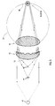
- FIG. 4A shows an intraocular lens 20, in accordance with a preferred embodiment of the invention, which is installed in place of the lens of an eye.
- Lens 20 is attached to the interior of the eye 21 by attachment means 23 which may include sutures or other attachment materials as are known in the art.
- Lens 20 is preferably a tri-focal lens which is operative to focus images from infinity 42, from a middle distance 44 and from a reading distance 46 onto an imaging surface which is typically a retinal surface 48 of the eye.
- Figs. 4B and 4C generally illustrate a posterior view and a radial cross section, respectively, of intraocular lens 20 constructed in accordance with a preferred embodiment of the present invention. As can be seen in Fig.
- lens 20 preferably includes a generally smooth, curved, anterior surface 22 and a preferably wavy posterior surface 24 having diffractive power.
- Surface 24 is preferably curved in accordance with a base reference surface 26 which, together with the surface 22, gives refractive focusing preferably equal to that required for focusing an image at middle distance 44 onto retinal surface 48.
- the height of surface 24 fluctuates with respect to reference surface 26, which corresponds to the average curvature of surface 24.
- This varying height is operative, in accordance with a preferred embodiment of the invention, to form a multi-focal diffractive lens whose diffractive focusing power is superimposed on the refractive focusing power of the lens to form a tri-focal lens which focuses objects from far-distances 42, mid-distances 44 and near-distances 46 onto retinal surface 48.
- the diffractive pattern is a locally periodic structure (which is periodic in r2, not in r) which affects the phase of incident light, resulting in a corresponding, transverse, locally periodic, relative-phase structure of the exiting wave front.
- each zone of the diffractive structure of the present invention is a substantially symmetric functions of r2 with respect to a series of symmetry circles 28.
- Symmetry circles 28, whose spacing is also typically a function of r2 are typically defined by a series of minima and maxima of the topographical height function along lens radius "r".
- the topographical height function is substantially constant along symmetry circles 28.
- the use of substantially two-sided, 30 and 32, periodic (in r2) profile with optical height difference between minima and maxima substantially different from ⁇ /2 creates two reciprocal dominant diffraction orders, namely a "+1" diffraction order and a "-1" diffraction order, in addition to a dominant undiffracted "0" order.
- These three dominant diffraction orders which are generated by surface 24 of lens 20, are operative to focus incident light in accordance with three different foci.
- the incident light energy can be distributed substantially evenly among the three diffraction orders. While the locally symmetric nature of a preferred topographical function results in a symmetric intensity distribution between orders "+1" and "-1", the relative intensities of those orders with respect to the "0" order may still be controlled by the amplitude of the function.
- Fig. 5 schematically illustrates the combined optical effect of a contact lens 25 in accordance with a preferred embodiment of the present invention and a human eye lens 40.
- lens 40 is assumed to be at a rest position and is assumed to be without adaptive capability, since the typical user of a trifocal lens has little focusing capability, so that multi-focal ability is primarily attributed to lens 25.
- Incident light "I" comes from objects 42, 44 and 46, which are located within a long distance range (typically infinity), an intermediate distance range and a short distance range (typically reading distance), respectively, from the user.
- the incident light is focused by the combined refractive optical power of lens 25, the diffractive optical power of surface 24, and the refractive power of eye lens 40 onto retina surface 48, forming thereon focused images 52, 54 and 56 which correspond to objects 42, 44 and 46, respectively.
- most of the incident energy is contained in the three diffraction orders generated by diffractive surface 24, while other diffraction orders carry a negligible amount of light energy. It has been shown, experimentally and theoretically, that diffractive surfaces constructed in accordance with preferred embodiments of the present invention have such high light transmission efficiencies that the light intensity carried by any of the three dominant diffraction orders is sufficient for human vision.
- the "+1", "-1" and "0" orders conventionally represent the primary convergent order, the primary divergent order and the undiffracted light, respectively.
- the refractive power of lens 20 (or lens 25), which is determined by the curvatures of surfaces 22 and 26, serves both as a base optical power for diffractive surface 24 and as a corrective optical element for lens 40 when the lens is a contact lens.
- the refractive optical power of lens 20 (Figs. 4A, 4C) is always convergent and generally speaking has the same convergence as the normal eye lens for focusing objects at middle distances onto the retina.
- light coming from objects at infinity is carried by the "-1" order, where the divergent nature of the "-1" diffractive order creates a virtual image of the infinite distance object at the middle distance wherein this virtual image is imaged on the retina by the refractive power of lens 20.
- the refractive optical power of lens 25 is also generally convergent in order to compensate for the divergent "-1" order generated by surface 24.
- light coming from objects 46 at the short distance range is formed by the "+1" order into a virtual image at a middle distance
- light from the intermediate range is passed unaltered by the "0" order
- light from the long distance range is formed by the "-1" order into an image at the middle distance. Consequently, lens 40 focuses all three middle distance images onto the same image plane, i.e., the retina, forming a triple focused image thereon. If the user is incapable of focusing parallel rays (i.e.
- surface 22 may be constructed so as to provide lens 25 with further, corrective, refractive power, in accordance with the diopter number correction needed by the specific user such that the combined refractive power of lenses 25 and 40 focuses a middle distance image at the retina.
- the contact lens is illustrated as having the diffractive surface facing the cornea, where the diffractive surface is generally constructed to adapt to the curvature of a user's cornea, the diffractive surface may be part of the anterior surface of the contact lens.
- Figs. 6 - 8C illustrate radial cross-sections of contact lenses or intraocular lenses constructed in accordance with preferred embodiments of the present invention.
- the preferred embodiments described hereinbelow are presented for illustrative purposes only and are not to be understood as limiting the scope of the present invention in any sense.
- Figs. 7A - 8A only the diffractive surface is shown for simplicity.
- Figs 8B and 8C only a short, more enlarged, portion of the diffractive surface cross-section is shown.
- Fig. 6 illustrates a radial cross section of a lens 60, whose diffractive surface 64 substantially follows a square-wave topographical height function with respect to a generally smooth, curved, base reference surface 65, in accordance with a preferred embodiment of the present invention.
- the square wave function defines rectangular protrusions 66 and rectangular recesses 68 which are separated by step downs 70 and step ups 72.
- reference surface 65 is generally constructed to adapt to the curvature of a user's cornea.
- the relative light intensities carried by the "+1", the "-1" and the “0” diffraction orders are generally controlled by the height "h” of steps 70 and 72 which determines the phase difference between light passing through protrusions 66 and light passing through recesses 68 close to any of steps 70 or 72, (i.e. the optical step) of the diffraction pattern.
- optimal light transmission efficiency for three foci is achieved when the optical height "h o " is substantially less than ⁇ /2, where ⁇ is the average or typical optical wavelength viewed with the lens.
- the optical height of the step is approximately 0.32 ⁇ and the duty cycle is 0.5, then the three refractive orders carry approximately even amount of light energy, with a total efficiency of about 86%. It is interesting to note that for a step type bi-focal lens the total efficiency is about 81%.
- the width of a cycle is preferably approximately ⁇ f/2r.
- a duty cycle of 0.26 should be used in order to achieve a substantially even distribution of light intensity between the three diffraction orders.
- the over all transmission efficiency obtained by such a lens is only approximately 66%.
- Fig. 7A illustrates a diffractive surface 95 on a radial cross section of a lens.
- Surface 95 substantially follows a trapezoidal-wave topographical height function with respect to the base reference surface, in accordance with another preferred embodiment of the present invention.
- Fig. 7A shows the cross-section as a function of r2.
- the function shown in Fig. 7B results. It is seen that the rising and falling portions of the function have a parabolic variation with r.
- the trapezoidal wave function defines trapezoidal protrusions 96 and trapezoidal recesses 98.
- the parameters which control the light intensities in this embodiment are: the phase delay (optical step) between protrusions 96 and recesses 98, and the radial distance "s" over which the surface topography gradually changes from recess to protrusion or vice versa.
- the present invention has shown that optimal results are achieved with an optical step which is smaller than ⁇ /2.
- a slope up (and down) 0.2 of the period and upper and lower plateau of 0.3 of the period an efficiency of approximately 92% was calculated, generating 30.7% of the total incident energy through each diffraction order.
- This surface topography is not only smoother than the surface of the square structure of Fig. 6 (all corners are more than 90 degree angles) but it is also more efficient.
- the width of a cycle is preferably approximately ⁇ f/2r.
- Figs. 7C shows a surface topographical function where surface optical height has a triangular variation with r2.
- the optimal optical height h o for such profiles are calculated as .579 ⁇ .
- the total efficiency is approximately 85%, with each of the three orders having an efficiency of approximately 28%.
- Fig. 8A illustrate a radial cross section of a lens constructed in accordance with one particularly preferred embodiment of the invention.
- the surface topography function of a diffractive surface 104 is a smooth surface and has no discontinuities in the first (or higher) derivatives of the function.
- the amplitude "A" defined by equation (3) provides optimal light transmission efficiency together with a substantially even energy distribution among the three diffraction orders.
- the over all transmission efficiency achieved by this diffraction topography is over 90%. While this is slightly lower than the efficiency calculated for the trapezoidal topography, considering the extremely smooth surface which is provided by the topography of Fig. 8A, this topography is very preferable.
- topographical optical height function of the diffractive surface of a lens constructed in accordance with the present invention is not limited to the functions described hereinabove.
- other topographical functions which can be determined by numerical methods, may prove to yield even more efficient results.
- any different function "F(r)" of "r” may be substituted in equation (1) to replace "k ⁇ r2".
- Equation (4) can be decomposed into: wherein "J m " indicates the Bessel function coefficient of order m. Each component of the sum in (5) represents the effect of a single diffraction order, wherein “ J m [2 ⁇ / ⁇ (n2- n1)A] " controls the relative amplitude of the component and "imF(r)" ("i” indicates the imaginary part of the exponential function) determines its phase. In order to achieve an even distribution between the three orders, it is sufficient that the "0" order amplitude is equal to the "+1" order amplitude, since orders "+1" and “-1" have the same amplitude (due to the symmetry of the Bessel coefficients).
- the rising and falling slopes "S" of the trapezoidal function illustrated in Figs. 7A and 7B are varied to achieve uneven, but highly efficient tri-modal diffraction.
- the rising slope is 0.132 of the period and the falling slope is 0.264 of the period (referenced to r2).
- the upper and lower plateau are each 0.302 of the period.
- the height of the trapezoid is 0.398 ⁇ .
- the period is constructed of two parts each of the general form of equation (1) except that, for a preferred embodiment of the invention, in the falling half cycle, the spatial frequency is increased so that the radial distance taken up by this portion is only 45% of the period. In the rising half cycle, the spatial frequency is decreased so that the function requires 55% of the cycle.
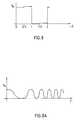
- the asymmetry is preferably achieved by adding an additional step over a portion, preferably half, of both the upper and lower portions of the topographical function (as shown in Fig. 9 as a function of r2).
- the large step h1 has an optical height 0.345 ⁇ with each of the smaller steps having an optical height of 0.05 ⁇ .
- the rising portion extends over 0.425 of the period and the falling portion extends over .575 of the period.
- the optical height is preferably .625 ⁇ .
- Fig. 8B illustrates a cross section of a portion of the diffractive surface 124 of a polynomial-topography lens constructed in accordance with a particularly preferred embodiment of the invention.
- Fig. 8C illustrates a cross-section of a portion of the diffractive surface 134 of a super-Gaussian-topography lens constructed in accordance with another particularly preferred embodiment of the invention.
- the surface topography functions describing the preferred surfaces of Figs. 8B and 8C are both smooth and have no discontinuities in the first (or higher) derivatives of the functions.
- the topographical optical height "h o (r)" with respect to a reference surface at a radial distance “r” from center “C” of the lens is a periodic function of r2.
- the topographical height, h o (u) with respect to a normalized periodic variable, u(r2+ ⁇ ) wherein ⁇ is a constant, is given by: wherein the a i coefficients are calculated using numerical optimization method.
- the variable "u”, which will be hereinafter referred to as the normalized periodic variable, is equal to zero at the beginning of each period of h o (r), and equal to 2 ⁇ at the end of each period.
- the a i s which are selected are those that yield a transmission efficiency distribution, among the diffraction orders, as close as possible to preselected target values chosen for the different orders. Any optimization method known in the art may be used to calculate the proper a i s.
- the surface topography illustrated in Fig. 8B will be hereinafter referred to as the polynomial surface topography.
- the function defining the outgoing wave front of the polynomial surface cannot be determined analytically by a procedure of the type used in equations (4) to (6). Therefore, the functional behavior of the outgoing wavefront must be determined numerically, preferably by using ray-tracing techniques, as is well known in the art.
- the following procedure is used to calculate the proper a i s: First, an order "n" is chosen for the polynomial function. Then, n arbitrary initial values are given to the n respective a i s. The transmission efficiencies of the dominant diffraction orders are then calculated, numerically, as discussed in the previous paragraph.
- the calculated efficiency of each of the dominant diffraction orders is subtracted from the corresponding preselected target value, yielding a respective efficiency error for each of the dominant orders.
- An error optimizing function such as the sum of the squares of the efficiency errors or any other desired function of the errors, is then constructed. Finally, the a i s are adjusted by a standard search procedure, such as "steepest slope", so that the value of the error optimizing function is reduced.
- the procedure described in the previous paragraph is preferably repeated until the value of the efficiency error optimizing function is below a preselected maximum value.
- the resultant surface topography function may be locally symmetric, typically when the target values represent an equal efficiency distribution among the participating orders, or locally asymmetric, when uneven target values are chosen.
- the topographical optical height "h o (r)" with respect to a reference surface at a radial distance “r” from center “C” of the lens is a periodic function of r2.
- the topographical height, "h o (u)” with respect to the periodic variable u(r2+ ⁇ ) is given by the formula: (8) H ⁇ exp ⁇ -[(u- ⁇ )/W] n ⁇ , wherein the parameters H, W and n are optimized using numerical optimization methods and wherein u is the normalized periodic variable, as explained above with reference to the embodiment of Fig. 8B.
- the super-Gaussian surface topography 8C will be hereinafter referred to as the super-Gaussian surface topography.
- an arbitrary order "n" is chosen for the super-Gaussian.
- the parameters H and W are then optimized, using numerical methods, to yield a preselected target efficiency distribution among the dominant orders. It should be appreciated that the numerical optimization procedure in this embodiment is relatively simple, because the super-Gaussian topography is completely determined by only three parameters.
- an asymmetric super Gaussian may be used.
- "u” is the normalized periodic variable defined above in equations (7) and (8).
- the parameters H, W1, W2, n1 and n2 are optimized using the numerical optimization methods described hereinabove.
- the diffractive surface of a contact lens may be at the posterior side, i.e. the side which faces the human eye cornea. This is possible due to the relatively smooth surfaces provided by preferred embodiments of the present invention, such as described hereinabove. However, it should be appreciated that in a variety of embodiments of the invention, each or both of the anterior and posterior surfaces may be appropriately constructed to have diffractive properties.
- the diffractive surface topography is much smoother than any of the prior art surfaces. More particularly, in preferred embodiments of the present invention, the radius of curvature of the diffractive surface at any point on the surface is equal to at least twice the step height (i.e. the difference in topographical height between the nearest local maximum and the nearest local minimum) and, more preferably, 10 to 100 times the step height.
- a contact lens 110 is a composite lens made up of a first portion 112, similar in structure to lens 25 and a second portion 114 having smooth anterior and posterior surfaces.
- An interior space 116 is preferably sealed from the outside by sealing the edges of portions 112 and 114 and generally contains air or a liquid having a refractive index substantially different from that of portions 112 and 114.
- the refractive power of the lenses may be the result of either portions 112 or 114 or both.
- the top of the diffractive surface touches the facing smooth surface of the facing portion, thereby spacing the two portions and forming a well defined optical structure.
- portions 112 and 114 are used for portions 112 and 114. More preferably, inner portion 112, facing the cornea, is formed of a relatively soft material which is convenient to the eye and portion 114 is formed of relatively hard material. In this preferred embodiment, the diffractive surface is preferably formed on the inner surface of portion 114, which is generally the more stable portion. The outside surface of portion 112 is adapted for contact with the cornea of an eye of a user.
- any of the multi-focal lenses described above may include at least one aspheric surface.
- the aspheric surface is operative to compensate for optical aberrations, which are typical of spherical surfaces, especially near the edge of the lens.
- the aspheric surface is the posterior surface of the lens and, more preferably, the posterior surface is shaped in accordance with the aspheric surface of the human cornea.
- the aspheric optical properties of the aspheric surface may be provided by refractive power, diffractive power or both. Aspheric properties can be added to the diffractive surface of the lens by shifting the radial locations of the optical steps on the surface, with respect to the normal (spherical) diffraction pattern, by precalculated amounts.
- the diameter of the lens is very small. Therefore, remembering that the diffractive surfaces are generally defined by locally periodic functions, the number of periods across the diameter may be very small (typically less than ten). In these cases, the performance of the lens may be affected by the phase of the locally periodic functions which define the surface topography.
- the phase ⁇ defined in equation (1) should not be arbitrary when the number of periods is small but, rather, it should be experimentally adjusted to yield optimal imaging efficiency. Such optimal efficiency depends on the application, but may provide for a greater proportion of the incident light going into one or two of the orders at the expense of the other(s).
Abstract
A tri-focal diffractive lens defining three foci, for viewing a band of light having a representative wavelength of λ, including a diffractive surface having a number of optical heights, ho, wherein the difference between the highest and the lowest optical heights is, modulo λ, substantially different from λ/2, wherein each of the foci receives at least 20% of light incident on the lens.
Description
- The present invention relates to multiple focus lenses in general and, more particularly, to multi-focal, diffractive, ophthalmic lenses.
- There are many applications for lenses which have more than one focal length. While there are important applications for multiple focus lenses in microscopes and other optical systems, the main effort spent in the development of multi-focal lenses is directed towards human vision correction, and especially towards construction of efficient multi-focal intraocular and contact lenses (collectively referred to herein as "ophthalmic lenses"). Since the fraction of incident light which is utilized by a multiple focal lens is divided between the different focal lengths, such lenses should be constructed to yield high light transmission efficiency. The need for such improved efficiency is particularly important for intraocular multi-focal lenses, since human vision is poor at low light levels.
- Generally speaking, there are two basic approaches to the design and construction of a multiple focal lens, namely, the spatial division approach and the multiple diffraction approach.
- Fig. 1, which is an anterior view illustration of a
multi-focal lens 10, shows a spatially divided lens. The lens is sectioned into discrete, adjacent,refractive sections 12 which are, normally, concentric. The non-adjacent sections are grouped into a number of groups (typically two), wherein each group corresponds to a single-focus refractive lens, and wherein each section is an optical equivalent of a portion of the corresponding lens. Thus, each group is a spatially discontinuous, single-focus, refractive lens. - Since all incident light passing through each refractive group is focused in accordance with only one, respective, focal length, the fraction of total incident energy focused in accordance with each focal length is, optimally, equal to the fractional area of incidence covered by the respective refractive group.
- To achieve good results in ophthalmic lenses, it is usually necessary that
lens 10 comprise a large number ofsections 12. If the lens is divided into a small number of concentric sections, the relative intensities of the different groups might vary in accordance with the expansion and contraction of the eye pupil. - U.S. Patent Nos. 4,162,122 and 4,210,391 are concerned with refractive contact lenses which are divided into many concentric annular sections, wherein any two adjacent sections belong to two different focal groups. An attempt to spatially divide a contact lens into non-concentric sections is described in U.S. Patent No. 4,704,016.
- As can be seen in Fig. 2, a
diffraction lens 14 is generally constructed in accordance with a diffractive pattern, i.e. a locally periodic structure which affects the phase and/or amplitude of incident light. This results in a corresponding, transverse, locally periodic, relative-phase structure of the exiting wave front, thereby producing a multi-order diffraction image. By properly constructing a variable-period diffractive pattern, a given diffraction order may be focused onto a respective image plane on which it constructively interferes. - It should be appreciated that the different foci of diffractive lenses do not correspond to different zones of
diffraction lens 14. Rather, every point oflens 14 diffracts the incident light into the different diffraction orders which correspond to the different foci. - A well known approach to the construction of diffractive patterns involves the use of Fresnel zone plates or Fresnel phase plates, which produce a variety of spherical wave fronts having different radii of curvature, wherein each radius corresponds to a different diffraction order. This general approach is described in "The Studies of Transmission Zone Plates", by Ora E. Myers, Jr., University of Colorado, Boulder, Colorado, 1951 and in "Elementary Diffraction Theory of Zone Plates", by Milton Sussman, American Optical Company, Instrument Division, Buffalo, New York, 1959.
- Prior art Fresnel phase plates have a typical general structure, which can be seen in Fig. 2, wherein the diffractive pattern comprises a series of one-way
optical steps 16.Optical steps 16 are defined by sharp drops "d" in lens thickness, which cause a proportional phase difference between adjacent light rays passing through opposite sides ofstep 16. Typically, for bifocal diffractive lenses, the phase delay caused by drop "d" in height ofsteps 16 is equal to one half of a design wavelength "λ" which is typical of the wavelengths viewed with the lens. It has been generally believed that best results are achieved when there are a large number of steps and when the drops are very sharp, because some of the incident energy would not, otherwise, be focused to either of the foci. - U.S. Patent Nos. 4,830,481 and 5,076,684 both describe such lenses. U.S. Patent 4,830,481 appears to suggest that the sharp drop "d" can be smoothed to a limited extent, by curving the sharp corners in accordance with a limited radius of curvature (specifically, not more than one or two times the step height), sacrificing just a small fraction of the incident energy. Nevertheless, this reference teaches that some sacrifice in efficiency is a result of such a "smoother" lens.
- A bifocal diffraction Raleigh Wood lens is used in the bifocal microscope described in "Bifocus Microscope" by V.P. Koronkevitch, V.N. Nagorni, I.G. Palchikova and A.G.Poleshchuk, Optik 78, No. 2, 1988, pp. 64-66. As can be seen in Fig.3, such a Raleigh
Wood lens 11 consists of a series ofrectangular protrusions 13 separated by a series ofrectangular recesses 15, wherein the width of each protrusions is substantially equal to the width of an adjacent recess, i.e. a duty-cycle of 0.5, and wherein the phase difference between the protrusions and the recesses, i.e. the step height, is approximately equal to λ/2(n₂-n₁), where λ is the typical wavelength used and n₁, n₂ are the refractive indices of the lens and the material outside the lens. The lens is described as having a light transmission efficiency of 81% divided equally between intense "-1" and "+1" diffraction orders, whereas other orders are negligible. This lens has a topographical structure which is periodic in r². - There have also been attempts to construct a contact lens which combines advantageous features of both the spatial division and the diffraction order approaches. A lens can be spatially divided into narrow refractive concentric sections which are also diffractive phase-shift plates, spaced by precalculated distances, such that some diffraction order foci coincide with the refractive foci. Examples of such combinations is described in U.S. Patent Nos. 4,338,005, 4,340,283, and 4,881,805, all issued to Cohen.
- Considerable efforts have been directed toward controlling the relative intensities of the different orders in bi-focal lenses, by proper engineering of the diffractive structure, so that most of the incident energy is utilized by the orders which create the desired foci. Still, existing diffraction lenses having more than two foci and/or featuring a distinctively uneven distribution of light between the foci do not yield high light transmission efficiencies.
- Moreover, the surfaces of the more efficient of the currently available bi-focal ophthalmic lenses (refractive, diffractive or hybrid) include a series of sharp edged steps, which define a plurality of sharp corners. The sharp edges and corners present inevitable difficulties for the user of the lens. First, dirt which is easily collected at the sharp corners is extremely difficult to remove by conventional cleaning instruments and materials. Secondly, the edges of the optical steps can cause undesirable light interference, known as glare, which appear to the eye of the user as disturbing blurry intense light. Thirdly, the sharp edged surface can cause uncomfortable irritation to the eyes of the user when the lens is used as a contact lens.
- At present, only bi-focal ophthalmic lenses featuring a substantially even distribution of light between their two foci are available. This limitation is especially critical for intraocular lenses where the eye itself has no focusing power. With two focal lengths, the user is often deprived of clear vision in the mid range. There is therefore a need for an efficient intraocular lens having more than two focal lengths. Also, uneven intensity distribution between the foci may be desired such that vision of a preselected distance ranges will be particularly enhanced. For example, reading may require higher transmission efficiency than the efficiency required for viewing landscapes due to the generally different available light intensities.
- U.S. Patents 5,117,306; 5,121,980 and 5,120,120 to Cohen, describe various forms of bi-focal lenses.
- The present invention provides improved solutions to the above mentioned problems associated with ophthalmic multi-focal diffractive lenses. A lens constructed and operative in accordance with a preferred embodiment of the present invention effectively focuses incident light in accordance with two or more different focal lengths simultaneously, and maintains an over all light transmission efficiency for more than two foci which is generally comparable with and often substantially better than bi-focal diffraction lenses. The high total light transmission efficiency is substantially maintained, in a preferred embodiment of the invention, regardless of whether the incident light is distributed evenly or unevenly among the different foci.
- The present invention also provides an extremely efficient ophthalmic multi-focal diffractive lens having a preselected number of dominant foci and having a preselected distribution of incident light among the different foci. The preselected distribution may be even or uneven.
- Surprisingly, the other problems of many existing ophthalmic lenses, namely those associated with a sharp stepped surface, are also solved by the present invention. The surfaces of a lens constructed and operative in accordance with a preferred embodiment of the invention are extremely smooth compared to those of most known diffraction and refraction multi-focal ophthalmic lenses.
- In accordance with one preferred embodiment of the present invention there is thus provided a lens including a diffractive surface. The diffractive surface is constructed so that its radial cross-section is shaped in accordance with a diffractive pattern which diffracts most of the incident light energy into three dominant diffraction orders, namely, "-1", "0" and "+1". The "+1", "0" and "-1" diffraction orders conventionally represent convergingly diffracted light, divergingly diffracted light and undiffracted light, respectively. In a preferred embodiment, the incident energy is distributed substantially evenly among the three orders so that each of the three orders carries approximately one third of the transmitted energy.
- In another preferred embodiment of the invention, the amount of light in the orders is not equal so as to account for the normal lighting conditions of objects at different distance ranges.
- In lenses having even or uneven division of light, a substantial proportion of the total light is directed into each of the orders and, hence, the contrast at each of the foci is high. In accordance with a preferred embodiment, the dominant diffraction orders are preselected and the distribution of light among the dominant orders is preset.
- A lens constructed in accordance with a preferred embodiment of the present invention is further provided with refractive power. The surfaces of the lens are appropriately constructed so that undiffracted incident light coming to the lens from a preset distance, which is preferably within an intermediate distance range (i.e. more than reading distance and less than infinity), is refractively focused (with the possible aid of the natural lens and/or cornea of the human eye) onto a given image plane (typically, a human eye retina).
- In accordance with a preferred embodiment of the invention, light from the preset distance defined by the refractive surface is carried onto the image plane by the "0" order, which represents light which is unaffected by the diffractive surface. The "-1" order, representing light which is diverged by the diffractive surface, focuses light from a longer range (typically infinity) onto the same image plane. The "+1" order, representing light which is converged by the diffractive surface, focuses light from a shorter range (typically reading distance) onto the same image plane.
- In accordance with a preferred embodiment of the invention, the topographical height at any given point on the diffractive surface (i.e. the separation of a given point on the diffractive surface with respect to a base reference surface corresponding to the general curvature of the diffractive surface) is generally a smooth, essentially periodic, function, h, of a function, u(r), of the radial coordinate, r. Furthermore, each period of this periodic function of u(r) is essentially symmetric with respect to u(r). Thus, the periodic function defines gradual, generally symmetric, rising and falling slopes between generally smooth peaks.
- This periodic topographical height function "h", defines an optical height function "ho" which is equal to "h" multiplied by (n₂-n₁), where n₂ and n₁ are the refractive indices of the lens material and the surrounding medium (typically air, eye tears of the intraocular fluid), respectively.
- In accordance with particularly preferred embodiments of the invention the optical height function is different from λ/2, modulo λ.
- In an alternative preferred embodiment of the invention the optical height function is a periodic function, ho, of a function, u(r), of the radial coordinate but the function, ho, is not symmetric. That is to say, during one portion of the period the function of the radial coordinate is different from that in a second portion of the period. More preferably, the spatial frequency of one portion is greater than that of the second portion.
- In one embodiment of the present invention, the surface topographical function, h, defines essentially rectangular protrusions which are separated by essentially rectangular recesses. The step height of the protrusions determines the absolute intensity of each order as well as the relative intensities among the three diffraction orders. By properly selecting the height and optionally adjusting the "duty cycle" of the recesses (the proportion of the spatial cycle at during which there is protrusion), it is possible to equally divide the diffracted energy among the three orders, maintaining a reasonable imaging efficiency of close to 29% (i.e. image to background light intensity ratio) in each order, for a total of 86%. Furthermore, a high efficiency can be maintained for uneven distributions as well. Generally speaking, the optical height of the step is substantially less than λ/2.
- In another embodiment of the invention, the diffractive surface follows a trapezoidal wave topographical pattern. The computed imaging efficiency obtained by this embodiment is 92.1%.
- In one particularly preferred embodiment of the invention, the topographical optical height, ho, of any given point on the diffractive surface of the lens, follows the formula:

- Numerical analysis of the formula which is presented in the previous paragraph shows that optimal efficiency is achieved when the following parameters are used:


- For desired uneven distributions among the three orders, additional smaller steps are preferably added to the rectangular profiles, the slopes of the trapezoids are made unequal for the "rising" and "falling" portions and, for the sinusoidal function, the sinusoidal frequency is made different for two portions of the period.
- In a accordance with another particularly preferred embodiment of the invention, the topographical optical height of the surface follows a generally periodic function of the radial coordinate, wherein each period of the periodic function follows the polynomial function:

wherein u (0≦u≦2π) is the normalized periodic variable (i.e u is reset to zero at the beginning of each period of the periodic function) and wherein the ais are calculated using numerical optimization methods. Preferably, the radial width of a given period of the periodic function is inversely proportional to r², wherein "r" is the radial distance between the center of the given period and the center of the lens. By proper application of the numerical optimization methods, the transmission efficiency of each of the dominant diffraction orders is brought to a preselected target value. The resultant topographical function may be locally symmetric, typically when the target values represent an even efficiency distribution among the participating orders, or locally asymmetric, when the target values are uneven. - In accordance with yet another particularly preferred embodiment of the invention, each period of the topographical optical height function follows a "super Gaussian" function of the form:

- Alternatively, for an asymmetric distribution of transmission efficiencies, an asymmetric super Gaussian of the form:


is used. In this preferred embodiment of the invention H, W₁, W₂, n₁ and n₂ are optimized using numerical optimization methods. u₀ is equal to
- In a preferred embodiment of the present invention, the lens includes an aspheric surface. The aspheric surface is operative to compensate for optical aberrations which are typical of spherical optics. In a preferred embodiment, the posterior surface of the lens is the aspheric surface and, more preferably, the posterior surface is constructed to precisely fit the aspheric surface of the human cornea. In a preferred embodiment, the aspheric optical properties of the aspheric surface are provided by refractive power, diffractive power or both.
- A multi-focal contact lens constructed in accordance with a preferred embodiment of the present invention has such a smooth diffractive surface that, even when being in contact with the cornea, does not generally irritate the eye of the user. Therefore, it is possible that the posterior surface, i.e. the surface facing the human eye cornea, of such a contact lens may possess diffractive properties. Alternatively, it is possible that the anterior surface of the lens is diffractive.
- In another preferred embodiment of the invention, the diffractive surface may be an interior surface of a sandwich lens structure. Preferably, such a sandwich lens is formed of two portions having respectively facing surfaces, at least one of which being diffractive. More preferably, the two portions of the sandwich lens have different refractive indices and neither of the external (i.e. not interfacing) surfaces of the two portions are diffractive. In a particularly preferred variant of this embodiment, especially useful for contact lenses, the outer portion is formed of a relatively hard material and the inner portion (next to the cornea) is formed of a relatively soft material.
- In addition to their ophthalmic applications, multi-focal diffraction lenses constructed in accordance with preferred embodiments of the present invention can be used in various other multi-focal optical systems. Such multi-focal systems include, for example, multi-focal microscopes.
- In a general aspect, the invention provides a tri-focal lens having a distribution among at least three dominant diffraction orders, wherein the efficiency of each dominant order is not lower than 20% and the sum of the efficiencies of all the dominant orders is at least 60% and more preferably over 80%.
- In another general aspect, the invention provides a multi-focal diffractive lens including a diffractive surface, having a surface topography which includes local minima and maxima, operative to focus light in accordance with a plurality of dominant diffraction orders defining a plurality of respective foci, wherein the imaging efficiency of each of the orders is not less than twenty percent and wherein the radius of curvature of the diffractive surface, at any given point on the surface, is equal to at least twice the difference in topographical height between the local minimum nearest to the given point and the local maximum nearest to the given point. In a preferred embodiment of the invention, the radius of curvature at any point on the surface is equal to at least 10 or, more preferably, at least 50 to 100 times the difference in topographical height between the nearest local minimum and the nearest local maximum.
- The present invention will be better understood from the following description of the preferred embodiments together with the following drawings of which:
- Fig. 1 is a transverse illustration of a prior art multi-focal refractive lens;
- Fig. 2 is a radial, cross-sectional, illustration of a prior art bifocal diffractive lens;
- Fig. 3 is a radial, cross-sectional, illustration of a prior art Raleigh-Wood lens;
- Fig. 4A is a schematic illustration of the optical effect of an intraocular lens in accordance with a preferred embodiment of the present invention;
- Fig. 4B is posterior view illustration of an intraocular lens constructed in accordance with preferred embodiments of the present invention;
- Fig. 4C is a radial, cross-sectional, illustration of the lens of Fig. 4A;
- Fig. 5 is a schematic illustration of the optical effect of a contact lens in accordance with a preferred embodiment of the present invention when the lens is juxtaposed with a human eye lens;
- Fig. 6 is a radial, cross-sectional, illustration of a lens having a square wave diffractive surface topography, plotted as a function of r, the radial dimension, in accordance with a preferred embodiment of the invention;
- Fig. 7A is a radial, cross-sectional, illustration of the diffractive surface of a lens having a trapezoidal diffractive surface topography when plotted as a function of r², in accordance with a preferred embodiment of the invention;
- Fig. 7B is a radial, cross-sectional, illustration of the true topography of the lens of Fig. 7A plotted as a function of r, the actual radial dimension, in accordance with a preferred embodiment of the invention;
- Fig. 7C is a radial, cross-sectional, illustration of the diffractive surface of a lens having a triangular diffractive surface topography when plotted as a function of r², in accordance with a preferred embodiment of the invention;
- Fig. 7D is a radial, cross-sectional, illustration of the true topography of the lens of Fig. 7C plotted as a function of r, the actual radial dimension, in accordance with a preferred embodiment of the invention;
- Fig. 8A is a radial, cross-sectional, illustration of the diffractive surface of a lens having a diffractive surface topography which follows a particular formula in accordance with one particularly preferred embodiment of the invention;
- Fig. 8B is a radial, cross-sectional, illustration of part of the diffractive surface of a lens having a diffractive surface topography which follows a particular formula in accordance with another preferred embodiment of the invention;
- Fig. 8C is a radial, cross-sectional, illustration of part of the diffractive surface of a lens having a diffractive surface topography which follows a particular formula in accordance with yet another preferred embodiment of the invention;
- Fig. 9 is a detail of one cycle of the diffractive surface of a square wave type diffraction lens of the present invention, adapted for uneven division of light between three dominant diffraction orders; and
- Fig. 10A and 10B show two sandwich type contact lens forms of the present invention.
- Reference is now made to Fig. 4A which shows an
intraocular lens 20, in accordance with a preferred embodiment of the invention, which is installed in place of the lens of an eye.Lens 20 is attached to the interior of theeye 21 by attachment means 23 which may include sutures or other attachment materials as are known in the art.Lens 20 is preferably a tri-focal lens which is operative to focus images frominfinity 42, from amiddle distance 44 and from areading distance 46 onto an imaging surface which is typically aretinal surface 48 of the eye. Figs. 4B and 4C generally illustrate a posterior view and a radial cross section, respectively, ofintraocular lens 20 constructed in accordance with a preferred embodiment of the present invention. As can be seen in Fig. 4C,lens 20 preferably includes a generally smooth, curved,anterior surface 22 and a preferably wavyposterior surface 24 having diffractive power.Surface 24 is preferably curved in accordance with abase reference surface 26 which, together with thesurface 22, gives refractive focusing preferably equal to that required for focusing an image atmiddle distance 44 ontoretinal surface 48. - The height of
surface 24 fluctuates with respect toreference surface 26, which corresponds to the average curvature ofsurface 24. This varying height is operative, in accordance with a preferred embodiment of the invention, to form a multi-focal diffractive lens whose diffractive focusing power is superimposed on the refractive focusing power of the lens to form a tri-focal lens which focuses objects from far-distances 42, mid-distances 44 and near-distances 46 ontoretinal surface 48. - In accordance with a preferred embodiment of the invention, the diffractive pattern is a locally periodic structure (which is periodic in r², not in r) which affects the phase of incident light, resulting in a corresponding, transverse, locally periodic, relative-phase structure of the exiting wave front. In contrast to prior art non-rectangular diffractive patterns, which typically consist of a series of one sided optical steps (as demonstrated in Fig. 2), each zone of the diffractive structure of the present invention is a substantially symmetric functions of r² with respect to a series of symmetry circles 28. Symmetry circles 28, whose spacing is also typically a function of r², are typically defined by a series of minima and maxima of the topographical height function along lens radius "r". The topographical height function is substantially constant along symmetry circles 28. The use of substantially two-sided, 30 and 32, periodic (in r²) profile with optical height difference between minima and maxima substantially different from λ/2 creates two reciprocal dominant diffraction orders, namely a "+1" diffraction order and a "-1" diffraction order, in addition to a dominant undiffracted "0" order. These three dominant diffraction orders, which are generated by
surface 24 oflens 20, are operative to focus incident light in accordance with three different foci. By a suitable choice of the topographical function ofsurface 24, the incident light energy can be distributed substantially evenly among the three diffraction orders. While the locally symmetric nature of a preferred topographical function results in a symmetric intensity distribution between orders "+1" and "-1", the relative intensities of those orders with respect to the "0" order may still be controlled by the amplitude of the function. - It should be appreciated that it is possible, in an alternative preferred embodiment of the invention to achieve an uneven distribution between orders "+1" and "-1" by using a topographical function in which the two
sides - Reference is now made to Fig. 5, which schematically illustrates the combined optical effect of a
contact lens 25 in accordance with a preferred embodiment of the present invention and ahuman eye lens 40. In determining the desired refractive focal length oflens 25,lens 40 is assumed to be at a rest position and is assumed to be without adaptive capability, since the typical user of a trifocal lens has little focusing capability, so that multi-focal ability is primarily attributed tolens 25. Incident light "I" comes fromobjects lens 25, the diffractive optical power ofsurface 24, and the refractive power ofeye lens 40 ontoretina surface 48, forming thereon focused images 52, 54 and 56 which correspond toobjects - In a preferred embodiment of the invention, most of the incident energy is contained in the three diffraction orders generated by
diffractive surface 24, while other diffraction orders carry a negligible amount of light energy. It has been shown, experimentally and theoretically, that diffractive surfaces constructed in accordance with preferred embodiments of the present invention have such high light transmission efficiencies that the light intensity carried by any of the three dominant diffraction orders is sufficient for human vision. The "+1", "-1" and "0" orders conventionally represent the primary convergent order, the primary divergent order and the undiffracted light, respectively. - The refractive power of lens 20 (or lens 25), which is determined by the curvatures of
surfaces diffractive surface 24 and as a corrective optical element forlens 40 when the lens is a contact lens. - The refractive optical power of lens 20 (Figs. 4A, 4C) is always convergent and generally speaking has the same convergence as the normal eye lens for focusing objects at middle distances onto the retina. In accordance with a preferred embodiment of the invention, light coming from objects at infinity is carried by the "-1" order, where the divergent nature of the "-1" diffractive order creates a virtual image of the infinite distance object at the middle distance wherein this virtual image is imaged on the retina by the refractive power of
lens 20. Light from short (typically reading) distances is carried by the "+1" (convergent) order, that creates a virtual image of the short distance object at the middle distance, wherein this virtual image is imaged on the retina by the refractive power oflens 20 and light from the intermediate range is carried by the "0" (non-focusing) order and is imaged on the retina by the refractive power oflens 20. - For contact lenses, the refractive optical power of
lens 25 is also generally convergent in order to compensate for the divergent "-1" order generated bysurface 24. In accordance with a preferred embodiment of the invention, light coming fromobjects 46 at the short distance range (typically reading distance) is formed by the "+1" order into a virtual image at a middle distance, light from the intermediate range is passed unaltered by the "0" order and light from the long distance range is formed by the "-1" order into an image at the middle distance. Consequently,lens 40 focuses all three middle distance images onto the same image plane, i.e., the retina, forming a triple focused image thereon. If the user is incapable of focusing parallel rays (i.e. a near sighted user) or is farsighted,surface 22 may be constructed so as to providelens 25 with further, corrective, refractive power, in accordance with the diopter number correction needed by the specific user such that the combined refractive power oflenses - Reference is now made to Figs. 6 - 8C, which illustrate radial cross-sections of contact lenses or intraocular lenses constructed in accordance with preferred embodiments of the present invention. The preferred embodiments described hereinbelow are presented for illustrative purposes only and are not to be understood as limiting the scope of the present invention in any sense. For Figs. 7A - 8A only the diffractive surface is shown for simplicity. For Figs 8B and 8C, only a short, more enlarged, portion of the diffractive surface cross-section is shown.
- Reference is made to Fig. 6, which illustrates a radial cross section of a
lens 60, whosediffractive surface 64 substantially follows a square-wave topographical height function with respect to a generally smooth, curved,base reference surface 65, in accordance with a preferred embodiment of the present invention. The square wave function definesrectangular protrusions 66 andrectangular recesses 68 which are separated bystep downs 70 and step ups 72. In contact lenses,reference surface 65 is generally constructed to adapt to the curvature of a user's cornea. The relative light intensities carried by the "+1", the "-1" and the "0" diffraction orders are generally controlled by the height "h" ofsteps protrusions 66 and light passing throughrecesses 68 close to any ofsteps protrusions 66 and width "V" of the total cycle. - In accordance with the present embodiment, contrary to what has been generally believed in the past for bifocal square protrusion lenses, optimal light transmission efficiency for three foci is achieved when the optical height "ho" is substantially less than λ/2, where λ is the average or typical optical wavelength viewed with the lens.
- According to a preferred embodiment of the invention when the optical height of the step is approximately 0.32λ and the duty cycle is 0.5, then the three refractive orders carry approximately even amount of light energy, with a total efficiency of about 86%. It is interesting to note that for a step type bi-focal lens the total efficiency is about 81%. The width of a cycle is preferably approximately λf/2r.
- According to an alternate embodiment of the present invention, when the optical step determined by
steps - Reference is now made to Fig. 7A, which illustrates a
diffractive surface 95 on a radial cross section of a lens.Surface 95 substantially follows a trapezoidal-wave topographical height function with respect to the base reference surface, in accordance with another preferred embodiment of the present invention. Fig. 7A shows the cross-section as a function of r². When the function is plotted as a function of r, which is true radial distance, the function shown in Fig. 7B results. It is seen that the rising and falling portions of the function have a parabolic variation with r. The trapezoidal wave function definestrapezoidal protrusions 96 and trapezoidal recesses 98. The parameters which control the light intensities in this embodiment are: the phase delay (optical step) betweenprotrusions 96 and recesses 98, and the radial distance "s" over which the surface topography gradually changes from recess to protrusion or vice versa. Again, the present invention has shown that optimal results are achieved with an optical step which is smaller than λ/2. Using an optical height of .369λ, a slope up (and down) 0.2 of the period and upper and lower plateau of 0.3 of the period, an efficiency of approximately 92% was calculated, generating 30.7% of the total incident energy through each diffraction order. This surface topography is not only smoother than the surface of the square structure of Fig. 6 (all corners are more than 90 degree angles) but it is also more efficient.The width of a cycle is preferably approximately λf/2r. - Figs. 7C shows a surface topographical function where surface optical height has a triangular variation with r². The same function, plotted is true (r) space, has the shape shown in Fig. 7D, where the rising and falling portions both have parabolic shapes. The optimal optical height ho for such profiles are calculated as .579λ. For this embodiment the total efficiency is approximately 85%, with each of the three orders having an efficiency of approximately 28%.
- Reference is now made to Fig. 8A, which illustrate a radial cross section of a lens constructed in accordance with one particularly preferred embodiment of the invention. Unlike any of the previous embodiments described hereinabove, the surface topography function of a diffractive surface 104 is a smooth surface and has no discontinuities in the first (or higher) derivatives of the function. According to this preferred embodiment, the topographical optical height "ho(r)" with respect to a reference surface at a radial distance "r" from center "C" of the lens is given by the formula:


"λ" is the wavelength of light at the center of the typical bandwidth which is viewed with the lens (typically in the visible spectrum), "f" is the desired first order focal length, and φ is an arbitrary constant. - By using conventional mathematical methods, it has been shown that for a function such as equation (1), the amplitude "A" defined by equation (3) provides optimal light transmission efficiency together with a substantially even energy distribution among the three diffraction orders. The over all transmission efficiency achieved by this diffraction topography is over 90%. While this is slightly lower than the efficiency calculated for the trapezoidal topography, considering the extremely smooth surface which is provided by the topography of Fig. 8A, this topography is very preferable.
- It should be appreciated that the topographical optical height function of the diffractive surface of a lens constructed in accordance with the present invention is not limited to the functions described hereinabove. In fact, other topographical functions, which can be determined by numerical methods, may prove to yield even more efficient results. For example, any different function "F(r)" of "r" may be substituted in equation (1) to replace "k·r²". The value of "A" can then be calculated in the following manner [the same procedure was used to determine the value of equation (3)]:
First, it is known that a function of the form

wherein "λ" is the center of the typical bandwidth which is viewed with the lens (typically in the visible spectrum), "n₁" is the refractive index of the lens and "n₂" is the refractive index of the surrounding medium. Equation (4) can be decomposed into:
wherein "Jm" indicates the Bessel function coefficient of order m. Each component of the sum in (5) represents the effect of a single diffraction order, wherein "

Equation (6) can be solved by numerical methods in order to obtain the optimal value of "A". - It should be noted that by selecting a different value of amplitude "A", the "0" order can be almost completely suppressed so that all the incident energy is divided between orders "+1" and "-1", thereby an efficient bi-focal lens can be achieved. Also, any other value of "A" may be selected in order to achieve other desired energy distributions between order "0" and orders "±1". Furthermore, by biasing the local symmetry of the topographical function, the relative intensities of orders "+1" and "-1" can be also continuously varied.
- In adapting the diffractive lenses thus far described to uneven, high efficiency distributions of the incident light between the three orders, it has been found that changing the symmetry of the surface topographical function results in the following typical preferred embodiments of the invention.
- For example in one preferred embodiment of the invention, the rising and falling slopes "S" of the trapezoidal function illustrated in Figs. 7A and 7B are varied to achieve uneven, but highly efficient tri-modal diffraction. In one particular embodiment the rising slope is 0.132 of the period and the falling slope is 0.264 of the period (referenced to r²). The upper and lower plateau are each 0.302 of the period. The height of the trapezoid is 0.398λ. For this embodiment the calculated energy distribution between the three orders is order "0"=0.240, order "+1"=0.271 and order "-1"=0.390 for a total efficiency of about 90%. This distribution is believed to be better suited for matching with the light levels generally available for different tasks than is the even distribution. Other distributions are of course possible with other choices of "S" and optical height.
- With the sinusoidal profile, the period is constructed of two parts each of the general form of equation (1) except that, for a preferred embodiment of the invention, in the falling half cycle, the spatial frequency is increased so that the radial distance taken up by this portion is only 45% of the period. In the rising half cycle, the spatial frequency is decreased so that the function requires 55% of the cycle. For this embodiment the calculated energy distribution between the three orders is order "0"=0.234, order "+1"=0.288 and order "-1"=0.350 for a total efficiency of 87.2%.
- For the rectangular embodiment, the asymmetry is preferably achieved by adding an additional step over a portion, preferably half, of both the upper and lower portions of the topographical function (as shown in Fig. 9 as a function of r²). For a particular preferred embodiment of the invention, the large step h₁ has an optical height 0.345λ with each of the smaller steps having an optical height of 0.05λ. For this embodiment the calculated energy distribution between the three orders is order "0"=0.217, order "+1"=0.267 and order "- 1"=0.366 for a total efficiency of 85%.
- For a preferred triangular profile the rising portion extends over 0.425 of the period and the falling portion extends over .575 of the period. The optical height is preferably .625λ. For this embodiment the energy distribution between the three orders is order "0"=0.215, order "+1"=0.238 and order "-1"=0.353 for a total efficiency of 80.6%.
- It must be remembered that all of the radial distances are scaled to r² and not to r.
- Reference is now made to Figs. 8B and 8C, which relate to additional, particularly preferred, embodiments of the present invention. Fig. 8B illustrates a cross section of a portion of the
diffractive surface 124 of a polynomial-topography lens constructed in accordance with a particularly preferred embodiment of the invention. Fig. 8C illustrates a cross-section of a portion of thediffractive surface 134 of a super-Gaussian-topography lens constructed in accordance with another particularly preferred embodiment of the invention. As in the embodiment of Fig. 8A, the surface topography functions describing the preferred surfaces of Figs. 8B and 8C are both smooth and have no discontinuities in the first (or higher) derivatives of the functions. - In the embodiment of Fig. 8B, the topographical optical height "ho(r)" with respect to a reference surface at a radial distance "r" from center "C" of the lens is a periodic function of r². within each period of ho(r), the topographical height, ho(u), with respect to a normalized periodic variable, u(r²+δ) wherein δ is a constant, is given by:

wherein the ai coefficients are calculated using numerical optimization method. The variable "u", which will be hereinafter referred to as the normalized periodic variable, is equal to zero at the beginning of each period of ho(r), and equal to 2π at the end of each period. As in the In accordance with a preferred embodiment of the invention, the ais which are selected are those that yield a transmission efficiency distribution, among the diffraction orders, as close as possible to preselected target values chosen for the different orders. Any optimization method known in the art may be used to calculate the proper ais. The surface topography illustrated in Fig. 8B will be hereinafter referred to as the polynomial surface topography. - It is appreciated that, contrary to the sinusoidal embodiment of Fig. 8A, the function defining the outgoing wave front of the polynomial surface cannot be determined analytically by a procedure of the type used in equations (4) to (6). Therefore, the functional behavior of the outgoing wavefront must be determined numerically, preferably by using ray-tracing techniques, as is well known in the art. In a preferred embodiment of the invention, the following procedure is used to calculate the proper ais:
First, an order "n" is chosen for the polynomial function. Then, n arbitrary initial values are given to the n respective ais. The transmission efficiencies of the dominant diffraction orders are then calculated, numerically, as discussed in the previous paragraph. Then, the calculated efficiency of each of the dominant diffraction orders is subtracted from the corresponding preselected target value, yielding a respective efficiency error for each of the dominant orders. An error optimizing function, such as the sum of the squares of the efficiency errors or any other desired function of the errors, is then constructed. Finally, the ais are adjusted by a standard search procedure, such as "steepest slope", so that the value of the error optimizing function is reduced. - The procedure described in the previous paragraph is preferably repeated until the value of the efficiency error optimizing function is below a preselected maximum value. The resultant surface topography function may be locally symmetric, typically when the target values represent an equal efficiency distribution among the participating orders, or locally asymmetric, when uneven target values are chosen.
- For a polynomial of degree six (n=6), as an example, wherein a₁=3.17·10⁻², a₂=0.17, a₃=-0.03, a₄=-1.53·10⁻², a₅=4.29·10⁻³ and a₆=-2.86·10⁻⁴, efficiencies of 30.5%, 30% and 30%, were calculated for the "0", "+1" and "-1" diffraction orders, respectively. It should be appreciated that this high transmission efficiency (a total efficiency of 90.5%) may be further increased by careful search of proper ais and/or by selecting a different polynomial order "n".
- By proper choice of the ais, it is also possible to produce uneven efficiency distributions. For example, when n=6, a₁=-8.43·10⁻³, a₂=-8.46·10⁻², a₃=0.13, a₄=-3.85·10⁻², a₅=4.13·10⁻³ and a₆=-1.32·10⁻⁴, the resultant efficiencies are 22%, 30% and 35%, for the "0", "+1" and "-1" diffraction orders, respectively. The total efficiency of this embodiment is 87%. It should be appreciated that other choices of ais may yield a higher efficiency.
- In the embodiment of Fig. 8C, the topographical optical height "ho(r)" with respect to a reference surface at a radial distance "r" from center "C" of the lens is a periodic function of r². Within each period of ho(r), the topographical height, "ho(u)", with respect to the periodic variable u(r²+δ) is given by the formula:

wherein the parameters H, W and n are optimized using numerical optimization methods and wherein u is the normalized periodic variable, as explained above with reference to the embodiment of Fig. 8B. The surface topography illustrated in Fig. 8C will be hereinafter referred to as the super-Gaussian surface topography. In this embodiment, as in the polynomial embodiment, an arbitrary order "n" is chosen for the super-Gaussian. The parameters H and W are then optimized, using numerical methods, to yield a preselected target efficiency distribution among the dominant orders. It should be appreciated that the numerical optimization procedure in this embodiment is relatively simple, because the super-Gaussian topography is completely determined by only three parameters. - For example, an efficient equal distribution between three diffraction orders is achieved with a super-Gaussian topography in which H=0.38 W=0.55π and n=4. The transmission efficiencies of the "0", "+1" and "-1" diffraction orders, in this embodiment, are 30.9%, 30.8% and 39.8%, respectively, for a total of 92.5%.
- Alternatively, for an asymmetric distribution of transmission efficiencies, an asymmetric super Gaussian may be used. The asymmetric Super-Gaussian follows the formula:


wherein
- For example, an efficient unequal distribution between three diffraction orders is achieved with an asymmetric Super-Gaussian topography in which H=0.406, W₁=0.44π, W₂=0.64π and n₁=n₂=4. The transmission efficiencies of the "0", "+1" and "-1" diffraction orders, in this embodiment, are 26%, 29% and 36%, respectively, for a total transmission efficiency of 92%.
- It should be appreciated that, due to the relatively few parameters used by the super-Gaussian and the relatively well-behaved response of the Gaussian to changes in the parameters, the relative efficiencies of the dominant diffraction orders can be accurately controlled.
- It is a feature of certain embodiments of the present invention that the diffractive surface of a contact lens may be at the posterior side, i.e. the side which faces the human eye cornea. This is possible due to the relatively smooth surfaces provided by preferred embodiments of the present invention, such as described hereinabove. However, it should be appreciated that in a variety of embodiments of the invention, each or both of the anterior and posterior surfaces may be appropriately constructed to have diffractive properties.
- It should be appreciated that in many preferred embodiments of the present invention, particularly in the embodiments described with reference to Figs. 8A-8C, the diffractive surface topography is much smoother than any of the prior art surfaces. More particularly, in preferred embodiments of the present invention, the radius of curvature of the diffractive surface at any point on the surface is equal to at least twice the step height (i.e. the difference in topographical height between the nearest local maximum and the nearest local minimum) and, more preferably, 10 to 100 times the step height.
- In further preferred embodiments of the invention, illustrated in Figs. 10A and 10B, a
contact lens 110 is a composite lens made up of afirst portion 112, similar in structure tolens 25 and asecond portion 114 having smooth anterior and posterior surfaces. Aninterior space 116 is preferably sealed from the outside by sealing the edges ofportions portions portions - In a preferred embodiment of the invention, two different materials are used for
portions inner portion 112, facing the cornea, is formed of a relatively soft material which is convenient to the eye andportion 114 is formed of relatively hard material. In this preferred embodiment, the diffractive surface is preferably formed on the inner surface ofportion 114, which is generally the more stable portion. The outside surface ofportion 112 is adapted for contact with the cornea of an eye of a user. - In accordance with a preferred embodiment of the present invention, any of the multi-focal lenses described above may include at least one aspheric surface. The aspheric surface is operative to compensate for optical aberrations, which are typical of spherical surfaces, especially near the edge of the lens. In a preferred embodiment, the aspheric surface is the posterior surface of the lens and, more preferably, the posterior surface is shaped in accordance with the aspheric surface of the human cornea. The aspheric optical properties of the aspheric surface may be provided by refractive power, diffractive power or both. Aspheric properties can be added to the diffractive surface of the lens by shifting the radial locations of the optical steps on the surface, with respect to the normal (spherical) diffraction pattern, by precalculated amounts.
- In one preferred embodiment of the invention, the curvature "z(r)" of the lens at a distance "r" from the center of the lens is given by the formula:

wherein "c" is the curvature of the lens at its center and "k" and bn are aspheric parameters. - In some applications of the lenses of the present invention, as thus far described, the diameter of the lens is very small. Therefore, remembering that the diffractive surfaces are generally defined by locally periodic functions, the number of periods across the diameter may be very small (typically less than ten). In these cases, the performance of the lens may be affected by the phase of the locally periodic functions which define the surface topography. The phase φ defined in equation (1), for example, should not be arbitrary when the number of periods is small but, rather, it should be experimentally adjusted to yield optimal imaging efficiency. Such optimal efficiency depends on the application, but may provide for a greater proportion of the incident light going into one or two of the orders at the expense of the other(s). Similarly, variations may be made in the phase δ of the periodic coordinate u(r²+δ) of equations (7), (8) and (9) to tailor the division of light at small apertures. It should be appreciated that even when the number of periods across the diameter is sufficiently large, the effective number of periods in use may be very small. This may be the case, for example, in contact lenses when the pupils are very small.
- It should be appreciated that the present invention is not limited to the descriptions brought hereinabove. Rather the scope of the invention is defined only by the following claims:
Claims (17)
- A multi-focal diffractive lens comprising a diffractive surface operative to focus light in accordance with at least three dominant diffraction orders defining at least three respective foci, wherein the imaging efficiency of each of the orders is not less than twenty percent and wherein the optical height of the diffractive surface relative to a base reference surface is a periodic function, ho(u), of a variable, u, wherein u is a function of r, the radial coordinate of the lens, namely u(r), and wherein the difference in optical height between the highest and lowest values of ho(u) is, modulo λ, substantially different from λ/2.
- A multi-focal lens according to claim 1 wherein a value (u₁) defines a starting point of a period of ho(u) and ho(u) is symmetrical, for the period, about the center of the period.
- A multi-focal lens according to claim 1 or claim 2 the second derivative of the periodic function is continuous.
- A multi-focal lens according to any of the preceding claims wherein the periodic function is the function

- A multi-focal lens according to any of claims 1-3 wherein each period of the periodic function ho(u) is given by the formula:


wherein u is a function of r, namely u(r), wherein
- A multi-focal diffractive lens having a diffractive surface and a plurality of diffractive orders, the surface having an optical height, ho, relative to a base reference surface which is a periodic function,

- A multi-focal diffractive lens having a diffractive surface and a plurality of diffractive orders, the surface having an optical height, ho, relative to a base reference surface which is a periodic function, each period of which is given by:


wherein
- A multi-focal lens according to any of the presceding claims wherein the phase of the periodic function is preselected so as to provide a different proportion of the incident light to at least one of the foci at different lens openings.
- A multi-focal lens according to any of claims 1-8 wherein the fraction of the total incident energy carried by each of three dominant orders is substantially equal.
- A multi-focal lens according to claim 1 or claim 2 wherein the periodic function ho(u) is equal to


- A multi-focal diffractive lens comprising a diffractive surface, having a surface topography including local minima and maxima, operative to focus light in accordance with a plurality of dominant diffraction orders defining a plurality of respective foci, wherein the imaging efficiency of each of the orders is not less than twenty percent and wherein the radius of curvature of the diffractive surface, at any given point on the surface, is equal to at least ten times the difference in topographical height between the local minimum nearest to the given point and the local maximum nearest to the given point.
- A multi-focal lens according to any of the preceding claims wherein the lens is a contact lens adapted for placement on the cornea of a wearer.
- A multi-focal lens according to any of the preceding claims comprising a first portion and a second portion each having two surfaces and an edge, wherein the diffractive surface comprises a surface of the first portion facing a surface of the second portion.
- A multi-focal lens according to any of the preceding claims wherein the sum of the efficiencies of three diffraction orders is at least 85%.
- A multi-focal lens according to any of the preceding claims and further comprising a refractive surface.
- A contact lens comprising:
a first portion and a second portion each having two surfaces and an edge, wherein at least one surface of one of the portions comprises a diffractive lens wherein the diffractive surface faces a surface of the second portion, wherein the two portions are sealed to form a a sandwich structure having the diffractive surface interior to the sandwich and wherein one of the outer surfaces of the sandwich structure is adapted to contact the cornea of a user. - A contact lens according to claim 16 wherein the diffractive surface touches the facing surface of the second portion.
Applications Claiming Priority (4)
| Application Number | Priority Date | Filing Date | Title |
|---|---|---|---|
| IL10431693 | 1993-01-06 | ||
| IL104316A IL104316A (en) | 1993-01-06 | 1993-01-06 | Composite diffractive lens |
| IL10543493 | 1993-04-16 | ||
| IL105434A IL105434A (en) | 1993-04-16 | 1993-04-16 | Diffractive multi-focal lens |
Publications (1)
| Publication Number | Publication Date |
|---|---|
| EP0605841A1 true EP0605841A1 (en) | 1994-07-13 |
Family
ID=26322561
Family Applications (1)
| Application Number | Title | Priority Date | Filing Date |
|---|---|---|---|
| EP93120648A Withdrawn EP0605841A1 (en) | 1993-01-06 | 1993-12-22 | Diffractive multi-focal lens |
Country Status (3)
| Country | Link |
|---|---|
| US (1) | US5760871A (en) |
| EP (1) | EP0605841A1 (en) |
| JP (1) | JPH07198909A (en) |
Cited By (40)
| Publication number | Priority date | Publication date | Assignee | Title |
|---|---|---|---|---|
| EP0589959A1 (en) * | 1991-06-17 | 1994-04-06 | NEWMAN, Steve | Improved pattern toric lens |
| EP0967509A2 (en) * | 1998-06-18 | 1999-12-29 | Rotlex (1994) Ltd. | A multifocal lens |
| WO2001004667A1 (en) * | 1999-07-14 | 2001-01-18 | Bifocon Optics Ag | Multifocal lens exhibiting diffractive and refractive powers |
| WO2002027389A1 (en) * | 2000-09-29 | 2002-04-04 | Fiala Werner J | Ophthalmic lens with surface structures |
| WO2002041806A1 (en) * | 1998-12-16 | 2002-05-30 | Nordan Lee T | Foldable thin intraocular membrane |
| EP1449498A3 (en) * | 2003-02-21 | 2006-05-31 | *Acri.Tec Gesellschaft für ophthalmologische Produkte mbH | Intraocular lens set |
| WO2007019389A1 (en) * | 2005-08-05 | 2007-02-15 | Visiogen, Inc. | Accommodating diffractive intraocular lens |
| US7287852B2 (en) | 2003-06-30 | 2007-10-30 | Fiala Werner J | Intra-ocular lens or contact lens exhibiting large depth of focus |
| EP2021914A2 (en) * | 2006-05-08 | 2009-02-11 | Valdemar Portney | Aspheric multifocal diffractive ophthalmic lens |
| EP2113226A1 (en) * | 2002-11-29 | 2009-11-04 | AMO Groningen B.V. | Multifocal ophthalmic lens |
| US7670371B2 (en) | 2002-11-29 | 2010-03-02 | Amo Groningen Bv | Multifocal ophthalmic lens |
| EP2283392A2 (en) * | 2008-04-24 | 2011-02-16 | AMO Regional Holdings | Diffractive lens exhibiting enhanced optical performance |
| US7922326B2 (en) | 2005-10-25 | 2011-04-12 | Abbott Medical Optics Inc. | Ophthalmic lens with multiple phase plates |
| EP2358306A1 (en) * | 2008-12-18 | 2011-08-24 | Novartis AG | Intraocular lens with extended depth of focus |
| EP2375276A1 (en) * | 2008-12-05 | 2011-10-12 | Hoya Corporation | Diffractive multifocal lens |
| WO2011134948A1 (en) * | 2010-04-27 | 2011-11-03 | Carl Zeiss Meditec Ag | Multifocal lens |
| US9011532B2 (en) | 2009-06-26 | 2015-04-21 | Abbott Medical Optics Inc. | Accommodating intraocular lenses |
| US9039760B2 (en) | 2006-12-29 | 2015-05-26 | Abbott Medical Optics Inc. | Pre-stressed haptic for accommodating intraocular lens |
| WO2015095891A1 (en) | 2013-12-20 | 2015-06-25 | Onefocus Vision, Llc | Fluidic module for accomodating soft contact lens |
| EP2945009A1 (en) * | 2014-05-15 | 2015-11-18 | Novartis AG | Multifocal diffractive ophthalmic lens using suppressed diffractive order |
| US9198752B2 (en) | 2003-12-15 | 2015-12-01 | Abbott Medical Optics Inc. | Intraocular lens implant having posterior bendable optic |
| US9271830B2 (en) | 2002-12-05 | 2016-03-01 | Abbott Medical Optics Inc. | Accommodating intraocular lens and method of manufacture thereof |
| US9335563B2 (en) | 2012-08-31 | 2016-05-10 | Amo Groningen B.V. | Multi-ring lens, systems and methods for extended depth of focus |
| US9504560B2 (en) | 2002-01-14 | 2016-11-29 | Abbott Medical Optics Inc. | Accommodating intraocular lens with outer support structure |
| US9603703B2 (en) | 2009-08-03 | 2017-03-28 | Abbott Medical Optics Inc. | Intraocular lens and methods for providing accommodative vision |
| US9636213B2 (en) | 2005-09-30 | 2017-05-02 | Abbott Medical Optics Inc. | Deformable intraocular lenses and lens systems |
| US9814570B2 (en) | 1999-04-30 | 2017-11-14 | Abbott Medical Optics Inc. | Ophthalmic lens combinations |
| US9968441B2 (en) | 2008-03-28 | 2018-05-15 | Johnson & Johnson Surgical Vision, Inc. | Intraocular lens having a haptic that includes a cap |
| US9987125B2 (en) | 2012-05-02 | 2018-06-05 | Johnson & Johnson Surgical Vision, Inc. | Intraocular lens with shape changing capability to provide enhanced accomodation and visual acuity |
| US10302968B2 (en) | 2013-01-28 | 2019-05-28 | Onefocus Vision, Inc. | Fluidic module for accommodating soft contact lens |
| US10624735B2 (en) | 2016-02-09 | 2020-04-21 | Amo Groningen B.V. | Progressive power intraocular lens, and methods of use and manufacture |
| US10792147B2 (en) | 2018-08-09 | 2020-10-06 | Nikon Corporation | Ophthalmic lens and method of manufacturing ophthalmic lens |
| US11000366B2 (en) | 2014-05-15 | 2021-05-11 | Alcon Inc. | Multifocal diffractive ophthalmic lens |
| US11156853B2 (en) | 2017-06-28 | 2021-10-26 | Amo Groningen B.V. | Extended range and related intraocular lenses for presbyopia treatment |
| US11262598B2 (en) | 2017-06-28 | 2022-03-01 | Amo Groningen, B.V. | Diffractive lenses and related intraocular lenses for presbyopia treatment |
| US11327210B2 (en) | 2017-06-30 | 2022-05-10 | Amo Groningen B.V. | Non-repeating echelettes and related intraocular lenses for presbyopia treatment |
| US11497599B2 (en) | 2017-03-17 | 2022-11-15 | Amo Groningen B.V. | Diffractive intraocular lenses for extended range of vision |
| US11523897B2 (en) | 2017-06-23 | 2022-12-13 | Amo Groningen B.V. | Intraocular lenses for presbyopia treatment |
| US11707354B2 (en) | 2017-09-11 | 2023-07-25 | Amo Groningen B.V. | Methods and apparatuses to increase intraocular lenses positional stability |
| US11844689B2 (en) | 2019-12-30 | 2023-12-19 | Amo Groningen B.V. | Achromatic lenses and lenses having diffractive profiles with irregular width for vision treatment |
Families Citing this family (91)
| Publication number | Priority date | Publication date | Assignee | Title |
|---|---|---|---|---|
| US5818643A (en) * | 1995-11-14 | 1998-10-06 | Mahk Co., Ltd. | Optical objective lens system with variable disk thickness feature |
| EP1396737A3 (en) * | 1997-03-11 | 2004-12-29 | Nihon Kohden Corporation | Particle analyzer and composite lens formed by integrally joining plural lens elements of different focal points |
| US6704149B2 (en) | 1998-04-21 | 2004-03-09 | Minolta Co., Ltd. | Lens optical system |
| US7295387B1 (en) | 1998-04-21 | 2007-11-13 | Minolta Co., Ltd. | Lens optical system |
| US6445509B1 (en) * | 1999-08-16 | 2002-09-03 | Ray Marvin Alden | Variable fresnel type structures and process |
| BR9906501A (en) * | 1998-05-18 | 2000-09-26 | Roberto Santander Cerbell | Modular liquid lens, without spherical deviation, provided with means to absorb the solar energy condenser, supplied with a thermal plate capable of absorbing high temperatures. |
| US6139145A (en) * | 1998-11-13 | 2000-10-31 | Israel; Henry M. | Ophthalmic optical element incorporating a holographic element and use of same in cases of central field loss |
| JP4549468B2 (en) * | 1999-12-28 | 2010-09-22 | 株式会社トプコン | Lens meter |
| US6609793B2 (en) * | 2000-05-23 | 2003-08-26 | Pharmacia Groningen Bv | Methods of obtaining ophthalmic lenses providing the eye with reduced aberrations |
| US8020995B2 (en) | 2001-05-23 | 2011-09-20 | Amo Groningen Bv | Methods of obtaining ophthalmic lenses providing the eye with reduced aberrations |
| US6596025B2 (en) * | 2001-03-15 | 2003-07-22 | Valdemar Portney | Narrow profile intraocular lens |
| US20040101238A1 (en) * | 2002-11-22 | 2004-05-27 | Coleman Christopher L | Fiber optic coupling system and method for improved alignment tolerances |
| WO2004090611A2 (en) * | 2003-03-31 | 2004-10-21 | Bausch & Lomb Incorporated | Intraocular lens and method for reducing aberrations in an ocular system |
| US7905917B2 (en) * | 2003-03-31 | 2011-03-15 | Bausch & Lomb Incorporated | Aspheric lenses and lens family |
| US6951391B2 (en) * | 2003-06-16 | 2005-10-04 | Apollo Optical Systems Llc | Bifocal multiorder diffractive lenses for vision correction |
| US6947223B2 (en) * | 2003-08-25 | 2005-09-20 | Agilent Technologies, Inc. | Multi-focal length miniature refractive element and method for making the same |
| US7025456B2 (en) * | 2004-08-20 | 2006-04-11 | Apollo Optical Systems, Llc | Diffractive lenses for vision correction |
| US7156516B2 (en) * | 2004-08-20 | 2007-01-02 | Apollo Optical Systems Llc | Diffractive lenses for vision correction |
| US7506983B2 (en) | 2004-09-30 | 2009-03-24 | The Hong Kong Polytechnic University | Method of optical treatment |
| EP2527908B1 (en) * | 2004-10-25 | 2019-03-20 | Johnson & Johnson Surgical Vision, Inc. | Ophthalmic lens with multiple phase plates |
| SE0402769D0 (en) | 2004-11-12 | 2004-11-12 | Amo Groningen Bv | Method of selecting intraocular lenses |
| TW200617433A (en) * | 2004-11-19 | 2006-06-01 | Hon Hai Prec Ind Co Ltd | Diffractive optics lens and core insert for it and method of manufacturing the core insert |
| US20070171362A1 (en) * | 2004-12-01 | 2007-07-26 | Simpson Michael J | Truncated diffractive intraocular lenses |
| FR2888953B1 (en) * | 2005-07-20 | 2008-02-08 | Essilor Int | PIXELLIZED OPTIC COMPONENT WITH APODIZED WALLS, METHOD FOR MANUFACTURING THE SAME AND USE THEREOF IN THE MANUFACTURE OF A TRANSPARENT OPTICAL ELEMENT |
| US8801781B2 (en) * | 2005-10-26 | 2014-08-12 | Abbott Medical Optics Inc. | Intraocular lens for correcting corneal coma |
| US7481532B2 (en) * | 2006-02-09 | 2009-01-27 | Alcon, Inc. | Pseudo-accommodative IOL having multiple diffractive patterns |
| US7441894B2 (en) * | 2006-02-09 | 2008-10-28 | Alcon Manufacturing, Ltd. | Pseudo-accommodative IOL having diffractive zones with varying areas |
| JP2007264013A (en) * | 2006-03-27 | 2007-10-11 | Konica Minolta Opto Inc | Optical element and two-way optical communication module |
| DE102006021521A1 (en) * | 2006-05-05 | 2007-11-08 | Carl Zeiss Meditec Ag | Aspherical artificial eye lens and method for the construction of such |
| US8197539B2 (en) * | 2006-05-05 | 2012-06-12 | University Of Southern California | Intraocular camera for retinal prostheses |
| FR2902200B1 (en) * | 2006-06-07 | 2008-09-12 | Essilor Int | PASTILLE FOR MODIFYING A POWER OF AN OPTICAL COMPONENT |
| US20080273167A1 (en) * | 2007-05-01 | 2008-11-06 | Roger Clarke | Surface relief diffractive optical elements providing reduced optical losses in electro-active lenses comprising liquid crystalline materials |
| FR2918557B1 (en) * | 2007-07-09 | 2009-10-02 | Gilbert Cohen | INTRACORNEAN DIFFRACTIVE LENS. |
| WO2009017500A2 (en) * | 2007-07-31 | 2009-02-05 | Battelle Energy Alliance, Llc | Sighting optics and methods for sighting |
| US9216080B2 (en) * | 2007-08-27 | 2015-12-22 | Amo Groningen B.V. | Toric lens with decreased sensitivity to cylinder power and rotation and method of using the same |
| US8974526B2 (en) | 2007-08-27 | 2015-03-10 | Amo Groningen B.V. | Multizonal lens with extended depth of focus |
| US20090062911A1 (en) * | 2007-08-27 | 2009-03-05 | Amo Groningen Bv | Multizonal lens with extended depth of focus |
| US8740978B2 (en) * | 2007-08-27 | 2014-06-03 | Amo Regional Holdings | Intraocular lens having extended depth of focus |
| US8747466B2 (en) * | 2007-08-27 | 2014-06-10 | Amo Groningen, B.V. | Intraocular lens having extended depth of focus |
| US20090088840A1 (en) * | 2007-10-02 | 2009-04-02 | Simpson Michael J | Zonal diffractive multifocal intraocular lenses |
| ATE523810T1 (en) | 2008-02-15 | 2011-09-15 | Amo Regional Holdings | SYSTEM, GLASS LENS AND METHOD FOR EXPANDING THE DEPTH OF FOCUS |
| US8439498B2 (en) | 2008-02-21 | 2013-05-14 | Abbott Medical Optics Inc. | Toric intraocular lens with modified power characteristics |
| CA2725508C (en) * | 2008-04-04 | 2019-02-26 | Amo Regional Holdings | Systems and methods for determining intraocular lens power |
| US7871162B2 (en) * | 2008-04-24 | 2011-01-18 | Amo Groningen B.V. | Diffractive multifocal lens having radially varying light distribution |
| US8231219B2 (en) * | 2008-04-24 | 2012-07-31 | Amo Groningen B.V. | Diffractive lens exhibiting enhanced optical performance |
| US8862447B2 (en) | 2010-04-30 | 2014-10-14 | Amo Groningen B.V. | Apparatus, system and method for predictive modeling to design, evaluate and optimize ophthalmic lenses |
| US20100264160A1 (en) * | 2008-07-21 | 2010-10-21 | 3Habro, Llc; | Multi-Stream Draught Beer Dispensing System |
| WO2010079528A1 (en) * | 2009-01-06 | 2010-07-15 | 株式会社メニコン | Diffractive lens manufacturing method |
| EP3824846A1 (en) | 2009-12-18 | 2021-05-26 | AMO Groningen B.V. | Limited echelette lens |
| US8531783B2 (en) | 2010-02-09 | 2013-09-10 | Xceed Imaging Ltd. | Imaging method and system for imaging with extended depth of focus |
| EP2616879A4 (en) * | 2010-09-16 | 2014-10-15 | Medha Dharmatilleke | Methods and camera systems for recording and creation of 3-dimension (3-d) capable videos and 3-dimension (3-d) still photos |
| EP3330776A1 (en) | 2010-12-01 | 2018-06-06 | AMO Groningen B.V. | A multifocal lens having an optical add power progression, and a system and method of providing same |
| US20120140166A1 (en) * | 2010-12-07 | 2012-06-07 | Abbott Medical Optics Inc. | Pupil dependent diffractive lens for near, intermediate, and far vision |
| US9996634B2 (en) * | 2010-12-15 | 2018-06-12 | Autodesk, Inc. | Computer-aided design and manufacturing system and method for composite part manufacturing method and system |
| US8894204B2 (en) | 2010-12-17 | 2014-11-25 | Abbott Medical Optics Inc. | Ophthalmic lens, systems and methods having at least one rotationally asymmetric diffractive structure |
| US9931200B2 (en) | 2010-12-17 | 2018-04-03 | Amo Groningen B.V. | Ophthalmic devices, systems, and methods for optimizing peripheral vision |
| CA2826799C (en) * | 2011-02-15 | 2017-11-14 | Wavelight Gmbh | System and method for measuring internal dimensions of an object by optical coherence tomography |
| FR2980387B1 (en) * | 2011-09-26 | 2013-09-27 | Essilor Int | METHOD FOR DISTRESSING AN OPHTHALMIC LENS |
| US10159565B2 (en) | 2011-10-14 | 2018-12-25 | Amo Groningen B.V. | Apparatus, system and method to account for spherical aberration at the iris plane in the design of an intraocular lens |
| US9464784B2 (en) | 2012-02-03 | 2016-10-11 | GE Lighting Solutions, LLC | Optical system and lighting device comprised thereof |
| CA2877203A1 (en) | 2012-12-04 | 2014-06-12 | Amo Groningen B.V. | Lenses, systems and methods for providing binocular customized treatments to correct presbyopia |
| CA2875873C (en) | 2013-03-11 | 2022-06-21 | Abbott Medical Optics Inc. | Intraocular lens that matches an image surface to a retinal shape, and method of designing same |
| JP6396638B2 (en) | 2013-03-29 | 2018-09-26 | マクセル株式会社 | Phase filter, imaging optical system, and imaging system |
| EP3116442A1 (en) | 2014-03-10 | 2017-01-18 | Amo Groningen B.V. | Intraocular lens that improves overall vision where there is a local loss of retinal function |
| CA2946356C (en) | 2014-04-21 | 2022-09-20 | Amo Groningen B.V. | Ophthalmic devices, system and methods that improve peripheral vision |
| DE102014007067A1 (en) * | 2014-05-15 | 2015-11-19 | Jenoptik Optical Systems Gmbh | Device for generating a light intensity distribution |
| EP3150170B1 (en) * | 2015-10-02 | 2017-12-06 | Rayner Intraocular Lenses Limited | Multifocal lens and method of manufacturing the same |
| ES2673296T3 (en) * | 2015-10-02 | 2018-06-21 | Rayner Intraocular Lenses Limited | Multifocal lens |
| EP3426191A1 (en) | 2016-03-11 | 2019-01-16 | Amo Groningen B.V. | Intraocular lenses that improve peripheral vision |
| AU2017237095B2 (en) | 2016-03-23 | 2022-08-04 | Johnson & Johnson Surgical Vision, Inc. | Ophthalmic apparatus with corrective meridians having extended tolerance band |
| US10649234B2 (en) | 2016-03-23 | 2020-05-12 | Johnson & Johnson Surgical Vision, Inc. | Ophthalmic apparatus with corrective meridians having extended tolerance band |
| US11096778B2 (en) | 2016-04-19 | 2021-08-24 | Amo Groningen B.V. | Ophthalmic devices, system and methods that improve peripheral vision |
| DE202016105180U1 (en) | 2016-09-16 | 2017-09-19 | Carl Zeiss Meditec Ag | Multifocal eye lens with ring zones with defined different average powers |
| DE202016105181U1 (en) | 2016-09-16 | 2017-09-20 | Carl Zeiss Meditec Ag | Multifocal eye lens with ring zones with defined different average powers |
| DE102016117504B4 (en) | 2016-09-16 | 2018-05-30 | Carl Zeiss Meditec Ag | Multifocal eye lens with ring zones with defined different average powers |
| WO2018078439A2 (en) | 2016-10-25 | 2018-05-03 | Amo Groningen B.V. | Realistic eye models to design and evaluate intraocular lenses for a large field of view |
| US10739227B2 (en) | 2017-03-23 | 2020-08-11 | Johnson & Johnson Surgical Vision, Inc. | Methods and systems for measuring image quality |
| WO2019006076A1 (en) * | 2017-06-30 | 2019-01-03 | University Of Massachusetts | Optically transmissive devices and fabrication |
| AU2018306502B2 (en) * | 2017-07-24 | 2024-04-04 | Alcon Inc. | Ophthalmic lens having morphed sinusoidal phase shift structures |
| EP3435143B1 (en) * | 2017-07-26 | 2020-04-01 | VSY Biyoteknoloji Ve Ilac Sanayi Anonim Sirketi | An ophthalmic multifocal diffractive lens |
| CA3075211A1 (en) | 2017-09-11 | 2019-03-14 | Amo Groningen B.V. | Intraocular lenses with customized add power |
| CA3082053A1 (en) | 2017-11-30 | 2019-06-06 | Amo Groningen B.V. | Intraocular lenses that improve post-surgical spectacle independent and methods of manufacturing thereof |
| EP3849470A4 (en) * | 2018-09-13 | 2022-06-01 | Hanita Lenses R.C.A. | Multifocal intraocular lens |
| US11886046B2 (en) | 2019-12-30 | 2024-01-30 | Amo Groningen B.V. | Multi-region refractive lenses for vision treatment |
| US20230098580A1 (en) * | 2020-03-20 | 2023-03-30 | Prakhyat ROOP | Lens providing both positive and negative diffraction |
| WO2022039683A1 (en) | 2020-08-21 | 2022-02-24 | Vsy Biyoteknoloji Ve Ilac Sanayi A.S. | A zonal diffractive ocular lens |
| EP4200664A1 (en) | 2020-08-21 | 2023-06-28 | VSY Biyoteknoloji Ve Ilac Sanayi Anonim Sirketi | A zonal diffractive ocular lens |
| EP4295195A1 (en) | 2021-02-19 | 2023-12-27 | VSY Biyoteknoloji Ve Ilac Sanayi Anonim Sirketi | An adaptive multifocal diffractive ocular lens |
| US20220287825A1 (en) * | 2021-03-09 | 2022-09-15 | Amo Groningen B.V. | Refractive extended depth of focus intraocular lens, and methods of use and manufacture |
| CA3217795A1 (en) | 2021-06-14 | 2022-12-22 | Alcon Inc. | Multifocal diffractive silicone hydrogel contact lenses |
| EP4343414A1 (en) * | 2022-09-26 | 2024-03-27 | Werner Fiala | Multifocal lens |
Citations (7)
| Publication number | Priority date | Publication date | Assignee | Title |
|---|---|---|---|---|
| EP0343067A1 (en) * | 1988-05-19 | 1989-11-23 | ESSILOR INTERNATIONAL Compagnie Générale d'Optique | Diffractive lens with a composite profile |
| EP0351471A2 (en) * | 1988-07-20 | 1990-01-24 | Allen L. Dr. Cohen | Multifocal diffractive optical device |
| EP0354786A2 (en) * | 1988-08-12 | 1990-02-14 | Minnesota Mining And Manufacturing Company | Multifocal diffractive lens |
| EP0368751A1 (en) * | 1988-11-09 | 1990-05-16 | ESSILOR INTERNATIONAL Compagnie Générale d'Optique | Finished diffractive contact lens |
| EP0367878A1 (en) * | 1986-05-14 | 1990-05-16 | Allen L. Dr. Cohen | Multifocals using phase shifting steps |
| EP0435525A2 (en) * | 1989-12-27 | 1991-07-03 | Nestle S.A. | Multifocal diffractive ophthalmic lens and method of manufacture |
| US5117306A (en) * | 1990-07-17 | 1992-05-26 | Cohen Allen L | Diffraction bifocal with adjusted chromaticity |
Family Cites Families (26)
| Publication number | Priority date | Publication date | Assignee | Title |
|---|---|---|---|---|
| US3004470A (en) * | 1956-07-28 | 1961-10-17 | Zeiss Ikon A G Stuttgart | Multiple focal length lens |
| GB1154360A (en) * | 1967-02-01 | 1969-06-04 | Zeiss Jena Veb Carl | Improvements in and relating to Spectacle Lenses |
| GB1209234A (en) * | 1968-03-11 | 1970-10-21 | Nat Res Dev | Improvements in or relating to variable focus lenses |
| FR2369583A1 (en) * | 1976-11-02 | 1978-05-26 | Glorieux Gilbert | OPTICAL LENS ALLOWING DIFFERENTIAL CORRECTION |
| US4210391A (en) * | 1977-09-14 | 1980-07-01 | Cohen Allen L | Multifocal zone plate |
| US4162122A (en) * | 1977-09-14 | 1979-07-24 | Cohen Allen L | Zonal bifocal contact lens |
| US4340283A (en) * | 1978-12-18 | 1982-07-20 | Cohen Allen L | Phase shift multifocal zone plate |
| US4338005A (en) * | 1978-12-18 | 1982-07-06 | Cohen Allen L | Multifocal phase place |
| JPS585715A (en) * | 1981-04-29 | 1983-01-13 | ピルキントン・ブラザ−ズ・ピ−・エル・シ− | Improvement in or concerning optical eye lens |
| US4477158A (en) * | 1981-10-15 | 1984-10-16 | Pollock Stephen C | Lens system for variable refraction |
| DE3381691D1 (en) * | 1982-10-13 | 1990-08-02 | Ng Trustees & Nominees Ltd | BIFOCAL CONTACT LENSES. |
| GB2129157B (en) * | 1982-10-27 | 1986-02-05 | Pilkington Perkin Elmer Ltd | Bifocal contact lenses having defractive power |
| US4828558A (en) * | 1987-07-28 | 1989-05-09 | Kelman Charles D | Laminate optic with interior Fresnel lens |
| US4895790A (en) * | 1987-09-21 | 1990-01-23 | Massachusetts Institute Of Technology | High-efficiency, multilevel, diffractive optical elements |
| US4881805A (en) * | 1987-11-12 | 1989-11-21 | Cohen Allen L | Progressive intensity phase bifocal |
| US4881804A (en) * | 1987-11-12 | 1989-11-21 | Cohen Allen L | Multifocal phase plate with a pure refractive portion |
| CA1316728C (en) * | 1988-04-01 | 1993-04-27 | Michael J. Simpson | Multi-focal diffractive ophthalmic lenses |
| US5076684A (en) * | 1988-04-01 | 1991-12-31 | Minnesota Mining And Manufacturing Company | Multi-focal diffractive ophthalmic lenses |
| ZA888413B (en) * | 1988-08-26 | 1989-07-26 | L Cohen Allen | Multifocal optical device with novel phase zone plate |
| US5121980A (en) * | 1989-04-19 | 1992-06-16 | Cohen Allen L | Small aperture multifocal |
| US4936666A (en) * | 1989-08-08 | 1990-06-26 | Minnesota Mining And Manufacturing Company | Diffractive lens |
| US5073007A (en) * | 1990-06-11 | 1991-12-17 | Holo-Or Ltd. | Diffractive optical element |
| US5120120A (en) * | 1990-07-27 | 1992-06-09 | Cohen Allen L | Multifocal optical device with spurious order suppression and method for manufacture of same |
| US5229797A (en) * | 1990-08-08 | 1993-07-20 | Minnesota Mining And Manufacturing Company | Multifocal diffractive ophthalmic lenses |
| JPH04147207A (en) * | 1990-10-11 | 1992-05-20 | Olympus Optical Co Ltd | Focus detection device |
| US5344447A (en) * | 1992-11-12 | 1994-09-06 | Massachusetts Institute Of Technology | Diffractive trifocal intra-ocular lens design |
-
1993
- 1993-11-30 US US08/159,728 patent/US5760871A/en not_active Expired - Fee Related
- 1993-12-22 EP EP93120648A patent/EP0605841A1/en not_active Withdrawn
- 1993-12-28 JP JP5335586A patent/JPH07198909A/en active Pending
Patent Citations (7)
| Publication number | Priority date | Publication date | Assignee | Title |
|---|---|---|---|---|
| EP0367878A1 (en) * | 1986-05-14 | 1990-05-16 | Allen L. Dr. Cohen | Multifocals using phase shifting steps |
| EP0343067A1 (en) * | 1988-05-19 | 1989-11-23 | ESSILOR INTERNATIONAL Compagnie Générale d'Optique | Diffractive lens with a composite profile |
| EP0351471A2 (en) * | 1988-07-20 | 1990-01-24 | Allen L. Dr. Cohen | Multifocal diffractive optical device |
| EP0354786A2 (en) * | 1988-08-12 | 1990-02-14 | Minnesota Mining And Manufacturing Company | Multifocal diffractive lens |
| EP0368751A1 (en) * | 1988-11-09 | 1990-05-16 | ESSILOR INTERNATIONAL Compagnie Générale d'Optique | Finished diffractive contact lens |
| EP0435525A2 (en) * | 1989-12-27 | 1991-07-03 | Nestle S.A. | Multifocal diffractive ophthalmic lens and method of manufacture |
| US5117306A (en) * | 1990-07-17 | 1992-05-26 | Cohen Allen L | Diffraction bifocal with adjusted chromaticity |
Cited By (82)
| Publication number | Priority date | Publication date | Assignee | Title |
|---|---|---|---|---|
| EP0589959B1 (en) * | 1991-06-17 | 2002-10-02 | Dugmont Pty. Ltd. | Toric contact lens |
| EP0589959A1 (en) * | 1991-06-17 | 1994-04-06 | NEWMAN, Steve | Improved pattern toric lens |
| EP0967509A2 (en) * | 1998-06-18 | 1999-12-29 | Rotlex (1994) Ltd. | A multifocal lens |
| EP0967509A3 (en) * | 1998-06-18 | 2000-11-08 | Rotlex (1994) Ltd. | A multifocal lens |
| US6270220B1 (en) | 1998-06-18 | 2001-08-07 | Rotlex (1994) Ltd. | Multifocal lens |
| WO2002041806A1 (en) * | 1998-12-16 | 2002-05-30 | Nordan Lee T | Foldable thin intraocular membrane |
| US9814570B2 (en) | 1999-04-30 | 2017-11-14 | Abbott Medical Optics Inc. | Ophthalmic lens combinations |
| WO2001004667A1 (en) * | 1999-07-14 | 2001-01-18 | Bifocon Optics Ag | Multifocal lens exhibiting diffractive and refractive powers |
| US6536899B1 (en) | 1999-07-14 | 2003-03-25 | Bifocon Optics Gmbh | Multifocal lens exhibiting diffractive and refractive powers |
| WO2002027389A1 (en) * | 2000-09-29 | 2002-04-04 | Fiala Werner J | Ophthalmic lens with surface structures |
| US6957891B2 (en) | 2000-09-29 | 2005-10-25 | Fiala Werner J | Ophthalmic lens with surface structures |
| US9504560B2 (en) | 2002-01-14 | 2016-11-29 | Abbott Medical Optics Inc. | Accommodating intraocular lens with outer support structure |
| US7670371B2 (en) | 2002-11-29 | 2010-03-02 | Amo Groningen Bv | Multifocal ophthalmic lens |
| EP2113226A1 (en) * | 2002-11-29 | 2009-11-04 | AMO Groningen B.V. | Multifocal ophthalmic lens |
| US9636214B2 (en) | 2002-11-29 | 2017-05-02 | Amo Groningen B.V. | Multifocal ophthalmic lens |
| US10085833B2 (en) | 2002-11-29 | 2018-10-02 | Amo Groningen B.V. | Multifocal ophthalmic lens |
| US7896916B2 (en) | 2002-11-29 | 2011-03-01 | Amo Groningen B.V. | Multifocal ophthalmic lens |
| US8906089B2 (en) | 2002-11-29 | 2014-12-09 | Amo Groningen B.V. | Multifocal ophthalmic lens |
| EP2363097A1 (en) * | 2002-11-29 | 2011-09-07 | AMO Groningen B.V. | Multifocal ophthalmic lens |
| US10206773B2 (en) | 2002-12-05 | 2019-02-19 | Johnson & Johnson Surgical Vision, Inc. | Accommodating intraocular lens and method of manufacture thereof |
| US9271830B2 (en) | 2002-12-05 | 2016-03-01 | Abbott Medical Optics Inc. | Accommodating intraocular lens and method of manufacture thereof |
| EP1449498A3 (en) * | 2003-02-21 | 2006-05-31 | *Acri.Tec Gesellschaft für ophthalmologische Produkte mbH | Intraocular lens set |
| US7287852B2 (en) | 2003-06-30 | 2007-10-30 | Fiala Werner J | Intra-ocular lens or contact lens exhibiting large depth of focus |
| US9198752B2 (en) | 2003-12-15 | 2015-12-01 | Abbott Medical Optics Inc. | Intraocular lens implant having posterior bendable optic |
| WO2007019389A1 (en) * | 2005-08-05 | 2007-02-15 | Visiogen, Inc. | Accommodating diffractive intraocular lens |
| US9636213B2 (en) | 2005-09-30 | 2017-05-02 | Abbott Medical Optics Inc. | Deformable intraocular lenses and lens systems |
| US7922326B2 (en) | 2005-10-25 | 2011-04-12 | Abbott Medical Optics Inc. | Ophthalmic lens with multiple phase plates |
| EP2021914A4 (en) * | 2006-05-08 | 2011-08-03 | Valdemar Portney | Aspheric multifocal diffractive ophthalmic lens |
| KR101399171B1 (en) * | 2006-05-08 | 2014-05-27 | 발드머 포트니 | Aspheric multifocal diffractive ophthalmic lens |
| EP2021914A2 (en) * | 2006-05-08 | 2009-02-11 | Valdemar Portney | Aspheric multifocal diffractive ophthalmic lens |
| US9039760B2 (en) | 2006-12-29 | 2015-05-26 | Abbott Medical Optics Inc. | Pre-stressed haptic for accommodating intraocular lens |
| US9968441B2 (en) | 2008-03-28 | 2018-05-15 | Johnson & Johnson Surgical Vision, Inc. | Intraocular lens having a haptic that includes a cap |
| EP2283392B1 (en) * | 2008-04-24 | 2023-06-07 | AMO Regional Holdings | Diffractive lens exhibiting enhanced optical performance |
| EP2283392A2 (en) * | 2008-04-24 | 2011-02-16 | AMO Regional Holdings | Diffractive lens exhibiting enhanced optical performance |
| US10197815B2 (en) | 2008-05-13 | 2019-02-05 | Amo Groningen B.V. | Multi-ring lens, systems and methods for extended depth of focus |
| EP2375276A4 (en) * | 2008-12-05 | 2013-03-06 | Hoya Corp | Diffractive multifocal lens |
| EP2375276A1 (en) * | 2008-12-05 | 2011-10-12 | Hoya Corporation | Diffractive multifocal lens |
| TWI496567B (en) * | 2008-12-18 | 2015-08-21 | Alcon Inc | Intraocular lens with extended depth of focus |
| EP2358306A1 (en) * | 2008-12-18 | 2011-08-24 | Novartis AG | Intraocular lens with extended depth of focus |
| US9101466B2 (en) | 2008-12-18 | 2015-08-11 | Novartis Ag | Intraocular lens with extended depth of focus |
| AU2009327455B2 (en) * | 2008-12-18 | 2013-11-28 | Alcon Inc. | Intraocular lens with extended depth of focus |
| EP2358306A4 (en) * | 2008-12-18 | 2012-05-30 | Novartis Ag | Intraocular lens with extended depth of focus |
| CN102256567B (en) * | 2008-12-18 | 2015-05-27 | 爱尔康公司 | Intraocular lens with extended depth of focus |
| CN102256567A (en) * | 2008-12-18 | 2011-11-23 | 爱尔康公司 | Intraocular lens with extended depth of focus |
| AU2009327455C1 (en) * | 2008-12-18 | 2014-04-24 | Alcon Inc. | Intraocular lens with extended depth of focus |
| US10052194B2 (en) | 2009-06-26 | 2018-08-21 | Johnson & Johnson Surgical Vision, Inc. | Accommodating intraocular lenses |
| US9011532B2 (en) | 2009-06-26 | 2015-04-21 | Abbott Medical Optics Inc. | Accommodating intraocular lenses |
| US10105215B2 (en) | 2009-08-03 | 2018-10-23 | Johnson & Johnson Surgical Vision, Inc. | Intraocular lens and methods for providing accommodative vision |
| US9603703B2 (en) | 2009-08-03 | 2017-03-28 | Abbott Medical Optics Inc. | Intraocular lens and methods for providing accommodative vision |
| CN102947749A (en) * | 2010-04-27 | 2013-02-27 | 卡尔蔡司医疗技术股份公司 | Multifocal lens |
| EP3705930A1 (en) * | 2010-04-27 | 2020-09-09 | Carl Zeiss Meditec AG | Multifocal lens |
| WO2011134948A1 (en) * | 2010-04-27 | 2011-11-03 | Carl Zeiss Meditec Ag | Multifocal lens |
| CN102947749B (en) * | 2010-04-27 | 2014-07-02 | 卡尔蔡司医疗技术股份公司 | Multifocal lens |
| US9987125B2 (en) | 2012-05-02 | 2018-06-05 | Johnson & Johnson Surgical Vision, Inc. | Intraocular lens with shape changing capability to provide enhanced accomodation and visual acuity |
| US9335563B2 (en) | 2012-08-31 | 2016-05-10 | Amo Groningen B.V. | Multi-ring lens, systems and methods for extended depth of focus |
| US11022815B2 (en) | 2012-08-31 | 2021-06-01 | Amo Groningen B.V. | Multi-ring lens, systems and methods for extended depth of focus |
| US10302968B2 (en) | 2013-01-28 | 2019-05-28 | Onefocus Vision, Inc. | Fluidic module for accommodating soft contact lens |
| US11774781B2 (en) | 2013-12-20 | 2023-10-03 | Onefocus Vision, Inc. | Fluidic module for accommodating soft contact lens |
| US11143887B2 (en) | 2013-12-20 | 2021-10-12 | Onefocus Vision, Inc. | Fluidic module for accommodating soft contact lens |
| WO2015095891A1 (en) | 2013-12-20 | 2015-06-25 | Onefocus Vision, Llc | Fluidic module for accomodating soft contact lens |
| EP3084486A4 (en) * | 2013-12-20 | 2017-11-22 | Onefocus Vision, LLC | Fluidic module for accomodating soft contact lens |
| AU2019271990B2 (en) * | 2014-05-15 | 2021-05-27 | Alcon Inc. | Multifocal diffractive ophthalmic lens using suppressed diffractive order |
| US9335564B2 (en) | 2014-05-15 | 2016-05-10 | Novartis Ag | Multifocal diffractive ophthalmic lens using suppressed diffractive order |
| EP3242154A1 (en) * | 2014-05-15 | 2017-11-08 | Novartis AG | Multifocal diffractive ophthalmic lens using suppressed diffractive order |
| US11000366B2 (en) | 2014-05-15 | 2021-05-11 | Alcon Inc. | Multifocal diffractive ophthalmic lens |
| US11000365B2 (en) | 2014-05-15 | 2021-05-11 | Alcon Inc. | Multifocal diffractive ophthalmic lens using suppressed diffractive order |
| AU2015200449B2 (en) * | 2014-05-15 | 2019-08-29 | Alcon Inc. | Multifocal diffractive ophthalmic lens using suppressed diffractive order |
| US10278811B2 (en) | 2014-05-15 | 2019-05-07 | Novartis Ag | Multifocal diffractive ophthalmic lens using suppressed diffractive order |
| AU2021221613B2 (en) * | 2014-05-15 | 2023-04-27 | Alcon Inc. | Multifocal diffractive ophthalmic lens using suppressed diffractive order |
| EP2945009A1 (en) * | 2014-05-15 | 2015-11-18 | Novartis AG | Multifocal diffractive ophthalmic lens using suppressed diffractive order |
| US11116624B2 (en) | 2016-02-09 | 2021-09-14 | Amo Groningen B.V. | Progressive power intraocular lens, and methods of use and manufacture |
| US10624735B2 (en) | 2016-02-09 | 2020-04-21 | Amo Groningen B.V. | Progressive power intraocular lens, and methods of use and manufacture |
| US11497599B2 (en) | 2017-03-17 | 2022-11-15 | Amo Groningen B.V. | Diffractive intraocular lenses for extended range of vision |
| US11523897B2 (en) | 2017-06-23 | 2022-12-13 | Amo Groningen B.V. | Intraocular lenses for presbyopia treatment |
| US11156853B2 (en) | 2017-06-28 | 2021-10-26 | Amo Groningen B.V. | Extended range and related intraocular lenses for presbyopia treatment |
| US11262598B2 (en) | 2017-06-28 | 2022-03-01 | Amo Groningen, B.V. | Diffractive lenses and related intraocular lenses for presbyopia treatment |
| US11573433B2 (en) | 2017-06-28 | 2023-02-07 | Amo Groningen B.V. | Extended range and related intraocular lenses for presbyopia treatment |
| US11914229B2 (en) | 2017-06-28 | 2024-02-27 | Amo Groningen B.V. | Diffractive lenses and related intraocular lenses for presbyopia treatment |
| US11327210B2 (en) | 2017-06-30 | 2022-05-10 | Amo Groningen B.V. | Non-repeating echelettes and related intraocular lenses for presbyopia treatment |
| US11707354B2 (en) | 2017-09-11 | 2023-07-25 | Amo Groningen B.V. | Methods and apparatuses to increase intraocular lenses positional stability |
| US10792147B2 (en) | 2018-08-09 | 2020-10-06 | Nikon Corporation | Ophthalmic lens and method of manufacturing ophthalmic lens |
| US11844689B2 (en) | 2019-12-30 | 2023-12-19 | Amo Groningen B.V. | Achromatic lenses and lenses having diffractive profiles with irregular width for vision treatment |
Also Published As
| Publication number | Publication date |
|---|---|
| JPH07198909A (en) | 1995-08-01 |
| US5760871A (en) | 1998-06-02 |
Similar Documents
| Publication | Publication Date | Title |
|---|---|---|
| US5760871A (en) | Diffractive multi-focal lens | |
| US10725320B2 (en) | Diffractive trifocal lens | |
| US6120148A (en) | Diffractive lens | |
| KR100207164B1 (en) | Multifocal multizone diffractive ophthalmic lenses | |
| US8619362B2 (en) | Multifocal diffractive ophthalmic lens with multifocal base surface | |
| US7073906B1 (en) | Aspherical diffractive ophthalmic lens | |
| KR0141607B1 (en) | Multifocal optical device | |
| AU2005277642B2 (en) | Diffractive lenses for vision correction | |
| JP2914691B2 (en) | lens | |
| US7717558B2 (en) | Pseudo-accommodative IOL having diffractive zones with varying areas | |
| US7441894B2 (en) | Pseudo-accommodative IOL having diffractive zones with varying areas | |
| JP3054419B2 (en) | Multifocal refractive ophthalmic lens | |
| US7025456B2 (en) | Diffractive lenses for vision correction | |
| US6270220B1 (en) | Multifocal lens | |
| US20100087921A1 (en) | Apodized aspheric diffractive lenses | |
| KR20090009303A (en) | Aspheric multifocal diffractive ophthalmic lens | |
| JPH032718A (en) | Lens for correcting astigmatism | |
| JPH08507158A (en) | Multifocal contact lens | |
| CN111766719A (en) | Myopia control optical lens and manufacturing method thereof | |
| IL104316A (en) | Composite diffractive lens | |
| IL105434A (en) | Diffractive multi-focal lens | |
| US20220206317A1 (en) | Myopia control optical lens and manufacturing method thereof | |
| TR2023001835T2 (en) | REGIONAL DIFFRACTIVE EYE LENS | |
| TR2023001840T2 (en) | REGIONAL DIFFRACTIVE EYE LENS | |
| WO2022039683A1 (en) | A zonal diffractive ocular lens |
Legal Events
| Date | Code | Title | Description |
|---|---|---|---|
| PUAI | Public reference made under article 153(3) epc to a published international application that has entered the european phase |
Free format text: ORIGINAL CODE: 0009012 |
|
| AK | Designated contracting states |
Kind code of ref document: A1 Designated state(s): AT BE CH DE DK ES FR GB GR IE IT LI LU MC NL PT SE |
|
| 17P | Request for examination filed |
Effective date: 19941219 |
|
| 17Q | First examination report despatched |
Effective date: 19970902 |
|
| STAA | Information on the status of an ep patent application or granted ep patent |
Free format text: STATUS: THE APPLICATION IS DEEMED TO BE WITHDRAWN |
|
| 18D | Application deemed to be withdrawn |
Effective date: 20010202 |