EP0607248B1 - Wet disc brake - Google Patents
Wet disc brake Download PDFInfo
- Publication number
- EP0607248B1 EP0607248B1 EP92921218A EP92921218A EP0607248B1 EP 0607248 B1 EP0607248 B1 EP 0607248B1 EP 92921218 A EP92921218 A EP 92921218A EP 92921218 A EP92921218 A EP 92921218A EP 0607248 B1 EP0607248 B1 EP 0607248B1
- Authority
- EP
- European Patent Office
- Prior art keywords
- disc
- pad
- brake assembly
- friction
- disc brake
- Prior art date
- Legal status (The legal status is an assumption and is not a legal conclusion. Google has not performed a legal analysis and makes no representation as to the accuracy of the status listed.)
- Expired - Lifetime
Links
Images


Classifications
-
- F—MECHANICAL ENGINEERING; LIGHTING; HEATING; WEAPONS; BLASTING
- F16—ENGINEERING ELEMENTS AND UNITS; GENERAL MEASURES FOR PRODUCING AND MAINTAINING EFFECTIVE FUNCTIONING OF MACHINES OR INSTALLATIONS; THERMAL INSULATION IN GENERAL
- F16D—COUPLINGS FOR TRANSMITTING ROTATION; CLUTCHES; BRAKES
- F16D65/00—Parts or details
- F16D65/0037—Devices for conditioning friction surfaces, e.g. cleaning or abrasive elements
-
- F—MECHANICAL ENGINEERING; LIGHTING; HEATING; WEAPONS; BLASTING
- F16—ENGINEERING ELEMENTS AND UNITS; GENERAL MEASURES FOR PRODUCING AND MAINTAINING EFFECTIVE FUNCTIONING OF MACHINES OR INSTALLATIONS; THERMAL INSULATION IN GENERAL
- F16D—COUPLINGS FOR TRANSMITTING ROTATION; CLUTCHES; BRAKES
- F16D55/00—Brakes with substantially-radial braking surfaces pressed together in axial direction, e.g. disc brakes
- F16D55/02—Brakes with substantially-radial braking surfaces pressed together in axial direction, e.g. disc brakes with axially-movable discs or pads pressed against axially-located rotating members
- F16D55/22—Brakes with substantially-radial braking surfaces pressed together in axial direction, e.g. disc brakes with axially-movable discs or pads pressed against axially-located rotating members by clamping an axially-located rotating disc between movable braking members, e.g. movable brake discs or brake pads
- F16D55/228—Brakes with substantially-radial braking surfaces pressed together in axial direction, e.g. disc brakes with axially-movable discs or pads pressed against axially-located rotating members by clamping an axially-located rotating disc between movable braking members, e.g. movable brake discs or brake pads with a separate actuating member for each side
-
- F—MECHANICAL ENGINEERING; LIGHTING; HEATING; WEAPONS; BLASTING
- F16—ENGINEERING ELEMENTS AND UNITS; GENERAL MEASURES FOR PRODUCING AND MAINTAINING EFFECTIVE FUNCTIONING OF MACHINES OR INSTALLATIONS; THERMAL INSULATION IN GENERAL
- F16D—COUPLINGS FOR TRANSMITTING ROTATION; CLUTCHES; BRAKES
- F16D63/00—Brakes not otherwise provided for; Brakes combining more than one of the types of groups F16D49/00 - F16D61/00
- F16D63/004—Brakes not otherwise provided for; Brakes combining more than one of the types of groups F16D49/00 - F16D61/00 comprising a rotor engaged both axially and radially by braking members, e.g. combined drum and disc brakes
-
- F—MECHANICAL ENGINEERING; LIGHTING; HEATING; WEAPONS; BLASTING
- F16—ENGINEERING ELEMENTS AND UNITS; GENERAL MEASURES FOR PRODUCING AND MAINTAINING EFFECTIVE FUNCTIONING OF MACHINES OR INSTALLATIONS; THERMAL INSULATION IN GENERAL
- F16D—COUPLINGS FOR TRANSMITTING ROTATION; CLUTCHES; BRAKES
- F16D65/00—Parts or details
- F16D65/02—Braking members; Mounting thereof
- F16D65/04—Bands, shoes or pads; Pivots or supporting members therefor
- F16D65/092—Bands, shoes or pads; Pivots or supporting members therefor for axially-engaging brakes, e.g. disc brakes
-
- F—MECHANICAL ENGINEERING; LIGHTING; HEATING; WEAPONS; BLASTING
- F16—ENGINEERING ELEMENTS AND UNITS; GENERAL MEASURES FOR PRODUCING AND MAINTAINING EFFECTIVE FUNCTIONING OF MACHINES OR INSTALLATIONS; THERMAL INSULATION IN GENERAL
- F16D—COUPLINGS FOR TRANSMITTING ROTATION; CLUTCHES; BRAKES
- F16D65/00—Parts or details
- F16D65/78—Features relating to cooling
- F16D65/84—Features relating to cooling for disc brakes
- F16D65/853—Features relating to cooling for disc brakes with closed cooling system
-
- F—MECHANICAL ENGINEERING; LIGHTING; HEATING; WEAPONS; BLASTING
- F16—ENGINEERING ELEMENTS AND UNITS; GENERAL MEASURES FOR PRODUCING AND MAINTAINING EFFECTIVE FUNCTIONING OF MACHINES OR INSTALLATIONS; THERMAL INSULATION IN GENERAL
- F16D—COUPLINGS FOR TRANSMITTING ROTATION; CLUTCHES; BRAKES
- F16D55/00—Brakes with substantially-radial braking surfaces pressed together in axial direction, e.g. disc brakes
- F16D2055/0004—Parts or details of disc brakes
- F16D2055/0037—Protective covers
-
- F—MECHANICAL ENGINEERING; LIGHTING; HEATING; WEAPONS; BLASTING
- F16—ENGINEERING ELEMENTS AND UNITS; GENERAL MEASURES FOR PRODUCING AND MAINTAINING EFFECTIVE FUNCTIONING OF MACHINES OR INSTALLATIONS; THERMAL INSULATION IN GENERAL
- F16D—COUPLINGS FOR TRANSMITTING ROTATION; CLUTCHES; BRAKES
- F16D55/00—Brakes with substantially-radial braking surfaces pressed together in axial direction, e.g. disc brakes
- F16D2055/0075—Constructional features of axially engaged brakes
- F16D2055/0091—Plural actuators arranged side by side on the same side of the rotor
-
- F—MECHANICAL ENGINEERING; LIGHTING; HEATING; WEAPONS; BLASTING
- F16—ENGINEERING ELEMENTS AND UNITS; GENERAL MEASURES FOR PRODUCING AND MAINTAINING EFFECTIVE FUNCTIONING OF MACHINES OR INSTALLATIONS; THERMAL INSULATION IN GENERAL
- F16D—COUPLINGS FOR TRANSMITTING ROTATION; CLUTCHES; BRAKES
- F16D65/00—Parts or details
- F16D65/02—Braking members; Mounting thereof
- F16D2065/026—Braking members; Mounting thereof characterised by a particular outline shape of the braking member, e.g. footprint of friction lining
-
- F—MECHANICAL ENGINEERING; LIGHTING; HEATING; WEAPONS; BLASTING
- F16—ENGINEERING ELEMENTS AND UNITS; GENERAL MEASURES FOR PRODUCING AND MAINTAINING EFFECTIVE FUNCTIONING OF MACHINES OR INSTALLATIONS; THERMAL INSULATION IN GENERAL
- F16D—COUPLINGS FOR TRANSMITTING ROTATION; CLUTCHES; BRAKES
- F16D69/00—Friction linings; Attachment thereof; Selection of coacting friction substances or surfaces
- F16D2069/004—Profiled friction surfaces, e.g. grooves, dimples
Definitions
- the present invention relates to improvements in disc brake assemblies and components therefore, particularly, but not exclusively, for use in light utility motor vehicles.
- the environmentally exposed dry friction brakes of the type employed on marketplace light utility vehicles are substantially affected by operating condition effects. Abrasive dusting on roads, and frequent inundation in water and mud on the actual sites bring about both high parts wear rates and parts corrosion. On those sites where dissolved salts and dissolved minerals are present in ground water, brake attrition by corrosion can be so severe that it produces unacceptable safety hazards.
- multi-plate oil immersed friction brakes have been widely employed to isolate vehicle braking systems from environmental damage.
- the multi-plate type brake has the drawback that it requires quite different mount spaces to conventional dry friction brakes and utilises different activation systems.
- the multi-plate enclosed brake system is thus only suitable for custom designed machines where wheel disc shapes, wheel stud arrangements, hub dimensions and brake actuation systems can be chosen during the design stage to provide for multiple plate brakes requirements.
- Multi-disc brakes also have the disadvantage that, without severe modifications, only one brake effect system can be used per wheel. That is, wilt individual or separate pads, two or more pad pairs can be used per wheel with at least one pair being operated from an independent actuation system to act as an emergency brake.
- multi disc brake assemblies require that the softer faced composite (or friction material) discs be rotated so as to assist cooling because of oil circulation difficulties as a result of the lightly packed stack of discs.
- the oil also needs to be pumped over or through the metal parts.
- This difficulty does not occur with single disc/discrete pad arrangements because a much more favourable heat sink results from the use of a thicker metal disc and natural even heat transfer because the metal disc is rotated.
- multi disc brakes tend to be for more complicated and expensive than a single metal disc brake with opposed pairs of friction pads.
- a brake system suitable for retrofitment to light utility type marketplace motor vehicles should preferably achieve or at least approach the following desirable aspects:
- German Patent Specification No. DE-A-2539557 discloses various friction pads or shoes intended to remove water or moisture appearing on the braking surface from an external source, the friction pads or shoes having grooves formed therein for this purpose.
- Australian Patent Specification No. AU-B-17988/56 discloses a disc brake assembly where a liquid tight casing is provided to partly or wholly immerse the disc in a liquid which is pumped through the casing to a heat exchanger and back to the casing.
- United Kingdom Patent Specification No. GB-A-2115507 discloses a disc brake assembly where each pad has two hydraulic pistons providing the required activating force for applying the necessary braking effect.
- United Kingdom Patent Specification No. GB-A-1,124,004 discloses in one aspect a pad configuration having part circumferential grooves each being adapted to mate with a similar circumferential groove on the rotor disc.
- EP-A-0486772 discloses brake linings having at least one groove which tapers down constantly from the front edge of the friction lining in the rotational direction of the brake disc or drum for the claimed purpose of reducing braking temperatures and wear.
- an objective of the present invention is to provide a brake assembly for vehicles generally and those specific vehicle types discussed above which may be of a similar configuration to the standard dry brake equipment currently supplied with the vehicle at manufacture but which is capable of operation in harsh and corrosive environments with satisfactory life and operational characteristics.
- a further preferred objective is to provide a brake assembly which reduces wear of friction material and minimises the atmospheric discharge of friction material dust while still being simple in construction and effective in operation.
- a disc brake assembly for a vehicle adapted to be connected to an axle end of the vehicle, as disclosed in claim 1.
- the or each said groove extends in a substantially continuous straight or curved line.
- the leading edge of the pad is swept or angled rearwardly from a radial line passing through an inner leading corner of the pad.
- the rear edge of each groove is perpendicular to the pad braking surface or is angled rearwardly (relative to the leading edge) by an angle within the range of 0 to 30 degrees.
- the density or number of grooves in a zone adjacent the leading edge is greater than the density or number of grooves in a zone adjacent the trailing edge of the pad.
- said assembly comprises at least one pair of said friction pads with at least one said friction pad of a said pair of pads being positively moveable towards said rotor disc during a braking operation.
- the liquid filling means permits the enclosed zone to be filled with oil to an extent that will effectively prevent ingress of dust or corrosive liquors through the rotary seals which is the primary source of entry of such contaminations.
- the oil also minimises the production of friction material dust particles and the rotary seals prevent or minimise the escape of any such particles to the atmosphere.
- the oil also provides a cooling effect to the brake components but as will be readily appreciated, a detrimental effect will result on the friction or braking characteristics of the assembly due to the oil causing brake couple separation and filling rotor face asperities with a practically incompressible medium.
- a number of features or steps may be used individually, or in any combination, to improve the friction or braking characteristics of the assembly.
- One such proposal is to place at least one friction pad pair no lower than a horizontal line through the axis of rotation of the rotor disc.
- at least one friction pad pair may be located, at least partially, in a forward upper quadrant of the rotor disc having regard to the normal forward direction of the vehicle. While these arrangements are not critical, they do assist with braking performance although satisfactory operation is possible with other physical locations. Of course additional pad pairs might be used as desired.
- a leading edge of each friction pad is swept or angled from a radially inner leading corner rearwardly from a radial line passing through the radially inner leading corner of the pad having regard to the direction of rotation of the rotor disc.
- operating means is provided associated with each said friction pad that is positively moved towards the braking surface of the rotor disc during a braking operation, the operating means being adapted to provide increased pressure against the leading edge of the friction pad during the braking operation relative to the pressure applied to the remainder of the friction pad.
- the aforementioned operating means is conveniently at least two operating pistons acting on the friction pad, with one of said pistons acting at least closely adjacent to or partially overlying the leading edge of the friction pad with the other piston (or pistons) being distributed rearwardly therefrom.
- grooves are provided in the friction surface of the friction pad extending to a depth equivalent to an acceptable safe working level of the friction material such that the grooves will exist over the full operational life of the pad.
- each groove is square edged and is angled rearwardly either parallel to the leading swept or angled edge of the pad or angled at an acute angle relative to the leading edge of the pad.
- Each groove is preferably, continuous, i.e. without any discontinuities in line or curve, and extends from the radial inner circumference of the pad either to the radial outer circumference of the pad or the trailing edge of the pad.
- the grooves are about 2mm wide and about 5mm deep although other sized grooves are beneficial but not necessarily as efficient.
- each groove (relative to the leading edge of the pad) is either perpendicular to the friction material surface or is angled rearwardly from the perpendicular.
- the angle from the perpendicular is preferably in the range of 0 to 30 degrees, preferably about 15 degrees.
- the density or number of the grooves is relatively greater towards the leading edge of the pad as compared to the number of grooves towards the trailing edge of the pad.
- the present invention also provides a brake pad configuration wherein a leading edge of the pad is swept or angled rearwardly from a radial line passing through an inner leading corner of the pad.
- the brake assembly comprises a rotor disc 3 secured to an axle end A via bolts.
- the radially outer circuniferential section of the disc 3 has opposed annular braking surfaces 40 against which one or more individual brake pads 10 can be engaged.
- An operating mechanism 4 is provided for each pad intended to be positively moved against a respective one of the braking surfaces 40.
- the operating mechanism may comprise a pair of piston members 14 adapted to be moved by hydraulic pressure-applied through passages 17 to outer faces of the piston members. Seals 5,6 may be provided in the walls of the cylinder spaces in which the piston members 14 move ( Figure 4).
- the operating mechanism in this embodiment comprises a pair of piston members 14 circumferentially spaced along the pad 10- as best indicated in Figure 1.
- the radial centre lines 42 of the pad operating mechanisms 4 may be located in the upper half of the housing 2 and more preferably at least one of the pad pairs is located in the forward upper quadrant 43.
- a housing, split into two halves 1, 2, is provided surrounding the hub and disc 3 providing a substantially enclosed sealed zone 44, the zone being sealed by rotary seals 18, 19 and 20.
- An access opening is provided releasably closed by a plug 23 enabling liquid oil to be filled into the zone 44.
- the liquid level may be located as at 41, so that the rotary seals 18,19 and 20 always have liquid on the inside thereby preventing ingress of contaminants therethrough and also preventing the escape of dust contaminants therefrom.
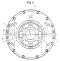
- Figures 2 and 6 illustrate a second preferred embodiment where like features have been given the same reference numbers as in Figures 1 and 3 to 5.
- two pairs of friction pads are provided with the pairs being arranged on diametrically opposed sides of the assembly.
- the embodiment allows only one pair of friction pads to be operably employed if satisfactory braking characteristics can be obtained thereby.
- the hub and disc 3 is made in two parts, a first inner section or hub 60 being adapted to be bolted or otherwise secured to an axle end and a second outer section (the disc) 61 is connected to the inner section 60 by a spline connection 62.
- the outer section 61 of the rotor disc has opposed annular braking surfaces 40 adapted to be engaged by friction pads 10.
- the splined connection enables the outer section 61 of the rotor disc (which is the part subject to wear) to be easily removed for repair or replacement.
- connection between the inner and outer parts could be used if desired, however, the splined connection 62 also has the advantage of enabling the outer section 61 to move axially so that only one positive operating mechanism 4 could be used for each pair of pads 10. It is, however, preferred that two such operating mechanismus 4 be employed, each of which includes a pair of piston members 14.
- the assembly also includes a pair of housing parts 1,2 defining a zone 44 in which the outer rotor section 61 rotates.
- the zone 44 is sealed by rotary seals 63,64 acting between the rotating inner section 60 of the rotor and the stationary housing parts 1,2.
- the piston members 14 of each operating mechanism are located in one of the housing parts 1 or 2.
- hydraulically operated brake assemblies e.g. dry friction brakes
- some form of positive return mechanism is required to move the piston members a significant distance away from the rotor disc when braking is not required. This is achieved via appropriate return springs, hydraulic means or by arranging angled annular seal rings in the wall of the piston cylinder which have the desired return effect when braking effect hydraulic pressure is released from the pistons.
- piston sealing rings 65 may be provided in the piston members 14 rather than the cylinder walls and via this arrangement, sufficient movement is achieved away from the rotor disc 3 when hydraulic pressure is removed from the spaces 66,67 as a result of braking effect no longer being required.
- Appropriate hydraulic fluid connections would of course be provided to the spaces 66,67 to allow brake activating pressure fluid to be delivered thereto or to be removed therefrom when braking effect is not required.
- Figures 7 to 10 illustrate several preferred forms of pad construction comprised of a desired friction material.
- the dotted outline represents the rotor 3 and the arrow 45 represents the direction of rotation of the rotor 3 past the pad 10.
- the pad has a leading edge 46, a trailing edge 47, an inner circumferential edge 48 and an outer circumferential edge 49.
- the leading edge 46 is swept in a continuous curve or straight line rearwardly at an acute angle x to a radial line 50 passing through the inner leading corner 51 of the pad.
- the front edge of the friction material 57 as opposed to the backing plate 70 may be angled as aforesaid rearwardly.
- the forward angled edge 71 of the friction material extend from the forward inner corner 51 as illustrated. Further, the rear inner corner of the friction material may be removed as illustrated along an angled line 72. Preferably the forward edge 46 of the backing plate 70 is notched at 73 to receive the pad anchor 74 thereby preventing incorrect installation of the pad. If desired, in this arrangement, the grooves could also be curved as in Figures 7 and 10.
- the various arrangements disclosed angling rearwardly the front edge of the friction material has the effect of acting to direct oil film from the rotor surface outwardly away from the pad to minimise its effect on frictional characteristics. If desired a wiper element might be added in front of this leading edge to further limit the effect of this oil film on frictional characteristics.
- This effect may be improved by ensuring the operating mechanism 4 applies a greater pressure to the leading edge 46 relative to the trailing edge 47.
- the dotted outlines 68,69 schematically represent the positioning of the operating pistons 14. As shown, the location 68 of the forward piston 14 is partially over the leading edge 46 to relatively increase the pressure thereon. In addition, this effect might be improved by angling the leading edge rearwardly by an angle between 0 and 30' from the perpendicular to the rotor disc braking surfaces 40.
- a series of grooves 52, 53 may be provided, preferably as illustrated extending from the pad edge 48 to either of the pad edges 49 or 47. Again the intention is to direct liquid oil through the grooves outwardly and away from the friction surface 55 of the pad.
- the grooves may be straight as shown at 52, or curved as shown at 53, and each preferably forms an acute angle with radial lines 56 at the inner edge 48. These acute angles are preferably equal to or greater than the angle x and preferably increase in a direction from the leading edge 46 to the rear edge 47. As shown in Figures 9 and 10, it is preferred that the number of grooves per unit area in a forward zone of the pad be greater than that in a rearward zone of the pad. Again this is believed to improve the removal of liquid oil from the braking surfaces.
- the cross-sectional shape of the grooves 52,53 may be square edged, however, it is preferred that the trailing edge of each groove be perpendicular to the braking surface or be angled rearwardly as illustrated in Figure 11A.
- the angle to the perpendicular may be from 0 to 30°, preferably, about 15°.
- the depth of the grooves should be sufficiently deep to exist operably over the complete working life of the pad.
- the rear edge of the or each groove should be a substantially sharp edge, i.e. not with a radius or bevel.
Abstract
Description
Claims (11)
- A disc brake assembly for a vehicle adapted to be connected to an axle end of the vehicle, said disc brake assembly including a single rotor disc (3) which in use rotates with said axle end, and a stationary housing (1,2) enclosing said rotor disc (3) with one or more seals (18,19,20) acting to provide a substantially sealed zone (44) surrounding at least a braking effect region (40) of said rotor disc (3), oil filling means (23) provided to permit at least part of said substantially sealed zone (44) to be filled with oil whereby in use said braking effect region (40) of said rotor disc (3) passes through said oil, said disc brake assembly further including at least one friction pad (10) located adjacent the braking effect region (40) of said rotor disc (3) with at least one said friction pad (10) being arranged to move axially towards and to engage said braking effect region (40) of the rotor disc (3) to apply brake effect thereto, said at least one friction pad (10) having a leading edge (46,71), a trailing edge (47), a radially inner edge (48), and a radially outer edge (49) defining a friction surface (55) therebetween, said disc brake assembly being characterised by at least one groove (52,53) extending inwardly from said friction surface, the or each said groove (52,53) extending between either said leading edge (46,71) or said radially inner edge (48) and either said radially outer edge (49) or said trailing edge (47) the or each said groove (52,53) in use, extending rearwardly and outwardly from a radial line at an acute angle at each point along the length of the groove.
- A disc brake assembly according to Claim 1, characterised in that a trailing edge of the or each said groove (52,53) forms an angle to said friction surface (55) between 60° and 90°.
- A disc brake assembly according to Claim 1 or Claim 2, characterised in that each said groove (52,53) is curved in a continuous rearwardly angled arc.
- A disc brake assembly according to any one of Claims 1 to 3, characterised in that spacing between said grooves (52,53) in a first zone adjacent the leading edge (46,71) of the brake pad is less than spacing between the grooves in a second zone adjacent the trailing edge (47) of the pad configuration.
- A disc brake assembly according to any one of Claims 1 to 4, characterised in that said leading edge (46,71) is swept or angled rearwardly from a radial line passing through an inner leading corner region (51) of the brake pad (10).
- A disc brake assembly according to any one of Claims 1 to 5, characterised in that each said groove (52,53) is about 2mm wide and about 5mm deep.
- A disc brake assembly according to any one of Claims 1 to 6, characterised in that the grooves (52,53) have a depth sufficient to ensure the grooves (52,53) remain operationally effective over a safe working life of the brake pad (10).
- A disc brake assembly according to Claim 1, characterised in that at least one pair of said brake friction pads (10) is provided with at least one said brake friction pad (10) of a said pair being positively moveable towards said rotor disc (3) during a braking operation.
- A disc brake assembly according to Claim 8, characterised in that at least two pair of said brake friction pads (10) are provided.
- A disc brake assembly according to Claim 8 or Claim 9, characterised in that at least one said friction pad (10) of a said pair is positively moveable towards said rotor disc (3) by at least two actuators (14) one of said actuators (14) being arranged to provide an actuating force in a direction towards said rotor disc (3) directly to a leading edge (46,71) of said at least one friction pad (10).
- A disc brake assembly according to any one of Claims 8 to 10, wherein at least one pair of said brake friction pads (10) is located substantially no lower than a horizontal line through an axis of rotation of the rotor disc (3).
Applications Claiming Priority (7)
| Application Number | Priority Date | Filing Date | Title |
|---|---|---|---|
| AU8867/91 | 1991-10-11 | ||
| AUPK886791 | 1991-10-11 | ||
| AUPK8867/91 | 1991-10-11 | ||
| AU3155/92 | 1992-06-25 | ||
| AUPL3155/92 | 1992-06-25 | ||
| AUPL315592 | 1992-06-25 | ||
| PCT/AU1992/000540 WO1993007402A1 (en) | 1991-10-11 | 1992-10-09 | Wet disc brake |
Publications (3)
| Publication Number | Publication Date |
|---|---|
| EP0607248A1 EP0607248A1 (en) | 1994-07-27 |
| EP0607248A4 EP0607248A4 (en) | 1994-11-09 |
| EP0607248B1 true EP0607248B1 (en) | 1999-01-07 |
Family
ID=25644123
Family Applications (1)
| Application Number | Title | Priority Date | Filing Date |
|---|---|---|---|
| EP92921218A Expired - Lifetime EP0607248B1 (en) | 1991-10-11 | 1992-10-09 | Wet disc brake |
Country Status (17)
| Country | Link |
|---|---|
| US (1) | US5564533A (en) |
| EP (1) | EP0607248B1 (en) |
| JP (1) | JP3198314B2 (en) |
| KR (1) | KR100305109B1 (en) |
| AT (1) | ATE175477T1 (en) |
| AU (1) | AU659227B2 (en) |
| BR (1) | BR9206618A (en) |
| CA (1) | CA2121037C (en) |
| DE (1) | DE69228125T2 (en) |
| DK (1) | DK0607248T3 (en) |
| ES (1) | ES2129045T3 (en) |
| GR (1) | GR3029527T3 (en) |
| HK (1) | HK1014382A1 (en) |
| MY (1) | MY108057A (en) |
| NZ (1) | NZ244701A (en) |
| OA (1) | OA09934A (en) |
| WO (1) | WO1993007402A1 (en) |
Families Citing this family (26)
| Publication number | Priority date | Publication date | Assignee | Title |
|---|---|---|---|---|
| AU738677B2 (en) * | 1994-08-26 | 2001-09-20 | Safe Effect Pty Ltd | Wet disc brake |
| US6186285B1 (en) * | 1994-08-26 | 2001-02-13 | Brake Technologies Pty., Ltd. | Wet disc brake |
| ATE218681T1 (en) * | 1994-08-26 | 2002-06-15 | Brake Technologies Pty Ltd | WET DISC BRAKE |
| AUPM772094A0 (en) * | 1994-08-26 | 1994-09-22 | Parsons, Francis Edward | Wet disc brake |
| GB2304837A (en) * | 1995-09-07 | 1997-03-26 | Automotive Products Plc | A disc brake caliper arrangement |
| FR2738887B1 (en) * | 1995-09-15 | 1997-12-05 | Peugeot | DISC BRAKE PAD FOR MOTOR VEHICLE WHEEL |
| US5690347A (en) * | 1996-04-15 | 1997-11-25 | Tractor Trailer Safety Systems, Inc. | Tractor trailer integrated jackknife control device |
| ES1042797Y (en) * | 1999-04-16 | 2000-03-16 | Aloy Jordi Nadal | PERFECTED DISC BRAKE. |
| NZ524440A (en) | 2000-08-01 | 2005-01-28 | Safe Effect Technologies Inter | Brake plate |
| KR20030038683A (en) * | 2000-08-01 | 2003-05-16 | 세이프 이펙트 테크놀로지즈 인터내셔널 리미티드 | Wet brake system |
| AUPR018700A0 (en) * | 2000-09-18 | 2000-10-12 | Safe Effect Technologies International Limited | A brake shoe and drum brake system incorporating same |
| JP4193575B2 (en) * | 2003-05-14 | 2008-12-10 | 株式会社アドヴィックス | Disc brake device |
| US20080047786A1 (en) * | 2003-06-06 | 2008-02-28 | Safe Effect Pty Ltd | Fluid cooled wet brake system |
| US8505698B2 (en) * | 2007-08-01 | 2013-08-13 | Federal-Mogul Products, Inc. | Brake pad |
| US8151433B2 (en) | 2007-08-01 | 2012-04-10 | Federal-Mogul Products, Inc. | Method of making disc brake pads |
| AU2010100626A4 (en) | 2009-12-08 | 2010-08-19 | Advanced Braking Pty Ltd | Disc Brake System |
| EP2383485B1 (en) * | 2010-04-30 | 2013-02-13 | Brembo SGL Carbon Ceramic Brakes GmbH | Brake pads for wet braking performance |
| WO2014176629A1 (en) * | 2013-04-29 | 2014-11-06 | Advanced Braking Pty Ltd | Disc brake system |
| JP5751288B2 (en) * | 2013-06-27 | 2015-07-22 | トヨタ自動車株式会社 | Disc brake device and a pair of brake pads |
| WO2015003703A1 (en) * | 2013-07-09 | 2015-01-15 | Schaeffler Technologies Gmbh & Co. Kg | Friction surface |
| CN106536964B (en) | 2014-06-13 | 2019-03-01 | 辉门汽车零部件公司 | Disc brake pads for vehicle |
| DE102015108049A1 (en) * | 2015-05-21 | 2016-11-24 | Tmd Friction Services Gmbh | Brake lining in disc brakes, especially of vehicles, with groove formation in the friction lining |
| US10962072B2 (en) * | 2015-12-17 | 2021-03-30 | Federal-Mogul Motorparts Llc | Friction lining and brake pad for a braking system |
| WO2019005659A1 (en) | 2017-06-28 | 2019-01-03 | Federal-Mogul Motorparts Llc | Disc brake pad for a vehicle |
| CN112224181A (en) * | 2020-08-31 | 2021-01-15 | 南京视莱尔汽车电子有限公司 | Emergency cooling system and method for automobile brake disc |
| DE102020125033A1 (en) | 2020-09-25 | 2022-03-31 | Mann+Hummel Gmbh | Brake pad for a disc brake assembly |
Family Cites Families (15)
| Publication number | Priority date | Publication date | Assignee | Title |
|---|---|---|---|---|
| US1890425A (en) * | 1931-09-23 | 1932-12-06 | Colt S Mfg Co | Brake lining and method of making |
| US2163884A (en) * | 1936-07-06 | 1939-06-27 | Bendix Prod Corp | Brake |
| FR1014836A (en) * | 1949-03-22 | 1952-08-22 | Dunlop Rubber Co | Disc brake improvements |
| US2799367A (en) * | 1954-04-30 | 1957-07-16 | Meadville Res Products Corp | Magazine brakes |
| GB1124004A (en) * | 1965-02-13 | 1968-08-14 | Mario Barale | Braking device for vehicle wheels |
| US4030185A (en) * | 1974-05-14 | 1977-06-21 | Itt Industries, Incorporated | Method of manufacturing a brake pad assembly for a spot-type disc brake |
| DE2539557A1 (en) * | 1975-09-05 | 1977-03-10 | Messerschmitt Boelkow Blohm | Friction brake with shoes protected from water - has inserted angled edging strip at angle to direction of friction force |
| JPS5794139A (en) * | 1980-12-03 | 1982-06-11 | Sumitomo Electric Ind Ltd | Multi-pot type disc brake |
| DE3109939A1 (en) * | 1981-03-14 | 1982-09-30 | Kurt 5000 Köln Stahl | FRICTION JACK FOR A DISC BRAKE |
| GB2115507B (en) * | 1982-02-25 | 1985-10-16 | Bba Group Ltd | Disc-brake assembly |
| DE3564730D1 (en) * | 1984-06-29 | 1988-10-06 | Allied Corp | Disc brake pad |
| AT384793B (en) * | 1985-11-06 | 1988-01-11 | Steyr Daimler Puch Ag | RIM OR DISC BRAKE FOR VEHICLES |
| JPS63190938A (en) * | 1987-01-31 | 1988-08-08 | Mazda Motor Corp | Brake device for vehicle |
| DE4036908A1 (en) * | 1990-11-20 | 1992-05-21 | Ruetgers Pagid Ag | GROOVE TRAINING |
| US6678274B1 (en) * | 1999-07-30 | 2004-01-13 | Riverstone Networks, Inc. | Method and system for managing forwarding tables |
-
1992
- 1992-10-09 DE DE69228125T patent/DE69228125T2/en not_active Expired - Fee Related
- 1992-10-09 JP JP50648093A patent/JP3198314B2/en not_active Expired - Fee Related
- 1992-10-09 WO PCT/AU1992/000540 patent/WO1993007402A1/en active IP Right Grant
- 1992-10-09 BR BR9206618A patent/BR9206618A/en not_active IP Right Cessation
- 1992-10-09 ES ES92921218T patent/ES2129045T3/en not_active Expired - Lifetime
- 1992-10-09 EP EP92921218A patent/EP0607248B1/en not_active Expired - Lifetime
- 1992-10-09 DK DK92921218T patent/DK0607248T3/en active
- 1992-10-09 US US08/211,577 patent/US5564533A/en not_active Expired - Lifetime
- 1992-10-09 AT AT92921218T patent/ATE175477T1/en not_active IP Right Cessation
- 1992-10-09 KR KR1019940701142A patent/KR100305109B1/en not_active IP Right Cessation
- 1992-10-09 AU AU27511/92A patent/AU659227B2/en not_active Ceased
- 1992-10-09 CA CA002121037A patent/CA2121037C/en not_active Expired - Fee Related
- 1992-10-10 MY MYPI92001832A patent/MY108057A/en unknown
- 1992-10-12 NZ NZ244701A patent/NZ244701A/en unknown
-
1994
- 1994-04-08 OA OA60494A patent/OA09934A/en unknown
-
1998
- 1998-12-24 HK HK98115713A patent/HK1014382A1/en not_active IP Right Cessation
-
1999
- 1999-03-01 GR GR990400622T patent/GR3029527T3/en unknown
Also Published As
| Publication number | Publication date |
|---|---|
| EP0607248A4 (en) | 1994-11-09 |
| AU2751192A (en) | 1993-05-03 |
| HK1014382A1 (en) | 1999-09-24 |
| EP0607248A1 (en) | 1994-07-27 |
| AU659227B2 (en) | 1995-05-11 |
| JPH06511539A (en) | 1994-12-22 |
| BR9206618A (en) | 1995-03-14 |
| US5564533A (en) | 1996-10-15 |
| OA09934A (en) | 1994-11-15 |
| ATE175477T1 (en) | 1999-01-15 |
| WO1993007402A1 (en) | 1993-04-15 |
| JP3198314B2 (en) | 2001-08-13 |
| DE69228125D1 (en) | 1999-02-18 |
| NZ244701A (en) | 1995-05-26 |
| DE69228125T2 (en) | 1999-08-26 |
| KR100305109B1 (en) | 2002-04-24 |
| MY108057A (en) | 1996-07-30 |
| CA2121037C (en) | 2003-06-17 |
| CA2121037A1 (en) | 1993-04-15 |
| GR3029527T3 (en) | 1999-06-30 |
| ES2129045T3 (en) | 1999-06-01 |
| DK0607248T3 (en) | 1999-08-30 |
Similar Documents
| Publication | Publication Date | Title |
|---|---|---|
| EP0607248B1 (en) | Wet disc brake | |
| US3198295A (en) | Friction couple cooling device | |
| CA1197479A (en) | Braking apparatus | |
| US3048250A (en) | Friction disc for brakes, clutches and the like | |
| US5012901A (en) | Self-energizing disc brakes | |
| EP0136434B1 (en) | Disc brake | |
| US20060231356A1 (en) | Brake Shoe and Drum Brake System Incorporating Same | |
| GB2184801A (en) | Disc brakes | |
| AU2001293474A1 (en) | A brake shoe and drum brake system incorporating same | |
| US2799367A (en) | Magazine brakes | |
| EP0916036A1 (en) | Park and service brake arrangements | |
| US3303911A (en) | Fluid cooled brake mechanism | |
| US3580369A (en) | Liquid-cooled disc brake assembly | |
| US4646885A (en) | Dual drum brake assembly | |
| WO2005021993A1 (en) | Fluid cooled drum brake system | |
| GB2163500A (en) | Disk brake | |
| CA1059042A (en) | Disc brake | |
| CN212243315U (en) | Driven axle braking system | |
| US4650041A (en) | Dual drum brake assembly with cooling means | |
| CN111409606A (en) | Driven axle braking system | |
| EP1081403A2 (en) | Sealed dry disc brake | |
| JP2532876B2 (en) | Fluid type retarder with parking brake | |
| KR200281973Y1 (en) | Drum brake | |
| AU729571B2 (en) | Park and service brake arrangements | |
| WO2014176629A1 (en) | Disc brake system |
Legal Events
| Date | Code | Title | Description |
|---|---|---|---|
| PUAI | Public reference made under article 153(3) epc to a published international application that has entered the european phase |
Free format text: ORIGINAL CODE: 0009012 |
|
| 17P | Request for examination filed |
Effective date: 19940509 |
|
| AK | Designated contracting states |
Kind code of ref document: A1 Designated state(s): AT BE CH DE DK ES FR GB GR IE IT LI LU MC NL SE |
|
| A4 | Supplementary search report drawn up and despatched | ||
| AK | Designated contracting states |
Kind code of ref document: A4 Designated state(s): AT BE CH DE DK ES FR GB GR IE IT LI LU MC NL SE |
|
| 17Q | First examination report despatched |
Effective date: 19960308 |
|
| GRAG | Despatch of communication of intention to grant |
Free format text: ORIGINAL CODE: EPIDOS AGRA |
|
| GRAG | Despatch of communication of intention to grant |
Free format text: ORIGINAL CODE: EPIDOS AGRA |
|
| GRAH | Despatch of communication of intention to grant a patent |
Free format text: ORIGINAL CODE: EPIDOS IGRA |
|
| GRAH | Despatch of communication of intention to grant a patent |
Free format text: ORIGINAL CODE: EPIDOS IGRA |
|
| GRAA | (expected) grant |
Free format text: ORIGINAL CODE: 0009210 |
|
| AK | Designated contracting states |
Kind code of ref document: B1 Designated state(s): AT BE CH DE DK ES FR GB GR IE IT LI LU MC NL SE |
|
| REF | Corresponds to: |
Ref document number: 175477 Country of ref document: AT Date of ref document: 19990115 Kind code of ref document: T |
|
| REG | Reference to a national code |
Ref country code: CH Ref legal event code: EP |
|
| REF | Corresponds to: |
Ref document number: 69228125 Country of ref document: DE Date of ref document: 19990218 |
|
| REG | Reference to a national code |
Ref country code: IE Ref legal event code: FG4D |
|
| ET | Fr: translation filed | ||
| ITF | It: translation for a ep patent filed |
Owner name: STUDIO TORTA S.R.L. |
|
| REG | Reference to a national code |
Ref country code: CH Ref legal event code: NV Representative=s name: HUG INTERLIZENZ AG |
|
| REG | Reference to a national code |
Ref country code: ES Ref legal event code: FG2A Ref document number: 2129045 Country of ref document: ES Kind code of ref document: T3 |
|
| REG | Reference to a national code |
Ref country code: DK Ref legal event code: T3 |
|
| RAP2 | Party data changed (patent owner data changed or rights of a patent transferred) |
Owner name: BRAKE TECHNOLOGIES PTY. LTD. |
|
| RIN2 | Information on inventor provided after grant (corrected) |
Free format text: BRAKE TECHNOLOGIES PTY. LTD. |
|
| PLBE | No opposition filed within time limit |
Free format text: ORIGINAL CODE: 0009261 |
|
| STAA | Information on the status of an ep patent application or granted ep patent |
Free format text: STATUS: NO OPPOSITION FILED WITHIN TIME LIMIT |
|
| 26N | No opposition filed | ||
| REG | Reference to a national code |
Ref country code: GB Ref legal event code: IF02 |
|
| PGFP | Annual fee paid to national office [announced via postgrant information from national office to epo] |
Ref country code: IE Payment date: 20040421 Year of fee payment: 12 Ref country code: DK Payment date: 20040421 Year of fee payment: 12 Ref country code: BE Payment date: 20040421 Year of fee payment: 12 |
|
| PGFP | Annual fee paid to national office [announced via postgrant information from national office to epo] |
Ref country code: SE Payment date: 20040422 Year of fee payment: 12 |
|
| PGFP | Annual fee paid to national office [announced via postgrant information from national office to epo] |
Ref country code: CH Payment date: 20040423 Year of fee payment: 12 |
|
| PGFP | Annual fee paid to national office [announced via postgrant information from national office to epo] |
Ref country code: LU Payment date: 20040426 Year of fee payment: 12 Ref country code: AT Payment date: 20040426 Year of fee payment: 12 |
|
| PGFP | Annual fee paid to national office [announced via postgrant information from national office to epo] |
Ref country code: NL Payment date: 20040427 Year of fee payment: 12 |
|
| PGFP | Annual fee paid to national office [announced via postgrant information from national office to epo] |
Ref country code: MC Payment date: 20040428 Year of fee payment: 12 |
|
| PGFP | Annual fee paid to national office [announced via postgrant information from national office to epo] |
Ref country code: GR Payment date: 20040430 Year of fee payment: 12 |
|
| PG25 | Lapsed in a contracting state [announced via postgrant information from national office to epo] |
Ref country code: LU Free format text: LAPSE BECAUSE OF NON-PAYMENT OF DUE FEES Effective date: 20041009 Ref country code: AT Free format text: LAPSE BECAUSE OF NON-PAYMENT OF DUE FEES Effective date: 20041009 |
|
| PG25 | Lapsed in a contracting state [announced via postgrant information from national office to epo] |
Ref country code: SE Free format text: LAPSE BECAUSE OF NON-PAYMENT OF DUE FEES Effective date: 20041010 |
|
| PG25 | Lapsed in a contracting state [announced via postgrant information from national office to epo] |
Ref country code: IE Free format text: LAPSE BECAUSE OF NON-PAYMENT OF DUE FEES Effective date: 20041011 |
|
| PG25 | Lapsed in a contracting state [announced via postgrant information from national office to epo] |
Ref country code: MC Free format text: LAPSE BECAUSE OF NON-PAYMENT OF DUE FEES Effective date: 20041031 Ref country code: LI Free format text: LAPSE BECAUSE OF NON-PAYMENT OF DUE FEES Effective date: 20041031 Ref country code: CH Free format text: LAPSE BECAUSE OF NON-PAYMENT OF DUE FEES Effective date: 20041031 Ref country code: BE Free format text: LAPSE BECAUSE OF NON-PAYMENT OF DUE FEES Effective date: 20041031 |
|
| PG25 | Lapsed in a contracting state [announced via postgrant information from national office to epo] |
Ref country code: DK Free format text: LAPSE BECAUSE OF NON-PAYMENT OF DUE FEES Effective date: 20041101 |
|
| PGFP | Annual fee paid to national office [announced via postgrant information from national office to epo] |
Ref country code: ES Payment date: 20050429 Year of fee payment: 13 |
|
| BERE | Be: lapsed |
Owner name: *PARSONS FRANCIS EDWARD Effective date: 20041031 |
|
| PG25 | Lapsed in a contracting state [announced via postgrant information from national office to epo] |
Ref country code: NL Free format text: LAPSE BECAUSE OF NON-PAYMENT OF DUE FEES Effective date: 20050501 |
|
| PG25 | Lapsed in a contracting state [announced via postgrant information from national office to epo] |
Ref country code: GR Free format text: LAPSE BECAUSE OF NON-PAYMENT OF DUE FEES Effective date: 20050504 |
|
| EUG | Se: european patent has lapsed | ||
| REG | Reference to a national code |
Ref country code: DK Ref legal event code: EBP |
|
| REG | Reference to a national code |
Ref country code: CH Ref legal event code: PL |
|
| NLV4 | Nl: lapsed or anulled due to non-payment of the annual fee |
Effective date: 20050501 |
|
| REG | Reference to a national code |
Ref country code: IE Ref legal event code: MM4A |
|
| PG25 | Lapsed in a contracting state [announced via postgrant information from national office to epo] |
Ref country code: ES Free format text: LAPSE BECAUSE OF NON-PAYMENT OF DUE FEES Effective date: 20051010 |
|
| PGFP | Annual fee paid to national office [announced via postgrant information from national office to epo] |
Ref country code: IT Payment date: 20061031 Year of fee payment: 15 |
|
| REG | Reference to a national code |
Ref country code: ES Ref legal event code: FD2A Effective date: 20051010 |
|
| BERE | Be: lapsed |
Owner name: *PARSONS FRANCIS EDWARD Effective date: 20041031 |
|
| REG | Reference to a national code |
Ref country code: FR Ref legal event code: ST Effective date: 20080630 |
|
| PGFP | Annual fee paid to national office [announced via postgrant information from national office to epo] |
Ref country code: FR Payment date: 20061010 Year of fee payment: 15 |
|
| PGFP | Annual fee paid to national office [announced via postgrant information from national office to epo] |
Ref country code: DE Payment date: 20081016 Year of fee payment: 17 |
|
| PG25 | Lapsed in a contracting state [announced via postgrant information from national office to epo] |
Ref country code: FR Free format text: LAPSE BECAUSE OF NON-PAYMENT OF DUE FEES Effective date: 20071031 |
|
| PGFP | Annual fee paid to national office [announced via postgrant information from national office to epo] |
Ref country code: GB Payment date: 20081126 Year of fee payment: 17 |
|
| PG25 | Lapsed in a contracting state [announced via postgrant information from national office to epo] |
Ref country code: IT Free format text: LAPSE BECAUSE OF NON-PAYMENT OF DUE FEES Effective date: 20071009 |
|
| PG25 | Lapsed in a contracting state [announced via postgrant information from national office to epo] |
Ref country code: DE Free format text: LAPSE BECAUSE OF NON-PAYMENT OF DUE FEES Effective date: 20100501 |
|
| PG25 | Lapsed in a contracting state [announced via postgrant information from national office to epo] |
Ref country code: GB Free format text: LAPSE BECAUSE OF NON-PAYMENT OF DUE FEES Effective date: 20091009 |