EP0607573A1 - Barrier coating - Google Patents
Barrier coating Download PDFInfo
- Publication number
- EP0607573A1 EP0607573A1 EP93120171A EP93120171A EP0607573A1 EP 0607573 A1 EP0607573 A1 EP 0607573A1 EP 93120171 A EP93120171 A EP 93120171A EP 93120171 A EP93120171 A EP 93120171A EP 0607573 A1 EP0607573 A1 EP 0607573A1
- Authority
- EP
- European Patent Office
- Prior art keywords
- layer
- polymer
- barrier coating
- assembly
- parylene
- Prior art date
- Legal status (The legal status is an assumption and is not a legal conclusion. Google has not performed a legal analysis and makes no representation as to the accuracy of the status listed.)
- Granted
Links
Images

Classifications
-
- B—PERFORMING OPERATIONS; TRANSPORTING
- B01—PHYSICAL OR CHEMICAL PROCESSES OR APPARATUS IN GENERAL
- B01L—CHEMICAL OR PHYSICAL LABORATORY APPARATUS FOR GENERAL USE
- B01L3/00—Containers or dishes for laboratory use, e.g. laboratory glassware; Droppers
- B01L3/50—Containers for the purpose of retaining a material to be analysed, e.g. test tubes
- B01L3/508—Containers for the purpose of retaining a material to be analysed, e.g. test tubes rigid containers not provided for above
- B01L3/5082—Test tubes per se
-
- A—HUMAN NECESSITIES
- A61—MEDICAL OR VETERINARY SCIENCE; HYGIENE
- A61B—DIAGNOSIS; SURGERY; IDENTIFICATION
- A61B5/00—Measuring for diagnostic purposes; Identification of persons
- A61B5/15—Devices for taking samples of blood
- A61B5/150007—Details
- A61B5/150015—Source of blood
- A61B5/15003—Source of blood for venous or arterial blood
-
- A—HUMAN NECESSITIES
- A61—MEDICAL OR VETERINARY SCIENCE; HYGIENE
- A61B—DIAGNOSIS; SURGERY; IDENTIFICATION
- A61B5/00—Measuring for diagnostic purposes; Identification of persons
- A61B5/15—Devices for taking samples of blood
- A61B5/150007—Details
- A61B5/150351—Caps, stoppers or lids for sealing or closing a blood collection vessel or container, e.g. a test-tube or syringe barrel
-
- A—HUMAN NECESSITIES
- A61—MEDICAL OR VETERINARY SCIENCE; HYGIENE
- A61B—DIAGNOSIS; SURGERY; IDENTIFICATION
- A61B5/00—Measuring for diagnostic purposes; Identification of persons
- A61B5/15—Devices for taking samples of blood
- A61B5/153—Devices specially adapted for taking samples of venous or arterial blood, e.g. with syringes
- A61B5/154—Devices using pre-evacuated means
-
- B—PERFORMING OPERATIONS; TRANSPORTING
- B65—CONVEYING; PACKING; STORING; HANDLING THIN OR FILAMENTARY MATERIAL
- B65D—CONTAINERS FOR STORAGE OR TRANSPORT OF ARTICLES OR MATERIALS, e.g. BAGS, BARRELS, BOTTLES, BOXES, CANS, CARTONS, CRATES, DRUMS, JARS, TANKS, HOPPERS, FORWARDING CONTAINERS; ACCESSORIES, CLOSURES, OR FITTINGS THEREFOR; PACKAGING ELEMENTS; PACKAGES
- B65D23/00—Details of bottles or jars not otherwise provided for
- B65D23/08—Coverings or external coatings
- B65D23/0807—Coatings
- B65D23/0814—Coatings characterised by the composition of the material
- B65D23/0821—Coatings characterised by the composition of the material consisting mainly of polymeric materials
-
- C—CHEMISTRY; METALLURGY
- C08—ORGANIC MACROMOLECULAR COMPOUNDS; THEIR PREPARATION OR CHEMICAL WORKING-UP; COMPOSITIONS BASED THEREON
- C08J—WORKING-UP; GENERAL PROCESSES OF COMPOUNDING; AFTER-TREATMENT NOT COVERED BY SUBCLASSES C08B, C08C, C08F, C08G or C08H
- C08J7/00—Chemical treatment or coating of shaped articles made of macromolecular substances
- C08J7/04—Coating
- C08J7/042—Coating with two or more layers, where at least one layer of a composition contains a polymer binder
- C08J7/0423—Coating with two or more layers, where at least one layer of a composition contains a polymer binder with at least one layer of inorganic material and at least one layer of a composition containing a polymer binder
-
- C—CHEMISTRY; METALLURGY
- C08—ORGANIC MACROMOLECULAR COMPOUNDS; THEIR PREPARATION OR CHEMICAL WORKING-UP; COMPOSITIONS BASED THEREON
- C08J—WORKING-UP; GENERAL PROCESSES OF COMPOUNDING; AFTER-TREATMENT NOT COVERED BY SUBCLASSES C08B, C08C, C08F, C08G or C08H
- C08J7/00—Chemical treatment or coating of shaped articles made of macromolecular substances
- C08J7/04—Coating
- C08J7/046—Forming abrasion-resistant coatings; Forming surface-hardening coatings
-
- C—CHEMISTRY; METALLURGY
- C08—ORGANIC MACROMOLECULAR COMPOUNDS; THEIR PREPARATION OR CHEMICAL WORKING-UP; COMPOSITIONS BASED THEREON
- C08J—WORKING-UP; GENERAL PROCESSES OF COMPOUNDING; AFTER-TREATMENT NOT COVERED BY SUBCLASSES C08B, C08C, C08F, C08G or C08H
- C08J7/00—Chemical treatment or coating of shaped articles made of macromolecular substances
- C08J7/04—Coating
- C08J7/048—Forming gas barrier coatings
-
- C—CHEMISTRY; METALLURGY
- C08—ORGANIC MACROMOLECULAR COMPOUNDS; THEIR PREPARATION OR CHEMICAL WORKING-UP; COMPOSITIONS BASED THEREON
- C08J—WORKING-UP; GENERAL PROCESSES OF COMPOUNDING; AFTER-TREATMENT NOT COVERED BY SUBCLASSES C08B, C08C, C08F, C08G or C08H
- C08J2323/00—Characterised by the use of homopolymers or copolymers of unsaturated aliphatic hydrocarbons having only one carbon-to-carbon double bond; Derivatives of such polymers
- C08J2323/02—Characterised by the use of homopolymers or copolymers of unsaturated aliphatic hydrocarbons having only one carbon-to-carbon double bond; Derivatives of such polymers not modified by chemical after treatment
- C08J2323/10—Homopolymers or copolymers of propene
- C08J2323/12—Polypropene
-
- C—CHEMISTRY; METALLURGY
- C08—ORGANIC MACROMOLECULAR COMPOUNDS; THEIR PREPARATION OR CHEMICAL WORKING-UP; COMPOSITIONS BASED THEREON
- C08J—WORKING-UP; GENERAL PROCESSES OF COMPOUNDING; AFTER-TREATMENT NOT COVERED BY SUBCLASSES C08B, C08C, C08F, C08G or C08H
- C08J2483/00—Characterised by the use of macromolecular compounds obtained by reactions forming in the main chain of the macromolecule a linkage containing silicon with or without sulfur, nitrogen, oxygen, or carbon only; Derivatives of such polymers
- C08J2483/04—Polysiloxanes
-
- Y—GENERAL TAGGING OF NEW TECHNOLOGICAL DEVELOPMENTS; GENERAL TAGGING OF CROSS-SECTIONAL TECHNOLOGIES SPANNING OVER SEVERAL SECTIONS OF THE IPC; TECHNICAL SUBJECTS COVERED BY FORMER USPC CROSS-REFERENCE ART COLLECTIONS [XRACs] AND DIGESTS
- Y10—TECHNICAL SUBJECTS COVERED BY FORMER USPC
- Y10T—TECHNICAL SUBJECTS COVERED BY FORMER US CLASSIFICATION
- Y10T428/00—Stock material or miscellaneous articles
- Y10T428/13—Hollow or container type article [e.g., tube, vase, etc.]
- Y10T428/131—Glass, ceramic, or sintered, fused, fired, or calcined metal oxide or metal carbide containing [e.g., porcelain, brick, cement, etc.]
- Y10T428/1317—Multilayer [continuous layer]
-
- Y—GENERAL TAGGING OF NEW TECHNOLOGICAL DEVELOPMENTS; GENERAL TAGGING OF CROSS-SECTIONAL TECHNOLOGIES SPANNING OVER SEVERAL SECTIONS OF THE IPC; TECHNICAL SUBJECTS COVERED BY FORMER USPC CROSS-REFERENCE ART COLLECTIONS [XRACs] AND DIGESTS
- Y10—TECHNICAL SUBJECTS COVERED BY FORMER USPC
- Y10T—TECHNICAL SUBJECTS COVERED BY FORMER US CLASSIFICATION
- Y10T428/00—Stock material or miscellaneous articles
- Y10T428/13—Hollow or container type article [e.g., tube, vase, etc.]
- Y10T428/1352—Polymer or resin containing [i.e., natural or synthetic]
- Y10T428/1379—Contains vapor or gas barrier, polymer derived from vinyl chloride or vinylidene chloride, or polymer containing a vinyl alcohol unit
- Y10T428/1383—Vapor or gas barrier, polymer derived from vinyl chloride or vinylidene chloride, or polymer containing a vinyl alcohol unit is sandwiched between layers [continuous layer]
Definitions
- This invention relates to a barrier coating for providing an effective barrier against gas and water permeability for containers, especially plastic evacuated blood collection tubes.
- Such medical products that would derive a considerable benefit from improving their barrier properties include, but are not limited to, collection tubes and particularly those used for blood collection.
- Blood collection tubes require certain performance standards to be acceptable for use in medical applications. Such performance standards include the ability to maintain greater than about 90% original draw volume over a one year period, to be radiation sterilizable and to be noninterfering in tests and analysis.
- the present invention is a plastic composite container coated with a barrier coating comprising at least two barrier materials.
- the barrier coating comprises a first layer of an inorganic material and a second layer of a polymer material.
- the first layer of the barrier coating may preferably be an aluminum oxide based composition, such as AlO x wherein x is from 0.3 to about 0.9; a silicon oxide based composition; or a diamond based composition. Most preferably, the first layer is an aluminum oxide based composition.
- the second layer may preferably be vinylidene chloride-acrylonitrile-methyl methacrylate-methyl acrylate-acrylic acid copolymers, thermosetting epoxy coatings, parylene polymers, or polyesters.
- the barrier coating may be formed either on an interior surface portion, on an exterior surface portion, or both of the container.
- the second layer is a parylene polymer.
- Parylene is the generic name for members of a polymer series developed by Union Carbide Corporation.
- the base member of the series, called parylene N is poly-p-xylylene, a linear, crystalline material: Parylene C
- a second member of the parylene series is produced from the same monomer as parylene N and modified by the substitution of a chlorine atom for one of the aromatic hydrogens:
- Parylene D the third member of the parylene series is produced from the same monomer as parylene N and modified by the substitution of the chlorine atom for two of the aromatic hydrogens:
- the polymer layer is a vinylidene chloride-methyl methacrylate-methacrylate acrylic acid polymer. This polymer is available as DARAN® 8600-C (trademark of W.R. Grace and Co.) sold by GRACE, Organic Chemicals Division, Lexington, Mass.
- Plastic tubes coated with the barrier coating are able to maintain substantially far better vacuum retention and draw volume retention than previous tubes comprised of polymer compositions and blends thereof without a coating of barrier materials.
- Printing may be placed on the barrier coating applied to the container of interest.
- a product identification, bar code, brand name, company logo, lot number, expiration date and other data and information may all be included on the barrier coating.
- a matte finish or a corona discharged surface may be developed on the barrier coating so as to make the surface appropriate for writing additional information on the label.
- a pressure sensitive adhesive label may be placed over the barrier coating so as to accommodate various hospital over-labels, for example.
- FIG. 1 is a perspective view of a typical blood collection tube with a stopper.
- FIG. 2 is a longitudinal sectional view of the tube of FIG. 1 taken along line 2-2.
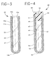
- FIG. 3 is a longitudinal sectional view of a tube-shaped container, similar to the tube of FIG. 1 without a stopper, comprising a barrier coating.
- FIG. 4 is a longitudinal sectional view of a tube-shaped container, similar to the tube of FIG. 1 with a stopper, comprising a barrier coating.
- FIGS. 1 and 2 show a typical blood collection tube 10 , having a sidewall 11 extending from an open end 16 to a closed end 18 and stopper 14 which includes a lower annular portion or skirt 15 which extends into and presses against the inner surface 12 of the sidewall for maintaining stopper 14 in place.
- FIG. 3 shows the preferred embodiment of the invention, a plastic tube coated with at least two layers of barrier materials.
- the preferred embodiment includes many components which are substantially identical to the components of FIGS. 1 and 2. Accordingly, similar components performing similar functions will be numbered identically to those components of FIGS. 1 and 2, except that a suffix "a" will be used to identify those components in FIG. 3.
- collection tube assembly 20 comprises a plastic tube 10a , having a sidewall 11a extending from an open end 16a to a closed end 18a .
- a barrier coating 25 extends over a substantial portion of the length of the tube which is upon the outer surface of the tube with the exception of open end 16a .
- Barrier coating 25 comprises a first layer 26 of an inorganic material and a second layer 27 of a polymer material.
- FIG. 4 illustrates an alternate embodiment of the invention, wherein collection tube assembly 40 comprises stopper 48 in place for closing open end 41 of tube 42 .
- sidewall 43 extends from open end 41 to closed end 44 and stopper 48 includes an annular upper portion 50 which extends over the top edge of tube 42 .
- Stopper 48 includes a lower annular portion or skirt 49 which extends into and presses against the inside inner surface 46 of sidewall 43 for maintaining stopper 48 in place and a well 52 .
- Barrier coating 45 covers substantially most of the tube with the exception of open end 41 thereof.
- Barrier coating 45 comprises a first layer 54 of an inorganic material and a second layer 56 of a polymer material.
- FIG. 4 differs from the embodiment in FIG. 3 in that the tube may be evacuated with the simultaneous placement of stopper 48 therein after the application of barrier coating 45 over the tube.
- the barrier coating may be applied to the tube before it has been evacuated.
- An alternate embodiment of the invention also includes a barrier coating incorporating both the upper portion of the stopper, as well as the entire container tube. Such an embodiment may be utilized, for example, for sealing the container with the stopper in place. Once a sample has been placed in the tube, the sample cannot be tampered with by removal of the stopper. Additionally, serrations could be included at the tube, stopper interface. The serrations may be registered so that it can be determined if the sealed container has been tampered with.
- tubes may also contain reagents in the form of additives or coatings on the inner wall of the tube.
- the barrier coating forms a substantially clear or translucent barrier. Therefore, the contents of a plastic tube layered with a barrier coating comprising at least two layers of barrier materials are substantially visible to the observer at the same time identifying information may be displayed over the barrier coating after it is applied to the plastic tube.
- the inorganic material of the barrier coating may be formed on a substrate as a first layer by radio frequency discharge, direct or dual ion beam deposition, sputtering or plasma chemical vapor deposition, as described in U.S. Patent Nos. 4,698,256, 4,809,876, 4,992,298 and 5,055,318, the disclosures of which are herein incorporated by reference.
- the second layer of the barrier coating may be a parylene polymer applied to the first layer by a process similar to vacuum metallizing, as described in U.S. Patent Nos. 3,342,754 and 3,300,332, the disclosures of which are herein incorporated by reference.
- the second layer may be vinylidene chloride-acrylonitrile-methyl methacrylate-methyl acrylate-acid acrylic polymer, applied to the first layer by dip-coating, roll-coating or spraying an aqueous emulsion of the polymer, followed by air drying of the coating, as described in U.S. Patent Nos. 5,093,194 and 4,497,859, the disclosure of which are herein incorporated by reference.
- the barrier coating of the present invention is preferably a first layer material comprising aluminum oxide, and a second layer of vinylidene chloride-acrylonitrile-methyl methacrylate-methyl acrylate-acrylic acid polymer applied to the first layer.
- a plastic blood collection tube coated with the barrier coating will not interfere with testing and analysis that is typically performed on blood in a tube. Such tests include but are not limited to, routine chemical analysis, biological inertness, hematology, blood chemistry, blood typing, toxicology analysis or therapeutic drug monitoring and other clinical tests involving body fluids. Furthermore, a plastic blood collection tube coated with the barrier coating is capable of being subjected to automated machinery such as centrifuges and may be exposed to certain levels of radiation in the sterilization process with substantially no change in optical or mechanical and functional properties.
- a plastic blood collection tube coated with the barrier coating is able to maintain 90% original draw volume over a period of one year.
- Draw volume retention depends on the existence of a partial vacuum, or reduced pressure, inside the tube. The draw volume changes in direct proportion to the change in vacuum (reduced pressure). Therefore, draw volume retention is dependent on good vacuum retention.
- a plastic tube coated with a barrier coating substantially prevents gas permeation through the tube material so as to maintain and enhance the vacuum retention and draw volume retention of the tube.
- the barrier coating may be hemorepellent and/or have characteristics of a clot activator if the first layer of the barrier coating is a diamond composition.
- plastic composite container is evacuated or not evacuated in accordance with this invention.
- the presence of a barrier coating on the outer surface of the container has the effect of maintaining the general integrity of the container holding a sample so that it may be properly disposed of without any contamination to the user. Notable is the clarity of the barrier coating as coated or applied on the container and its abrasion and scratch resistance.
- the barrier coating used in accordance with this disclosure may contain conventional additives and ingredients which do not adversely affect the properties of articles made therefrom.
Abstract
Description
- This invention relates to a barrier coating for providing an effective barrier against gas and water permeability for containers, especially plastic evacuated blood collection tubes.
- With the increased emphasis on the use of plastic medical products, a special need exists for improving the barrier properties of articles made of polymers.
- Such medical products that would derive a considerable benefit from improving their barrier properties include, but are not limited to, collection tubes and particularly those used for blood collection.
- Blood collection tubes require certain performance standards to be acceptable for use in medical applications. Such performance standards include the ability to maintain greater than about 90% original draw volume over a one year period, to be radiation sterilizable and to be noninterfering in tests and analysis.
- Therefore, a need exists to improve the barrier properties of articles made of polymers and in particular plastic evacuated blood collection tubes wherein certain performance standards would be able to be met and the article would be effective and usable in medical applications.
- The present invention is a plastic composite container coated with a barrier coating comprising at least two barrier materials. Desirably, the barrier coating comprises a first layer of an inorganic material and a second layer of a polymer material.
- The first layer of the barrier coating may preferably be an aluminum oxide based composition, such as AlOx wherein x is from 0.3 to about 0.9; a silicon oxide based composition; or a diamond based composition. Most preferably, the first layer is an aluminum oxide based composition.
- The second layer may preferably be vinylidene chloride-acrylonitrile-methyl methacrylate-methyl acrylate-acrylic acid copolymers, thermosetting epoxy coatings, parylene polymers, or polyesters. The barrier coating may be formed either on an interior surface portion, on an exterior surface portion, or both of the container.
- Preferably, the second layer is a parylene polymer. Parylene is the generic name for members of a polymer series developed by Union Carbide Corporation. The base member of the series, called parylene N, is poly-p-xylylene, a linear, crystalline material:

Parylene C, a second member of the parylene series is produced from the same monomer as parylene N and modified by the substitution of a chlorine atom for one of the aromatic hydrogens:
Parylene D, the third member of the parylene series is produced from the same monomer as parylene N and modified by the substitution of the chlorine atom for two of the aromatic hydrogens:
Most preferably, the polymer layer is a vinylidene chloride-methyl methacrylate-methacrylate acrylic acid polymer. This polymer is available as DARAN® 8600-C (trademark of W.R. Grace and Co.) sold by GRACE, Organic Chemicals Division, Lexington, Mass. - Plastic tubes coated with the barrier coating are able to maintain substantially far better vacuum retention and draw volume retention than previous tubes comprised of polymer compositions and blends thereof without a coating of barrier materials.
- Printing may be placed on the barrier coating applied to the container of interest. For example, a product identification, bar code, brand name, company logo, lot number, expiration date and other data and information may all be included on the barrier coating. Moreover, a matte finish or a corona discharged surface may be developed on the barrier coating so as to make the surface appropriate for writing additional information on the label. Furthermore, a pressure sensitive adhesive label may be placed over the barrier coating so as to accommodate various hospital over-labels, for example.
- FIG. 1 is a perspective view of a typical blood collection tube with a stopper.
- FIG. 2 is a longitudinal sectional view of the tube of FIG. 1 taken along line 2-2.
- FIG. 3 is a longitudinal sectional view of a tube-shaped container, similar to the tube of FIG. 1 without a stopper, comprising a barrier coating.
- FIG. 4 is a longitudinal sectional view of a tube-shaped container, similar to the tube of FIG. 1 with a stopper, comprising a barrier coating.
- Referring to the drawings in which like reference characters refer to like parts throughout the several views thereof, FIGS. 1 and 2 show a typical
blood collection tube 10, having asidewall 11 extending from anopen end 16 to a closedend 18 andstopper 14 which includes a lower annular portion orskirt 15 which extends into and presses against theinner surface 12 of the sidewall for maintainingstopper 14 in place. - FIG. 3 shows the preferred embodiment of the invention, a plastic tube coated with at least two layers of barrier materials. The preferred embodiment includes many components which are substantially identical to the components of FIGS. 1 and 2. Accordingly, similar components performing similar functions will be numbered identically to those components of FIGS. 1 and 2, except that a suffix "a" will be used to identify those components in FIG. 3.
- Referring now to FIG. 3, the preferred embodiment of the invention,
collection tube assembly 20 comprises aplastic tube 10a, having asidewall 11a extending from anopen end 16a to a closedend 18a. Abarrier coating 25 extends over a substantial portion of the length of the tube which is upon the outer surface of the tube with the exception ofopen end 16a.Barrier coating 25 comprises afirst layer 26 of an inorganic material and asecond layer 27 of a polymer material. - FIG. 4 illustrates an alternate embodiment of the invention, wherein
collection tube assembly 40 comprisesstopper 48 in place for closingopen end 41 oftube 42. As can be seen,sidewall 43 extends fromopen end 41 to closedend 44 andstopper 48 includes an annularupper portion 50 which extends over the top edge oftube 42.Stopper 48 includes a lower annular portion orskirt 49 which extends into and presses against the insideinner surface 46 ofsidewall 43 for maintainingstopper 48 in place and awell 52. - Covering a substantial portion of the length of the tube is a barrier coating 45.
Barrier coating 45 covers substantially most of the tube with the exception ofopen end 41 thereof.Barrier coating 45 comprises afirst layer 54 of an inorganic material and asecond layer 56 of a polymer material. - FIG. 4 differs from the embodiment in FIG. 3 in that the tube may be evacuated with the simultaneous placement of
stopper 48 therein after the application of barrier coating 45 over the tube. Alternatively, the barrier coating may be applied to the tube before it has been evacuated. - An alternate embodiment of the invention also includes a barrier coating incorporating both the upper portion of the stopper, as well as the entire container tube. Such an embodiment may be utilized, for example, for sealing the container with the stopper in place. Once a sample has been placed in the tube, the sample cannot be tampered with by removal of the stopper. Additionally, serrations could be included at the tube, stopper interface. The serrations may be registered so that it can be determined if the sealed container has been tampered with.
- It will be understood by practitioners-in-the-art that such tubes may also contain reagents in the form of additives or coatings on the inner wall of the tube.
- The barrier coating forms a substantially clear or translucent barrier. Therefore, the contents of a plastic tube layered with a barrier coating comprising at least two layers of barrier materials are substantially visible to the observer at the same time identifying information may be displayed over the barrier coating after it is applied to the plastic tube.
- The inorganic material of the barrier coating may be formed on a substrate as a first layer by radio frequency discharge, direct or dual ion beam deposition, sputtering or plasma chemical vapor deposition, as described in U.S. Patent Nos. 4,698,256, 4,809,876, 4,992,298 and 5,055,318, the disclosures of which are herein incorporated by reference.
- The second layer of the barrier coating, a polymer material, may be a parylene polymer applied to the first layer by a process similar to vacuum metallizing, as described in U.S. Patent Nos. 3,342,754 and 3,300,332, the disclosures of which are herein incorporated by reference. Alternatively, the second layer may be vinylidene chloride-acrylonitrile-methyl methacrylate-methyl acrylate-acid acrylic polymer, applied to the first layer by dip-coating, roll-coating or spraying an aqueous emulsion of the polymer, followed by air drying of the coating, as described in U.S. Patent Nos. 5,093,194 and 4,497,859, the disclosure of which are herein incorporated by reference.
- The barrier coating of the present invention is preferably a first layer material comprising aluminum oxide, and a second layer of vinylidene chloride-acrylonitrile-methyl methacrylate-methyl acrylate-acrylic acid polymer applied to the first layer.
- A plastic blood collection tube coated with the barrier coating will not interfere with testing and analysis that is typically performed on blood in a tube. Such tests include but are not limited to, routine chemical analysis, biological inertness, hematology, blood chemistry, blood typing, toxicology analysis or therapeutic drug monitoring and other clinical tests involving body fluids. Furthermore, a plastic blood collection tube coated with the barrier coating is capable of being subjected to automated machinery such as centrifuges and may be exposed to certain levels of radiation in the sterilization process with substantially no change in optical or mechanical and functional properties.
- A plastic blood collection tube coated with the barrier coating is able to maintain 90% original draw volume over a period of one year. Draw volume retention depends on the existence of a partial vacuum, or reduced pressure, inside the tube. The draw volume changes in direct proportion to the change in vacuum (reduced pressure). Therefore, draw volume retention is dependent on good vacuum retention. A plastic tube coated with a barrier coating substantially prevents gas permeation through the tube material so as to maintain and enhance the vacuum retention and draw volume retention of the tube.
- If the barrier coating is also coated or applied on the inner surface of the plastic blood collection tube, the barrier coating may be hemorepellent and/or have characteristics of a clot activator if the first layer of the barrier coating is a diamond composition.
- It will be understood that it makes no difference whether the plastic composite container is evacuated or not evacuated in accordance with this invention. The presence of a barrier coating on the outer surface of the container has the effect of maintaining the general integrity of the container holding a sample so that it may be properly disposed of without any contamination to the user. Notable is the clarity of the barrier coating as coated or applied on the container and its abrasion and scratch resistance.
- The barrier coating used in accordance with this disclosure, may contain conventional additives and ingredients which do not adversely affect the properties of articles made therefrom.
Claims (9)
- A sample assembly comprising:
a plastic container having an open end, a closed end, an inner surface and an outer surface; and
a barrier coating associated over the outer surface of said container and extending over a major portion of said outer surface of said container, said coating having a first layer including an inorganic material and a second layer on said first layer including a polymer. - The assembly of Claim 1 wherein said first layer is deposited by radio-frequency discharge, direct ion beam deposition, dual ion beam deposition, sputtering or plasma chemical vapor deposition.
- The assembly of Claim 1 wherein said first layer is aluminum oxide, silicon oxide or a diamond based composition and said second layer is thermosetting epoxy, parylene polymer, vinylidene chloride-acrylonitrile-methyl methacrylate-methyl acrylate-acrylic acid polymer, or polyesters.
- The assembly of Claim 3 wherein said first layer comprises aluminum oxide and said second layer comprises vinylidene chloride-acrylonitrile-methyl methacrylate-methyl acrylate-acrylic acid polymer, or polyesters.
- The assembly of Claim 3 wherein said first layer comprises silicon oxide and said second layer comprises vinylidene chloride-acrylonitrile-methyl methacrylate-methyl acrylate-acrylic acid polymer, or polyesters.
- The assembly of Claim 3 wherein said second layer is a parylene polymer.
- The assembly of Claim 6 wherein said parylene polymer is parylene N, parylene C or parylene D.
- The assembly of Claim 1 further comprising a barrier coating over the inner surface of said container, said coating having a first layer including an inorganic material and a second layer on said first layer including a polymer.
- A sample assembly comprising:
a plastic tube having an open end, a closed end, an inner surface and an outer surface; and
a barrier coating associated over the outer surface of said tube, said coating having a first layer including aluminum oxide, silicon oxide or a diamond-based composition and a second layer on said first layer including thermosetting epoxy, parylene polymer, vinylidene chloride-acrylonitrile-methyl methacrylate-methyl acrylate-acrylic acid polymer, or polyesters.
Applications Claiming Priority (2)
| Application Number | Priority Date | Filing Date | Title |
|---|---|---|---|
| US99327592A | 1992-12-18 | 1992-12-18 | |
| US993275 | 1992-12-18 |
Publications (2)
| Publication Number | Publication Date |
|---|---|
| EP0607573A1 true EP0607573A1 (en) | 1994-07-27 |
| EP0607573B1 EP0607573B1 (en) | 1997-10-08 |
Family
ID=25539326
Family Applications (1)
| Application Number | Title | Priority Date | Filing Date |
|---|---|---|---|
| EP93120171A Expired - Lifetime EP0607573B1 (en) | 1992-12-18 | 1993-12-15 | Barrier coating |
Country Status (12)
| Country | Link |
|---|---|
| US (1) | US5654054A (en) |
| EP (1) | EP0607573B1 (en) |
| JP (1) | JP2589942B2 (en) |
| KR (1) | KR960016297B1 (en) |
| AU (1) | AU669754B2 (en) |
| BR (1) | BR9305111A (en) |
| CA (1) | CA2111269A1 (en) |
| DE (1) | DE69314458T2 (en) |
| ES (1) | ES2107604T3 (en) |
| MX (1) | MX9307801A (en) |
| SG (1) | SG49313A1 (en) |
| TW (1) | TW351700B (en) |
Cited By (10)
| Publication number | Priority date | Publication date | Assignee | Title |
|---|---|---|---|---|
| EP0709485A1 (en) * | 1994-10-27 | 1996-05-01 | Schott Glaswerke | Plastic container with barrier coating and process for its production |
| US5643638A (en) * | 1994-12-20 | 1997-07-01 | Schott Glaswerke | Plasma CVD method of producing a gradient layer |
| EP0787826A1 (en) * | 1996-01-30 | 1997-08-06 | Becton, Dickinson and Company | Blood collection tube assembly |
| EP0787825A1 (en) * | 1996-01-30 | 1997-08-06 | Becton, Dickinson and Company | Blood collection tube assembly |
| EP0787824A2 (en) * | 1996-01-30 | 1997-08-06 | Becton, Dickinson and Company | Non-Ideal Barrier coating sequence composition |
| EP0787828A3 (en) * | 1996-01-30 | 1997-08-13 | Becton, Dickinson and Company | Apparatus and method for plasma processing |
| EP0789092A3 (en) * | 1996-01-30 | 1997-08-27 | Becton Dickinson Co | |
| EP0814114A1 (en) * | 1996-06-18 | 1997-12-29 | Becton, Dickinson and Company | Barrier coating |
| EP0787823A3 (en) * | 1996-01-30 | 2001-08-01 | Becton, Dickinson and Company | Blood collection tube assembly |
| DE10106362A1 (en) * | 2001-02-12 | 2002-09-12 | Michael Licht | Capillary for collection of body fluid samples, especially blood, has stopper and spaced nominal fracture point to snap off section of capillary with stopper |
Families Citing this family (79)
| Publication number | Priority date | Publication date | Assignee | Title |
|---|---|---|---|---|
| EP0698398A1 (en) * | 1994-08-23 | 1996-02-28 | Becton, Dickinson and Company | Blood collection device |
| JP3770970B2 (en) * | 1996-08-28 | 2006-04-26 | 昭和ゴム株式会社 | Surface treatment method of medical article by argon gas cluster ion beam |
| US6001087A (en) * | 1996-09-30 | 1999-12-14 | Becton Dickinson And Company | Collection assembly with a reservoir |
| JP3014334B2 (en) * | 1996-11-29 | 2000-02-28 | キヤノン販売株式会社 | Method for manufacturing semiconductor device |
| NL1007781C2 (en) * | 1997-12-12 | 1999-06-15 | Packard Instr Bv | Microtiter plate. |
| DE19811655A1 (en) * | 1998-03-18 | 1999-09-23 | Schaeffler Waelzlager Ohg | Aluminum-coated plastic component useful as a sliding seal especially in a vehicle hydraulic clutch disengaging system |
| US6083342A (en) | 1998-03-18 | 2000-07-04 | Owens-Brockway Plastic Products Inc. | Container labeling system |
| CA2348417A1 (en) * | 1998-10-29 | 2000-05-11 | Closure Medical Corporation | Polymeric containers for 1,1-disubstituted monomer compositions |
| US6498835B1 (en) * | 2000-02-29 | 2002-12-24 | Ameritech Corporation | Method and system for providing visual notification in a unified messaging system |
| JP4759831B2 (en) * | 2001-04-16 | 2011-08-31 | 大日本印刷株式会社 | Barrier film |
| US7469558B2 (en) | 2001-07-10 | 2008-12-30 | Springworks, Llc | As-deposited planar optical waveguides with low scattering loss and methods for their manufacture |
| CN1607968A (en) * | 2001-11-02 | 2005-04-20 | 梅里迪安医学技术公司 | Medicament container, a medicament dispensing kit for administering medication and a method for packaging the same |
| US7404877B2 (en) | 2001-11-09 | 2008-07-29 | Springworks, Llc | Low temperature zirconia based thermal barrier layer by PVD |
| US6884327B2 (en) | 2002-03-16 | 2005-04-26 | Tao Pan | Mode size converter for a planar waveguide |
| US7378356B2 (en) | 2002-03-16 | 2008-05-27 | Springworks, Llc | Biased pulse DC reactive sputtering of oxide films |
| US8404376B2 (en) | 2002-08-09 | 2013-03-26 | Infinite Power Solutions, Inc. | Metal film encapsulation |
| US9793523B2 (en) | 2002-08-09 | 2017-10-17 | Sapurast Research Llc | Electrochemical apparatus with barrier layer protected substrate |
| US8236443B2 (en) | 2002-08-09 | 2012-08-07 | Infinite Power Solutions, Inc. | Metal film encapsulation |
| US8021778B2 (en) | 2002-08-09 | 2011-09-20 | Infinite Power Solutions, Inc. | Electrochemical apparatus with barrier layer protected substrate |
| US8445130B2 (en) | 2002-08-09 | 2013-05-21 | Infinite Power Solutions, Inc. | Hybrid thin-film battery |
| US20070264564A1 (en) | 2006-03-16 | 2007-11-15 | Infinite Power Solutions, Inc. | Thin film battery on an integrated circuit or circuit board and method thereof |
| US8431264B2 (en) | 2002-08-09 | 2013-04-30 | Infinite Power Solutions, Inc. | Hybrid thin-film battery |
| US8394522B2 (en) | 2002-08-09 | 2013-03-12 | Infinite Power Solutions, Inc. | Robust metal film encapsulation |
| AU2003261463A1 (en) | 2002-08-27 | 2004-03-19 | Symmorphix, Inc. | Optically coupling into highly uniform waveguides |
| US10966421B2 (en) | 2002-10-16 | 2021-04-06 | Streck, Inc. | Method and device for collecting and preserving cells for analysis |
| KR100691168B1 (en) | 2003-02-27 | 2007-03-09 | 섬모픽스, 인코포레이티드 | Dielectric barrier layer films |
| US8728285B2 (en) | 2003-05-23 | 2014-05-20 | Demaray, Llc | Transparent conductive oxides |
| US7238628B2 (en) | 2003-05-23 | 2007-07-03 | Symmorphix, Inc. | Energy conversion and storage films and devices by physical vapor deposition of titanium and titanium oxides and sub-oxides |
| US8016816B2 (en) * | 2003-09-09 | 2011-09-13 | Convatec Technologies Inc. | Fecal management appliance and method and apparatus for introducing same |
| US6997179B1 (en) | 2004-01-13 | 2006-02-14 | Essex Pb&R Corporation | Protective hood |
| US20060091158A1 (en) * | 2004-10-29 | 2006-05-04 | Sonoco Development, Inc. | High-barrier plastic caulk cartridge and method of making same |
| US7959769B2 (en) | 2004-12-08 | 2011-06-14 | Infinite Power Solutions, Inc. | Deposition of LiCoO2 |
| DE602005017512D1 (en) | 2004-12-08 | 2009-12-17 | Symmorphix Inc | DEPOSIT OF LICOO2 |
| JP4716773B2 (en) * | 2005-04-06 | 2011-07-06 | 富士フイルム株式会社 | Gas barrier film and organic device using the same |
| US7838133B2 (en) | 2005-09-02 | 2010-11-23 | Springworks, Llc | Deposition of perovskite and other compound ceramic films for dielectric applications |
| US20070084556A1 (en) * | 2005-10-14 | 2007-04-19 | Langseder Neal E | Method of applying a label to a squeeze tube |
| WO2008039471A2 (en) | 2006-09-29 | 2008-04-03 | Infinite Power Solutions, Inc. | Masking of and material constraint for depositing battery layers on flexible substrates |
| US8323254B2 (en) * | 2006-10-26 | 2012-12-04 | Convatec Technologies, Inc. | Silicone based tube for transporting malodoriforous matter from the human body |
| US8197781B2 (en) | 2006-11-07 | 2012-06-12 | Infinite Power Solutions, Inc. | Sputtering target of Li3PO4 and method for producing same |
| EP2033986A1 (en) * | 2007-09-03 | 2009-03-11 | Alcan Technology & Management Ltd. | Packaging part and method for its production |
| US8268488B2 (en) | 2007-12-21 | 2012-09-18 | Infinite Power Solutions, Inc. | Thin film electrolyte for thin film batteries |
| TWI441937B (en) | 2007-12-21 | 2014-06-21 | Infinite Power Solutions Inc | Method for sputter targets for electrolyte films |
| KR101606183B1 (en) | 2008-01-11 | 2016-03-25 | 사푸라스트 리써치 엘엘씨 | Thin film encapsulation for thin film batteries and other devices |
| KR101672254B1 (en) | 2008-04-02 | 2016-11-08 | 사푸라스트 리써치 엘엘씨 | Passive over/under voltage control and protection for energy storage devices associated with energy harvesting |
| CN102119454B (en) | 2008-08-11 | 2014-07-30 | 无穷动力解决方案股份有限公司 | Energy device with integral collector surface for electromagnetic energy harvesting and method thereof |
| KR101613671B1 (en) | 2008-09-12 | 2016-04-19 | 사푸라스트 리써치 엘엘씨 | Energy device with integral conductive surface for data communication via electromagnetic energy and method thereof |
| US8508193B2 (en) | 2008-10-08 | 2013-08-13 | Infinite Power Solutions, Inc. | Environmentally-powered wireless sensor module |
| US11634747B2 (en) * | 2009-01-21 | 2023-04-25 | Streck Llc | Preservation of fetal nucleic acids in maternal plasma |
| NO2398912T3 (en) | 2009-02-18 | 2018-02-10 | ||
| DK2251453T3 (en) | 2009-05-13 | 2014-07-07 | Sio2 Medical Products Inc | container Holder |
| US7985188B2 (en) | 2009-05-13 | 2011-07-26 | Cv Holdings Llc | Vessel, coating, inspection and processing apparatus |
| US9458536B2 (en) | 2009-07-02 | 2016-10-04 | Sio2 Medical Products, Inc. | PECVD coating methods for capped syringes, cartridges and other articles |
| US8599572B2 (en) | 2009-09-01 | 2013-12-03 | Infinite Power Solutions, Inc. | Printed circuit board with integrated thin film battery |
| US11624115B2 (en) | 2010-05-12 | 2023-04-11 | Sio2 Medical Products, Inc. | Syringe with PECVD lubrication |
| US20110300432A1 (en) | 2010-06-07 | 2011-12-08 | Snyder Shawn W | Rechargeable, High-Density Electrochemical Device |
| US9878101B2 (en) | 2010-11-12 | 2018-01-30 | Sio2 Medical Products, Inc. | Cyclic olefin polymer vessels and vessel coating methods |
| US9272095B2 (en) | 2011-04-01 | 2016-03-01 | Sio2 Medical Products, Inc. | Vessels, contact surfaces, and coating and inspection apparatus and methods |
| US11116695B2 (en) | 2011-11-11 | 2021-09-14 | Sio2 Medical Products, Inc. | Blood sample collection tube |
| AU2012318242A1 (en) | 2011-11-11 | 2013-05-30 | Sio2 Medical Products, Inc. | Passivation, pH protective or lubricity coating for pharmaceutical package, coating process and apparatus |
| EP2846755A1 (en) | 2012-05-09 | 2015-03-18 | SiO2 Medical Products, Inc. | Saccharide protective coating for pharmaceutical package |
| JP6509734B2 (en) | 2012-11-01 | 2019-05-08 | エスアイオーツー・メディカル・プロダクツ・インコーポレイテッド | Film inspection method |
| EP2920567B1 (en) | 2012-11-16 | 2020-08-19 | SiO2 Medical Products, Inc. | Method and apparatus for detecting rapid barrier coating integrity characteristics |
| US9764093B2 (en) | 2012-11-30 | 2017-09-19 | Sio2 Medical Products, Inc. | Controlling the uniformity of PECVD deposition |
| WO2014085346A1 (en) | 2012-11-30 | 2014-06-05 | Sio2 Medical Products, Inc. | Hollow body with inside coating |
| US20160015898A1 (en) | 2013-03-01 | 2016-01-21 | Sio2 Medical Products, Inc. | Plasma or cvd pre-treatment for lubricated pharmaceutical package, coating process and apparatus |
| US9937099B2 (en) | 2013-03-11 | 2018-04-10 | Sio2 Medical Products, Inc. | Trilayer coated pharmaceutical packaging with low oxygen transmission rate |
| CN110074968B (en) | 2013-03-11 | 2021-12-21 | Sio2医药产品公司 | Coated packaging material |
| EP2971227B1 (en) | 2013-03-15 | 2017-11-15 | Si02 Medical Products, Inc. | Coating method. |
| US10091984B2 (en) | 2013-07-24 | 2018-10-09 | Streck, Inc. | Compositions and methods for stabilizing circulating tumor cells |
| EP3693493A1 (en) | 2014-03-28 | 2020-08-12 | SiO2 Medical Products, Inc. | Antistatic coatings for plastic vessels |
| US11168351B2 (en) | 2015-03-05 | 2021-11-09 | Streck, Inc. | Stabilization of nucleic acids in urine |
| DE102015207228A1 (en) * | 2015-04-21 | 2016-10-27 | Vetter Pharma-Fertigung GmbH & Co. KG | Primary packaging and method of making a primary packaging |
| JP2018523538A (en) | 2015-08-18 | 2018-08-23 | エスアイオーツー・メディカル・プロダクツ・インコーポレイテッド | Drug packaging and other packaging with low oxygen transmission rate |
| US20170145475A1 (en) | 2015-11-20 | 2017-05-25 | Streck, Inc. | Single spin process for blood plasma separation and plasma composition including preservative |
| EP3491381A1 (en) | 2016-07-29 | 2019-06-05 | Streck, Inc. | Suspension composition for hematology analysis control |
| CN110603204A (en) * | 2017-05-08 | 2019-12-20 | 生物医学再生Gf有限责任公司 | Device for protecting inner container |
| JP6577068B2 (en) * | 2018-01-30 | 2019-09-18 | ダイセルバリューコーティング株式会社 | Gas barrier film and method for producing the same |
| CN113302334A (en) * | 2019-01-25 | 2021-08-24 | 应用材料公司 | Method of forming a moisture and oxygen barrier coating |
| EP3913110A1 (en) * | 2020-05-20 | 2021-11-24 | Eppendorf AG | Laboratory consumable and method for manufacturing same |
Citations (5)
| Publication number | Priority date | Publication date | Assignee | Title |
|---|---|---|---|---|
| US4735832A (en) * | 1984-05-11 | 1988-04-05 | Terumo Kabushiki Kaisha | Container made of synthetic resin and method for manufacture thereof |
| US4756964A (en) * | 1986-09-29 | 1988-07-12 | The Dow Chemical Company | Barrier films having an amorphous carbon coating and methods of making |
| US4809876A (en) * | 1987-08-27 | 1989-03-07 | Aluminum Company Of America | Container body having improved gas barrier properties |
| JPH0281628A (en) * | 1988-09-19 | 1990-03-22 | Toppan Printing Co Ltd | Laminated film with gas barrier property and manufacture thereof |
| US5067491A (en) * | 1989-12-08 | 1991-11-26 | Becton, Dickinson And Company | Barrier coating on blood contacting devices |
Family Cites Families (9)
| Publication number | Priority date | Publication date | Assignee | Title |
|---|---|---|---|---|
| US4131200A (en) * | 1976-07-06 | 1978-12-26 | Union Carbide Corporation | Thermoplastic blood bag |
| US4698256A (en) * | 1984-04-02 | 1987-10-06 | American Cyanamid Company | Articles coated with adherent diamondlike carbon films |
| JPH01130310U (en) * | 1988-02-25 | 1989-09-05 | ||
| JPH0245895A (en) * | 1988-08-06 | 1990-02-15 | Fujitsu Ltd | Paper money receiving machine |
| JPH0281621A (en) * | 1988-09-20 | 1990-03-22 | Terumo Corp | Synthetic resin container and manufacture thereof |
| US5055318A (en) | 1988-10-11 | 1991-10-08 | Beamalloy Corporation | Dual ion beam ballistic alloying process |
| US5297561A (en) * | 1989-06-15 | 1994-03-29 | Hulon Walter C | Blood collection tube assembly |
| US5093194A (en) * | 1989-11-01 | 1992-03-03 | Mobil Oil Corporation | Oriented multilayer heat sealable packaging film |
| CA2038488A1 (en) * | 1990-03-19 | 1991-09-20 | Roger A. Olson | Process for optimizing corrosion protection of coated substrates |
-
1993
- 1993-11-30 AU AU52083/93A patent/AU669754B2/en not_active Expired
- 1993-12-09 MX MX9307801A patent/MX9307801A/en unknown
- 1993-12-13 CA CA002111269A patent/CA2111269A1/en not_active Abandoned
- 1993-12-15 DE DE69314458T patent/DE69314458T2/en not_active Expired - Lifetime
- 1993-12-15 EP EP93120171A patent/EP0607573B1/en not_active Expired - Lifetime
- 1993-12-15 SG SG1996009169A patent/SG49313A1/en unknown
- 1993-12-15 ES ES93120171T patent/ES2107604T3/en not_active Expired - Lifetime
- 1993-12-17 BR BR9305111A patent/BR9305111A/en not_active Application Discontinuation
- 1993-12-18 KR KR1019930028342A patent/KR960016297B1/en not_active IP Right Cessation
- 1993-12-20 JP JP5320423A patent/JP2589942B2/en not_active Expired - Lifetime
-
1995
- 1995-04-18 US US08/423,172 patent/US5654054A/en not_active Expired - Lifetime
-
1996
- 1996-07-10 TW TW085108335A patent/TW351700B/en active
Patent Citations (5)
| Publication number | Priority date | Publication date | Assignee | Title |
|---|---|---|---|---|
| US4735832A (en) * | 1984-05-11 | 1988-04-05 | Terumo Kabushiki Kaisha | Container made of synthetic resin and method for manufacture thereof |
| US4756964A (en) * | 1986-09-29 | 1988-07-12 | The Dow Chemical Company | Barrier films having an amorphous carbon coating and methods of making |
| US4809876A (en) * | 1987-08-27 | 1989-03-07 | Aluminum Company Of America | Container body having improved gas barrier properties |
| JPH0281628A (en) * | 1988-09-19 | 1990-03-22 | Toppan Printing Co Ltd | Laminated film with gas barrier property and manufacture thereof |
| US5067491A (en) * | 1989-12-08 | 1991-11-26 | Becton, Dickinson And Company | Barrier coating on blood contacting devices |
Non-Patent Citations (1)
| Title |
|---|
| DATABASE WPI Section 768 Week 9018, Derwent World Patents Index; AN 90-134928 * |
Cited By (18)
| Publication number | Priority date | Publication date | Assignee | Title |
|---|---|---|---|---|
| EP0709485A1 (en) * | 1994-10-27 | 1996-05-01 | Schott Glaswerke | Plastic container with barrier coating and process for its production |
| DE4438359A1 (en) * | 1994-10-27 | 1996-05-02 | Schott Glaswerke | Plastic container with a barrier coating and process for its manufacture |
| JPH08318590A (en) * | 1994-10-27 | 1996-12-03 | Carl Zeiss:Fa | Plastic container having barrier coat and manufacture thereof |
| DE4438359C2 (en) * | 1994-10-27 | 2001-10-04 | Schott Glas | Plastic container with a barrier coating |
| US5900285A (en) * | 1994-10-27 | 1999-05-04 | Schott Glaswerke | Method of making a vessel having a wall surface having a barrier coating |
| US5736207A (en) * | 1994-10-27 | 1998-04-07 | Schott Glaswerke | Vessel of plastic having a barrier coating and a method of producing the vessel |
| US5643638A (en) * | 1994-12-20 | 1997-07-01 | Schott Glaswerke | Plasma CVD method of producing a gradient layer |
| EP0789092A3 (en) * | 1996-01-30 | 1997-08-27 | Becton Dickinson Co | |
| EP0787828A3 (en) * | 1996-01-30 | 1997-08-13 | Becton, Dickinson and Company | Apparatus and method for plasma processing |
| EP0787824A2 (en) * | 1996-01-30 | 1997-08-06 | Becton, Dickinson and Company | Non-Ideal Barrier coating sequence composition |
| EP0787825A1 (en) * | 1996-01-30 | 1997-08-06 | Becton, Dickinson and Company | Blood collection tube assembly |
| US5955161A (en) * | 1996-01-30 | 1999-09-21 | Becton Dickinson And Company | Blood collection tube assembly |
| EP0787824A3 (en) * | 1996-01-30 | 2001-05-16 | Becton, Dickinson and Company | Non-Ideal Barrier coating sequence composition |
| EP0787823A3 (en) * | 1996-01-30 | 2001-08-01 | Becton, Dickinson and Company | Blood collection tube assembly |
| EP0787826A1 (en) * | 1996-01-30 | 1997-08-06 | Becton, Dickinson and Company | Blood collection tube assembly |
| EP0814114A1 (en) * | 1996-06-18 | 1997-12-29 | Becton, Dickinson and Company | Barrier coating |
| DE10106362A1 (en) * | 2001-02-12 | 2002-09-12 | Michael Licht | Capillary for collection of body fluid samples, especially blood, has stopper and spaced nominal fracture point to snap off section of capillary with stopper |
| DE10106362B4 (en) * | 2001-02-12 | 2005-03-17 | Licht, Michael, Dipl.-Ing. (FH) | Apparatus and method for collecting aqueous fluid samples |
Also Published As
| Publication number | Publication date |
|---|---|
| SG49313A1 (en) | 1998-05-18 |
| KR960016297B1 (en) | 1996-12-09 |
| DE69314458T2 (en) | 1998-04-23 |
| EP0607573B1 (en) | 1997-10-08 |
| TW351700B (en) | 1999-02-01 |
| AU669754B2 (en) | 1996-06-20 |
| AU5208393A (en) | 1994-06-30 |
| KR940013460A (en) | 1994-07-15 |
| BR9305111A (en) | 1994-06-28 |
| JP2589942B2 (en) | 1997-03-12 |
| DE69314458D1 (en) | 1997-11-13 |
| MX9307801A (en) | 1994-07-29 |
| JPH07311194A (en) | 1995-11-28 |
| US5654054A (en) | 1997-08-05 |
| ES2107604T3 (en) | 1997-12-01 |
| CA2111269A1 (en) | 1994-06-19 |
Similar Documents
| Publication | Publication Date | Title |
|---|---|---|
| EP0607573A1 (en) | Barrier coating | |
| EP0603717A2 (en) | Barrier label | |
| EP0580094B1 (en) | Blood collection assembly | |
| EP0571116A1 (en) | Blood collection tube assembly | |
| EP0814114A1 (en) | Barrier coating | |
| US5716683A (en) | Blood collection tube assembly | |
| EP0789092B1 (en) | Blood collection tube assembly | |
| US5763033A (en) | Blood collection tube assembly | |
| EP0787824B1 (en) | Container with a non-ideal barrier coating sequence composition | |
| US5955161A (en) | Blood collection tube assembly | |
| US5665280A (en) | Blood collection tube assembly | |
| AU681530B2 (en) | Container and related sample collection tube | |
| EP0295416A1 (en) | Body fluid sample collection tube composite | |
| CA2179231A1 (en) | Barrier coating | |
| JPH1014905A (en) | Sample assembly | |
| CA2271504A1 (en) | Blood collection tube assembly | |
| AU3130201A (en) | Assembly for collecting blood or other body fluids |
Legal Events
| Date | Code | Title | Description |
|---|---|---|---|
| PUAI | Public reference made under article 153(3) epc to a published international application that has entered the european phase |
Free format text: ORIGINAL CODE: 0009012 |
|
| AK | Designated contracting states |
Kind code of ref document: A1 Designated state(s): BE CH DE ES FR GB IT LI NL SE |
|
| 17P | Request for examination filed |
Effective date: 19941129 |
|
| 17Q | First examination report despatched |
Effective date: 19950314 |
|
| GRAG | Despatch of communication of intention to grant |
Free format text: ORIGINAL CODE: EPIDOS AGRA |
|
| GRAH | Despatch of communication of intention to grant a patent |
Free format text: ORIGINAL CODE: EPIDOS IGRA |
|
| GRAH | Despatch of communication of intention to grant a patent |
Free format text: ORIGINAL CODE: EPIDOS IGRA |
|
| GRAA | (expected) grant |
Free format text: ORIGINAL CODE: 0009210 |
|
| AK | Designated contracting states |
Kind code of ref document: B1 Designated state(s): BE CH DE ES FR GB IT LI NL SE |
|
| PG25 | Lapsed in a contracting state [announced via postgrant information from national office to epo] |
Ref country code: NL Free format text: LAPSE BECAUSE OF FAILURE TO SUBMIT A TRANSLATION OF THE DESCRIPTION OR TO PAY THE FEE WITHIN THE PRESCRIBED TIME-LIMIT Effective date: 19971008 Ref country code: LI Free format text: LAPSE BECAUSE OF FAILURE TO SUBMIT A TRANSLATION OF THE DESCRIPTION OR TO PAY THE FEE WITHIN THE PRESCRIBED TIME-LIMIT Effective date: 19971008 Ref country code: CH Free format text: LAPSE BECAUSE OF FAILURE TO SUBMIT A TRANSLATION OF THE DESCRIPTION OR TO PAY THE FEE WITHIN THE PRESCRIBED TIME-LIMIT Effective date: 19971008 Ref country code: BE Free format text: LAPSE BECAUSE OF FAILURE TO SUBMIT A TRANSLATION OF THE DESCRIPTION OR TO PAY THE FEE WITHIN THE PRESCRIBED TIME-LIMIT Effective date: 19971008 |
|
| REG | Reference to a national code |
Ref country code: CH Ref legal event code: EP |
|
| ET | Fr: translation filed | ||
| REF | Corresponds to: |
Ref document number: 69314458 Country of ref document: DE Date of ref document: 19971113 |
|
| REG | Reference to a national code |
Ref country code: ES Ref legal event code: FG2A Ref document number: 2107604 Country of ref document: ES Kind code of ref document: T3 |
|
| ITF | It: translation for a ep patent filed |
Owner name: ING. C. GREGORJ S.P.A. |
|
| PG25 | Lapsed in a contracting state [announced via postgrant information from national office to epo] |
Ref country code: SE Effective date: 19980108 |
|
| NLV1 | Nl: lapsed or annulled due to failure to fulfill the requirements of art. 29p and 29m of the patents act | ||
| REG | Reference to a national code |
Ref country code: CH Ref legal event code: PL |
|
| PLBE | No opposition filed within time limit |
Free format text: ORIGINAL CODE: 0009261 |
|
| STAA | Information on the status of an ep patent application or granted ep patent |
Free format text: STATUS: NO OPPOSITION FILED WITHIN TIME LIMIT |
|
| 26N | No opposition filed | ||
| PGFP | Annual fee paid to national office [announced via postgrant information from national office to epo] |
Ref country code: ES Payment date: 19981218 Year of fee payment: 6 |
|
| PG25 | Lapsed in a contracting state [announced via postgrant information from national office to epo] |
Ref country code: ES Free format text: LAPSE BECAUSE OF NON-PAYMENT OF DUE FEES Effective date: 20001216 |
|
| REG | Reference to a national code |
Ref country code: GB Ref legal event code: IF02 |
|
| REG | Reference to a national code |
Ref country code: ES Ref legal event code: FD2A Effective date: 20010113 |
|
| PGFP | Annual fee paid to national office [announced via postgrant information from national office to epo] |
Ref country code: IT Payment date: 20121220 Year of fee payment: 20 Ref country code: GB Payment date: 20121227 Year of fee payment: 20 |
|
| PGFP | Annual fee paid to national office [announced via postgrant information from national office to epo] |
Ref country code: FR Payment date: 20130110 Year of fee payment: 20 |
|
| PGFP | Annual fee paid to national office [announced via postgrant information from national office to epo] |
Ref country code: DE Payment date: 20121231 Year of fee payment: 20 |
|
| REG | Reference to a national code |
Ref country code: DE Ref legal event code: R071 Ref document number: 69314458 Country of ref document: DE |
|
| REG | Reference to a national code |
Ref country code: GB Ref legal event code: PE20 Expiry date: 20131214 |
|
| PG25 | Lapsed in a contracting state [announced via postgrant information from national office to epo] |
Ref country code: GB Free format text: LAPSE BECAUSE OF EXPIRATION OF PROTECTION Effective date: 20131214 Ref country code: DE Free format text: LAPSE BECAUSE OF EXPIRATION OF PROTECTION Effective date: 20131217 |