EP0609906A2 - Surgical stapling instrument - Google Patents
Surgical stapling instrument Download PDFInfo
- Publication number
- EP0609906A2 EP0609906A2 EP94103433A EP94103433A EP0609906A2 EP 0609906 A2 EP0609906 A2 EP 0609906A2 EP 94103433 A EP94103433 A EP 94103433A EP 94103433 A EP94103433 A EP 94103433A EP 0609906 A2 EP0609906 A2 EP 0609906A2
- Authority
- EP
- European Patent Office
- Prior art keywords
- jaws
- structural members
- closed position
- staples
- stapling instrument
- Prior art date
- Legal status (The legal status is an assumption and is not a legal conclusion. Google has not performed a legal analysis and makes no representation as to the accuracy of the status listed.)
- Withdrawn
Links
Images


Classifications
-
- A—HUMAN NECESSITIES
- A61—MEDICAL OR VETERINARY SCIENCE; HYGIENE
- A61B—DIAGNOSIS; SURGERY; IDENTIFICATION
- A61B17/00—Surgical instruments, devices or methods, e.g. tourniquets
- A61B17/068—Surgical staplers, e.g. containing multiple staples or clamps
- A61B17/072—Surgical staplers, e.g. containing multiple staples or clamps for applying a row of staples in a single action, e.g. the staples being applied simultaneously
- A61B17/07207—Surgical staplers, e.g. containing multiple staples or clamps for applying a row of staples in a single action, e.g. the staples being applied simultaneously the staples being applied sequentially
Definitions
- the present invention relates to surgical stapling instruments, and particularly to the type of surgical stapling instruments used for applying parallel rows of staples through compressed living tissue.
- Surgical stapling instruments used for applying parallel rows of staples through compressed living tissue are well known in the art, and are commonly used in transecting or reconnecting intestinal, gastric, or lung tissue.
- That stapling instrument comprises first and second elongate structural members each comprising a handle part and a jaw part projecting from a first end of the handle part.
- the structural members have pivot means at second ends of their handle parts adapted for free engagement and disengagement in a plane normal to the directions in which the members are elongate, which pivot means afford, when engaged, relative pivotal movement of the structural members in said plane between a closed position with the jaw parts in closely spaced relationship, and an open position with the jaw parts spaced farther from each other than in the closed position.
- An elongate locking member having a pivot point closely adjacent a first end is mounted at its pivot point on the first end of the second structural member for pivotal movement around an axis generally normal to said plane between a locking position generally aligned with the handle part of the second structural member, and a release position with a second end of the locking member spaced from the second end of the second structural member.
- the first end of the locking member and the handle part of the first structural member adjacent its first end have surfaces adapted, when the pivot means are engaged and the structural members are in their open position, for engagement during movement of the locking member from its release position to its locking position to forcefully move the structural members to their closed position so that high compressive forces can be applied on tissues to be stapled between the jaw parts of the structural members, and means adapted for releasable engagement between the elongate locking member and the second structural member are provided for releasably holding the locking member in its locking position and thus maintain any compressive forces applied between the jaw parts.
- the stapling instrument is adapted to have a removable anvil positioned along one of the jaw parts, and a cartridge containing a plurality of staples disposed in rows positioned along the other of the jaw parts in opposition to the anvil, and the cartridge includes manually actuatable means for sequentially ejecting the staples from the cartridge to press the staples against the anvil to engage and close the staples in tissues between the jaw parts when the structural members are in their closed position.
- the cartridge can include a knife that moves along and bridges between the cartridge and anvil to cut tissues between the rows of applied staples.
- the lengths of the rows of staples applied by such prior art stapling instruments have been limited in length to about 50 millimeters (2 inches) because compression of tissues between jaw parts of sufficient length to apply longer rows would cause such jaw parts to deflect excessively away from each other and result in improper spacing between the anvil and cartridge, particularly near the distal ends of the jaw parts, and incomplete closure of the staples resulting in poor hemostasis in the tissues being stapled.
- the present invention provides a solution to the problem of excessive deflection of jaw parts away from each other as a result of tissue compressive forces in the type of stapling instrument described above, which solution does not require the movement of supports along the jaw parts, allows the instrument to be used with or without a knife for cutting between applied row of staples, can reduce the deflection between the jaw parts in "The ILA Stapler" stapling instrument described above that delivers 50 millimeter long rows of staples, and allows scale up of that instrument to one that will deliver at least 100 millimeter long rows of staples.
- a surgical stapling instrument comprising: first and second structural members each being elongate in a first direction and each comprising a handle part having first and second ends and a jaw part projecting from said first end, said structural members having pivot means at said second ends adapted for free engagement and disengagement in a plane normal to said first directions for affording, when engaged, relative pivotal movement of said structural members in said plane between a closed position with said, jaw parts in closely spaced relationship, and an open position with said jaw parts spaced farther from each other than in said closed position, said handle parts of said structural members in said closed position defining a space between said handle parts over the majority of the distance between said first and second ends when said structural members are in said closed position; an elongate locking member having first and second ends and a pivot point closely adjacent the first end of the locking member, the pivot point of said locking member being mounted on said second structural member adjacent the first end of said second structural member for pivotal movement around an axis generally normal to said plane between a
- a surgical stapling instrument comprising: first and second structural members each being elongate in a first direction and each comprising a handle part having first and second ends and a jaw part projecting from said first end, said structural members having pivot means at said second ends adapted for free engagement and disengagement in a plane normal to said first directions for affording, when engaged, relative pivotal movement of said structural members in said plane between a closed position with said jaw parts in closely spaced relationship, and an open position with said jaw parts spaced farther from each other than in said closed position, said handle parts of said structural members in said closed position defining a space between said handle parts over the majority of the distance between said first and second ends when said structural members are in said closed position; an elongate locking member having first and second ends and a pivot point closely adjacent the first end of the locking member, the pivot point of said locking member being mounted on said second structural member adjacent the first end of said second structural member for pivotal movement around an axis generally normal to said plane between a locking
- cartridge could include a knife that moves along and cuts tissues between the rows of applied staples.
- Applicants have analyzed that stapling instrument by structural analysis, and discovered that the deflection of the jaw parts when they are used to compress tissue results primarily because the handle parts of the structural members in their closed position define a space between the structural members over the majority of the distance between the first and second ends of the handle parts. This space allows the handle parts to bend so that their centers deflect toward each other while the jaw parts effectively pivot around the surfaces of the structural members in engagement with each other at the first ends of the handle parts, resulting in separation between the jaw parts increasing toward their distal ends.
- one of the structural members has a support element in contact with the other of the structural members transverse of the space between the handle parts when the structural members are in their closed position.
- that support element should be positioned away from the first ends of the handle parts in the range of about one eighth to one half the distance between their first and second ends to restrict bending and movement of the handle parts toward each other in response to separating forces applied between the jaw parts as a result of compressed tissues so that the proper spacing will be maintained between the jaw parts and the staples can be properly closed therebetween.
- the selected location of the support part within this range is a compromise between a position midway between the ends of the handle parts that would have the maximum effect of reducing deflection between the jaw parts, and a location that minimizes the possibility of trapping part of a users glove or skin between the support part and the structural member it contacts, such as a location about 1/4 the distance between their first and second ends measured from their first ends.
- the support element can either engage a planar surface disposed at a right angle to said plane on the structural member it contacts, or an end of the support element can be received in a socket formed in the other of the structural members so that it not only restricts deflection of the handle parts toward each other, but also prevents any transverse deflection of the handle parts and corresponding transverse or scissors-like deflections of the jaw parts relative to each other.
- FIG. 10 a first embodiment of a surgical stapling instrument 10 according to the present invention, generally designated by the reference numeral 10 and comprising two separable assemblies 11 and 13.
- the surgical stapling instrument 10 comprises first and second elongate structural members 12 and 14 each comprising a handle part 16 and 18 respectively, and a jaw part 20 and 22 respectively projecting from a first end of the handle part 16 or 18.
- the structural members 12 and 14 have pivot means at second ends of their handle parts 16 and 18 comprising two opposite axially parallel outwardly projecting pins 25 on the second structural member 14 and generally U-shaped journal surfaces 26 on the first structural member 12 adapted and positioned for free engagement and disengagement in a plane normal to the directions in which the structural members 12 and 14 are elongate, which pivot means affords, when engaged, relative pivotal movement of the structural members 12 and 14 in said plane between a closed position ( Figures 3 and 5) with the jaw parts 20 and 22 in closely spaced relationship, and an open position (figure 2) with the jaw parts 20 and 22 spaced farther from each other than in the closed position.
- An elongate locking member 28 having a pivot point at a pin 29 closely adjacent a first end of the locking member 28 is mounted by the pin 29 on the first end of the second structural member 14 for pivotal movement around an axis generally normal to said plane between a locking position ( Figures 3 and 5) generally aligned with the handle part 18 of the second structural member 14, and a release position ( Figures 1 and 2) with the second end of the locking member 28 spaced from the second end of the second structural member 14.
- the first end of the locking member 28 and the handle part 16 of the structural member 12 adjacent its first end have surfaces provided by two opposite axially parallel outwardly projecting pins 30 on the locking member 28 and side surfaces of generally U-shaped surfaces 32 on the first structural member 12 opening toward the second end of the first structural member 12 adapted, when the pivot means are engaged with the structural members 12 and 14 in the open position, for engagement during movement of the locking member 28 from its release position ( Figure 2) to its locking position ( Figures 3 and 5) to forcefully move the structural members 12 and 14 to their closed position so that high compressive forces can be applied to tissues between the jaw parts 20 and 22 of the structural members 12 and 14.
- Means adapted for releasable engagement between the elongate locking member 28 and the second structural member 14 are provided ( Figure 4) in the form of an edge abutment surface 33 at one end of a cam 34 on a cantilevered transversely flexible part 35 of the locking member 28 in engagement with an edge abutment surface 36 at one end of a cam 37 on the second structural member 14 for releasably holding the locking member 28 in its locking position and thus maintain any compressive forces applied between the jaw parts 20 and 22.
- the cams 34 and 37 are aligned and oriented to deflect the flexible part 35 and allow the cam 34 to pass around the cam 37 to afford engagement of the edge abutment surfaces 33 and 36 when the locking member 28 is manually pressed to its locking position, and the flexible part 35 can be manually deflected by pressing on the flexible part at a grooved pressure pad 38 to afford separation of the abutment surfaces 33 and 36 and movement of the locking member 28 from its locking to its release position.
- the second structural member 14 is adapted to have an elongate removable anvil 40 positioned over and along the jaw part 22 to form the first assembly 11, and the jaw part 20 of the first structural member has an elongate groove 39 ( Figure 1) adapted to receive a cartridge body 41 of a cartridge assembly 42 to form the second assembly 13.
- the cartridge body 41 contains a plurality of staples 43 disposed in rows oriented longitudinally of the jaw part 20 in opposition to the anvil 40 when the structural members 12 and 14 are in their closed position.
- the cartridge assembly 42 includes manually actuatable means including cam like drivers 45 fixed at one end of a drive rod 44 and adapted to be moved through longitudinal slots in the cartridge body 41 by manually pressing on an actuating tab 46 fixed at the end of the drive rod 44 opposite the drivers 45 for sequentially ejecting the staples from the cartridge body 41 by camming plungers 47 under the staples 43 toward a surface of the cartridge body 41 opposite the anvil 40 to thereby press the ejected staples 43 against specially shaped surfaces on the anvil 40 to engage and close the staples 43 in tissues between the jaw parts 20 and 22 when the structural members 12 and 14 are in their closed position.
- manually actuatable means including cam like drivers 45 fixed at one end of a drive rod 44 and adapted to be moved through longitudinal slots in the cartridge body 41 by manually pressing on an actuating tab 46 fixed at the end of the drive rod 44 opposite the drivers 45 for sequentially ejecting the staples from the cartridge body 41 by camming plungers 47 under the staples 43 toward a surface of the cartridge body 41
- the cartridge assembly 42 can also optionally, as illustrated, include a knife 48 that is also fixed on the end of the drive rod 44 adjacent the drivers 45 so that manual movement of the drivers 45 to eject and close the staples 43 also moves the knife 48 along the jaw parts 20 and 22 with the distal end of the knife 48 in a slot in the anvil 40 to cut tissues between the rows of applied staples.
- the structure of the stapling instrument 10 as described above in this Detailed Description portion of this specification is essentially the same as that of the surgical stapling instrument sold under the trade designation "The ILA Stapler” by Minnesota Mining and Manufacturing Company, St. Paul, Minnesota.
- the novel structure of the stapling instrument 10 that distinguishes the present invention from "The ILA Stapler" stapling instrument and which allows the stapling instrument 10 to be made in a size that can deliver a 100 millimeter long row of staples is that one of the structural members 12 or 14 (as illustrated, the first structural member 12) has a support element 50 about 1/2 inch long in the direction in which the structural member 12 is elongate, which support element 50 is in contact with the other of the structural members 12 or 14 (as illustrated, the second structural member 14) to the side of a space 52 defined between the handle parts 16 and 18 of the structural members 12 and 14 when those structural members 12 and 14 are in their closed position ( Figures 3 and 5).
- the support element 50 contacts a planar surface 54 on the second structural member 14 disposed at a right angle to the plane in which the structural members 12 and 14 pivot relative to each other about the pins 25 at a position spaced about one quarter the distance between the first and second ends of the handle parts 16 and 18 to restrict bending and deflection of the handle parts 16 and 18 toward each other in response to separating forces applied to the jaw parts 20 and 22 by tissues compressed between the jaw parts 20 and 22.
- the support element 50 is positioned between opposite manually engageable projections 56 on the first structural member 12 and locking member 28 that have engagement surfaces 58 disposed at right angles to the length of the structural members 12 and 14 adjacent the first end of the handle parts 16 and 18 when the locking member 28 is in its locking position.
- the engagement surfaces 58 can be engaged with the fingers of a user's hand while the thumb of that hand is used to press the actuating tab 46 toward the jaw parts 20 and 22 to thereby apply the staples to tissues between the jaw parts 20 and 22.
- a user has a tendency to grasp the handle parts 16 and 18 and locking member 28 between their second ends and the adjacent sides of the projections 56 so that the location of the support element 50 between the projections 56 limits the possibility that a part of a user's glove or skin will become entrapped between the support element 50 and the second structural member 14.
- FIG. 6 and 7 there is shown an optional structure for a support element 60 on a structural member 62 that can otherwise have the same structure as the first structural member 12, and for the portion of a structural member 64 the support element 60 engages, which structural member 64 may otherwise have the same structure as he second structural member 14.
- the structural member 64 contacted by the support element 60 has surfaces defining a socket 66, and a distal end portion of the support element 60 engages the surfaces defining the socket 66 when the structural members 62 and 64 are in their closed position.
- Such engagement of the support element 60 with the surfaces defining the socket 66 not only restricts deflection of the handle parts of the structural members 62 and 64 toward each other along a space 68 therebetween, but also prevents any transverse deflection of those handle parts in a direction at right angles to the plane in which the structural members 62 and 64 pivot and thereby limits corresponding transverse or scissors-like deflections of jaw parts of the structural members 62 and 64 relative to each other.
Abstract
Description
- The present invention relates to surgical stapling instruments, and particularly to the type of surgical stapling instruments used for applying parallel rows of staples through compressed living tissue.
- Surgical stapling instruments used for applying parallel rows of staples through compressed living tissue are well known in the art, and are commonly used in transecting or reconnecting intestinal, gastric, or lung tissue.
- One known surgical stapling instrument of this type has been in use for many years, and is currently available under the trade designation "The ILA Stapler", catalog #3957 by Minnesota Mining and Manufacturing Company, St. Paul, Minnesota, the use of which stapler is described in a publication entitled "Surgical Stapling, Gastric and Small Bowel Procedures, Volume I", ISBN 0-937433-00-4, Library of Congress Catalog Number 85-082599 available from Minnesota Mining and Manufacturing Company, St. Paul, Minnesota. That stapling instrument comprises first and second elongate structural members each comprising a handle part and a jaw part projecting from a first end of the handle part. The structural members have pivot means at second ends of their handle parts adapted for free engagement and disengagement in a plane normal to the directions in which the members are elongate, which pivot means afford, when engaged, relative pivotal movement of the structural members in said plane between a closed position with the jaw parts in closely spaced relationship, and an open position with the jaw parts spaced farther from each other than in the closed position. An elongate locking member having a pivot point closely adjacent a first end is mounted at its pivot point on the first end of the second structural member for pivotal movement around an axis generally normal to said plane between a locking position generally aligned with the handle part of the second structural member, and a release position with a second end of the locking member spaced from the second end of the second structural member. The first end of the locking member and the handle part of the first structural member adjacent its first end have surfaces adapted, when the pivot means are engaged and the structural members are in their open position, for engagement during movement of the locking member from its release position to its locking position to forcefully move the structural members to their closed position so that high compressive forces can be applied on tissues to be stapled between the jaw parts of the structural members, and means adapted for releasable engagement between the elongate locking member and the second structural member are provided for releasably holding the locking member in its locking position and thus maintain any compressive forces applied between the jaw parts. The stapling instrument is adapted to have a removable anvil positioned along one of the jaw parts, and a cartridge containing a plurality of staples disposed in rows positioned along the other of the jaw parts in opposition to the anvil, and the cartridge includes manually actuatable means for sequentially ejecting the staples from the cartridge to press the staples against the anvil to engage and close the staples in tissues between the jaw parts when the structural members are in their closed position. Additionally, if desired, the cartridge can include a knife that moves along and bridges between the cartridge and anvil to cut tissues between the rows of applied staples.
- Typically, the lengths of the rows of staples applied by such prior art stapling instruments have been limited in length to about 50 millimeters (2 inches) because compression of tissues between jaw parts of sufficient length to apply longer rows would cause such jaw parts to deflect excessively away from each other and result in improper spacing between the anvil and cartridge, particularly near the distal ends of the jaw parts, and incomplete closure of the staples resulting in poor hemostasis in the tissues being stapled.
- One proposed solution to this problem described in U.S. Patent No. 4,429,695 has been to provide supports at opposite ends of a knife that cuts between the rows of staples, which supports are moved along the jaw parts with the knife and the means for sequentially ejecting the staples against the anvil to hold the anvil and cartridge in the proper spaced relationship as the staples are ejected and closed. The use of such supports, however, requires jaw parts of sufficiently large cross sectional area to receive them, moving such supports along the jaw parts increases the force needed to operate the stapling instrument, particularly when stapling tissue that is highly compressed so that the supports must remove deflection from between the jaw parts as it moves, and the solution only works where a knife is used to cut tissue between the rows of staples, which cutting is not desired in all uses for such stapling instruments.
- The present invention provides a solution to the problem of excessive deflection of jaw parts away from each other as a result of tissue compressive forces in the type of stapling instrument described above, which solution does not require the movement of supports along the jaw parts, allows the instrument to be used with or without a knife for cutting between applied row of staples, can reduce the deflection between the jaw parts in "The ILA Stapler" stapling instrument described above that delivers 50 millimeter long rows of staples, and allows scale up of that instrument to one that will deliver at least 100 millimeter long rows of staples.
- According to a first aspect of the present invention there is provided a surgical stapling instrument comprising:
first and second structural members each being elongate in a first direction and each comprising a handle part having first and second ends and a jaw part projecting from said first end, said structural members having pivot means at said second ends adapted for free engagement and disengagement in a plane normal to said first directions for affording, when engaged, relative pivotal movement of said structural members in said plane between a closed position with said, jaw parts in closely spaced relationship, and an open position with said jaw parts spaced farther from each other than in said closed position, said handle parts of said structural members in said closed position defining a space between said handle parts over the majority of the distance between said first and second ends when said structural members are in said closed position;
an elongate locking member having first and second ends and a pivot point closely adjacent the first end of the locking member, the pivot point of said locking member being mounted on said second structural member adjacent the first end of said second structural member for pivotal movement around an axis generally normal to said plane between a locking position generally aligned with the handle part of said second structural member, and a release position with the second end of said locking member spaced from the second end of said second structural member, said first end of said locking member and said handle part of said first structural member adjacent the first end of said first structural member having surfaces adapted, when said pivot means are engaged with said structural members in said open position, for engagement during movement of said locking member from said release position to said locking position to forcefully move said structural members to said closed position;
means adapted for releasable engagement between said elongate locking member and said second structural member for holding said locking member in said locking position;
said stapling instrument having an anvil surface along one of said jaw parts, a cartridge including a plurality of staples along the other of said jaw parts, and manually actuatable means for sequentially pressing said staples within said cartridge against said anvil surface to engage and close the staples in tissues between said jaw parts when said structural members are in said closed position; and
the stapling instrument being characterized in that one of said structural members has a support element extending transversally with respect to said first direction and in contact with the other of said structural members when said structural members are in said closed position, said support element being spaced between said ends of said handle parts to restrict bending and deflection of said handle parts toward each other in response to separating forces applied to said jaw parts by tissues compressed between said jaw parts, thereby to restrict bending of the jaw parts away from each other in response to the separating forces applied to the jaw parts by compressed tissue. - According to a second aspect of the present invention there is provided a surgical stapling instrument comprising:
first and second structural members each being elongate in a first direction and each comprising a handle part having first and second ends and a jaw part projecting from said first end, said structural members having pivot means at said second ends adapted for free engagement and disengagement in a plane normal to said first directions for affording, when engaged, relative pivotal movement of said structural members in said plane between a closed position with said jaw parts in closely spaced relationship, and an open position with said jaw parts spaced farther from each other than in said closed position, said handle parts of said structural members in said closed position defining a space between said handle parts over the majority of the distance between said first and second ends when said structural members are in said closed position;
an elongate locking member having first and second ends and a pivot point closely adjacent the first end of the locking member, the pivot point of said locking member being mounted on said second structural member adjacent the first end of said second structural member for pivotal movement around an axis generally normal to said plane between a locking position generally aligned with the handle part of said second structural member, and a release position with the second end of said locking member spaced from the second end of said second structural member, said first end of said locking member and said handle part of said first structural member adjacent the first end of said first structural member having surfaces adapted, when said pivot means are engaged with said structural members in said open position, for engagement during movement of said locking member from said release position to said locking position to forcefully move said structural members to said closed position;
means adapted for releasable engagement between said elongate locking member and said second structural member for releasably holding said locking member in said locking position;
said stapling instrument being adapted to have a removable anvil positioned along one of said jaw parts, and a cartridge assembly including a cartridge containing a plurality of staples disposed in rows positioned along the other of said jaw parts in opposition to the anvil, which cartridge assembly further includes manually actuatable means for sequentially ejecting the staples from the cartridge to press the staples against the anvil and engage and close the staples in tissues between said jaw parts when said structural members are in said closed position; and
the stapling instrument being characterized in that one of said structural members has a support element extending transversally with respect to said first direction and in contact with the other of said structural members when said structural members are in said closed position, said support element being spaced between said ends of said handle parts to restrict bending and deflection of said handle parts toward each other in response to separating forces applied to said jaw parts by tissues compressed between said jaw parts, thereby to restrict bending of the jaw parts away from each other in response to the separating forces. - If desired that cartridge could include a knife that moves along and cuts tissues between the rows of applied staples.
- Applicants have analyzed that stapling instrument by structural analysis, and discovered that the deflection of the jaw parts when they are used to compress tissue results primarily because the handle parts of the structural members in their closed position define a space between the structural members over the majority of the distance between the first and second ends of the handle parts. This space allows the handle parts to bend so that their centers deflect toward each other while the jaw parts effectively pivot around the surfaces of the structural members in engagement with each other at the first ends of the handle parts, resulting in separation between the jaw parts increasing toward their distal ends.
- While this primary cause of the deflection problem could be solved by eliminating the space between the handle parts of the structural members when they are in their closed position, the tolerances required to provide such line to line contact would be difficult to achieve, and the movement of the handle parts to their closed position could trap part of a users glove or skin between the portions of the handle parts intended to contact, which, because of the high mechanical advantage applied through the locking member to move the structural members to that closed position, could crush, cut or otherwise damage such a trapped part of a users glove or skin.
- Thus, in the stapling instrument according to the present invention one of the structural members has a support element in contact with the other of the structural members transverse of the space between the handle parts when the structural members are in their closed position. Preferably, that support element should be positioned away from the first ends of the handle parts in the range of about one eighth to one half the distance between their first and second ends to restrict bending and movement of the handle parts toward each other in response to separating forces applied between the jaw parts as a result of compressed tissues so that the proper spacing will be maintained between the jaw parts and the staples can be properly closed therebetween. The selected location of the support part within this range is a compromise between a position midway between the ends of the handle parts that would have the maximum effect of reducing deflection between the jaw parts, and a location that minimizes the possibility of trapping part of a users glove or skin between the support part and the structural member it contacts, such as a location about 1/4 the distance between their first and second ends measured from their first ends.
- Also, the support element can either engage a planar surface disposed at a right angle to said plane on the structural member it contacts, or an end of the support element can be received in a socket formed in the other of the structural members so that it not only restricts deflection of the handle parts toward each other, but also prevents any transverse deflection of the handle parts and corresponding transverse or scissors-like deflections of the jaw parts relative to each other.
- The present invention will be further described with reference to the accompanying drawing wherein like reference numerals refer to like parts in the several views, and wherein:
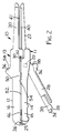
- Figure 1 is a first side view of a surgical stapling instrument according to the present invention showing two assemblies of the instrument separated from each other and having parts broken away to show details;
- Figure 2 is a first side view of the surgical stapling instrument of Figure 1 showing the two assemblies of the instrument engaged with each other in an open position;
- Figure 3 is a second side view of the surgical stapling instrument of Figure 1 showing the two assemblies of the instrument engaged with each other in a closed position;
- Figure 4 is a sectional view taken approximately along line 4-4 of Figure 3;
- Figure 5 is a first side view of the surgical stapling instrument of Figure 1 showing the two assemblies of the instrument engaged with each other in the closed position;
- Figure 6 is an enlarged fragmentary side view of an alternative embodiment of the surgical stapling instrument according to the present invention; and
- Figure 7 is a fragmentary sectional view taken approximately along line 7-7 of Figure 6.
- Referring now to Figures 1 through 5 of the drawing, there is shown a first embodiment of a
surgical stapling instrument 10 according to the present invention, generally designated by thereference numeral 10 and comprising twoseparable assemblies 11 and 13. - Generally the
surgical stapling instrument 10 comprises first and second elongatestructural members handle part jaw part handle part structural members handle parts pins 25 on the secondstructural member 14 and generally U-shapedjournal surfaces 26 on the firststructural member 12 adapted and positioned for free engagement and disengagement in a plane normal to the directions in which thestructural members structural members jaw parts jaw parts elongate locking member 28 having a pivot point at apin 29 closely adjacent a first end of thelocking member 28 is mounted by thepin 29 on the first end of the secondstructural member 14 for pivotal movement around an axis generally normal to said plane between a locking position (Figures 3 and 5) generally aligned with thehandle part 18 of the secondstructural member 14, and a release position (Figures 1 and 2) with the second end of thelocking member 28 spaced from the second end of the secondstructural member 14. The first end of thelocking member 28 and thehandle part 16 of thestructural member 12 adjacent its first end have surfaces provided by two opposite axially parallel outwardly projectingpins 30 on thelocking member 28 and side surfaces of generally U-shapedsurfaces 32 on the firststructural member 12 opening toward the second end of the firststructural member 12 adapted, when the pivot means are engaged with thestructural members locking member 28 from its release position (Figure 2) to its locking position (Figures 3 and 5) to forcefully move thestructural members jaw parts structural members elongate locking member 28 and the secondstructural member 14 are provided (Figure 4) in the form of anedge abutment surface 33 at one end of acam 34 on a cantilevered transverselyflexible part 35 of thelocking member 28 in engagement with anedge abutment surface 36 at one end of acam 37 on the secondstructural member 14 for releasably holding thelocking member 28 in its locking position and thus maintain any compressive forces applied between thejaw parts cams flexible part 35 and allow thecam 34 to pass around thecam 37 to afford engagement of theedge abutment surfaces locking member 28 is manually pressed to its locking position, and theflexible part 35 can be manually deflected by pressing on the flexible part at agrooved pressure pad 38 to afford separation of theabutment surfaces locking member 28 from its locking to its release position. - The second
structural member 14 is adapted to have an elongateremovable anvil 40 positioned over and along thejaw part 22 to form the first assembly 11, and thejaw part 20 of the first structural member has an elongate groove 39 (Figure 1) adapted to receive acartridge body 41 of acartridge assembly 42 to form thesecond assembly 13. Thecartridge body 41 contains a plurality ofstaples 43 disposed in rows oriented longitudinally of thejaw part 20 in opposition to theanvil 40 when thestructural members cartridge assembly 42 includes manually actuatable means including cam likedrivers 45 fixed at one end of adrive rod 44 and adapted to be moved through longitudinal slots in thecartridge body 41 by manually pressing on an actuatingtab 46 fixed at the end of thedrive rod 44 opposite thedrivers 45 for sequentially ejecting the staples from thecartridge body 41 bycamming plungers 47 under thestaples 43 toward a surface of thecartridge body 41 opposite theanvil 40 to thereby press the ejectedstaples 43 against specially shaped surfaces on theanvil 40 to engage and close thestaples 43 in tissues between thejaw parts structural members cartridge assembly 42 can also optionally, as illustrated, include a knife 48 that is also fixed on the end of thedrive rod 44 adjacent thedrivers 45 so that manual movement of thedrivers 45 to eject and close thestaples 43 also moves the knife 48 along thejaw parts anvil 40 to cut tissues between the rows of applied staples. - The structure of the
stapling instrument 10 as described above in this Detailed Description portion of this specification is essentially the same as that of the surgical stapling instrument sold under the trade designation "The ILA Stapler" by Minnesota Mining and Manufacturing Company, St. Paul, Minnesota. The novel structure of thestapling instrument 10 that distinguishes the present invention from "The ILA Stapler" stapling instrument and which allows thestapling instrument 10 to be made in a size that can deliver a 100 millimeter long row of staples is that one of thestructural members 12 or 14 (as illustrated, the first structural member 12) has asupport element 50 about 1/2 inch long in the direction in which thestructural member 12 is elongate, which supportelement 50 is in contact with the other of thestructural members 12 or 14 (as illustrated, the second structural member 14) to the side of aspace 52 defined between thehandle parts structural members structural members structural members support element 50 contacts aplanar surface 54 on the secondstructural member 14 disposed at a right angle to the plane in which thestructural members pins 25 at a position spaced about one quarter the distance between the first and second ends of thehandle parts handle parts jaw parts jaw parts support element 50 is positioned between opposite manuallyengageable projections 56 on the firststructural member 12 andlocking member 28 that haveengagement surfaces 58 disposed at right angles to the length of thestructural members handle parts locking member 28 is in its locking position. Theengagement surfaces 58 can be engaged with the fingers of a user's hand while the thumb of that hand is used to press the actuatingtab 46 toward thejaw parts jaw parts structural members handle parts member 28 between their second ends and the adjacent sides of theprojections 56 so that the location of thesupport element 50 between theprojections 56 limits the possibility that a part of a user's glove or skin will become entrapped between thesupport element 50 and the secondstructural member 14. - Referring now to Figures 6 and 7 there is shown an optional structure for a
support element 60 on astructural member 62 that can otherwise have the same structure as the firststructural member 12, and for the portion of astructural member 64 thesupport element 60 engages, whichstructural member 64 may otherwise have the same structure as he secondstructural member 14. Thestructural member 64 contacted by thesupport element 60 has surfaces defining asocket 66, and a distal end portion of thesupport element 60 engages the surfaces defining thesocket 66 when thestructural members support element 60 with the surfaces defining thesocket 66 not only restricts deflection of the handle parts of thestructural members space 68 therebetween, but also prevents any transverse deflection of those handle parts in a direction at right angles to the plane in which thestructural members structural members - The present invention has now been described with reference to two embodiments thereof. It will be apparent to those skilled in the art that many changes can be made in the embodiments described without departing from the scope of the present invention, including the location of the support element between the first and second ends of the handle parts of surgical stapling instrument. Thus the scope of the present invention should not be limited to the structures descried in this application, but only by structures described by the language of the claims and the equivalents of those structures.
Claims (6)
- A surgical stapling instrument (10) comprising:
first and second proximal portions (16, 18) that are elongate in a first direction,
a distal portion that is elongate in the first direction and which defines a longitudinal direction, said distal portion having a pair of jaws (20, 22) projecting away from said proximal portions (16, 18),
said jaws (20, 22) having proximal and distal ends,
closing means (25) for affording movement of said distal ends of said jaws (20, 22) between a closed position (Figs. 3 and 5) with said jaws (20, 22) in closely spaced relationship adapted to clamp tissue therebetween, and an open position (Fig. 2) with said jaws (20, 22) spaced farther from each other than in said closed position,
one of said jaws (22) comprising an anvil (40) positioned along the jaw (22) and the other of said jaws (20) having a plurality of staples (43) disposed in rows oriented longitudinally of the jaw part (20) in opposition to the anvil (40) when the jaws (20, 22) are in the closed position,
said stapler (10) including firing means for sequentially ejecting said staples (43) from the jaw part (20) by camming a plurality of plungers (47) adjacent the staples (43) toward a surface of the jaw part (20) opposite the anvil (40) to thereby press the ejected staples (43) against specially shaped surfaces on the anvil (40) to engage and close the staples (43) in tissue between the jaws (20 and 22) when the jaws (20 and 22) are in the closed position,
said firing means comprising at least one driver (45) adapted to be moved in a longitudinal slot in the jaw part (20),
a deflection pivot means (30, 32) about which tissue placed between the jaws (20, 22) urges the jaws (20, 22) to pivot, when the jaws (20 and 22) are moved to the closed position with the tissue placed therebetween; and
the stapling instrument (10) being characterized in that one of said proximal portions (16) has a support element (50; 60) in contact with a portion (54; 64) of the other of said proximal portions (18) when said jaws (20, 22) are in said closed position (Figs. 3 and 5), said support element (50; 60) being spaced proximal of said deflection pivot means (30, 32) to restrict bending deflection of said proximal portions (16, 18) toward each other in response to separating forces applied to said jaws (20, 22) by tissues compressed between said jaws (20, 22), thereby to restrict bending of the jaws (20, 22) away from each other in response to the separating forces applied to the jaws (20, 22) by compressed tissue. - A surgical stapling instrument (10) according to claim 1, wherein:
said first and second proximal portions (16 and 18) have a pair of ends, and
said support element (50, 60) being spaced between said ends of said first and second proximal portions (16, 18). - A surgical stapling instrument (10) according to claims 1 or 2 further characterized in that when said jaws (20, 22) are in said closed position (Figs. 3 and 5), said support element (50) contacts a planar surface (54).
- A surgical stapling instrument (10) according to claims 1, 2 or 3 further characterized in that said proximal portion (18) contacted by said support element (60) has surfaces defining a socket (66), and a distal end portion of said support element (60) engages said surfaces defining said socket (66) when said jaws (20, 22) are in said closed position (Figs. 6 and 7).
- A surgical stapling instrument (10) according to claims 1 or 2 further characterized in that said support element (50; 60) is spaced proximally away from said deflection pivot means (30, 32).
- A surgical stapling instrument (10) according to claims 1 or 2 wherein said deflection pivot means (30, 32) is situated longitudinally between said proximal portions (16, 18) and said jaws (20, 22).
Applications Claiming Priority (3)
| Application Number | Priority Date | Filing Date | Title |
|---|---|---|---|
| US166037 | 1988-03-09 | ||
| US07/166,037 US4863088A (en) | 1988-03-09 | 1988-03-09 | Surgical stapling instrument |
| EP89302292A EP0332413B1 (en) | 1988-03-09 | 1989-03-08 | Surgical stapling instrument |
Related Parent Applications (1)
| Application Number | Title | Priority Date | Filing Date |
|---|---|---|---|
| EP89302292.1 Division | 1989-03-08 |
Publications (2)
| Publication Number | Publication Date |
|---|---|
| EP0609906A2 true EP0609906A2 (en) | 1994-08-10 |
| EP0609906A3 EP0609906A3 (en) | 1994-09-14 |
Family
ID=22601544
Family Applications (2)
| Application Number | Title | Priority Date | Filing Date |
|---|---|---|---|
| EP89302292A Expired - Lifetime EP0332413B1 (en) | 1988-03-09 | 1989-03-08 | Surgical stapling instrument |
| EP9494103433A Withdrawn EP0609906A3 (en) | 1988-03-09 | 1989-03-08 | Surgical stapling instrument. |
Family Applications Before (1)
| Application Number | Title | Priority Date | Filing Date |
|---|---|---|---|
| EP89302292A Expired - Lifetime EP0332413B1 (en) | 1988-03-09 | 1989-03-08 | Surgical stapling instrument |
Country Status (5)
| Country | Link |
|---|---|
| US (1) | US4863088A (en) |
| EP (2) | EP0332413B1 (en) |
| JP (1) | JP2656826B2 (en) |
| CA (1) | CA1313605C (en) |
| DE (1) | DE68918615T2 (en) |
Families Citing this family (264)
| Publication number | Priority date | Publication date | Assignee | Title |
|---|---|---|---|---|
| US5653373A (en) * | 1990-09-17 | 1997-08-05 | United States Surgical Corporation | Arcuate apparatus for applying two-part surgical fasteners |
| US5253793A (en) * | 1990-09-17 | 1993-10-19 | United States Surgical Corporation | Apparatus for applying two-part surgical fasteners |
| US5156315A (en) * | 1990-09-17 | 1992-10-20 | United States Surgical Corporation | Arcuate apparatus for applying two-part surgical fasteners |
| US5156614A (en) * | 1990-09-17 | 1992-10-20 | United States Surgical Corporation | Apparatus for applying two-part surgical fasteners |
| US5129570A (en) * | 1990-11-30 | 1992-07-14 | Ethicon, Inc. | Surgical stapler |
| CA2055943C (en) * | 1990-12-06 | 2003-09-23 | Daniel P. Rodak | Surgical fastening apparatus with locking mechanism |
| US5470009A (en) * | 1990-12-06 | 1995-11-28 | United States Surgical Corporation | Surgical fastening apparatus with locking mechanism |
| US5141144A (en) * | 1990-12-18 | 1992-08-25 | Minnesota Mining And Manufacturing Company | Stapler and firing device |
| DE69119607T2 (en) * | 1990-12-18 | 1996-11-14 | United States Surgical Corp | SAFETY DEVICE FOR SURGICAL CLAMPING DEVICES |
| US5083695A (en) * | 1990-12-18 | 1992-01-28 | Minnesota Mining And Manufacturing Company | Stapler and firing device |
| US5065929A (en) * | 1991-04-01 | 1991-11-19 | Ethicon, Inc. | Surgical stapler with locking means |
| US5413267A (en) * | 1991-05-14 | 1995-05-09 | United States Surgical Corporation | Surgical stapler with spent cartridge sensing and lockout means |
| CA2075141C (en) * | 1991-10-17 | 1998-06-30 | Donald A. Morin | Anvil for surgical staplers |
| CA2078794C (en) * | 1991-10-18 | 1998-10-06 | Frank J. Viola | Locking device for an apparatus for applying surgical fasteners |
| US5307976A (en) * | 1991-10-18 | 1994-05-03 | Ethicon, Inc. | Linear stapling mechanism with cutting means |
| US5514157A (en) | 1992-02-12 | 1996-05-07 | United States Surgical Corporation | Articulating endoscopic surgical apparatus |
| US5423471A (en) * | 1992-10-02 | 1995-06-13 | United States Surgical Corporation | Apparatus for applying two-part surgical fasteners in laparoscopic or endoscopic procedures |
| US5573169A (en) * | 1992-10-02 | 1996-11-12 | United States Surgical Corporation | Apparatus for applying two-part surgical fasteners in laparoscopic or endoscopic procedures |
| US6716232B1 (en) | 1993-04-30 | 2004-04-06 | United States Surgical Corporation | Surgical instrument having an articulated jaw structure and a detachable knife |
| US5447265A (en) * | 1993-04-30 | 1995-09-05 | Minnesota Mining And Manufacturing Company | Laparoscopic surgical instrument with a mechanism for preventing its entry into the abdominal cavity once it is depleted and removed from the abdominal cavity |
| US5470008A (en) * | 1993-12-20 | 1995-11-28 | United States Surgical Corporation | Apparatus for applying surgical fasteners |
| WO1995023557A1 (en) * | 1994-03-01 | 1995-09-08 | United States Surgical Corporation | Surgical stapler with anvil sensor and lockout |
| US5489058A (en) * | 1994-05-02 | 1996-02-06 | Minnesota Mining And Manufacturing Company | Surgical stapler with mechanisms for reducing the firing force |
| US5470007A (en) * | 1994-05-02 | 1995-11-28 | Minnesota Mining And Manufacturing Company | Laparoscopic stapler with overload sensor and interlock |
| US6704210B1 (en) | 1994-05-20 | 2004-03-09 | Medtronic, Inc. | Bioprothesis film strip for surgical stapler and method of attaching the same |
| US5636779A (en) * | 1994-12-13 | 1997-06-10 | United States Surgical Corporation | Apparatus for applying surgical fasteners |
| US5988479A (en) * | 1994-12-13 | 1999-11-23 | United States Surgical Corporation | Apparatus for applying surgical fasteners |
| US5718359A (en) * | 1995-08-14 | 1998-02-17 | United States Of America Surgical Corporation | Surgical stapler with lockout mechanism |
| US5715988A (en) * | 1995-08-14 | 1998-02-10 | United States Surgical Corporation | Surgical stapler with lockout mechanism |
| US5762256A (en) | 1995-08-28 | 1998-06-09 | United States Surgical Corporation | Surgical stapler |
| US5782396A (en) | 1995-08-28 | 1998-07-21 | United States Surgical Corporation | Surgical stapler |
| US6032849A (en) * | 1995-08-28 | 2000-03-07 | United States Surgical | Surgical stapler |
| US5941442A (en) * | 1995-10-27 | 1999-08-24 | United States Surgical | Surgical stapler |
| US5651491A (en) * | 1995-10-27 | 1997-07-29 | United States Surgical Corporation | Surgical stapler having interchangeable loading units |
| US5911352A (en) * | 1996-12-17 | 1999-06-15 | United States Surgical Corporation | Surgical stapling apparatus |
| US5865361A (en) | 1997-09-23 | 1999-02-02 | United States Surgical Corporation | Surgical stapling apparatus |
| US7695485B2 (en) | 2001-11-30 | 2010-04-13 | Power Medical Interventions, Llc | Surgical device |
| US8025199B2 (en) | 2004-02-23 | 2011-09-27 | Tyco Healthcare Group Lp | Surgical cutting and stapling device |
| US6264087B1 (en) | 1999-07-12 | 2001-07-24 | Powermed, Inc. | Expanding parallel jaw device for use with an electromechanical driver device |
| US7951071B2 (en) | 1999-06-02 | 2011-05-31 | Tyco Healthcare Group Lp | Moisture-detecting shaft for use with an electro-mechanical surgical device |
| US6716233B1 (en) | 1999-06-02 | 2004-04-06 | Power Medical Interventions, Inc. | Electromechanical driver and remote surgical instrument attachment having computer assisted control capabilities |
| US7803151B2 (en) | 2001-12-04 | 2010-09-28 | Power Medical Interventions, Llc | System and method for calibrating a surgical instrument |
| US8016855B2 (en) | 2002-01-08 | 2011-09-13 | Tyco Healthcare Group Lp | Surgical device |
| US7334717B2 (en) | 2001-10-05 | 2008-02-26 | Tyco Healthcare Group Lp | Surgical fastener applying apparatus |
| US6592597B2 (en) * | 2001-05-07 | 2003-07-15 | Ethicon Endo-Surgery, Inc. | Adhesive for attaching buttress material to a surgical fastening device |
| CA2695579C (en) | 2001-10-05 | 2012-09-25 | Tyco Healthcare Group Lp | Surgical stapling device |
| JP4245480B2 (en) | 2001-10-05 | 2009-03-25 | タイコ ヘルスケア グループ エルピー | Surgical stapling apparatus and method |
| US9113878B2 (en) | 2002-01-08 | 2015-08-25 | Covidien Lp | Pinion clip for right angle linear cutter |
| EP1503671B1 (en) | 2002-05-10 | 2006-10-11 | Tyco Healthcare Group Lp | Wound closure material applicator and stapler |
| CA2489727C (en) | 2002-06-14 | 2011-04-26 | Power Medical Interventions, Inc. | Surgical device |
| JP4448449B2 (en) | 2002-10-04 | 2010-04-07 | タイコ ヘルスケア グループ エルピー | Tool assembly for a surgical stapling device |
| ES2730694T3 (en) | 2002-10-04 | 2019-11-12 | Covidien Lp | Surgical stapler with universal joint and prior tissue support |
| EP2238917B1 (en) | 2002-10-04 | 2012-12-05 | Tyco Healthcare Group LP | Tool assembly for a surgical stapling device |
| US20040243151A1 (en) | 2003-04-29 | 2004-12-02 | Demmy Todd L. | Surgical stapling device with dissecting tip |
| US9597078B2 (en) | 2003-04-29 | 2017-03-21 | Covidien Lp | Surgical stapling device with dissecting tip |
| US7494039B2 (en) | 2003-06-17 | 2009-02-24 | Tyco Healthcare Group Lp | Surgical stapling device |
| JP4664909B2 (en) | 2003-06-17 | 2011-04-06 | タイコ ヘルスケア グループ リミテッド パートナーシップ | Surgical stapling device |
| US7468041B2 (en) * | 2003-06-26 | 2008-12-23 | Depuy Products, Inc. | Modular surgical instrument with reciprocable implement |
| CA2542532C (en) | 2003-10-17 | 2012-08-14 | Tyco Healthcare Group, Lp | Surgical stapling device with independent tip rotation |
| US7296722B2 (en) | 2003-10-17 | 2007-11-20 | Tyco Healthcare Group Lp | Surgical fastener applying apparatus with controlled beam deflection |
| US7886952B2 (en) * | 2004-02-17 | 2011-02-15 | Tyco Healthcare Group Lp | Surgical stapling apparatus with locking mechanism |
| US7143924B2 (en) | 2004-02-17 | 2006-12-05 | Tyco Healthcare Group Lp | Surgical stapling apparatus with locking mechanism |
| DE602005001328T2 (en) | 2004-02-17 | 2008-02-14 | Tyco Healthcare Group Lp, Norwalk | Surgical stapler |
| ES2285586T3 (en) | 2004-02-17 | 2007-11-16 | Tyco Healthcare Group Lp | SURGICAL ENGRAVING DEVICE WITH LOCKING MECHANISM. |
| EP1563794B1 (en) * | 2004-02-17 | 2007-04-25 | Tyco Healthcare Group Lp | Surgical stapling apparatus with locking mechanism |
| JP4686985B2 (en) * | 2004-02-27 | 2011-05-25 | コニカミノルタエムジー株式会社 | Actinic ray curable ink, image forming method, and ink jet recording apparatus |
| US9138226B2 (en) | 2005-03-30 | 2015-09-22 | Covidien Lp | Cartridge assembly for a surgical stapling device |
| US7780055B2 (en) | 2005-04-06 | 2010-08-24 | Tyco Healthcare Group Lp | Loading unit having drive assembly locking mechanism |
| CA2563147C (en) | 2005-10-14 | 2014-09-23 | Tyco Healthcare Group Lp | Surgical stapling device |
| US8708210B2 (en) | 2006-10-05 | 2014-04-29 | Covidien Lp | Method and force-limiting handle mechanism for a surgical instrument |
| US7866525B2 (en) | 2006-10-06 | 2011-01-11 | Tyco Healthcare Group Lp | Surgical instrument having a plastic surface |
| US7845535B2 (en) | 2006-10-06 | 2010-12-07 | Tyco Healthcare Group Lp | Surgical instrument having a plastic surface |
| WO2008089302A1 (en) * | 2007-01-17 | 2008-07-24 | United States Of America As Represented By The Administrator Of The National Aeronautics And Space Administration | Wireless sensing system for non-invasive monitoring of attributes of contents in a container |
| US7624902B2 (en) | 2007-08-31 | 2009-12-01 | Tyco Healthcare Group Lp | Surgical stapling apparatus |
| US8061576B2 (en) | 2007-08-31 | 2011-11-22 | Tyco Healthcare Group Lp | Surgical instrument |
| ES2534292T5 (en) | 2007-09-21 | 2018-07-04 | Covidien Lp | Surgical device |
| WO2009039510A1 (en) | 2007-09-21 | 2009-03-26 | Power Medical Interventions, Inc. | Surgical device |
| US7954685B2 (en) | 2007-11-06 | 2011-06-07 | Tyco Healthcare Group Lp | Articulation and firing force mechanisms |
| US8701959B2 (en) | 2008-06-06 | 2014-04-22 | Covidien Lp | Mechanically pivoting cartridge channel for surgical instrument |
| US7789283B2 (en) | 2008-06-06 | 2010-09-07 | Tyco Healthcare Group Lp | Knife/firing rod connection for surgical instrument |
| US7942303B2 (en) | 2008-06-06 | 2011-05-17 | Tyco Healthcare Group Lp | Knife lockout mechanisms for surgical instrument |
| US7896214B2 (en) | 2008-09-23 | 2011-03-01 | Tyco Healthcare Group Lp | Tissue stop for surgical instrument |
| US8215532B2 (en) | 2008-09-23 | 2012-07-10 | Tyco Healthcare Group Lp | Tissue stop for surgical instrument |
| US7988028B2 (en) | 2008-09-23 | 2011-08-02 | Tyco Healthcare Group Lp | Surgical instrument having an asymmetric dynamic clamping member |
| US8628544B2 (en) | 2008-09-23 | 2014-01-14 | Covidien Lp | Knife bar for surgical instrument |
| US7963197B2 (en) * | 2008-11-28 | 2011-06-21 | Steven Starko | Plumbing tool |
| US8292154B2 (en) | 2009-04-16 | 2012-10-23 | Tyco Healthcare Group Lp | Surgical apparatus for applying tissue fasteners |
| US8127976B2 (en) | 2009-05-08 | 2012-03-06 | Tyco Healthcare Group Lp | Stapler cartridge and channel interlock |
| US8132706B2 (en) | 2009-06-05 | 2012-03-13 | Tyco Healthcare Group Lp | Surgical stapling apparatus having articulation mechanism |
| US8205779B2 (en) | 2009-07-23 | 2012-06-26 | Tyco Healthcare Group Lp | Surgical stapler with tactile feedback system |
| US8342378B2 (en) | 2009-08-17 | 2013-01-01 | Covidien Lp | One handed stapler |
| US8225979B2 (en) | 2009-10-30 | 2012-07-24 | Tyco Healthcare Group Lp | Locking shipping wedge |
| US8418907B2 (en) | 2009-11-05 | 2013-04-16 | Covidien Lp | Surgical stapler having cartridge with adjustable cam mechanism |
| US8348127B2 (en) | 2010-04-07 | 2013-01-08 | Covidien Lp | Surgical fastener applying apparatus |
| US8899461B2 (en) | 2010-10-01 | 2014-12-02 | Covidien Lp | Tissue stop for surgical instrument |
| US8308041B2 (en) | 2010-11-10 | 2012-11-13 | Tyco Healthcare Group Lp | Staple formed over the wire wound closure procedure |
| US8397972B2 (en) | 2011-03-18 | 2013-03-19 | Covidien Lp | Shipping wedge with lockout |
| US9271728B2 (en) | 2011-06-09 | 2016-03-01 | Covidien Lp | Surgical fastener applying apparatus |
| US9451959B2 (en) * | 2011-06-09 | 2016-09-27 | Covidien Lp | Surgical fastener applying apparatus |
| US9289209B2 (en) | 2011-06-09 | 2016-03-22 | Covidien Lp | Surgical fastener applying apparatus |
| US8763876B2 (en) | 2011-06-30 | 2014-07-01 | Covidien Lp | Surgical instrument and cartridge for use therewith |
| US20130012958A1 (en) | 2011-07-08 | 2013-01-10 | Stanislaw Marczyk | Surgical Device with Articulation and Wrist Rotation |
| US9539007B2 (en) | 2011-08-08 | 2017-01-10 | Covidien Lp | Surgical fastener applying aparatus |
| US9155537B2 (en) | 2011-08-08 | 2015-10-13 | Covidien Lp | Surgical fastener applying apparatus |
| US9724095B2 (en) | 2011-08-08 | 2017-08-08 | Covidien Lp | Surgical fastener applying apparatus |
| US9016539B2 (en) | 2011-10-25 | 2015-04-28 | Covidien Lp | Multi-use loading unit |
| US8740036B2 (en) | 2011-12-01 | 2014-06-03 | Covidien Lp | Surgical instrument with actuator spring arm |
| US10299815B2 (en) | 2012-01-19 | 2019-05-28 | Covidien Lp | Surgical instrument with clam releases mechanism |
| US8864010B2 (en) | 2012-01-20 | 2014-10-21 | Covidien Lp | Curved guide member for articulating instruments |
| US8979827B2 (en) | 2012-03-14 | 2015-03-17 | Covidien Lp | Surgical instrument with articulation mechanism |
| US9113881B2 (en) | 2012-03-16 | 2015-08-25 | Covidien Lp | Travel clip for surgical staple cartridge |
| US9526497B2 (en) | 2012-05-07 | 2016-12-27 | Covidien Lp | Surgical instrument with articulation mechanism |
| US9232944B2 (en) | 2012-06-29 | 2016-01-12 | Covidien Lp | Surgical instrument and bushing |
| US9364217B2 (en) | 2012-10-16 | 2016-06-14 | Covidien Lp | In-situ loaded stapler |
| US9345480B2 (en) | 2013-01-18 | 2016-05-24 | Covidien Lp | Surgical instrument and cartridge members for use therewith |
| US10561432B2 (en) | 2013-03-05 | 2020-02-18 | Covidien Lp | Pivoting screw for use with a pair of jaw members of a surgical instrument |
| US9814463B2 (en) | 2013-03-13 | 2017-11-14 | Covidien Lp | Surgical stapling apparatus |
| US9629628B2 (en) | 2013-03-13 | 2017-04-25 | Covidien Lp | Surgical stapling apparatus |
| US9668728B2 (en) | 2013-03-13 | 2017-06-06 | Covidien Lp | Surgical stapling apparatus |
| US9717498B2 (en) | 2013-03-13 | 2017-08-01 | Covidien Lp | Surgical stapling apparatus |
| US9510827B2 (en) | 2013-03-25 | 2016-12-06 | Covidien Lp | Micro surgical instrument and loading unit for use therewith |
| US9445810B2 (en) | 2013-06-12 | 2016-09-20 | Covidien Lp | Stapling device with grasping jaw mechanism |
| US9662108B2 (en) | 2013-08-30 | 2017-05-30 | Covidien Lp | Surgical stapling apparatus |
| US11033264B2 (en) | 2013-11-04 | 2021-06-15 | Covidien Lp | Surgical fastener applying apparatus |
| CA2926748A1 (en) | 2013-11-04 | 2015-05-07 | Covidien Lp | Surgical fastener applying apparatus |
| CN105682568B (en) | 2013-11-04 | 2018-10-23 | 柯惠Lp公司 | Surgical fasteners bringing device |
| WO2015090157A1 (en) * | 2013-12-17 | 2015-06-25 | 苏州天臣国际医疗科技有限公司 | Linear cutting stapler |
| US9867613B2 (en) | 2013-12-19 | 2018-01-16 | Covidien Lp | Surgical staples and end effectors for deploying the same |
| US9629627B2 (en) | 2014-01-28 | 2017-04-25 | Coviden Lp | Surgical apparatus |
| US9936952B2 (en) | 2014-02-03 | 2018-04-10 | Covidien Lp | Introducer assembly for a surgical fastener applying apparatus |
| US9848874B2 (en) | 2014-02-14 | 2017-12-26 | Covidien Lp | Small diameter endoscopic stapler |
| US9707005B2 (en) | 2014-02-14 | 2017-07-18 | Ethicon Llc | Lockout mechanisms for surgical devices |
| US9757126B2 (en) | 2014-03-31 | 2017-09-12 | Covidien Lp | Surgical stapling apparatus with firing lockout mechanism |
| US9668733B2 (en) | 2014-04-21 | 2017-06-06 | Covidien Lp | Stapling device with features to prevent inadvertent firing of staples |
| US9861366B2 (en) | 2014-05-06 | 2018-01-09 | Covidien Lp | Ejecting assembly for a surgical stapler |
| WO2015174985A1 (en) | 2014-05-15 | 2015-11-19 | Lp Covidien | Surgical fastener applying apparatus |
| US10039545B2 (en) | 2015-02-23 | 2018-08-07 | Covidien Lp | Double fire stapling |
| US10085749B2 (en) | 2015-02-26 | 2018-10-02 | Covidien Lp | Surgical apparatus with conductor strain relief |
| US10285698B2 (en) | 2015-02-26 | 2019-05-14 | Covidien Lp | Surgical apparatus |
| US9918717B2 (en) | 2015-03-18 | 2018-03-20 | Covidien Lp | Pivot mechanism for surgical device |
| US10463368B2 (en) | 2015-04-10 | 2019-11-05 | Covidien Lp | Endoscopic stapler |
| US10117650B2 (en) | 2015-05-05 | 2018-11-06 | Covidien Lp | Adapter assembly and loading units for surgical stapling devices |
| US10299789B2 (en) | 2015-05-05 | 2019-05-28 | Covidie LP | Adapter assembly for surgical stapling devices |
| US10039532B2 (en) | 2015-05-06 | 2018-08-07 | Covidien Lp | Surgical instrument with articulation assembly |
| JP6420501B6 (en) | 2015-05-08 | 2018-12-19 | ジャストライト サージカル,リミティド ライアビリティ カンパニー | Surgical stapler |
| US10349941B2 (en) | 2015-05-27 | 2019-07-16 | Covidien Lp | Multi-fire lead screw stapling device |
| US10172615B2 (en) | 2015-05-27 | 2019-01-08 | Covidien Lp | Multi-fire push rod stapling device |
| US10548599B2 (en) | 2015-07-20 | 2020-02-04 | Covidien Lp | Endoscopic stapler and staple |
| US9987012B2 (en) | 2015-07-21 | 2018-06-05 | Covidien Lp | Small diameter cartridge design for a surgical stapling instrument |
| US10064622B2 (en) | 2015-07-29 | 2018-09-04 | Covidien Lp | Surgical stapling loading unit with stroke counter and lockout |
| US10045782B2 (en) | 2015-07-30 | 2018-08-14 | Covidien Lp | Surgical stapling loading unit with stroke counter and lockout |
| US10213204B2 (en) | 2015-10-02 | 2019-02-26 | Covidien Lp | Micro surgical instrument and loading unit for use therewith |
| US10772632B2 (en) | 2015-10-28 | 2020-09-15 | Covidien Lp | Surgical stapling device with triple leg staples |
| US10595864B2 (en) | 2015-11-24 | 2020-03-24 | Covidien Lp | Adapter assembly for interconnecting electromechanical surgical devices and surgical loading units, and surgical systems thereof |
| US10111660B2 (en) | 2015-12-03 | 2018-10-30 | Covidien Lp | Surgical stapler flexible distal tip |
| US10966717B2 (en) | 2016-01-07 | 2021-04-06 | Covidien Lp | Surgical fastener apparatus |
| US10660623B2 (en) | 2016-01-15 | 2020-05-26 | Covidien Lp | Centering mechanism for articulation joint |
| US10349937B2 (en) | 2016-02-10 | 2019-07-16 | Covidien Lp | Surgical stapler with articulation locking mechanism |
| US10420559B2 (en) | 2016-02-11 | 2019-09-24 | Covidien Lp | Surgical stapler with small diameter endoscopic portion |
| US10561419B2 (en) | 2016-05-04 | 2020-02-18 | Covidien Lp | Powered end effector assembly with pivotable channel |
| US11065022B2 (en) | 2016-05-17 | 2021-07-20 | Covidien Lp | Cutting member for a surgical instrument |
| US10631857B2 (en) | 2016-11-04 | 2020-04-28 | Covidien Lp | Loading unit for surgical instruments with low profile pushers |
| US11642126B2 (en) | 2016-11-04 | 2023-05-09 | Covidien Lp | Surgical stapling apparatus with tissue pockets |
| US10492784B2 (en) | 2016-11-08 | 2019-12-03 | Covidien Lp | Surgical tool assembly with compact firing assembly |
| US10463371B2 (en) | 2016-11-29 | 2019-11-05 | Covidien Lp | Reload assembly with spent reload indicator |
| US10709901B2 (en) | 2017-01-05 | 2020-07-14 | Covidien Lp | Implantable fasteners, applicators, and methods for brachytherapy |
| US10952767B2 (en) | 2017-02-06 | 2021-03-23 | Covidien Lp | Connector clip for securing an introducer to a surgical fastener applying apparatus |
| US20180235618A1 (en) | 2017-02-22 | 2018-08-23 | Covidien Lp | Loading unit for surgical instruments with low profile pushers |
| US10849621B2 (en) | 2017-02-23 | 2020-12-01 | Covidien Lp | Surgical stapler with small diameter endoscopic portion |
| US11350915B2 (en) | 2017-02-23 | 2022-06-07 | Covidien Lp | Surgical stapler with small diameter endoscopic portion |
| US10299790B2 (en) | 2017-03-03 | 2019-05-28 | Covidien Lp | Adapter with centering mechanism for articulation joint |
| US10660641B2 (en) | 2017-03-16 | 2020-05-26 | Covidien Lp | Adapter with centering mechanism for articulation joint |
| US10603035B2 (en) | 2017-05-02 | 2020-03-31 | Covidien Lp | Surgical loading unit including an articulating end effector |
| US11324502B2 (en) | 2017-05-02 | 2022-05-10 | Covidien Lp | Surgical loading unit including an articulating end effector |
| US10524784B2 (en) | 2017-05-05 | 2020-01-07 | Covidien Lp | Surgical staples with expandable backspan |
| US10390826B2 (en) | 2017-05-08 | 2019-08-27 | Covidien Lp | Surgical stapling device with elongated tool assembly and methods of use |
| US10420551B2 (en) | 2017-05-30 | 2019-09-24 | Covidien Lp | Authentication and information system for reusable surgical instruments |
| US10478185B2 (en) | 2017-06-02 | 2019-11-19 | Covidien Lp | Tool assembly with minimal dead space |
| US10624636B2 (en) | 2017-08-23 | 2020-04-21 | Covidien Lp | Surgical stapling device with floating staple cartridge |
| US10806452B2 (en) | 2017-08-24 | 2020-10-20 | Covidien Lp | Loading unit for a surgical stapling instrument |
| US10925603B2 (en) | 2017-11-14 | 2021-02-23 | Covidien Lp | Reload with articulation stabilization system |
| US10863987B2 (en) | 2017-11-16 | 2020-12-15 | Covidien Lp | Surgical instrument with imaging device |
| US10945732B2 (en) | 2018-01-17 | 2021-03-16 | Covidien Lp | Surgical stapler with self-returning assembly |
| EP3758618A4 (en) | 2018-03-02 | 2021-10-06 | Covidien LP | Surgical stapling instrument |
| US10849622B2 (en) | 2018-06-21 | 2020-12-01 | Covidien Lp | Articulated stapling with fire lock |
| US10736631B2 (en) | 2018-08-07 | 2020-08-11 | Covidien Lp | End effector with staple cartridge ejector |
| US10898187B2 (en) | 2018-08-13 | 2021-01-26 | Ethicon Llc | Firing system for linear surgical stapler |
| US11033266B2 (en) * | 2018-08-13 | 2021-06-15 | Cilag Gmbh International | Decoupling mechanism for linear surgical stapler |
| US10849620B2 (en) | 2018-09-14 | 2020-12-01 | Covidien Lp | Connector mechanisms for surgical stapling instruments |
| US11510669B2 (en) | 2020-09-29 | 2022-11-29 | Covidien Lp | Hand-held surgical instruments |
| US11090051B2 (en) | 2018-10-23 | 2021-08-17 | Covidien Lp | Surgical stapling device with floating staple cartridge |
| US11197673B2 (en) | 2018-10-30 | 2021-12-14 | Covidien Lp | Surgical stapling instruments and end effector assemblies thereof |
| US10912563B2 (en) | 2019-01-02 | 2021-02-09 | Covidien Lp | Stapling device including tool assembly stabilizing member |
| US11344297B2 (en) | 2019-02-28 | 2022-05-31 | Covidien Lp | Surgical stapling device with independently movable jaws |
| US11259808B2 (en) | 2019-03-13 | 2022-03-01 | Covidien Lp | Tool assemblies with a gap locking member |
| US11284892B2 (en) | 2019-04-01 | 2022-03-29 | Covidien Lp | Loading unit and adapter with modified coupling assembly |
| US11284893B2 (en) | 2019-04-02 | 2022-03-29 | Covidien Lp | Stapling device with articulating tool assembly |
| US11241228B2 (en) | 2019-04-05 | 2022-02-08 | Covidien Lp | Surgical instrument including an adapter assembly and an articulating surgical loading unit |
| US11224424B2 (en) | 2019-08-02 | 2022-01-18 | Covidien Lp | Linear stapling device with vertically movable knife |
| US11406385B2 (en) | 2019-10-11 | 2022-08-09 | Covidien Lp | Stapling device with a gap locking member |
| US11123068B2 (en) | 2019-11-08 | 2021-09-21 | Covidien Lp | Surgical staple cartridge |
| US11534163B2 (en) | 2019-11-21 | 2022-12-27 | Covidien Lp | Surgical stapling instruments |
| US11707274B2 (en) | 2019-12-06 | 2023-07-25 | Covidien Lp | Articulating mechanism for surgical instrument |
| US11109862B2 (en) | 2019-12-12 | 2021-09-07 | Covidien Lp | Surgical stapling device with flexible shaft |
| US11737747B2 (en) | 2019-12-17 | 2023-08-29 | Covidien Lp | Hand-held surgical instruments |
| US11452524B2 (en) | 2020-01-31 | 2022-09-27 | Covidien Lp | Surgical stapling device with lockout |
| US11278282B2 (en) | 2020-01-31 | 2022-03-22 | Covidien Lp | Stapling device with selective cutting |
| US11890014B2 (en) | 2020-02-14 | 2024-02-06 | Covidien Lp | Cartridge holder for surgical staples and having ridges in peripheral walls for gripping tissue |
| US11344301B2 (en) | 2020-03-02 | 2022-05-31 | Covidien Lp | Surgical stapling device with replaceable reload assembly |
| US11344302B2 (en) | 2020-03-05 | 2022-05-31 | Covidien Lp | Articulation mechanism for surgical stapling device |
| US11707278B2 (en) | 2020-03-06 | 2023-07-25 | Covidien Lp | Surgical stapler tool assembly to minimize bleeding |
| US11246593B2 (en) | 2020-03-06 | 2022-02-15 | Covidien Lp | Staple cartridge |
| US11317911B2 (en) | 2020-03-10 | 2022-05-03 | Covidien Lp | Tool assembly with replaceable cartridge assembly |
| US11357505B2 (en) | 2020-03-10 | 2022-06-14 | Covidien Lp | Surgical stapling apparatus with firing lockout mechanism |
| US11406383B2 (en) | 2020-03-17 | 2022-08-09 | Covidien Lp | Fire assisted powered EGIA handle |
| US11426159B2 (en) | 2020-04-01 | 2022-08-30 | Covidien Lp | Sled detection device |
| US11331098B2 (en) | 2020-04-01 | 2022-05-17 | Covidien Lp | Sled detection device |
| US11504117B2 (en) | 2020-04-02 | 2022-11-22 | Covidien Lp | Hand-held surgical instruments |
| US11937794B2 (en) | 2020-05-11 | 2024-03-26 | Covidien Lp | Powered handle assembly for surgical devices |
| US11406387B2 (en) | 2020-05-12 | 2022-08-09 | Covidien Lp | Surgical stapling device with replaceable staple cartridge |
| US11191537B1 (en) | 2020-05-12 | 2021-12-07 | Covidien Lp | Stapling device with continuously parallel jaws |
| US11534167B2 (en) | 2020-05-28 | 2022-12-27 | Covidien Lp | Electrotaxis-conducive stapling |
| US11191538B1 (en) | 2020-06-08 | 2021-12-07 | Covidien Lp | Surgical stapling device with parallel jaw closure |
| US11844517B2 (en) | 2020-06-25 | 2023-12-19 | Covidien Lp | Linear stapling device with continuously parallel jaws |
| US11324500B2 (en) | 2020-06-30 | 2022-05-10 | Covidien Lp | Surgical stapling device |
| US11517305B2 (en) | 2020-07-09 | 2022-12-06 | Covidien Lp | Contoured staple pusher |
| US11446028B2 (en) | 2020-07-09 | 2022-09-20 | Covidien Lp | Tool assembly with pivotable clamping beam |
| US11266402B2 (en) | 2020-07-30 | 2022-03-08 | Covidien Lp | Sensing curved tip for surgical stapling instruments |
| US11439392B2 (en) | 2020-08-03 | 2022-09-13 | Covidien Lp | Surgical stapling device and fastener for pathological exam |
| US11395654B2 (en) | 2020-08-07 | 2022-07-26 | Covidien Lp | Surgical stapling device with articulation braking assembly |
| US11602342B2 (en) | 2020-08-27 | 2023-03-14 | Covidien Lp | Surgical stapling device with laser probe |
| US11678878B2 (en) | 2020-09-16 | 2023-06-20 | Covidien Lp | Articulation mechanism for surgical stapling device |
| US11660092B2 (en) | 2020-09-29 | 2023-05-30 | Covidien Lp | Adapter for securing loading units to handle assemblies of surgical stapling instruments |
| US11406384B2 (en) | 2020-10-05 | 2022-08-09 | Covidien Lp | Stapling device with drive assembly stop member |
| US11576674B2 (en) | 2020-10-06 | 2023-02-14 | Covidien Lp | Surgical stapling device with articulation lock assembly |
| US11890007B2 (en) | 2020-11-18 | 2024-02-06 | Covidien Lp | Stapling device with flex cable and tensioning mechanism |
| US11737774B2 (en) | 2020-12-04 | 2023-08-29 | Covidien Lp | Surgical instrument with articulation assembly |
| US11819200B2 (en) | 2020-12-15 | 2023-11-21 | Covidien Lp | Surgical instrument with articulation assembly |
| US11553914B2 (en) | 2020-12-22 | 2023-01-17 | Covidien Lp | Surgical stapling device with parallel jaw closure |
| US11744582B2 (en) | 2021-01-05 | 2023-09-05 | Covidien Lp | Surgical stapling device with firing lockout mechanism |
| US11759206B2 (en) | 2021-01-05 | 2023-09-19 | Covidien Lp | Surgical stapling device with firing lockout mechanism |
| US11759207B2 (en) | 2021-01-27 | 2023-09-19 | Covidien Lp | Surgical stapling apparatus with adjustable height clamping member |
| US11517313B2 (en) | 2021-01-27 | 2022-12-06 | Covidien Lp | Surgical stapling device with laminated drive member |
| US11717300B2 (en) | 2021-03-11 | 2023-08-08 | Covidien Lp | Surgical stapling apparatus with integrated visualization |
| US11497495B2 (en) | 2021-03-31 | 2022-11-15 | Covidien Lp | Continuous stapler strip for use with a surgical stapling device |
| US11666330B2 (en) | 2021-04-05 | 2023-06-06 | Covidien Lp | Surgical stapling device with lockout mechanism |
| US11576670B2 (en) | 2021-05-06 | 2023-02-14 | Covidien Lp | Surgical stapling device with optimized drive assembly |
| US11812956B2 (en) | 2021-05-18 | 2023-11-14 | Covidien Lp | Dual firing radial stapling device |
| US11696755B2 (en) | 2021-05-19 | 2023-07-11 | Covidien Lp | Surgical stapling device with reload assembly removal lockout |
| US11771423B2 (en) | 2021-05-25 | 2023-10-03 | Covidien Lp | Powered stapling device with manual retraction |
| US11510673B1 (en) | 2021-05-25 | 2022-11-29 | Covidien Lp | Powered stapling device with manual retraction |
| US11701119B2 (en) | 2021-05-26 | 2023-07-18 | Covidien Lp | Powered stapling device with rack release |
| US11576675B2 (en) | 2021-06-07 | 2023-02-14 | Covidien Lp | Staple cartridge with knife |
| US11707275B2 (en) | 2021-06-29 | 2023-07-25 | Covidien Lp | Asymmetrical surgical stapling device |
| US11617579B2 (en) | 2021-06-29 | 2023-04-04 | Covidien Lp | Ultra low profile surgical stapling instrument for tissue resections |
| US11602344B2 (en) | 2021-06-30 | 2023-03-14 | Covidien Lp | Surgical stapling apparatus with firing lockout assembly |
| US11540831B1 (en) | 2021-08-12 | 2023-01-03 | Covidien Lp | Staple cartridge with actuation sled detection |
| US11779334B2 (en) | 2021-08-19 | 2023-10-10 | Covidien Lp | Surgical stapling device including a manual retraction assembly |
| US11576671B1 (en) | 2021-08-20 | 2023-02-14 | Covidien Lp | Small diameter linear surgical stapling apparatus |
| US11707277B2 (en) | 2021-08-20 | 2023-07-25 | Covidien Lp | Articulating surgical stapling apparatus with pivotable knife bar guide assembly |
| US11864761B2 (en) | 2021-09-14 | 2024-01-09 | Covidien Lp | Surgical instrument with illumination mechanism |
| US11653922B2 (en) | 2021-09-29 | 2023-05-23 | Covidien Lp | Surgical stapling device with firing lockout mechanism |
| US11660094B2 (en) | 2021-09-29 | 2023-05-30 | Covidien Lp | Surgical fastening instrument with two-part surgical fasteners |
| US11849949B2 (en) | 2021-09-30 | 2023-12-26 | Covidien Lp | Surgical stapling device with firing lockout member |
Citations (6)
| Publication number | Priority date | Publication date | Assignee | Title |
|---|---|---|---|---|
| US3078465A (en) * | 1959-09-09 | 1963-02-26 | Bobrov Boris Sergueevitch | Instrument for stitching gastric stump |
| US3282137A (en) * | 1964-12-30 | 1966-11-01 | Bendix Corp | Actuating mechanism for plier type devices |
| US4241861A (en) * | 1977-12-20 | 1980-12-30 | Fleischer Harry N | Scissor-type surgical stapler |
| EP0033548A2 (en) * | 1980-02-05 | 1981-08-12 | United States Surgical Corporation | Surgical stapling instrument |
| EP0178941A2 (en) * | 1984-10-19 | 1986-04-23 | Ethicon, Inc. | Surgical stapling instrument with staple height adjusting mechanism |
| EP0179623A2 (en) * | 1984-10-19 | 1986-04-30 | Ethicon, Inc. | Surgical stapling instrument with jaw clamping mechanism |
Family Cites Families (5)
| Publication number | Priority date | Publication date | Assignee | Title |
|---|---|---|---|---|
| US3490675A (en) * | 1966-10-10 | 1970-01-20 | United States Surgical Corp | Instrument for placing lateral gastrointestinal anastomoses |
| US3499591A (en) * | 1967-06-23 | 1970-03-10 | United States Surgical Corp | Instrument for placing lateral gastro-intestinal anastomoses |
| US3744495A (en) * | 1970-01-02 | 1973-07-10 | M Johnson | Method of securing prolapsed vagina in cattle |
| SU886897A1 (en) * | 1978-12-25 | 1981-12-07 | Всесоюзный Научно-Исследовательский Институт Медицинской Техники | Surgical apparatus for applying side gastroenterostomy |
| US4429695A (en) * | 1980-02-05 | 1984-02-07 | United States Surgical Corporation | Surgical instruments |
-
1988
- 1988-03-09 US US07/166,037 patent/US4863088A/en not_active Expired - Lifetime
-
1989
- 1989-02-15 CA CA000591070A patent/CA1313605C/en not_active Expired - Lifetime
- 1989-03-08 JP JP1055976A patent/JP2656826B2/en not_active Expired - Lifetime
- 1989-03-08 EP EP89302292A patent/EP0332413B1/en not_active Expired - Lifetime
- 1989-03-08 DE DE68918615T patent/DE68918615T2/en not_active Expired - Lifetime
- 1989-03-08 EP EP9494103433A patent/EP0609906A3/en not_active Withdrawn
Patent Citations (6)
| Publication number | Priority date | Publication date | Assignee | Title |
|---|---|---|---|---|
| US3078465A (en) * | 1959-09-09 | 1963-02-26 | Bobrov Boris Sergueevitch | Instrument for stitching gastric stump |
| US3282137A (en) * | 1964-12-30 | 1966-11-01 | Bendix Corp | Actuating mechanism for plier type devices |
| US4241861A (en) * | 1977-12-20 | 1980-12-30 | Fleischer Harry N | Scissor-type surgical stapler |
| EP0033548A2 (en) * | 1980-02-05 | 1981-08-12 | United States Surgical Corporation | Surgical stapling instrument |
| EP0178941A2 (en) * | 1984-10-19 | 1986-04-23 | Ethicon, Inc. | Surgical stapling instrument with staple height adjusting mechanism |
| EP0179623A2 (en) * | 1984-10-19 | 1986-04-30 | Ethicon, Inc. | Surgical stapling instrument with jaw clamping mechanism |
Also Published As
| Publication number | Publication date |
|---|---|
| EP0332413A1 (en) | 1989-09-13 |
| DE68918615T2 (en) | 1995-05-04 |
| JP2656826B2 (en) | 1997-09-24 |
| US4863088A (en) | 1989-09-05 |
| EP0332413B1 (en) | 1994-10-05 |
| JPH027947A (en) | 1990-01-11 |
| EP0609906A3 (en) | 1994-09-14 |
| CA1313605C (en) | 1993-02-16 |
| DE68918615D1 (en) | 1994-11-10 |
Similar Documents
| Publication | Publication Date | Title |
|---|---|---|
| EP0332413B1 (en) | Surgical stapling instrument | |
| US10517591B2 (en) | Surgical stapler with universal articulation and tissue pre-clamp | |
| EP0323016B1 (en) | Surgical fastener cartridge | |
| US5894979A (en) | Surgical stapler with anvil sensor and lockout | |
| EP0537453B1 (en) | Anvil for surgical staplers | |
| EP2374419B1 (en) | Surgical fastener applying apparatus | |
| EP1545332B1 (en) | Tool assembly for surgical stapling device | |
| EP3005956B1 (en) | Staple cartridge with shipping wedge | |
| EP0220029B1 (en) | Surgical fastener applying apparatus and cartridge | |
| US20030009193A1 (en) | Surgical instrument | |
| WO1984003825A1 (en) | Apparatus for applying two-part surgical fasteners | |
| US20240090897A1 (en) | Stapling device with curved end effector | |
| AU2006213928B2 (en) | Surgical instrument |
Legal Events
| Date | Code | Title | Description |
|---|---|---|---|
| PUAI | Public reference made under article 153(3) epc to a published international application that has entered the european phase |
Free format text: ORIGINAL CODE: 0009012 |
|
| PUAL | Search report despatched |
Free format text: ORIGINAL CODE: 0009013 |
|
| AC | Divisional application: reference to earlier application |
Ref document number: 332413 Country of ref document: EP |
|
| AK | Designated contracting states |
Kind code of ref document: A2 Designated state(s): DE FR GB SE |
|
| RHK1 | Main classification (correction) |
Ipc: A61B 17/10 |
|
| AK | Designated contracting states |
Kind code of ref document: A3 Designated state(s): DE FR GB SE |
|
| 17P | Request for examination filed |
Effective date: 19950309 |
|
| 17Q | First examination report despatched |
Effective date: 19951129 |
|
| RAP1 | Party data changed (applicant data changed or rights of an application transferred) |
Owner name: UNITED STATES SURGICAL CORPORATION |
|
| STAA | Information on the status of an ep patent application or granted ep patent |
Free format text: STATUS: THE APPLICATION IS DEEMED TO BE WITHDRAWN |
|
| 18D | Application deemed to be withdrawn |
Effective date: 19960409 |