EP0609985A2 - Compression factor adjustment to facilitate image display - Google Patents
Compression factor adjustment to facilitate image display Download PDFInfo
- Publication number
- EP0609985A2 EP0609985A2 EP94300255A EP94300255A EP0609985A2 EP 0609985 A2 EP0609985 A2 EP 0609985A2 EP 94300255 A EP94300255 A EP 94300255A EP 94300255 A EP94300255 A EP 94300255A EP 0609985 A2 EP0609985 A2 EP 0609985A2
- Authority
- EP
- European Patent Office
- Prior art keywords
- bands
- image
- band
- time
- decompressed
- Prior art date
- Legal status (The legal status is an assumption and is not a legal conclusion. Google has not performed a legal analysis and makes no representation as to the accuracy of the status listed.)
- Granted
Links
Images


Classifications
-
- G—PHYSICS
- G06—COMPUTING; CALCULATING OR COUNTING
- G06T—IMAGE DATA PROCESSING OR GENERATION, IN GENERAL
- G06T9/00—Image coding
Landscapes
- Engineering & Computer Science (AREA)
- Multimedia (AREA)
- Physics & Mathematics (AREA)
- General Physics & Mathematics (AREA)
- Theoretical Computer Science (AREA)
- Compression Of Band Width Or Redundancy In Fax (AREA)
- Compression Or Coding Systems Of Tv Signals (AREA)
- Image Processing (AREA)
- Digital Computer Display Output (AREA)
Abstract
Description
- The present invention relates to the display of compressed images on a synchronous output device such as a colour computer display and/or colour printers, and, in particular, to the display of colour images on a raster colour display apparatus.
- Some attributes of the prior art will now be discussed with reference to Fig. 1 and Fig. 2 in which:
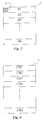
- Fig. 1 illustrates a first example decompression method for displaying a compressed image., and
- Fig. 2 illustrates a second example decompression method for displaying a compressed image.
- Fig. 1 illustrates a
compressed image memory 1 that holds a compressed image which is decompressed by adecompression apparatus 2 in a pipeline fashion with the output being forwarded for display on adisplay device 3. Often the display device has certain display requirements, such as, for example, each pixel of a given line having to be forwarded to thedisplay device 3 within a minimum time period for the display to function properly. For example, such is the case in rasterised displays. - If the decompression of a particular portion of the compressed image takes longer than the maximum time period for the forwarding to the
display device 3, then the compressed image will not be able to be displayed according to the method used in Fig. 1 as it will not be decompressed in time. In adisplay device 3 which requires synchronous input of uncompressed data it is necessary to maintain a consistent output data rate from the decompression process. It has been found that if the volume of compressed data is too large, then it is not possible to successfully decompress all the data at the data rate required for real time operation. Thus, the synchronous nature of the system cannot be maintained and the image cannot be successfully displayed. - Referring now to Fig. 2 there is shown a second example decompression method for displaying a compressed image. This method uses a batch arrangement designed to overcome the problems of the first method by decompressing, using a
decompression apparatus 5, a compressed image stored in a compressed image memory 4, and storing the decompressed image in a decompressed image store 6, which can then be forwarded to adisplay device 7 within the time requirements. However, this method fails to use the advantages of a compressed frame store as the entire image must be decompressed first and a large storage means is required to store the decompressed image before it is forwarded to thedisplay device 7. The need for such a large storage means often results in an undesirable and significant increase in expense of a corresponding computer graphics system using such an arrangement. - It is an object of the present invention to provide a means for decompressing a compressed image wherein the compressed image will always be decompressed within the real time requirements for the display on a display device.
- In accordance with a first aspect of the present invention, there is provided a method for the real-time display of a compressed image, the method comprising the steps of:
- (a) dividing the image into a plurality of bands,
- (b) compressing each of said bands using a first compression factor,
- (c) determining those invalid bands that cannot be decompressed within a first predetermined time and
- In accordance with a second aspect of the present invention, there is provided a method for the real-time display of a compressed image, the method comprising the steps of:
- (a) dividing the image into a plurality of bands,
- (b) compressing each of said bands using a first compression factor,
- (c) determining those invalid bands that cannot be decompressed within a first predetermined time and
- Preferably said filtering includes convolution of an invalid band with a predetermined convolution matrix.
- Preferably, said first predetermined number is chosen to be a proportion of the total number of bands in the image.
- A preferred embodiment of the present invention will now be described with reference to the remaining drawings in which:
- Fig. 3 illustrates an image made up of a number of bands.
- Fig. 4 illustrates the same image as FIG. 3 made up of compressed bands.
- Fig. 5 illustrates a 3x3 convolution matix used in the preferred embodiment.
- Fig. 6 illustrates an example decompressed band., and Figs. 7 to 10 are flowcharts which illustrate the method used in the preferred embodiment.
- The preferred method of compression of the image is the compression method as devised by the CCITT/ISO Joint Photographic Expert's Group (JPEG) based on the Discrete Cosine Transform and Huffman encoding processes and published in ISO/IEC JTC1/SC2/WG8 JPEG Technical Specification Rev 5 January 16, 1990.
- One implementation of a JPEG processor system has been implemented in silicon by C-Cube Microsystems as the CL550B device. The JPEG method allows the size of the compressed data relative to the uncompressed data to be selected (the compression ratio) and implementations of the JPEG algorithm such as the CL550B require a finite time to decompress a compressed image that has been compressed using the JPEG method.
- Referring now to Fig. 3 and Fig. 4 there is shown an input image 8 (Fig. 3) and its corresponding compressed image 9 (Fig. 4). For the purposes of the preferred embodiment the JPEG compressed
image 9 is organized in bands CB1, CB2, CB3... CBn, corresponding to fixed size image bands B1, B2, B3,... Bn in theinput image 8. The bands can, for example, contain eightscanlines 13 of image data as in the standard JPEG algorithm and a compressed image is comprised of a large number of compressed bands. - The situation arises that some of these bands may not successfully decompress at the synchronous rate required.
- Firstly a determination of those bands of a current image which are bad must be made. A band is considered "bad" if the time taken for it to be decompressed is greater than some predetermined time, that time being the maximum time required to get a band ready to send to a display device, such as a colour printer or video display.
- Preferably, if a band has been previously decompressed, the time required to decompress the band is stored with the band itself or in a separate table of all the band decompression times for a current image. If however, there is no timing information available for some or all bands, a test-print operation can be performed in order to determine the band decompression timings.
- If the number of bad bands requiring fixing is relatively low, for example less then say 5%, each bad band can be altered so that its decompression time is less than the predetermined time. One method of reducing the decompression time without substantially altering the original bad band is to reduce the amount of high frequency content in the bad band data. This can be achieved by blurring the luminance information, thereby improving the compressiblity of the current image. This can be done using a pixel averaging technique such as convolution over a group of pixels.
- As the JPEG compressed bad band data cannot be manipulated directly, it is necessary to decompress the JPEG bad band data, perform the convolution operation, and then recompress the data. The overall effect of this is blurring of the image in the bad bands. In the preferred embodiment, image data has the high frequency content of its luminance component reduced by pixel averaging over a certain area.
- Referring now to Fig. 5 there is shown a 3x3 convolution matrix 10 used in the preferred embodiment. The convolution matrix 10 consists of a current pixel position containing the value eight (8) and neighbouring pixel elements containing the value one (1).
- Referring now to Fig. 6 there is shown an example of a
decompressed band 11. When the convolution matrix 10 of Fig. 5 is applied to thedecompressed band 11, eachpixel 12 is averaged by multiplying itself by 8 and adding all its neighbours to the result before dividing the new result by 16 and storing it back in the current decompressed band. This particular convolution process has been designed to operate highly efficiently on a binary based digital processor. - If a substantial number of the bands of a current image are bad bands (say greater than 5%), then the entire image can be decompressed and recompressed at a higher compression ratio, which results in a lowering of the quality of the overall image, but an advantageous decrease in decompression time. The decision to recompress the entire image can be made to coincide with situations where the full recompression process will take less time than the blurring of a small number of bad bands in the input image. A higher compression ratio results in a decrease in the decompression time for each given band of the image, thereby reducing the likelihood of the occurrence of bad bands.
- Once the image has been recompressed, the process of location of bad bands or further recompression can be applied repeatedly to the current image until a final compressed image is obtained which meets those real-time printing requirements that may be required.
- It should be noted that the above process of blurring and recompression are destructive operations in that the image is left permanently altered after a printing or display operation that has had to alter the image. Hence, the saving of the current image (or rendering onto it) after such a print will be saving (or rendering onto) an altered image.
- Appendix A shows a pseudo code implementation of the recompression technique of the preferred embodiment for implementation on a computer system. The method disclosed can be implemented on any computer system configured with a display device having certain minimum synchronous display rate requirements as elucidated above.
- Referring now to Figs. 7 to 10, there is shown flowcharts of the pseudo-code of Appendix A.
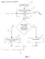
- Fig. 7 shows the overall main program "Ensure Current Image Printable". After initialization of
variables 20, a procedure GetMaximum Decompress Time 21 is called to determine the number of "Bad Bands" which cannot be decompressed in time. If the number of bad bands exceeds apredetermined number 22 the entire image is recompressed 23 at a higher compression ratio. Otherwise individual bad bands are blurred 24 to reduce their compression time. The program then enters areturn loop 25 to again determine if there are any remaining bad bands. - Referring now to Fig. 8, there is shown the procedure Get
Maximum Decompress Time 21 of Fig. 7 in more detail. This procedure first performs atest print 26 for all bands for which decompression timings are not available and then, for all bands in theimage 27, if the decompression time of the band exceeds a threshold, the number of bad bands (initially set to zero) is incremented. - Referring now to Fig. 9, there is shown the procedure
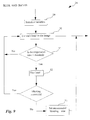
Blur Bad Bands 24 of Fig. 7. After initialization, of thevariables 29, each band in theimage 30 is checked 31 to determine if it's decompression time exceeds a predetermined threshold. If this is the case then the band is blurred. If the blurring is unsuccessful, the blur band procedure sets unsuccessful blurring to true (thereby causing the image to be recompressed), and exits. - Referring now to Fig.10, there is shown the
procedure Blur Band 32 of Fig. 9 in more detail. The blurring of a band involves the decompression of theband 34, it's convolution of the decompressed band with a convolution matrix previously described 35, and it'srecompression 36. - The foregoing describes only one embodiment of the present invention, and modifications, obvious to those skilled in the art, can be made thereto without departing from the scope of the present invention.


if the number of invalid bands is less than a first predetermined number, then filtering each band so that its decompression time is less than said first predetermined time, otherwise
if the number of invalid bands is greater than or equal to said first predetermined number, recompressing the whole image with a second compression factor such that each band can be decompressed in a shorter time interval less than said first predetermined time.
if the number of invalid bands is less than a first predetermined number, then filtering each band so that its decompression time is less than said first predetermined time, otherwise
if the number of invalid bands is greater than or equal to said first predetermined number, recompressing the whole image with a second compression factor such that each band can be decompressed in a shorter time interval and applying step (c) to said recompressed image.
Claims (11)
if the number of invalid bands is greater than or equal to said first predetermined number, recompressing the whole image with a second compression factor such that each band can be decompressed in a shorter time interval less than said first predetermined time.
if the number of invalid bands is greater than or equal to said first predetermined number, recompressing the whole image with a second compression factor such that each band can be decompressed in a shorter time interval and applying step (c) to said recompressed image.
means for dividing the image into a plurality of bands (B1,B2..Bn);
means for compressing each of said bands using a first compression factor (CB1,CB2..CBn); and
means for determining as invalid bands which cannot be decompressed within a predetermined time and
if the number of invalid bands is less than a first predetermined number, then filtering each band so that its decompression time is less than said first predetermined time, otherwise
if the number of invalid bands is greater than or equal to said first predetermined number, recompressing the whole image with a second compression factor such that each band can be decompressed in a shorter time interval less than said first predetermined time.
means for dividing the image into a plurality of bands (B1,B2..Bn);
means for compressing each of said bands using a first compression factor (CB1,CB2..CBn); and
means for determining as invalid bands which cannot be decompressed within a predetermined time and
if the number of invalid bands is less than a first predetermined number, then filtering each band so that its decompression time is less than said first predetermined time, otherwise
if the number of invalid bands is greater than or equal to said first predetermined number, recompressing the whole image with a second compression factor such that each band can be decompressed in a shorter time interval and applying step (c) to said recompressed image.
means for dividing the image into a plurality of bands (B1,B2..Bn);
means for compressing each of said bands using a first compression factor (CB1,CB2..CBn);
means for determining which bands cannot be decompressed within a first predetermined time; and
means for recompressing the whole image with a second compression factor such that each band can be decompressed in a time interval less than said first predetermined time in accordance with the result of said determining means.
Applications Claiming Priority (3)
| Application Number | Priority Date | Filing Date | Title |
|---|---|---|---|
| AU6834/93 | 1993-01-15 | ||
| AUPL683493 | 1993-01-15 | ||
| AU683493 | 1993-01-15 |
Publications (3)
| Publication Number | Publication Date |
|---|---|
| EP0609985A2 true EP0609985A2 (en) | 1994-08-10 |
| EP0609985A3 EP0609985A3 (en) | 1995-02-15 |
| EP0609985B1 EP0609985B1 (en) | 2002-06-05 |
Family
ID=3776658
Family Applications (1)
| Application Number | Title | Priority Date | Filing Date |
|---|---|---|---|
| EP94300255A Expired - Lifetime EP0609985B1 (en) | 1993-01-15 | 1994-01-14 | Compression factor adjustment to facilitate image display |
Country Status (4)
| Country | Link |
|---|---|
| US (1) | US5768424A (en) |
| EP (1) | EP0609985B1 (en) |
| JP (1) | JPH0738891A (en) |
| DE (1) | DE69430712D1 (en) |
Cited By (2)
| Publication number | Priority date | Publication date | Assignee | Title |
|---|---|---|---|---|
| EP0712095A3 (en) * | 1994-10-28 | 1996-10-30 | Seiko Epson Corp | Method and apparatus for image data compression |
| WO1998013787A1 (en) * | 1996-09-24 | 1998-04-02 | Colorage, Inc. | Adaptive block image compression |
Families Citing this family (9)
| Publication number | Priority date | Publication date | Assignee | Title |
|---|---|---|---|---|
| JPH11112722A (en) | 1997-09-30 | 1999-04-23 | Minolta Co Ltd | Image forming device and image forming system |
| AU2001261897B2 (en) * | 2000-05-29 | 2004-12-16 | Canon Kabushiki Kaisha | A method for enabling file format compatibility |
| AUPR192700A0 (en) | 2000-12-06 | 2001-01-04 | Canon Kabushiki Kaisha | Storing coding image data in storage of fixed memory size |
| AU2003900531A0 (en) * | 2003-01-30 | 2003-02-20 | Canon Kabushiki Kaisha | Compression into a fixed buffer |
| JP2004297772A (en) * | 2003-03-12 | 2004-10-21 | Ricoh Co Ltd | Image processing system, image forming apparatus, image processing method, program and recording medium |
| US7305490B2 (en) * | 2003-07-29 | 2007-12-04 | Hewlett-Packard Development Company, L.P. | Preparing electronic data for transmission |
| US7893949B2 (en) * | 2005-07-26 | 2011-02-22 | Brother Kogyo Kabushiki Kaisha | Image display apparatus |
| AU2007237313A1 (en) * | 2007-12-03 | 2009-06-18 | Canon Kabushiki Kaisha | Improvement for error correction in distributed vdeo coding |
| JP6447531B2 (en) * | 2016-01-29 | 2019-01-09 | オムロン株式会社 | Signal processing apparatus, signal processing apparatus control method, control program, and recording medium |
Citations (4)
| Publication number | Priority date | Publication date | Assignee | Title |
|---|---|---|---|---|
| US4394774A (en) * | 1978-12-15 | 1983-07-19 | Compression Labs, Inc. | Digital video compression system and methods utilizing scene adaptive coding with rate buffer feedback |
| EP0382892A1 (en) * | 1989-02-14 | 1990-08-22 | Mitsubishi Denki Kabushiki Kaisha | Picture signal encoding and decoding apparatus |
| EP0417943A2 (en) * | 1989-09-14 | 1991-03-20 | Kabushiki Kaisha Toshiba | Cell transfer apparatus and method using a variable rate codec |
| EP0487282A2 (en) * | 1990-11-19 | 1992-05-27 | Canon Kabushiki Kaisha | Image processing apparatus |
Family Cites Families (8)
| Publication number | Priority date | Publication date | Assignee | Title |
|---|---|---|---|---|
| US5122873A (en) * | 1987-10-05 | 1992-06-16 | Intel Corporation | Method and apparatus for selectively encoding and decoding a digital motion video signal at multiple resolution levels |
| US5051840A (en) * | 1988-12-14 | 1991-09-24 | Fuji Photo Film Co., Ltd. | Device for coding a picture signal by compression |
| GB8900368D0 (en) * | 1989-01-09 | 1989-03-08 | Crosfield Electronics Ltd | Bit map modification |
| JPH02305182A (en) * | 1989-05-19 | 1990-12-18 | Fuji Photo Film Co Ltd | Picture signal compressing and encoding device |
| US5121216A (en) * | 1989-07-19 | 1992-06-09 | Bell Communications Research | Adaptive transform coding of still images |
| JP2881886B2 (en) * | 1989-12-30 | 1999-04-12 | ソニー株式会社 | Video signal encoding method and apparatus therefor |
| US5228098A (en) * | 1991-06-14 | 1993-07-13 | Tektronix, Inc. | Adaptive spatio-temporal compression/decompression of video image signals |
| US5287420A (en) * | 1992-04-08 | 1994-02-15 | Supermac Technology | Method for image compression on a personal computer |
-
1994
- 1994-01-12 US US08/180,321 patent/US5768424A/en not_active Expired - Lifetime
- 1994-01-14 EP EP94300255A patent/EP0609985B1/en not_active Expired - Lifetime
- 1994-01-14 DE DE69430712T patent/DE69430712D1/en not_active Expired - Lifetime
- 1994-01-14 JP JP6002654A patent/JPH0738891A/en not_active Withdrawn
Patent Citations (4)
| Publication number | Priority date | Publication date | Assignee | Title |
|---|---|---|---|---|
| US4394774A (en) * | 1978-12-15 | 1983-07-19 | Compression Labs, Inc. | Digital video compression system and methods utilizing scene adaptive coding with rate buffer feedback |
| EP0382892A1 (en) * | 1989-02-14 | 1990-08-22 | Mitsubishi Denki Kabushiki Kaisha | Picture signal encoding and decoding apparatus |
| EP0417943A2 (en) * | 1989-09-14 | 1991-03-20 | Kabushiki Kaisha Toshiba | Cell transfer apparatus and method using a variable rate codec |
| EP0487282A2 (en) * | 1990-11-19 | 1992-05-27 | Canon Kabushiki Kaisha | Image processing apparatus |
Cited By (3)
| Publication number | Priority date | Publication date | Assignee | Title |
|---|---|---|---|---|
| EP0712095A3 (en) * | 1994-10-28 | 1996-10-30 | Seiko Epson Corp | Method and apparatus for image data compression |
| US5852710A (en) * | 1994-10-28 | 1998-12-22 | Seiko Epson Corporation | Apparatus and method for storing image data into memory |
| WO1998013787A1 (en) * | 1996-09-24 | 1998-04-02 | Colorage, Inc. | Adaptive block image compression |
Also Published As
| Publication number | Publication date |
|---|---|
| JPH0738891A (en) | 1995-02-07 |
| DE69430712D1 (en) | 2002-07-11 |
| US5768424A (en) | 1998-06-16 |
| EP0609985B1 (en) | 2002-06-05 |
| EP0609985A3 (en) | 1995-02-15 |
Similar Documents
| Publication | Publication Date | Title |
|---|---|---|
| US6192155B1 (en) | Systems and methods for reducing boundary artifacts in hybrid compression | |
| US5287420A (en) | Method for image compression on a personal computer | |
| JP2922680B2 (en) | Compressed image storage method for high-resolution computer graphics | |
| US6529633B1 (en) | Parallel difference coding method for lossless compression and real time decompression | |
| EP1581008A2 (en) | parallel processing of an image and its corresponding thumbnail | |
| JPH08289324A (en) | Color image transmitting device | |
| US6442302B2 (en) | Rotated read-out of JPEG compressed images | |
| EP0609985A2 (en) | Compression factor adjustment to facilitate image display | |
| KR100834439B1 (en) | Compression and decompression device of graphic data and therefor method | |
| US6898310B1 (en) | Image signal processing method, image signal processing system, storage medium, and image sensing apparatus | |
| EP0781493B1 (en) | Packed yuv9 format for interleaved storage and efficient processing of digital video data | |
| US6353682B2 (en) | Rotated read-out of JPEG compressed images | |
| US6721455B1 (en) | Method and apparatus for icon compression and decompression | |
| US7245781B2 (en) | Applying a tone scale function to a digital image | |
| US6829385B2 (en) | Apparatus and method for processing images, and a computer-readable medium | |
| US5862412A (en) | Apparatus for converting document data into bit map data and compressing display image formed by combining the bit map data and image data | |
| AU672649B2 (en) | Compression factor adjustment to facilitate image display | |
| JP4329429B2 (en) | Image transfer apparatus, image transfer method, and image transfer program | |
| US6069980A (en) | Adaptive character image generation and synthesis | |
| US5757975A (en) | Artifact reduction for large dynamic range input data in JPEG compression | |
| JP3023215B2 (en) | Image processing device | |
| JPH07118002B2 (en) | Image processing device | |
| US20050018910A1 (en) | Method and apparatus for reducing the bandwidth required to transmit image data | |
| US6301384B1 (en) | Low pass blurring image filter for filtering only green | |
| JPH05261982A (en) | Printing device |
Legal Events
| Date | Code | Title | Description |
|---|---|---|---|
| PUAI | Public reference made under article 153(3) epc to a published international application that has entered the european phase |
Free format text: ORIGINAL CODE: 0009012 |
|
| AK | Designated contracting states |
Kind code of ref document: A2 Designated state(s): DE FR GB IT |
|
| PUAL | Search report despatched |
Free format text: ORIGINAL CODE: 0009013 |
|
| AK | Designated contracting states |
Kind code of ref document: A3 Designated state(s): DE FR GB IT |
|
| 17P | Request for examination filed |
Effective date: 19950629 |
|
| 17Q | First examination report despatched |
Effective date: 19980316 |
|
| RIC1 | Information provided on ipc code assigned before grant |
Free format text: 6G 06T 9/00 A |
|
| RAP1 | Party data changed (applicant data changed or rights of an application transferred) |
Owner name: CANON KABUSHIKI KAISHA |
|
| GRAG | Despatch of communication of intention to grant |
Free format text: ORIGINAL CODE: EPIDOS AGRA |
|
| GRAG | Despatch of communication of intention to grant |
Free format text: ORIGINAL CODE: EPIDOS AGRA |
|
| GRAH | Despatch of communication of intention to grant a patent |
Free format text: ORIGINAL CODE: EPIDOS IGRA |
|
| GRAH | Despatch of communication of intention to grant a patent |
Free format text: ORIGINAL CODE: EPIDOS IGRA |
|
| GRAA | (expected) grant |
Free format text: ORIGINAL CODE: 0009210 |
|
| AK | Designated contracting states |
Kind code of ref document: B1 Designated state(s): DE FR GB IT |
|
| PG25 | Lapsed in a contracting state [announced via postgrant information from national office to epo] |
Ref country code: IT Free format text: LAPSE BECAUSE OF FAILURE TO SUBMIT A TRANSLATION OF THE DESCRIPTION OR TO PAY THE FEE WITHIN THE PRE;WARNING: LAPSES OF ITALIAN PATENTS WITH EFFECTIVE DATE BEFORE 2007 MAY HAVE OCCURRED AT ANY TIME BEFORE 2007. THE CORRECT EFFECTIVE DATE MAY BE DIFFERENT FROM THE ONE RECORDED.SCRIBED TIME-LIMIT Effective date: 20020605 Ref country code: FR Free format text: LAPSE BECAUSE OF FAILURE TO SUBMIT A TRANSLATION OF THE DESCRIPTION OR TO PAY THE FEE WITHIN THE PRESCRIBED TIME-LIMIT Effective date: 20020605 |
|
| REG | Reference to a national code |
Ref country code: GB Ref legal event code: FG4D |
|
| REF | Corresponds to: |
Ref document number: 69430712 Country of ref document: DE Date of ref document: 20020711 |
|
| PG25 | Lapsed in a contracting state [announced via postgrant information from national office to epo] |
Ref country code: DE Free format text: LAPSE BECAUSE OF FAILURE TO SUBMIT A TRANSLATION OF THE DESCRIPTION OR TO PAY THE FEE WITHIN THE PRESCRIBED TIME-LIMIT Effective date: 20020906 |
|
| EN | Fr: translation not filed | ||
| PLBE | No opposition filed within time limit |
Free format text: ORIGINAL CODE: 0009261 |
|
| STAA | Information on the status of an ep patent application or granted ep patent |
Free format text: STATUS: NO OPPOSITION FILED WITHIN TIME LIMIT |
|
| 26N | No opposition filed |
Effective date: 20030306 |
|
| PGFP | Annual fee paid to national office [announced via postgrant information from national office to epo] |
Ref country code: GB Payment date: 20130123 Year of fee payment: 20 |
|
| REG | Reference to a national code |
Ref country code: GB Ref legal event code: PE20 Expiry date: 20140113 |
|
| PG25 | Lapsed in a contracting state [announced via postgrant information from national office to epo] |
Ref country code: GB Free format text: LAPSE BECAUSE OF EXPIRATION OF PROTECTION Effective date: 20140113 |