EP0612542A1 - Platform reproducing periodical movements in three axes, with a preferential direction - Google Patents
Platform reproducing periodical movements in three axes, with a preferential direction Download PDFInfo
- Publication number
- EP0612542A1 EP0612542A1 EP94400405A EP94400405A EP0612542A1 EP 0612542 A1 EP0612542 A1 EP 0612542A1 EP 94400405 A EP94400405 A EP 94400405A EP 94400405 A EP94400405 A EP 94400405A EP 0612542 A1 EP0612542 A1 EP 0612542A1
- Authority
- EP
- European Patent Office
- Prior art keywords
- crank
- platform
- platform according
- base
- connecting rod
- Prior art date
- Legal status (The legal status is an assumption and is not a legal conclusion. Google has not performed a legal analysis and makes no representation as to the accuracy of the status listed.)
- Granted
Links
Images

Classifications
-
- A—HUMAN NECESSITIES
- A63—SPORTS; GAMES; AMUSEMENTS
- A63B—APPARATUS FOR PHYSICAL TRAINING, GYMNASTICS, SWIMMING, CLIMBING, OR FENCING; BALL GAMES; TRAINING EQUIPMENT
- A63B69/00—Training appliances or apparatus for special sports
- A63B69/04—Training appliances or apparatus for special sports simulating the movement of horses
-
- A—HUMAN NECESSITIES
- A63—SPORTS; GAMES; AMUSEMENTS
- A63G—MERRY-GO-ROUNDS; SWINGS; ROCKING-HORSES; CHUTES; SWITCHBACKS; SIMILAR DEVICES FOR PUBLIC AMUSEMENT
- A63G19/00—Toy animals for riding
- A63G19/20—Toy animals for riding motor-driven
Definitions
- Numerous mobiles such as planes, boats or even horses whose movement takes place essentially in a preferred direction are, moreover, driven by periodic movements along the three axes: longitudinal, transverse and vertical.
- the object of the present invention is to produce a mobile platform reproducing periodic movements along the three axes with a preferred direction, this platform being set in motion by extremely simple mechanical means and therefore being inexpensive to manufacture.
- the invention provides a mobile platform intended to reproduce periodic movements along the three axes (longitudinal, transverse, vertical) with a preferred direction, said platform being carried by a base on the one hand, at one end (called “rear”) by means of at least one foot coupled to a crank and on the other hand, at the other end (called “front”) by connecting rods hinged to said base, characterized in that said crank is carried by a support connected to the base by a foot which can be moved laterally so that the crank is located either in a vertical plane comprising the preferred direction, or in an oblique plane on one side or the other with respect to said vertical plane, and in that the two front feet are each articulated on a substantially vertical connecting rod, each connecting rod being articulated directly or indirectly at its lower end on the base.
- the machine is constituted by a base 1 which is preferably rectangular.
- This base supports a platform 2 by means of three feet 3, 4 and 5.
- the foot 3 which by convention will be called the rear foot, is connected by a hinge 6 to a crank 7 which can be constituted by a simple arm, as indicated in dotted lines, or by a disc, as shown in solid lines .
- This crank 7 is mounted for rotation on an axis 8 carried by a support 9 resting on the base 1.
- the foot 9a of the support 9 can be moved in one direction or the other along the line 10.
- the support 9 and the crank 7 are arranged in a vertical plane which includes the rear leg 3.
- the support 9 and the crank 7 are placed in an oblique plane, bent to the right or left.
- this position corresponds to the preferred direction XX of the movement of the platform 2.
- the means by which the foot 9a is placed in the desired position are not described because they are not part of the invention and are within the scope of the skilled person. They can be constituted by a slide with screws blocking, by a rack, by an endless screw or by a jack.
- the modification of the position of the foot 9a of the support 9 can be carried out as an adjustment before the machine is started up or can be made during the operation by means of a remote control.
- the shaft 8 is provided with a pulley 11 connected by a belt 12 to the pulley 13 of a motor 14 which is of variable speed and the direction of which can be reversed.
- This motor 14 is provided with control means which make it possible to rotate it in one direction or the other, and to vary its speed of rotation, that is to say the number of revolutions per minute. Means can also be made available for varying the speed cyclically during the execution of each turn.
- One of the front feet, the left foot 4 in the example shown, is articulated to a connecting rod 15, substantially vertical, by means of a joint 16 located at the upper part of the connecting rod 15.
- the connecting rod is directly articulated at its lower part on the base by an articulation 17 linked to a support 18 which is fixed to the base 1.
- the other front foot, the right foot 5 in the example shown, is articulated by an articulation 19 to a connecting rod 20, substantially vertical.
- the connecting rod 19 is directly articulated on the base while being pivotally mounted on an axis 21.
- This axis 21 is horizontal and perpendicular or practically perpendicular to the preferred direction XX.
- the connecting rod 20 is triangulated by means of a horizontal arm 22 and a stay 23.
- the position of the foot 5 on the platform 2 can be changed in the direction indicated by the line 24 in one direction or the other as indicated by the double arrow f2.
- the means allowing these displacements are analogous to those mentioned about the movement of the foot 9a of the support 9.
- the platform is rectangular and has a seat 25 which is located on the median longitudinal axis XX of the platform 2.
- This seat 25 can be moved in one direction or the other, in the direction XX as indicated by the double arrow f3. Again, the means for these movements are similar to those mentioned for the support 9 and the foot 5.
- the crank is in a vertical plane and if the line connecting the feet 5 and 4 is perpendicular to the direction XX, the foot 3 is animated by a rotary movement in a vertical plane and the feet 4 and 5 each describe an arc de-circle in a vertical plane.
- the seat 25 is therefore driven in a forward and backward movement in the direction XX, as well as a pitching movement (up and down). It is understood that, the more the seat 25 is at the front, the greater the displacement due to pitching, while the more the seat is at the rear, the less this movement.
- the line which connects the feet 4 and 5 is no longer perpendicular to the direction XX and to the various movements previously described will overlap a movement of roll.
- the disc 7 can be replaced by an arm of variable length.
- the joint 6 in a window 26 formed in the disc 7 asymmetrically, this joint being able to slide freely in said window and coming to abut against one or the other of the ends of this window 26 according to the direction of rotation of the disc 7.
- the invention makes it possible, among other things, to simulate the gaits of a horse (tread, trot, gallop and jump).
- the invention is not limited to this particular case and the seat 25 can be arranged in the opposite direction and in this case the rear leg becomes front and vice versa.
- joints 6, 16, 17 and 19 are capable of ensuring movements in all directions. They can therefore be formed either by pins mounted to play in their bearings, or by rubber pads like silentbloc, or by ball joints or cardan joints.
- the foot 3 that is to say to have two parallel feet which are connected to the same crank or to a double crank.
- Such an arrangement then eliminates any possibility of rolling movement (longitudinal axis) but makes the connection between the platform and the crank more solid. Still with the aim of making the machine more solid, the two connecting rods 15 and 20 can be braced.
- the connecting rods 15 and 20 on which the front legs 4 and 5 of the platform are articulated are indirectly articulated on the base, being carried by a spindle 30 in two bearings 31.
- the shaft 30 is bent so that the lower ends of said connecting rods are driven by a movement of amplitude R.
- the shaft 31 is rotated by the motor 14 or by a second motor, via a pulley 33 which it carries.
- This embodiment makes it possible to perform pitch movements independently of the position of the support 9 of the rear foot.
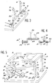
- the variant embodiment of FIG. 4 makes it possible to carry out roll movements at the same time as pitch movements independently of the position of the support 9, of the rear foot, by phase differentiation.
- the shaft carrying the lower ends of the connecting rods 15 and 20 is such that it has a first portion 35 carrying the connecting rod 20 describing a cylinder of radius R1, and a second portion 34 carrying the connecting rod 15 describing a cylinder of radius R2, different from R1.
- FIG. 5 also shows an alternative embodiment of the mobile platform according to the invention.
- the rear foot 3 is articulated on the platform 2 by means of a ball joint 35, while the ball joint 6 located in the variant according to FIG. 1 between the foot 3 and the crank 7 is replaced by a simple articulation.
- a second crank 37 which may, as previously, be constituted by a simple arm or by a disc is arranged around the axis 8.
- a connecting rod 36 is disposed between this crank 37 and the ball joint 19 connecting the front leg 5 to the connecting rod 20, so as to impart to the connecting rod 20 oscillating movements.
Abstract
Description
De nombreux mobiles tels que des avions, des bateaux ou encore des chevaux dont le déplacement se fait essentiellement dans une direction privilégiée sont, en outre, animés de mouvements périodiques selon les trois axes: longitudinal, transversal et vertical.Numerous mobiles such as planes, boats or even horses whose movement takes place essentially in a preferred direction are, moreover, driven by periodic movements along the three axes: longitudinal, transverse and vertical.
Il est connu par le document EP 0 407 158 de disposer une plate-forme mobile sur d'une part un pied arrière double articulé à rotation sur un socle et sous la plate-forme, d'autre part sur deux pieds avant articulés à rotation sur le socle et sous la plate-forme et présentant une articulation en leur milieu. L'articulation placée sous la plate-forme de l'un des pieds avant est déplacée par une première bielle et une première manivelle entraînée en rotation par un moteur. L'articulation placée au milieu de l'autre pied avant est déplacée par une deuxième bielle et une deuxième manivelle entraînée elle aussi en rotation par le moteur. Cet ensemble peut imprimer à la plate-forme des mouvements limités au plan vertical médian, c'est-à-dire des mouvements de tangage, à l'exclusion de mouvements de roulis et de mouvements de lacet.It is known from document EP 0 407 158 to have a mobile platform on the one hand a double rear foot articulated in rotation on a base and under the platform, on the other hand on two front feet articulated in rotation on the base and under the platform and having a hinge in the middle. The articulation placed under the platform of one of the front legs is moved by a first connecting rod and a first crank driven in rotation by a motor. The articulation placed in the middle of the other front foot is moved by a second connecting rod and a second crank also driven in rotation by the motor. This assembly can print on the platform movements limited to the median vertical plane, that is to say pitch movements, excluding roll movements and yaw movements.
Il est également connu de réaliser des simulateurs, par exemple avec des plates-formes à six degrés de liberté qui permettent de reproduire de tels mouvements de façon satisfaisante. Cependant de tels simulateurs sont des machines onéreuses.It is also known to produce simulators, for example with platforms with six degrees of freedom which make it possible to reproduce such movements satisfactorily. However, such simulators are expensive machines.
La présente invention a pour objet de réaliser une plate-forme mobile reproduisant des mouvements périodiques selon les trois axes avec une direction privilégiée, cette plate-forme étant mise en mouvement par des moyens mécaniques extrêmement simples et étant donc de fabrication peu coûteuse.The object of the present invention is to produce a mobile platform reproducing periodic movements along the three axes with a preferred direction, this platform being set in motion by extremely simple mechanical means and therefore being inexpensive to manufacture.
L'invention propose une plate-forme mobile destinée à reproduire des mouvements périodiques selon les trois axes (longitudinal, transversal, vertical) avec une direction privilégiée, ladite plate-forme étant portée par un socle d'une part, à une extrémité (dite "arrière") par l'intermédiaire d'au moins un pied attelé à une manivelle et d'autre part, à l'autre extrémité (dite "avant") par des bielles articulées audit socle, caractérisée par le fait que ladite manivelle est portée par un support relié au socle par un pied pouvant être déplacé latéralement de façon telle que la manivelle se trouve soit dans un plan vertical comprenant la direction privilégiée, soit dans un plan oblique d'un côté ou de l'autre par rapport audit plan vertical, et en ce que les deux pieds avant sont articulés chacun sur une bielle sensiblement verticale, chaque bielle étant articulée directement ou indirectement à son extrémité inférieure sur le socle.The invention provides a mobile platform intended to reproduce periodic movements along the three axes (longitudinal, transverse, vertical) with a preferred direction, said platform being carried by a base on the one hand, at one end (called "rear") by means of at least one foot coupled to a crank and on the other hand, at the other end (called "front") by connecting rods hinged to said base, characterized in that said crank is carried by a support connected to the base by a foot which can be moved laterally so that the crank is located either in a vertical plane comprising the preferred direction, or in an oblique plane on one side or the other with respect to said vertical plane, and in that the two front feet are each articulated on a substantially vertical connecting rod, each connecting rod being articulated directly or indirectly at its lower end on the base.
Par commodité de langage et pour faciliter la compréhension de la description on appellera "arrière" le pied qui est attelé à la manivelle et "avant" les deux autres, mais il doit être bien entendu que l'invention n'est pas limitée à ce sens, ce qui est appelé avant pouvant être arrière et vice-versa.For convenience of language and to facilitate understanding of the description, the foot which is coupled to the crank will be called "rear" and the other two "front", but it should be understood that the invention is not limited to this. meaning, what is called front can be back and vice versa.
L'invention peut comporter également les caractéristiques suivantes :
- l'articulation sur le socle de l'une des deux bielles avant est constituée par un axe horizontal sensiblement perpendiculaire à la direction privilégiée,
- la position d'un des deux pieds avant par rapport à la plate-forme peut être modifiée à volonté,
- la plate-forme est munie d'un emplacement pour l'utilisateur dont la position peut être modifiée à volonté.
- le pied arrière peut être simple ou double,
- la manivelle à laquelle est attelé le pied arrière peut être un bras de longueur variable ou un disque,
- la manivelle du pied arrière est entraînée en rotation par un moteur à vitesse variable,
- la manivelle du pied arrière est constituée par un disque muni d'une fenêtre dans laquelle peut se déplacer le point d'articulation dudit pied,
- la vitesse de rotation du moteur est commandée par des moyens permettant de faire varier le nombre de tours par minute et en plus de faire varier cycliquement la vitesse pendant chaque tour,
- les pieds avant sont indirectement articulées sur le socle en étant portées par un arbre tourillonnant dans deux paliers, ledit arbre étant coudé afin que les extrémités inférieures desdites bielles soient animées d'un mouvement d'amplitude R, de façon à imprimer à la plate-forme des mouvements de tangage,
- l'arbre présente une première portion portant une bielle décrivant un cylindre de premier rayon et une seconde portion portant une bielle décrivant un cylindre de second rayon différent du premier, de façon à imprimer à la plate-forme des mouvements de roulis en même temps que des mouvements de tangage,
- le pied arrière est articulé sur la plate-forme au moyen d'une rotule et une seconde manivelle entraîne une bielle disposée entre cette manivelle et la rotule reliant le pied avant à la bielle articulée sur le socle, de façon à imprimer à ladite bielle des mouvements d'oscillation.
- the articulation on the base of one of the two front connecting rods is constituted by a horizontal axis substantially perpendicular to the preferred direction,
- the position of one of the two front feet relative to the platform can be changed at will,
- the platform is provided with a location for the user whose position can be changed at will.
- the rear foot can be single or double,
- the crank to which the rear foot is coupled may be an arm of variable length or a disc,
- the rear leg crank is rotated by a variable speed motor,
- the crank of the rear foot is constituted by a disc provided with a window in which the articulation point of said foot can move,
- the speed of rotation of the motor is controlled by means making it possible to vary the number of revolutions per minute and in addition to varying the speed cyclically during each revolution,
- the front feet are indirectly articulated on the base while being carried by a swiveling shaft in two bearings, said shaft being bent so that the lower ends of said connecting rods are given a movement of amplitude R, so as to print on the platform form of pitch movements,
- the shaft has a first portion carrying a connecting rod describing a cylinder of first radius and a second portion carrying a connecting rod describing a cylinder of second radius different from the first, so as to impart to the platform rolling movements at the same time as pitch movements,
- the rear foot is articulated on the platform by means of a ball joint and a second crank drives a connecting rod disposed between this crank and the ball joint connecting the front foot to the connecting rod articulated on the base, so as to print on said connecting rod oscillation movements.
L'invention sera mieux comprise grâce à la description qui va suivre donnée à titre d'exemple non limitatif en référence aux dessins annexés dans lesquels :
- la figure 1 est une vue schématique en perspective d'un mode de réalisation de l'invention,
- la figure 2 est une vue schématique d'une variante de réalisation du disque-manivelle de la figure 1,
- les figures 3 et 4 sont des vues partielles pour deux variantes de réalisation d'une articulation indirecte des pieds avant sur le socle,
- la figure 5 est une vue semblable à la figure 1 pour encore une variante de réalisation de la plate-forme selon l'invention.
- FIG. 1 is a schematic perspective view of an embodiment of the invention,
- FIG. 2 is a schematic view of an alternative embodiment of the crank disk of FIG. 1,
- FIGS. 3 and 4 are partial views for two alternative embodiments of an indirect articulation of the front feet on the base,
- Figure 5 is a view similar to Figure 1 for yet another alternative embodiment of the platform according to the invention.
En se reportant à la figure 1, on voit que la machine est constituée par un socle 1 qui est de préférence rectangulaire.Referring to Figure 1, we see that the machine is constituted by a
Ce socle supporte une plate-forme 2 au moyen de trois pieds 3, 4 et 5.This base supports a
Le pied 3, que par convention on appellera pied arrière, est relié par une articulation 6 à une manivelle 7 qui peut être constituée par un simple bras, comme cela est indiqué en pointillé, ou par un disque, comme cela est représenté en traits pleins. Cette manivelle 7 est montée à rotation sur un axe 8 porté par un support 9 reposant sur le socle 1.The
Comme cela est indiqué schématiquement par le trait interrompu 10 et la double flèche f₁, le pied 9a du support 9 peut être déplacé dans un sens ou dans l'autre le long de la ligne 10. En position médiane, le support 9 et la manivelle 7 sont disposés dans un plan vertical qui comprend le pied arrière 3. En déplaçant le pied 9a d'un côté ou de l'autre de cette position médiane, on met le support 9 et la manivelle 7 dans un plan oblique, penché à droite ou à gauche.As indicated schematically by the
Lorsque la manivelle 7 est dans un plan vertical, cette position correspond à la direction privilégiée XX du mouvement de la plate-forme 2.When the
Les moyens par lesquels le pied 9a est mis dans la position désirée ne sont pas décrits parce qu'ils ne font pas partie de l'invention et sont du domaine de l'homme du métier. Ils peuvent être constitués par une glissière avec des vis de blocage, par une crémaillère, par une vis sans fin ou par un vérin.The means by which the foot 9a is placed in the desired position are not described because they are not part of the invention and are within the scope of the skilled person. They can be constituted by a slide with screws blocking, by a rack, by an endless screw or by a jack.
La modification de la position du pied 9a du support 9 peut être opérée comme un réglage avant la mise en marche de la machine ou peut-être faite pendant la marche au moyen d'une télécommande.The modification of the position of the foot 9a of the
L'arbre 8 est muni d'une poulie 11 reliée par une courroie 12 à la poulie 13 d'un moteur 14 qui est à vitesse variable et dont on peut inverser le sens. Ce moteur 14 est muni de moyens de commande qui permettent de le faire tourner dans un sens ou dans l'autre, et de faire varier sa vitesse de rotation, c'est-à-dire le nombre de tours par minute. On peut également disposer des moyens permettant de faire varier cycliquement la vitesse pendant l'exécution de chaque tour.The
L'un des pieds avant, le pied gauche 4 dans l'exemple représenté, est articulé à une bielle 15, sensiblement verticale, au moyen d'une articulation 16 située à la partie supérieure de la bielle 15. Dans cette variante de réalisation, la bielle est directement articulée à sa partie inférieure sur le socle par une articulation 17 liée à un support 18 qui est fixé au socle 1.One of the front feet, the
L'autre pied avant, le pied droit 5 dans l'exemple représenté, est articulé par une articulation 19 à une bielle 20, sensiblement verticale. A sa partie inférieure, la bielle 19 est directement articulée sur le socle en étant montée à pivotement sur un axe 21. Cet axe 21 est horizontal et perpendiculaire ou pratiquement perpendiculaire à la direction privilégiée XX. Pour plus de solidité, la bielle 20 est triangulée au moyen d'un bras horizontal 22 et d'un étai 23.The other front foot, the
La position du pied 5 sur la plate-forme 2 peut être modifiée selon la direction indiquée par la ligne 24 dans un sens ou l'autre comme indiqué par la flèche double f₂. Les moyens permettant ces déplacements sont analogues à ceux mentionnés au sujet du déplacement du pied 9a du support 9.The position of the
Dans l'exemple représenté, la plate-forme est rectangulaire et comporte un siège 25 qui est situé sur l'axe longitudinal médian XX de la plate-forme 2. Ce siège 25 peut être déplacé dans un sens ou dans l'autre, dans la direction XX comme indiqué par la flèche double f₃. Là également, les moyens permettant ces déplacements sont analogues à ceux mentionnés pour le support 9 et le pied 5.In the example shown, the platform is rectangular and has a
Lorsque le moteur 14 est mis en action, il entraîne en rotation la manivelle 7.When the
Si la manivelle est dans un plan vertical et si la droite reliant les pieds 5 et 4 est perpendiculaire à la direction XX, le pied 3 est animé d'un mouvement rotatif dans un plan vertical et les pieds 4 et 5 décrivent chacun un arc-de-cercle dans un plan vertical. Le siège 25 est donc animé d'un mouvement d'avancée et de recul selon la direction XX, ainsi que d'un mouvement de tangage (montée et descente). On comprend que, plus le siège 25 est à l'avant plus le déplacement dû au tangage est important, tandis que plus le siège est à l'arrière plus ce mouvement est faible.If the crank is in a vertical plane and if the line connecting the
Si le pied 9a du support 9 est déplacé selon la flèche f₁ d'un côté ou de l'autre de sa position médiane (pour laquelle la manivelle 7 se déplace dans un plan vertical), au mouvement précédemment décrit va se superposer un mouvement latéral du pied 3 et donc un mouvement de lacet. Mais on aura toujours l'essentiel du mouvement qui se fait dans la direction XX, que l'on dénomme pour cette raison "direction privilégiée".If the foot 9a of the
Si le pied 5 est déplacé dans un sens ou dans l'autre le long de la ligne 24, la droite qui relie les pieds 4 et 5 n'est plus perpendiculaire à la direction XX et aux divers mouvements précédemment décrits va se superposer un mouvement de roulis.If the
On obtient donc outre un mouvement d'avancée et de recul dans une direction privilégiée une superposition de mouvements selon les trois axes de tangage, de roulis et de lacets dont on peut régler l'amplitude à volonté.We therefore obtain, in addition to a forward and backward movement in a preferred direction, a superposition of movements along the three axes of pitch, roll and laces, the amplitude of which can be adjusted as desired.
Afin de pouvoir régler l'amplitude du tangage divers moyens sont possibles, on peut remplacer le disque 7 par un bras de longueur variable. On peut aussi comme cela est représenté figure 2, disposer l'articulation 6 dans une fenêtre 26 ménagée dans le disque 7 de façon dissymétrique, cette articulation pouvant glisser librement dans ladite fenêtre et venant se mettre en butée contre l'une ou l'autre des extrémités de cette fenêtre 26 suivant le sens de rotation du disque 7.In order to be able to adjust the amplitude of the pitch various means are possible, the
La combinaison des mouvements ainsi décrits et la possibilité d'en faire varier l'amplitude et la fréquence permettent de simuler avec une approximation très satisfaisante, le déplacement de divers mobiles se déplaçant selon une direction d'avancement (direction privilégiée) tout en ayant des mouvements complémentaires selon les trois axes (longitudinal, transversal, vertical).The combination of the movements thus described and the possibility of varying their amplitude and frequency make it possible to simulate, with a very satisfactory approximation, the displacement of various mobiles moving in a direction of advance (preferred direction) while having complementary movements along the three axes (longitudinal, transverse, vertical).
L'invention permet, entre autres, de simuler les allures d'un cheval (pas, trot, galop et le saut). Cependant, l'invention n'est pas limitée à ce cas particulier et le siège 25 peut être disposé en sens inverse et dans ce cas le pied arrière devient avant et vice-versa.The invention makes it possible, among other things, to simulate the gaits of a horse (tread, trot, gallop and jump). However, the invention is not limited to this particular case and the
Les multiples moyens de réglage tels que :
- position du siège 25,
- inclinaison de la manivelle 7,
- longueur des manivelles 7, 37,
- position du pied 5,
- sens de rotation du moteur 14,
- vitesse de rotation du moteur 14,
- variation cyclique de la vitesse de rotation du moteur dans une révolution,
permettent de régler à volonté les différents paramètres des mouvements de la plate-forme et donc d'affiner la simulation des mouvements que l'on veut reproduire, en particulier ceux correspondant aux différentes allures d'un cheval.The multiple means of adjustment such as:
-
seat position 25, - tilt of the
crank 7, - length of
cranks - position of
foot 5, - direction of rotation of the
motor 14, -
motor rotation speed 14, - cyclic variation of the engine speed in one revolution,
allow to adjust at will the different parameters of the movements of the platform and therefore to refine the simulation of the movements that we want to reproduce, in particular those corresponding to the different gaits of a horse.
Ces mouvements multiples nécessitent que les articulations 6, 16, 17 et 19 soient susceptible d'assurer des mouvements dans tous les sens. Elles peuvent donc être constituées soit par des axes montés à jeu dans leurs paliers, soit par des coussinets en caoutchouc genre silentbloc, soit par des rotules ou des cardans.These multiple movements require that the
Selon une variante de réalisation de l'invention, il est possible de doubler le pied 3, c'est-à-dire de disposer deux pieds parallèles qui sont reliés à la même manivelle ou à une manivelle double. Une telle disposition élimine alors toute possibilité de mouvement de roulis (axe longitudinal) mais permet de rendre plus solide la liaison entre la plate-forme et la manivelle. Toujours dans le but de rendre la machine plus solide, on peut entretoiser les deux bielles 15 et 20.According to an alternative embodiment of the invention, it is possible to double the
Ce renforcement du dispositif a pour objet, lorsque l'appareil est utilisé pour simuler les allures d'un cheval, de permettre de faire des exercices plus violents.The purpose of this strengthening of the device is, when the device is used to simulate the paces of a horse, to make it possible to do more violent exercises.
Dans la variante de réalisation représentée à la figure 3, les bielles 15 et 20 sur lesquelles sont articulés les pieds avant 4 et 5 de la plate-forme sont indirectement articulées sur le socle en étant portées par un arbre 30 tourillonnant dans deux paliers 31.In the variant embodiment shown in FIG. 3, the connecting
L'arbre 30 est coudé afin que les extrémités inférieures desdites bielles soient animées d'un mouvement d'amplitude R.The
L'arbre 31 est entraîné en rotation par le moteur 14 ou par un second moteur, par l'intermédiaire d'une poulie 33 qu'il porte.The
Cette forme de réalisation permet d'effectuer des mouvements de tangage indépendamment de la position du support 9 du pied arrière.This embodiment makes it possible to perform pitch movements independently of the position of the
La variante de réalisation de la figure 4 permet d'effectuer des mouvements de roulis en même temps que des mouvements de tangage indépendamment de la position du support 9, du pied arrière, par différenciation de phase.The variant embodiment of FIG. 4 makes it possible to carry out roll movements at the same time as pitch movements independently of the position of the
Dans cette forme de réalisation, l'arbre portant les extrémités inférieures des bielles 15 et 20 est tel qu'il présente une première portion 35 portant la bielle 20 décrivant un cylindre de rayon R1, et une seconde portion 34 portant la bielle 15 décrivant un cylindre de rayon R2, différent de R1.In this embodiment, the shaft carrying the lower ends of the connecting
La figure 5 montre encore une variante de réalisation de la plate-forme mobile suivant l'invention.FIG. 5 also shows an alternative embodiment of the mobile platform according to the invention.
Dans cette forme de réalisation, le pied arrière 3 est articulé sur la plate-forme 2 au moyen d'une rotule 35, tandis que la rotule 6 située dans la variante suivant la figure 1 entre le pied 3 et la manivelle 7 est remplacée par une articulation simple.In this embodiment, the
Une seconde manivelle 37 qui peut, comme précédemment, être constituée par un simple bras ou par un disque est disposée autour de l'axe 8. Une bielle 36 est disposée entre cette manivelle 37 et la rotule 19 reliant le pied avant 5 à la bielle 20, de façon à imprimer à la bielle 20 des mouvements d'oscillation.A second crank 37 which may, as previously, be constituted by a simple arm or by a disc is arranged around the
L'invention a été décrite ci-dessus dans des exemples simples de réalisation. Il va de soi que l'invention couvre également toute combinaison des différents moyens de réglage décrits.The invention has been described above in simple embodiments. It goes without saying that the invention also covers any combination of the various adjustment means described.
Claims (16)
Applications Claiming Priority (2)
| Application Number | Priority Date | Filing Date | Title |
|---|---|---|---|
| FR9302224 | 1993-02-26 | ||
| FR9302224A FR2702029B1 (en) | 1993-02-26 | 1993-02-26 | Platform reproducing periodic movements along the three axes with a preferred direction. |
Publications (2)
| Publication Number | Publication Date |
|---|---|
| EP0612542A1 true EP0612542A1 (en) | 1994-08-31 |
| EP0612542B1 EP0612542B1 (en) | 1995-12-06 |
Family
ID=9444456
Family Applications (1)
| Application Number | Title | Priority Date | Filing Date |
|---|---|---|---|
| EP19940400405 Expired - Lifetime EP0612542B1 (en) | 1993-02-26 | 1994-02-25 | Platform reproducing periodical movements in three axes, with a preferential direction |
Country Status (3)
| Country | Link |
|---|---|
| EP (1) | EP0612542B1 (en) |
| DE (1) | DE69400035T2 (en) |
| FR (1) | FR2702029B1 (en) |
Cited By (5)
| Publication number | Priority date | Publication date | Assignee | Title |
|---|---|---|---|---|
| WO1996022140A1 (en) * | 1995-01-21 | 1996-07-25 | Emt Elektro-Mobiltechnik Gmbh | Mobile entertainment device |
| WO1997029815A1 (en) * | 1996-02-14 | 1997-08-21 | Dirk Rothhaupt | Device for training the back muscles by the transmission of oscillations to a sitting test subject |
| EP1291041A1 (en) * | 2000-06-07 | 2003-03-12 | Matsushita Electric Works, Ltd. | Balance training device |
| EP1123025B1 (en) * | 1998-10-19 | 2004-06-23 | Gisela Schon | Seat |
| GB2420724A (en) * | 2004-12-06 | 2006-06-07 | Racewood Ltd | Horse simulator |
Citations (4)
| Publication number | Priority date | Publication date | Assignee | Title |
|---|---|---|---|---|
| US3432164A (en) * | 1967-02-14 | 1969-03-11 | Hugh A Deeks | Exercising machine |
| GB1165833A (en) * | 1967-05-30 | 1969-10-01 | R G Mitchell Sales Ltd | Mechanism for Child's Ride |
| EP0407158A1 (en) * | 1989-07-03 | 1991-01-09 | Charles Sean Collins | Workout horse |
| FR2670390A1 (en) * | 1990-12-14 | 1992-06-19 | Jouffroy Jean Louis | Method for simulating sensations due to the movements of a horse |
-
1993
- 1993-02-26 FR FR9302224A patent/FR2702029B1/en not_active Expired - Fee Related
-
1994
- 1994-02-25 EP EP19940400405 patent/EP0612542B1/en not_active Expired - Lifetime
- 1994-02-25 DE DE1994600035 patent/DE69400035T2/en not_active Expired - Fee Related
Patent Citations (4)
| Publication number | Priority date | Publication date | Assignee | Title |
|---|---|---|---|---|
| US3432164A (en) * | 1967-02-14 | 1969-03-11 | Hugh A Deeks | Exercising machine |
| GB1165833A (en) * | 1967-05-30 | 1969-10-01 | R G Mitchell Sales Ltd | Mechanism for Child's Ride |
| EP0407158A1 (en) * | 1989-07-03 | 1991-01-09 | Charles Sean Collins | Workout horse |
| FR2670390A1 (en) * | 1990-12-14 | 1992-06-19 | Jouffroy Jean Louis | Method for simulating sensations due to the movements of a horse |
Cited By (10)
| Publication number | Priority date | Publication date | Assignee | Title |
|---|---|---|---|---|
| WO1996022140A1 (en) * | 1995-01-21 | 1996-07-25 | Emt Elektro-Mobiltechnik Gmbh | Mobile entertainment device |
| WO1997029815A1 (en) * | 1996-02-14 | 1997-08-21 | Dirk Rothhaupt | Device for training the back muscles by the transmission of oscillations to a sitting test subject |
| AU717596B2 (en) * | 1996-02-14 | 2000-03-30 | Christoph Ann | Device for training the back muscles by the transmission of oscillations to a sitting test subject |
| KR100298982B1 (en) * | 1996-02-14 | 2002-09-17 | 더크 로스하우프트 | Device for training the back muscles by the transmission of oscillations to a sitting test subject |
| EP1123025B1 (en) * | 1998-10-19 | 2004-06-23 | Gisela Schon | Seat |
| EP1291041A1 (en) * | 2000-06-07 | 2003-03-12 | Matsushita Electric Works, Ltd. | Balance training device |
| EP1291041B1 (en) * | 2000-06-07 | 2006-08-16 | Matsushita Electric Works, Ltd. | Balance training device |
| GB2420724A (en) * | 2004-12-06 | 2006-06-07 | Racewood Ltd | Horse simulator |
| GB2420724B (en) * | 2004-12-06 | 2009-09-23 | Racewood Ltd | Horse simulator |
| US7749088B2 (en) | 2004-12-06 | 2010-07-06 | Racewood Limited | Horse simulator |
Also Published As
| Publication number | Publication date |
|---|---|
| DE69400035T2 (en) | 1996-09-05 |
| DE69400035D1 (en) | 1996-01-18 |
| EP0612542B1 (en) | 1995-12-06 |
| FR2702029B1 (en) | 1995-05-12 |
| FR2702029A1 (en) | 1994-09-02 |
Similar Documents
| Publication | Publication Date | Title |
|---|---|---|
| EP0946843B1 (en) | Modular device for starting loading with at least three degrees of mobility | |
| CA2739233C (en) | Apparatus for mobilization of the body, and use of such an apparatus | |
| FR2609638A1 (en) | TRAINING FLOOR | |
| CH650142A5 (en) | MOTORIZED OMNIDIRECTIONAL WHEELCHAIR. | |
| CA2622958A1 (en) | Pedalling method and device | |
| FR2512768A1 (en) | WHEEL SUSPENSION SYSTEM FOR A MOTORCYCLE COMPRISING A DAMPING MECHANISM BETWEEN A STABLE MEMBER AND AN OSCILLATING MEMBER | |
| FR2860713A1 (en) | Passive mobilization splint for rehabilitating ankle joint, has foot support assembly including gear motor alternately rotating cradle along one axis, and footrest board rotating with respect to cradle along another axis | |
| WO2017064379A1 (en) | Balanced mechanism for saving energy, rotating machine and method implementing such a mechanism | |
| FR2935129A1 (en) | COMPACT PEDAL | |
| EP0612542B1 (en) | Platform reproducing periodical movements in three axes, with a preferential direction | |
| FR2641722A1 (en) | DEVICE FOR DRIVING A TOOL HOLDER PIN | |
| EP0520872A1 (en) | Vibration simulator for helicopter rotor shaft | |
| FR2826924A1 (en) | CONTROL SYSTEM, DIRECTIONAL SYSTEM FOR LIGHT VEHICLE AND TRICYCLE PROVIDED WITH SUCH A SYSTEM | |
| EP0491613B1 (en) | Manipulating device for moving an object in space, for instance parallel to itself | |
| FR2693280A1 (en) | Positioning and displacement carriage for optical inspection unit, projector or camera - has optical unit mounted on vertically displaceable platform mounted on tracked carriage | |
| FR2573407A1 (en) | MOBILE WORK PLATFORM, ESPECIALLY FOR EXECUTING CONTROLS AND WORKS UNDER BRIDGES | |
| EP3903756A1 (en) | ORTHOPAEDIC WALKING ASSISTANCE DEVICE, WHICH CAN BE USED FOR LEARNING TO WALK AGAIN, OF THE TYPE COMPRISING MEANS FOR SEPARATING THE PATIENTýS THIGHS | |
| FR2539346A1 (en) | AUTOMATIC MANIPULATOR DEVICE ARTICULATED IN PARTICULAR FOR ARC WELDING | |
| FR2527945A1 (en) | SHAKING MACHINE | |
| FR2493948A1 (en) | IMPULSIVE VARIATOR | |
| FR2666746A1 (en) | Gymnastics apparatus for working muscles for endurance (stamina) | |
| FR2913659A1 (en) | Suspension bicycle, has end of additional chain and axle separated by distance that varies when front and rear semi-chassis are displaced with respect to one another, and protection cover covering wheel and chain | |
| FR2547651A1 (en) | TARGET APPARATUS FOR SHOOTING TRAINING | |
| EP0687527A1 (en) | Polishing head with oscillating abrasive pads for surface work on stone | |
| FR2686564A1 (en) | Publicity vehicle which moves itself along in the absence of wheels |
Legal Events
| Date | Code | Title | Description |
|---|---|---|---|
| PUAI | Public reference made under article 153(3) epc to a published international application that has entered the european phase |
Free format text: ORIGINAL CODE: 0009012 |
|
| AK | Designated contracting states |
Kind code of ref document: A1 Designated state(s): DE ES FR GB IT |
|
| 17P | Request for examination filed |
Effective date: 19941228 |
|
| 17Q | First examination report despatched |
Effective date: 19950522 |
|
| GRAA | (expected) grant |
Free format text: ORIGINAL CODE: 0009210 |
|
| AK | Designated contracting states |
Kind code of ref document: B1 Designated state(s): DE ES FR GB IT |
|
| PG25 | Lapsed in a contracting state [announced via postgrant information from national office to epo] |
Ref country code: IT Free format text: LAPSE BECAUSE OF FAILURE TO SUBMIT A TRANSLATION OF THE DESCRIPTION OR TO PAY THE FEE WITHIN THE PRE;WARNING: LAPSES OF ITALIAN PATENTS WITH EFFECTIVE DATE BEFORE 2007 MAY HAVE OCCURRED AT ANY TIME BEFORE 2007. THE CORRECT EFFECTIVE DATE MAY BE DIFFERENT FROM THE ONE RECORDED.SCRIBED TIME-LIMIT Effective date: 19951206 Ref country code: ES Free format text: THE PATENT HAS BEEN ANNULLED BY A DECISION OF A NATIONAL AUTHORITY Effective date: 19951206 |
|
| REF | Corresponds to: |
Ref document number: 69400035 Country of ref document: DE Date of ref document: 19960118 |
|
| GBT | Gb: translation of ep patent filed (gb section 77(6)(a)/1977) |
Effective date: 19960312 |
|
| PLBE | No opposition filed within time limit |
Free format text: ORIGINAL CODE: 0009261 |
|
| STAA | Information on the status of an ep patent application or granted ep patent |
Free format text: STATUS: NO OPPOSITION FILED WITHIN TIME LIMIT |
|
| 26N | No opposition filed | ||
| REG | Reference to a national code |
Ref country code: FR Ref legal event code: TP |
|
| REG | Reference to a national code |
Ref country code: GB Ref legal event code: IF02 |
|
| PGFP | Annual fee paid to national office [announced via postgrant information from national office to epo] |
Ref country code: GB Payment date: 20020227 Year of fee payment: 9 |
|
| PGFP | Annual fee paid to national office [announced via postgrant information from national office to epo] |
Ref country code: DE Payment date: 20020314 Year of fee payment: 9 |
|
| PG25 | Lapsed in a contracting state [announced via postgrant information from national office to epo] |
Ref country code: GB Free format text: LAPSE BECAUSE OF NON-PAYMENT OF DUE FEES Effective date: 20030225 |
|
| PGFP | Annual fee paid to national office [announced via postgrant information from national office to epo] |
Ref country code: FR Payment date: 20030228 Year of fee payment: 10 |
|
| PG25 | Lapsed in a contracting state [announced via postgrant information from national office to epo] |
Ref country code: DE Free format text: LAPSE BECAUSE OF NON-PAYMENT OF DUE FEES Effective date: 20030902 |
|
| GBPC | Gb: european patent ceased through non-payment of renewal fee | ||
| PG25 | Lapsed in a contracting state [announced via postgrant information from national office to epo] |
Ref country code: FR Free format text: LAPSE BECAUSE OF NON-PAYMENT OF DUE FEES Effective date: 20041029 |
|
| REG | Reference to a national code |
Ref country code: FR Ref legal event code: ST |