EP0613658A1 - Apparatus for determining the course of drill-holes in bone - Google Patents
Apparatus for determining the course of drill-holes in bone Download PDFInfo
- Publication number
- EP0613658A1 EP0613658A1 EP93810167A EP93810167A EP0613658A1 EP 0613658 A1 EP0613658 A1 EP 0613658A1 EP 93810167 A EP93810167 A EP 93810167A EP 93810167 A EP93810167 A EP 93810167A EP 0613658 A1 EP0613658 A1 EP 0613658A1
- Authority
- EP
- European Patent Office
- Prior art keywords
- sleeve
- drill
- bone
- drill sleeve
- drilling
- Prior art date
- Legal status (The legal status is an assumption and is not a legal conclusion. Google has not performed a legal analysis and makes no representation as to the accuracy of the status listed.)
- Granted
Links
Images

Classifications
-
- A—HUMAN NECESSITIES
- A61—MEDICAL OR VETERINARY SCIENCE; HYGIENE
- A61B—DIAGNOSIS; SURGERY; IDENTIFICATION
- A61B17/00—Surgical instruments, devices or methods, e.g. tourniquets
- A61B17/16—Bone cutting, breaking or removal means other than saws, e.g. Osteoclasts; Drills or chisels for bones; Trepans
- A61B17/17—Guides or aligning means for drills, mills, pins or wires
- A61B17/1739—Guides or aligning means for drills, mills, pins or wires specially adapted for particular parts of the body
- A61B17/1742—Guides or aligning means for drills, mills, pins or wires specially adapted for particular parts of the body for the hip
- A61B17/1746—Guides or aligning means for drills, mills, pins or wires specially adapted for particular parts of the body for the hip for the acetabulum
-
- A—HUMAN NECESSITIES
- A61—MEDICAL OR VETERINARY SCIENCE; HYGIENE
- A61B—DIAGNOSIS; SURGERY; IDENTIFICATION
- A61B17/00—Surgical instruments, devices or methods, e.g. tourniquets
- A61B17/16—Bone cutting, breaking or removal means other than saws, e.g. Osteoclasts; Drills or chisels for bones; Trepans
- A61B17/17—Guides or aligning means for drills, mills, pins or wires
- A61B17/1728—Guides or aligning means for drills, mills, pins or wires for holes for bone plates or plate screws
Definitions
- the invention relates to a device for determining the course of bores in bones according to the preamble of claim 1.
- Holes in the bone are required to anchor implants in the human body, for example in artificial acetabular cups, in order to fix the implant with screws in the bone.
- drilling gauges are used for drilling the holes, which have a central guide bore and a handle for manual direction setting. These drilling jigs are introduced directly into a recess in the bone, usually in the form of a spherical cap, so that a twist drill, guided through the guide bore of the drilling jig, creates a hole in the bone with a corresponding drilling direction.
- the anchoring body In the case of two-piece acetabular cups, which consist of a socket body and an anchoring body, the anchoring body is usually first punched into the spherical-spherical recess and then the holes are drilled in the bone by inserting the drilling jig into the hemispherical recess of the anchoring body. In this way, however, boreholes running only radially to the hemispherical recess can be realized. This affects among different Aspects disadvantageous. Certain anchoring bodies are designed in such a way that the position of the bone screw ideally does not run radially to the hemispherical recess of the anchoring body. Furthermore, the operation site is usually difficult to access and confusing, so that a drilling direction that runs only radially to the hemispherical recess represents a further restriction of accessibility or freedom of movement.
- the advantages of the invention can be seen in particular in the fact that the sleeve, which is articulated to the drill sleeve, can be placed on a through hole in the anchoring body, for example in a form-fitting manner.
- the sleeve thus assumes a defined position with respect to which the drill sleeve can be pivoted.
- a limit stop can limit the swivel angle between the drill sleeve and sleeve. This gives the advantage that the angle of inclination of the bore is limited with respect to the through hole, which usually runs radially to the hemispherical recess of the anchoring body.
- the drilling jig 1 consists of a drill sleeve 1c, which has a cylindrical guide channel 1f for drills 7b in the direction of the drilling axis 5a.
- a handle 1a At one end of the Drill sleeve 1c is attached to a handle 1a, by means of which the position of the drill sleeve 1c and thus the direction of the drilling axis 5a can be predetermined manually.
- the drill sleeve 1c forms an at least partially convex area 1d with a spherical surface 1k.
- the spherical surface 1k is partially surrounded by the sleeve 2 in the assembled state, so that there is a ball joint-like connection between the drill sleeve 1c and the sleeve 2, with a common center of rotation 5d.
- the sleeve 2 has a contact surface 2b which at least partially comes to rest on an opening in the anchoring body 3, the contact surface 2b advantageously being designed such that it lies positively on the opening in the anchoring body 3.
- the bearing surface 2b can have an extension 2h, the outer shape of which is adapted to the opening of the anchoring body 3 such that the sleeve 2 comes to lie in a precisely defined position on the opening of the anchoring body 3.
- the outer shape of the extension 2h can be cylindrical or conical, for example.
- the sleeve 2 has an outlet opening 2c.
- the sleeve 2 has an at least partially concave, in particular spherical, interior to form the ball joint with the drilling jig 1. When the device 12 is separated, the sleeve 2 has a cylindrical interior 2f adjacent to the concave interior 2e.
- the bearing surface 2b of the sleeve 2 is designed such that it can rest positively on the bearing surface 3b of the anchoring body 3.
- the sleeve 2 is guided via the handle 1a to a support surface 3b and pressed into the through hole 3a in such a way that the sleeve 2 aligns itself with the support surface 3b.
- An extension 2h can be advantageous in order to precisely align the position of the sleeve 2 with respect to the support surface 3b and to give the sleeve an additional hold.
- the restricted angular range of the bore 7a ensures that a screw head resting on the bearing surface 3b does not protrude beyond the hemispherical inner surface 3c of the anchoring body 3.
- a socket body subsequently inserted into the anchoring body 3 can thus lie evenly on the inner surface 3c of the anchoring body 3.
Abstract
Description
Die Erfindung betrifft eine Vorrichtung zum Bestimmen des Verlaufs von Bohrungen in Knochen gemäss dem Oberbegriff von Anspruch 1.The invention relates to a device for determining the course of bores in bones according to the preamble of
Zur Verankerung von Implantaten im menschlichen Körper, beispielsweise bei künstlichen Hüftgelenkpfannen, sind Löcher im Knochen erforderlich, um das Implantat mit Schrauben im Knochen zu befestigen. Zum Bohren der Löcher gelangen, wie aus der WO-A-85/02535 bekannt, Bohrlehren zur Anwendung, die eine zentrale Führungsbohrung sowie einen Handgriff zur manuellen Richtungsvorgabe aufweisen. Diese Bohrlehren werden unmittelbar in eine üblicherweise kugelkalottenförmige Ausnehmung im Knochen eingebracht, sodass ein Spiralbohrer, durch die Führungsbohrung der Bohrlehre geführt, ein Loch mit entsprechender Bohrrichtung im Knochen erzeugt. Bei zweiteiligen Hüftgelenkspfannen, die aus einem Pfannenkörper sowie einem Verankerungskörper bestehen, wird üblicherweise erst der Verankerungskörper in die kugelkalottenförmige Ausnehmung geschlagen und daraufhin die Löcher in den Knochen gebohrt, indem die Bohrlehre in die halbkugelförmige Ausnehmung des Verankerungskörpers eingelegt wird. Derart lassen sich jedoch nur radial zur halbkugelförmigen Ausnehmung verlaufende Bohrlöcher realisieren. Dies wirkt sich unter verschiedenen Gesichtspunkten nachteilig aus. Gewisse Verankerungskörper sind derart ausgelegt, dass die Lage der Knochenschraube idealerweise nicht radial zur halbkugelförmigen Ausnehmung des Verankerungskörpers verläuft. Weiter ist die Operationsstelle üblicherweise schlecht zugänglich und unübersichtlich, sodass eine nur radial zur halbkugelförmigen Ausnehmung verlaufende Bohrrichtung eine weitere Einschränkung der Zugänglichkeit beziehungsweise der Bewegungsfreiheit darstellt.Holes in the bone are required to anchor implants in the human body, for example in artificial acetabular cups, in order to fix the implant with screws in the bone. As is known from WO-A-85/02535, drilling gauges are used for drilling the holes, which have a central guide bore and a handle for manual direction setting. These drilling jigs are introduced directly into a recess in the bone, usually in the form of a spherical cap, so that a twist drill, guided through the guide bore of the drilling jig, creates a hole in the bone with a corresponding drilling direction. In the case of two-piece acetabular cups, which consist of a socket body and an anchoring body, the anchoring body is usually first punched into the spherical-spherical recess and then the holes are drilled in the bone by inserting the drilling jig into the hemispherical recess of the anchoring body. In this way, however, boreholes running only radially to the hemispherical recess can be realized. This affects among different Aspects disadvantageous. Certain anchoring bodies are designed in such a way that the position of the bone screw ideally does not run radially to the hemispherical recess of the anchoring body. Furthermore, the operation site is usually difficult to access and confusing, so that a drilling direction that runs only radially to the hemispherical recess represents a further restriction of accessibility or freedom of movement.
Der Erfindung liegt die Aufgabe Zugrunde eine Bohrlehre zu schaffen, die bei eingebrachtem Verankerungskörper nebst einer radial zu dessen halbkugelförmigen Innenfläche verlaufenden Bohrrichtung auch weitere Bohrrichtungen zulässt, derart, dass der maximale Winkel zwischen Bohrrichtung und radialer Richtung begrenzt ist.The object of the invention is to create a drilling jig which, when the anchoring body is introduced, also permits further drilling directions in addition to a drilling direction running radially to its hemispherical inner surface, such that the maximum angle between the drilling direction and the radial direction is limited.
Erfindungsgemäss wird diese Aufgabe gelöst gemäss den kennzeichnenden Merkmalen von Anspruch 1. Die Unteransprüche beziehen sich auf weitere, vorteilhafte Ausführungsformen der erfindungsgemässen Vorrichtung.According to the invention, this object is achieved according to the characterizing features of
Die Vorteile der Erfindung sind insbesondere darin zu sehen, dass die gelenkig mit der Bohrbüchse verbundene Hülse auf ein Durchgangsloch im Verankerungskörper auflegbar ist, zum Beispiel formschlüssig. Somit nimmt die Hülse eine definierte Lage ein, bezüglich der die Bohrbüchse schwenkbar ist. Ein Begrenzungsanschlag kann den Schwenkwinkel zwischen Bohrbüchse und Hülse beschränken. Dies ergibt den Vorteil, dass der Neigungswinkel der Bohrung bezüglich dem, üblicherweise radial zur halbkugelförmigen Ausnehmung des Verankerungskörpers verlaufenden Durchgangsloch begrenzt ist. Bei einem zu grossen Winkel zwischen radialer Richtung und Bohrrichtung besteht die Gefahr, dass der Kopf der Knochenschraube, mit der der Verankerungskörper am Knochen befestigt wird, über die halbkugelförmige Innenfläche des Verankerungskörpers vorsteht, was ein spielfreies Aufliegen des Pfannenkörpers im Verankerungskörper verhindert. Dies kann durch die erfindungsgemässe Bohrlehre verhindert werden.The advantages of the invention can be seen in particular in the fact that the sleeve, which is articulated to the drill sleeve, can be placed on a through hole in the anchoring body, for example in a form-fitting manner. The sleeve thus assumes a defined position with respect to which the drill sleeve can be pivoted. A limit stop can limit the swivel angle between the drill sleeve and sleeve. This gives the advantage that the angle of inclination of the bore is limited with respect to the through hole, which usually runs radially to the hemispherical recess of the anchoring body. If the angle between the radial direction and the drilling direction is too large, there is a risk that the head of the bone screw, with which the anchoring body is attached to the bone, passes over the hemispherical one The inner surface of the anchoring body protrudes, which prevents the socket body from resting in the anchoring body without play. This can be prevented by the drilling jig according to the invention.
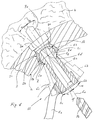
Zur Verankerung von Implantaten, wie künstlichen Hüftgelenkpfannen, sind Löcher 7a in das Knochenmaterial 4 zu bohren. Dabei dürfen die Bohrachsen 5b,5c maximal um einen Winkel α von einer normal zum Verankerungskörper 3 verlaufenden Achse 5a abweichen. Eine Vorrichtung 12 zum Bestimmen des Verlaufs von Bohrungen 7a im Knochen 4 besteht aus einer Bohrlehre 1 mit Bohrbüchse 1c und Handgriff 1a sowie einer gelenkig mit der Bohrbüchse 1c verbundenen Hülse 2. Die Hülse 2 weist eine Auflagefläche 2b sowie ev. einen Fortsatz 2h auf, der formschlüssig auf ein Durchgangsloch 3a im Verankerungskörper 3 auflegbar ist. Während dem Aufliegen der Hülse 2 auf dem Durchgangsloch 3a lässt sich die Bohrbüchse 1c in einem festgelegten Winkelbereich α bewegen, wobei ein Begrenzungsanschlag 2a der Hülse 2 sowie ein Begrenzungsanschlag 1g der Bohrbüchse 1c den Winkelbereich α begrenzen.For anchoring implants, such as artificial acetabular cups,
Im folgenden wird die Erfindung anhand von Ausführungsbeispielen beschrieben. Es zeigen:
- Fig. 1
- eine auf einen Verankerungskörper aufgesetze Bohrlehre;
- Fig. 2
- eine zerlegte Bohrlehre.
- Fig. 1
- a drilling jig placed on an anchoring body;
- Fig. 2
- a disassembled drilling jig.
Fig. 2 zeigt eine Vorrichtung 12 zum Bestimmen des Verlaufs von Bohrungen, die im zerlegten Zustand aus zwei Teilen, einer Bohrlehre 1 sowie einer Hülse 2 besteht. Die Bohrlehre 1 besteht aus einer Bohrbüchse 1c, die in Richtung der Bohrachse 5a einen zylinderförmigen Führungskanal 1f für Bohrer 7b aufweist. An einem Ende der Bohrbüchse 1c ist ein Handgriff 1a befestigt, durch den die Lage der Bohrbüchse 1c und somit die Richtung der Bohrachse 5a manuell vorgebbar ist. Am entgegengesetzten Ende des Führungskanales 1f, im Bereich der Austrittsöffnung 1h, bildet die Bohrbüchse 1c einen mindestens teilweise konvex ausgebildeten Bereich 1d, mit einer kugelförmigen Oberfläche 1k. Die kugelförmige Oberfläche 1k wird von der Hülse 2 im zusammengesetzten Zustand teilweise umfasst, so dass sich eine kugelgelenkartige Verbindung zwischen der Bohrbüchse 1c und der Hülse 2 ergibt, mit einem gemeinsamen Drehzentrum 5d. Die Hülse 2 weist eine Auflagefläche 2b auf, die mindestens teilweise auf eine Öffnung im Verankerungskörper 3 zu liegen kommt, wobei die Auflagefläche 2b vorteilhafterweise derart ausgestaltet ist, dass diese formschlüssig auf die Öffnung im Verankerungskörpers 3 aufliegt. Die Auflagefläche 2b kann einen Fortsatz 2h aufweisen, dessen äussere Form derart auf die Öffnung des Verankerungskörpers 3 angepasst ist, dass die Hülse 2 in einer genau definierten Lage auf die Öffnung des Verankerungskörpers 3 zu liegen kommt. Die äussere Form des Fortsatzes 2h kann zum Beispiel zylinderförmig oder konisch sein. Die Hülse 2 weist eine Austrittsöffnung 2c auf. Die Hülse 2 weist einen mindestens teilweise konkaven, insbesondere kugelförmigen Innenraum auf zur Bildung des Kugelgelenkes mit der Bohrlehre 1. Im getrennten Zustand der Vorrichtung 12 weist die Hülse 2 anschliessend an den konkaven Innenraum 2e einen zylinderförmigen Innenraum 2f auf. Nach dem Zusammenführen von Hülse 2 und Bohrbüchse 1c wird der zylinderförmige Innenraum 2f um die kugelförmige Oberfläche 1k gepresst, sodass sich eine nicht lösbare Verbindung in Form eines Kugelgelenkes zwischen Hülse 2 und Bohrlehre 1 ergibt mit gemeinsamem Drehzentrum 5d. Dabei wirkt ein Begrenzungsanschlag 2d der Hülse 2 derart auf ein Begrenzungsanschlag 1g der Bohrbüchse 1c, dass die Auslenkung zwischen Hülse 2 und Bohrbüchse 1c begrenzt ist.2 shows a
Fig. 1 zeigt die erfindungsgemässe Vorrichtung 12 zum Bestimmen des Verlauf von Bohrungen 7a im Zusammenhang mit der Implantation eines Verankerungskörpers 3 für Hüftgelenkpfannen. Nachdem eine kugelkalottenförmige Ausnehmung in das Knochenmaterial 4 getrieben ist, wird der Verankerungskörper 3 der Hüftgelenkpfanne in die Ausnehmung eingebracht. Danach werden Löcher 7a in den Knochen 4 gebohrt, die zur Aufnahme von Schrauben dienen, um das Implantat 3 im Knochen 4 zu verankern. Dargestellt ist ein Verankerungskörper 3 mit einem Durchgangsloch 3a, das sich gegen die dem Knochen abgewandte Seite hin verbreitert und eine Auflagefläche 3b bildet, auf die der Kopf der Schraube zu liegen komm. Zur Bestimmung der Bohrrichtung 5a des Bohrers 7b gelangt die Vorrichtung 12 zur Anwendung. Die Auflagefläche 2b der Hülse 2 ist derart ausgebildet, dass sie auf der Auflagefläche 3b des Verankerungskörpers 3 formschlüssig aufliegen kann. Die Hülse 2 wird über den Handgriff 1a zu einer Auflagefläche 3b geführt und derart in das Durchgangsloch 3a gedrückt, dass sich die Hülse 2 entsprechend der Auflagefläche 3b ausrichtet. Dabei kann ein Fortsatz 2h vorteilhaft sein, um die Lage der Hülse 2 bezüglich der Auflagefläche 3b präzise auszurichten und der Hülse einen zusätzlichen Halt zu verleihen. Bei einer derart festgelegten Lage der Hülse 2 lässt sich die Bohrbüchse 1c in einem durch die Begrenzungsanschläge 1g und 2a eingeschränkten Winkelbereich α bezüglich dem Drehzentrum 5d der Bohrachse schwenken. Die Bohrbüchse 1c ist in ihrer Mittellage mit Bohrachse 5a dargestellt, sowie in zwei Lagen maximaler Auslenkung, einer Stellung 6b der Bohrbüchse 1c mit Bohrachse 5b sowie einer Stellung 6c der Bohrbüchse 1c mit Bohrachse 5c. Somit lassen sich Bohrungen 7a in einem bezüglich der Auflagefläche 3b definierten Winkelbereich ausführen. Der eingeschränkte Winkelbereich der Bohrung 7a gewährleistet, dass ein auf der Auflagefläche 3b aufliegender Schraubenkopf nicht über die halbkugelförmige Innenfläche 3c des Verankerungskörpers 3 hinausragt. Ein nachträglich in den Verankerungskörper 3 eingefügter Pfannenkörper kann somit gleichmässig auf der Innenfläche 3c des Verankerungskörpers 3 aufliegen.1 shows the
Claims (9)
Priority Applications (2)
| Application Number | Priority Date | Filing Date | Title |
|---|---|---|---|
| DE59310213T DE59310213D1 (en) | 1993-03-05 | 1993-03-05 | Device for determining the course of bores in bones |
| EP19930810167 EP0613658B1 (en) | 1993-03-05 | 1993-03-05 | Apparatus for determining the course of drill-holes in bone |
Applications Claiming Priority (1)
| Application Number | Priority Date | Filing Date | Title |
|---|---|---|---|
| EP19930810167 EP0613658B1 (en) | 1993-03-05 | 1993-03-05 | Apparatus for determining the course of drill-holes in bone |
Publications (2)
| Publication Number | Publication Date |
|---|---|
| EP0613658A1 true EP0613658A1 (en) | 1994-09-07 |
| EP0613658B1 EP0613658B1 (en) | 2001-09-12 |
Family
ID=8214926
Family Applications (1)
| Application Number | Title | Priority Date | Filing Date |
|---|---|---|---|
| EP19930810167 Expired - Lifetime EP0613658B1 (en) | 1993-03-05 | 1993-03-05 | Apparatus for determining the course of drill-holes in bone |
Country Status (2)
| Country | Link |
|---|---|
| EP (1) | EP0613658B1 (en) |
| DE (1) | DE59310213D1 (en) |
Cited By (10)
| Publication number | Priority date | Publication date | Assignee | Title |
|---|---|---|---|---|
| WO2000074604A1 (en) * | 1999-06-02 | 2000-12-14 | Australian Surgical Design And Manufacture Pty Limited | Acetabular component of total hip replacement assembly |
| US6712857B1 (en) | 1999-06-02 | 2004-03-30 | Australian Surgical Design And Manufacture Pty Limited | Acetabular component of total hip replacement assembly |
| GB2423021A (en) * | 2005-02-15 | 2006-08-16 | Biomet Uk Ltd | A surgical guide jig with an expanding spherical joint |
| FR2928259A1 (en) * | 2008-03-07 | 2009-09-11 | D L P Sarl | MATERIAL FOR THE REDUCTION OF A FRACTURE, ESPECIALLY A DISTAL RADIUS FRACTURE |
| GB2475491A (en) * | 2009-11-18 | 2011-05-25 | Biomet Uk Ltd | Alignment tool for a femoral drill guide |
| WO2013155130A1 (en) * | 2012-04-10 | 2013-10-17 | The Cleveland Clinic Foundation | Directed structure placement guide |
| DE102012104651A1 (en) | 2012-05-30 | 2013-12-05 | Aesculap Ag | Implant kit for anchoring of implants in acetabulum bone of human body, has swivel angle simulation-extension structure which is formed and integrally adjoined in axial extension of drill guide sleeve |
| CN104080410A (en) * | 2012-01-26 | 2014-10-01 | 史密夫和内修有限公司 | Implant fixation member holder |
| US20220183702A1 (en) * | 2018-01-30 | 2022-06-16 | Conmed Corporation | Drill guide assembly |
| WO2024018402A1 (en) * | 2022-07-21 | 2024-01-25 | Arthrex, Inc. | Apparatus and method for fastener alignment of an orthopedic implant |
Families Citing this family (1)
| Publication number | Priority date | Publication date | Assignee | Title |
|---|---|---|---|---|
| DE10261813B4 (en) * | 2002-12-19 | 2004-10-28 | Eska Implants Gmbh & Co. | Centering aid for a joint head cap implant of an artificial hip joint |
Citations (5)
| Publication number | Priority date | Publication date | Assignee | Title |
|---|---|---|---|---|
| US2181746A (en) * | 1939-02-04 | 1939-11-28 | John R Siebrandt | Combination bone clamp and adjustable drill guide |
| US3017887A (en) * | 1960-01-19 | 1962-01-23 | William T Heyer | Stereotaxy device |
| WO1985002535A1 (en) | 1983-12-16 | 1985-06-20 | Protek Ag | Artificial joint cavity |
| US4599999A (en) * | 1984-06-11 | 1986-07-15 | Synthes Ag | Drill guide for use with surgical compression plates |
| US5112336A (en) * | 1991-05-14 | 1992-05-12 | Intermedics Orthopedics, Inc. | Drill guide and template for prosthetic devices |
-
1993
- 1993-03-05 EP EP19930810167 patent/EP0613658B1/en not_active Expired - Lifetime
- 1993-03-05 DE DE59310213T patent/DE59310213D1/en not_active Expired - Fee Related
Patent Citations (5)
| Publication number | Priority date | Publication date | Assignee | Title |
|---|---|---|---|---|
| US2181746A (en) * | 1939-02-04 | 1939-11-28 | John R Siebrandt | Combination bone clamp and adjustable drill guide |
| US3017887A (en) * | 1960-01-19 | 1962-01-23 | William T Heyer | Stereotaxy device |
| WO1985002535A1 (en) | 1983-12-16 | 1985-06-20 | Protek Ag | Artificial joint cavity |
| US4599999A (en) * | 1984-06-11 | 1986-07-15 | Synthes Ag | Drill guide for use with surgical compression plates |
| US5112336A (en) * | 1991-05-14 | 1992-05-12 | Intermedics Orthopedics, Inc. | Drill guide and template for prosthetic devices |
Cited By (17)
| Publication number | Priority date | Publication date | Assignee | Title |
|---|---|---|---|---|
| US6712857B1 (en) | 1999-06-02 | 2004-03-30 | Australian Surgical Design And Manufacture Pty Limited | Acetabular component of total hip replacement assembly |
| US7371261B2 (en) | 1999-06-02 | 2008-05-13 | Advanced Surgical Design & Manufacture Ltd. | Acetabular component of total hip replacement assembly |
| WO2000074604A1 (en) * | 1999-06-02 | 2000-12-14 | Australian Surgical Design And Manufacture Pty Limited | Acetabular component of total hip replacement assembly |
| GB2423021A (en) * | 2005-02-15 | 2006-08-16 | Biomet Uk Ltd | A surgical guide jig with an expanding spherical joint |
| FR2928259A1 (en) * | 2008-03-07 | 2009-09-11 | D L P Sarl | MATERIAL FOR THE REDUCTION OF A FRACTURE, ESPECIALLY A DISTAL RADIUS FRACTURE |
| WO2009115741A2 (en) * | 2008-03-07 | 2009-09-24 | D.L.P. | Equipment for reducing a fracture, in particular a fracture situated in the area of the epiphyses |
| WO2009115741A3 (en) * | 2008-03-07 | 2009-11-19 | D.L.P. | Equipment for reducing a fracture, in particular a fracture situated in the area of the epiphyses |
| GB2475491A (en) * | 2009-11-18 | 2011-05-25 | Biomet Uk Ltd | Alignment tool for a femoral drill guide |
| EP2806808A4 (en) * | 2012-01-26 | 2015-11-04 | Smith & Nephew Inc | Implant fixation member holder |
| AU2013212161B2 (en) * | 2012-01-26 | 2017-10-05 | Smith & Nephew, Inc. | Implant fixation member holder |
| CN104080410A (en) * | 2012-01-26 | 2014-10-01 | 史密夫和内修有限公司 | Implant fixation member holder |
| WO2013155130A1 (en) * | 2012-04-10 | 2013-10-17 | The Cleveland Clinic Foundation | Directed structure placement guide |
| US9033990B2 (en) | 2012-04-10 | 2015-05-19 | The Cleveland Clinic Foundation | Directed structure placement guide |
| CN104271053A (en) * | 2012-04-10 | 2015-01-07 | 克利夫兰临床基金会 | Directed structure placement guide |
| DE102012104651A1 (en) | 2012-05-30 | 2013-12-05 | Aesculap Ag | Implant kit for anchoring of implants in acetabulum bone of human body, has swivel angle simulation-extension structure which is formed and integrally adjoined in axial extension of drill guide sleeve |
| US20220183702A1 (en) * | 2018-01-30 | 2022-06-16 | Conmed Corporation | Drill guide assembly |
| WO2024018402A1 (en) * | 2022-07-21 | 2024-01-25 | Arthrex, Inc. | Apparatus and method for fastener alignment of an orthopedic implant |
Also Published As
| Publication number | Publication date |
|---|---|
| EP0613658B1 (en) | 2001-09-12 |
| DE59310213D1 (en) | 2001-10-18 |
Similar Documents
| Publication | Publication Date | Title |
|---|---|---|
| DE19858889B4 (en) | Fixation system for bones | |
| DE19518530B4 (en) | Instrument for insertion and fixation of an intramedullary nail | |
| DE69631344T2 (en) | DRILLING GAUGE INSTRUMENT | |
| EP0917449B1 (en) | Device for attaching fractured hip-joint heads | |
| DE69629596T2 (en) | ADJUSTABLE CLAMP FOR A BONE FIXING DEVICE | |
| DE2838348C2 (en) | Device for forming a bone opening | |
| EP1311198B1 (en) | Device for connecting a bone fixation element to a longitudinal rod | |
| EP0613657B1 (en) | Fixation pin | |
| EP0554210B1 (en) | Set of parts for an artificial hip acetabular cup | |
| DE60220175T2 (en) | DEVICE FOR ROTATING STABILIZATION OF BONE SEGMENTS | |
| EP1393697B1 (en) | Operating system | |
| DE69333281T2 (en) | Fastening device for a hip joint prosthesis | |
| EP0118778B1 (en) | Fixing nail | |
| WO1998052482A1 (en) | Device for connecting a longitudinal support with a pedicle screw | |
| EP0370204A1 (en) | Drilling device for producing a drilled hole with a recess | |
| EP0619990A1 (en) | Kit for an artificial joint cup, especially an acetabular cup | |
| WO2004030549A1 (en) | Device for fixing bones | |
| WO1998004217A1 (en) | Implant for bonding two adjacent vertebrae of the vertebral column | |
| EP0613658B1 (en) | Apparatus for determining the course of drill-holes in bone | |
| DE3339259C1 (en) | Device for the positioning of a surgical drilling tool | |
| DE60004978T2 (en) | combination tool | |
| EP0663193A1 (en) | Artificial hip acetabular cup | |
| DE3245680C2 (en) | Distal aiming device for an interlocking nail | |
| DE102006002211B4 (en) | Polyaxial alignable stabilizing element for endoprostheses | |
| EP2277466A1 (en) | Bone anchoring element |
Legal Events
| Date | Code | Title | Description |
|---|---|---|---|
| PUAI | Public reference made under article 153(3) epc to a published international application that has entered the european phase |
Free format text: ORIGINAL CODE: 0009012 |
|
| AK | Designated contracting states |
Kind code of ref document: A1 Designated state(s): CH DE FR GB IT LI |
|
| 17P | Request for examination filed |
Effective date: 19950207 |
|
| K1C3 | Correction of patent application (complete document) published |
Effective date: 19940907 |
|
| RAP1 | Party data changed (applicant data changed or rights of an application transferred) |
Owner name: SULZER ORTHOPAEDIE AG |
|
| 17Q | First examination report despatched |
Effective date: 19990324 |
|
| GRAG | Despatch of communication of intention to grant |
Free format text: ORIGINAL CODE: EPIDOS AGRA |
|
| RBV | Designated contracting states (corrected) |
Designated state(s): CH DE FR GB IT LI |
|
| GRAG | Despatch of communication of intention to grant |
Free format text: ORIGINAL CODE: EPIDOS AGRA |
|
| GRAH | Despatch of communication of intention to grant a patent |
Free format text: ORIGINAL CODE: EPIDOS IGRA |
|
| GRAH | Despatch of communication of intention to grant a patent |
Free format text: ORIGINAL CODE: EPIDOS IGRA |
|
| GRAA | (expected) grant |
Free format text: ORIGINAL CODE: 0009210 |
|
| AK | Designated contracting states |
Kind code of ref document: B1 Designated state(s): CH DE FR GB IT LI |
|
| REG | Reference to a national code |
Ref country code: CH Ref legal event code: NV Representative=s name: SULZER MANAGEMENT AG Ref country code: CH Ref legal event code: EP |
|
| GBT | Gb: translation of ep patent filed (gb section 77(6)(a)/1977) |
Effective date: 20010912 |
|
| REF | Corresponds to: |
Ref document number: 59310213 Country of ref document: DE Date of ref document: 20011018 |
|
| REG | Reference to a national code |
Ref country code: GB Ref legal event code: IF02 |
|
| ET | Fr: translation filed | ||
| PGFP | Annual fee paid to national office [announced via postgrant information from national office to epo] |
Ref country code: GB Payment date: 20020222 Year of fee payment: 10 |
|
| PGFP | Annual fee paid to national office [announced via postgrant information from national office to epo] |
Ref country code: CH Payment date: 20020225 Year of fee payment: 10 |
|
| PGFP | Annual fee paid to national office [announced via postgrant information from national office to epo] |
Ref country code: DE Payment date: 20020309 Year of fee payment: 10 |
|
| PGFP | Annual fee paid to national office [announced via postgrant information from national office to epo] |
Ref country code: FR Payment date: 20020315 Year of fee payment: 10 |
|
| PLBE | No opposition filed within time limit |
Free format text: ORIGINAL CODE: 0009261 |
|
| STAA | Information on the status of an ep patent application or granted ep patent |
Free format text: STATUS: NO OPPOSITION FILED WITHIN TIME LIMIT |
|
| 26N | No opposition filed | ||
| PG25 | Lapsed in a contracting state [announced via postgrant information from national office to epo] |
Ref country code: GB Free format text: LAPSE BECAUSE OF NON-PAYMENT OF DUE FEES Effective date: 20030305 |
|
| PG25 | Lapsed in a contracting state [announced via postgrant information from national office to epo] |
Ref country code: LI Free format text: LAPSE BECAUSE OF NON-PAYMENT OF DUE FEES Effective date: 20030331 Ref country code: CH Free format text: LAPSE BECAUSE OF NON-PAYMENT OF DUE FEES Effective date: 20030331 |
|
| PG25 | Lapsed in a contracting state [announced via postgrant information from national office to epo] |
Ref country code: DE Free format text: LAPSE BECAUSE OF NON-PAYMENT OF DUE FEES Effective date: 20031001 |
|
| GBPC | Gb: european patent ceased through non-payment of renewal fee |
Effective date: 20030305 |
|
| REG | Reference to a national code |
Ref country code: CH Ref legal event code: PL |
|
| PG25 | Lapsed in a contracting state [announced via postgrant information from national office to epo] |
Ref country code: FR Free format text: LAPSE BECAUSE OF NON-PAYMENT OF DUE FEES Effective date: 20031127 |
|
| REG | Reference to a national code |
Ref country code: FR Ref legal event code: ST |
|
| PG25 | Lapsed in a contracting state [announced via postgrant information from national office to epo] |
Ref country code: IT Free format text: LAPSE BECAUSE OF NON-PAYMENT OF DUE FEES;WARNING: LAPSES OF ITALIAN PATENTS WITH EFFECTIVE DATE BEFORE 2007 MAY HAVE OCCURRED AT ANY TIME BEFORE 2007. THE CORRECT EFFECTIVE DATE MAY BE DIFFERENT FROM THE ONE RECORDED. Effective date: 20050305 |