EP0614070A1 - An electronic pedometer with blood pulse counting device - Google Patents
An electronic pedometer with blood pulse counting device Download PDFInfo
- Publication number
- EP0614070A1 EP0614070A1 EP94301068A EP94301068A EP0614070A1 EP 0614070 A1 EP0614070 A1 EP 0614070A1 EP 94301068 A EP94301068 A EP 94301068A EP 94301068 A EP94301068 A EP 94301068A EP 0614070 A1 EP0614070 A1 EP 0614070A1
- Authority
- EP
- European Patent Office
- Prior art keywords
- pulse wave
- pulse
- signal
- action noise
- calculating
- Prior art date
- Legal status (The legal status is an assumption and is not a legal conclusion. Google has not performed a legal analysis and makes no representation as to the accuracy of the status listed.)
- Granted
Links
Images


Classifications
-
- G—PHYSICS
- G01—MEASURING; TESTING
- G01C—MEASURING DISTANCES, LEVELS OR BEARINGS; SURVEYING; NAVIGATION; GYROSCOPIC INSTRUMENTS; PHOTOGRAMMETRY OR VIDEOGRAMMETRY
- G01C22/00—Measuring distance traversed on the ground by vehicles, persons, animals or other moving solid bodies, e.g. using odometers, using pedometers
- G01C22/006—Pedometers
-
- A—HUMAN NECESSITIES
- A61—MEDICAL OR VETERINARY SCIENCE; HYGIENE
- A61B—DIAGNOSIS; SURGERY; IDENTIFICATION
- A61B5/00—Measuring for diagnostic purposes; Identification of persons
- A61B5/02—Detecting, measuring or recording pulse, heart rate, blood pressure or blood flow; Combined pulse/heart-rate/blood pressure determination; Evaluating a cardiovascular condition not otherwise provided for, e.g. using combinations of techniques provided for in this group with electrocardiography or electroauscultation; Heart catheters for measuring blood pressure
- A61B5/024—Detecting, measuring or recording pulse rate or heart rate
- A61B5/02438—Detecting, measuring or recording pulse rate or heart rate with portable devices, e.g. worn by the patient
Abstract
Description
- This invention relates to an electronic pedometer with pulse counting device which is equipped with a pulse counting function as well as a pedometer function. The pulse counting device is suitable for measuring the heart rate.
- Fig. 4 is illustrative of a functional block diagram which shows the operations of an electronic pedometer with a pulse counting device in accordance with the prior art. Pulse wave detecting means 40 detects a pulse wave signal and outputs the detected signal to an amplify wave shaping means 41. The amplify wave shaping means 41 outputs to a pulse wave calculating means 42, a pulse wave signal which has its waveform shaped by the amplify wave shaping means 41. The pulse wave calculating means 42 calculates the cycle of the pulse wave signal input thereto based on a standard signal output by a timing pulse generating means 45. The pulse wave calculating means 42 outputs to a display selecting means 47, the pulse wave information which has been calculated. Step number data detecting means 43 detects a step signal and outputs to a wave shaping means 44, the step signal which has been detected. The wave shaping means 44 shapes the wave of the step signal which has been input and outputs to a step number data calculating means 46, the wave-shaped step signal. The step number data calculating means 46 calculates the cycle of the step signal which has been input based on a standard signal which is output from the timing pulse generating means 45. The step number data calculating means outputs into the display selecting means 47 the calculated step information. The display selecting means 47 above selects from the pulse wave information and step number information, both of which have been input to it, by referring to the output level which is output by a selecting
switch 49, and outputs to adisplaying means 48. The displaying means 48 displays the information which is input. - Such an electronic pedometer with pulse counting device as mentioned above is disclosed in Japanese Patent Publication No. JP-A-56-79382 (1981). In this electronic pedometer with pulse counting device, the pulse sensor by which a pulse wave and its number is measured and step number sensor which measures the number of steps are equipped separately. Thus the pulse wave measuring function and the step number measuring function can be used in the way that both functions are manually selected alternately by the selecting switch.
- Increasingly, people who wish to do self health control through sporting activities, such as jogging. In these activities pulse measuring device and step number devices are widely used for gaining the information for self health control.
- But the pedometer with the pulse counting device in the prior art has the demerit when designing smaller pedometers or portable one. In addition, such pedometers need more man-hours in the manufacturing process since both sensors of the pulse wave counting and step number counting or detecting are equipped separately. Finally, in its practical use, it is not easy to use, since the selecting switch has to be manually set.
- An objection of this invention is to propose a handy, portable electronic pedometer with pulse counting device which is easy in practice to use.
- According to the present invention, there is provided an electronic pedometer having:
a pulse wave detecting means for detecting the pulse wave of a mammal;
a display for displaying a pulse rate and step number of the mammal; characterised by
a pulse wave level storing means for storing data correlating pulse waves with type of movement; and
a pulse wave calculate control means coupled to said display and coupled to said pulse wave detecting means and said pulse wave level storing means for calculating a step number from the data stored in the pulse wave level storing means and the pulse wave received. - For the first means to solve the problem above, the invention includes pulse wave level storing means which stores a predetermined pulse wave width level set before hand with which a pulse wave detecting means detects pulse waves, action noise detecting means which detects action noise by comparing the output of the pulse wave detecting means with the output of the pulse wave level storing means, constant value storing means which stores various constant values for the pulse wave calculating means, and pulse wave calculate control means which detects and controls calculating actions through determining various constant values of the pulse wave calculating means out of both of the output of the action noise detecting means and output of the constant value storing means. This invention realises both functions of the pulse wave measuring and the step number measuring by the construction above.
- And for the second means to solve the problem above, the invention includes action noise detect counting means which measures the duration in which output of the action noise detecting means becomes stable, and pulse wave calculate control means which selects and controls calculating operations through determining the various constant values of the pulse wave calculating means out of the outputs of the action noise detect counting means and the constant value storing means. This invention realises pulse wave measuring and step number measuring. That is to say, a measuring device which automatically switches alternately between selection of the pulse wave and the step number.
- Embodiments of the present invention will now be described with reference to the accompanying drawings, of which:
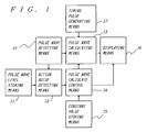
- Fig. 1 shows a functional block diagram of representative constitutions in this invention;
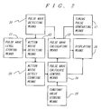
- Fig. 2 shows another functional block diagram of representative constitutions in this invention;
- Fig. 3 shows yet another functional block diagram of the representative constitutions in this invention;
- Fig. 4 shows a functional block diagram of a pedometer with pulse count device in the prior art;
- Fig. 5 shows an example of a displayed identified signal;
- Fig. 6 shows an example of graphical display;
- Fig. 7 shows a functional block diagram in a first embodiment of the pedometer with pulse count device in this invention;
- Fig. 8 shows a functional block diagram in another embodiment of the pedometer with pulse count device in this invention;
- Fig. 9 shows a circuit drawing of an embodiment of the pedometer with pulse count device in this invention;
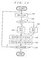
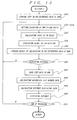
- Fig. 10 shows a flow chart of an amplifying ratio setting procedure in a CPU in an embodiment of the pedometer with pulse count device in this invention;
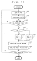
- Fig. 11 shows a flow chart of an action noise signal detecting procedure in a CPU in an embodiment of the pedometer with pulse count device;
- Fig. 12 shows a flow chart of a graphically displaying procedure in a CPU of an embodiment of the pedometer with pulse count device in this invention; and
- Fig. 13 shows a flow chart of a distance calculating and displaying procedure in a CPU of an embodiment of the pedometer with pulse count device in this invention.
- Fig. 1 shows a functional block diagram which represents an example of a typical constitution of this invention. The pulse wave detecting means 10 detects a pulse wave of a human body and outputs a pulse wave signal which has been detected to an action noise detecting means 12 and to a pulse
wave calculating means 13. The action noise detecting means 12 outputs an action noise signal to a pulse wave calculate control means 14 by comparing the stored contents in a pulse wave level storing means 11 with the pulse wave signal which has been input. The pulse wave calculate control means 14, based on the action noise input to it, selects various constant values stored in a constant value storing means 15, and outputs the various constant values and the result of its selection to the pulse wave calculatingmeans 13 and adisplaying means 16. The pulse wave calculating means 13 calculates a result on the basis of the pulse wave signal received by it using a standard signal which a timing pulse generating means 17 outputs and the various constant values which the pulse wave calculate control means 14 outputs, and output the calculated result to the displaying means 16. - The pulse wave which the pulse wave detecting means 10 detects is output to not only the pulse wave calculating means 13 but also to the action noise detecting means 12 in case of the users being quiet when detecting the pulse or when detecting the step signal of his/her swinging an arm in case of his/her walking so as to be able to determine the step number.
- The signal width level which is output from the pulse wave detecting means 10 is different from each other depending upon whether the user is keeping quiet or walking. The action noise detecting means 12 determines which of the signals is received, due to the stored level in the pulse wave level storing means 11. Accordingly, the displaying means 16 displays pulse wave information based on the resultant output of the pulse wave calculate control means 14 in case of the user keeping quiet, or step number information [as well as its identified signal 50 at the same time] in case of the user walking. The action noise detecting means 12 can detect not only walking but also jogging or running according to the stored level in the pulse wave level storing means 11.
- Fig. 2 shows a functional block diagram which represents another example of the typical constitution of this invention. The pulse wave detecting means 10 detects a pulse wave of a human body and outputs the detected pulse wave signal to the action noise detecting means 12 and to the pulse wave calculating means 13. The action noise detecting means 12 outputs the action noise signal to an action noise detect counting means 20 by comparing the pulse wave signal with the stored contents in the pulse wave level storing means 11. The action noise detect counting means 20 measures the duration in which the action noise input into it maintains the predetermined level, and outputs it as the action noise measuring signal to the pulse wave calculate control means 14.
- The pulse wave calculate control means 14 selects, based on the action noise signal input to it, the various constant values stored in the constant value storing means 15, and outputs the various constant values and the selected result to the pulse wave calculating
means 13 and to the displayingmeans 16. The pulse wave calculating means 13 calculates the result using the pulse wave signal input to it, the standard signal output by the timing pulse generating means 17 and the various constant values outputs by the pulse wave calculate control means 14, to output the result into the displayingmeans 16. - Since the action noise signal, which the action noise detect counting means 20 detects, is maintained, its action noise signal level is not affected by momentary or instant change in the action noise signal itself. Thus what is displayed on the displaying
means 16, does not vary momentarily or with instance. - Fig. 3 shows a functional block diagram of another example of a typical constitution of this invention. The pulse
wave detecting means 10 detects a pulse wave of a human body, and outputs its signal to the pulse wave calculating means 13 and to the actionnoise detecting means 12. The actionnoise detecting means 12 compares a pulse wave signal input to it, with the stored contents in the pulse wave level storing means 13, and outputs the action noise signal to the pulse wave calculated control means 14. The pulse wave calculates control means 14 selects, based on the action noise signal input to it, the various constant values stored in the constant value storing means 15, and outputs the various constant values to the pulsewave calculating means 13. The pulse wave calculating 13 calculates a result using the pulse wave signal input to it and both the standard signal output by the timing pulse generating means 17 and the various constant values output by the pulse wave calculate control means 14, and outputs the result to the calculated product storing means 30. - The calculated product storing means 30 not only stores the result but from time to time, also, if necessary, outputs the stored contents to the displaying
means 16, a graph calculating means 31 and a distance calculating means 33. The graph calculating means 31 calculates data, using the calculated and stored contents input to it, for the purpose of a display time-series graph, and outputs the calculated result to the displayingmeans 16. The distance calculating means 33 calculates the distance which the user has walked using the calculated and stored contents of the calculated product storing means 30 and the stored contents in a step data storing means 32, outputs the calculated result to the displayingmeans 16. - By means of the graph calculating means 31 and the distance calculating means 33, not only the display of the pulse wave measuring function and the step number measuring function, but also the display of time series changes in the above can be realised and usage as a distance finder can be realised, too.
- Embodiments of this invention are explained hereinafter based on the drawings.
- Fig. 7 shows a functional block diagram of the first embodiment of an electronic pedometer with pulse counting device of this invention. The
pulse wave sensor 700 detects pulse waves of a human body, and output the pulse wave signal which has been detected to thefirst amplifying circuit 701. Thefirst amplifying circuit 701 amplifies the pulse wave signal and outputs to thesecond amplifying circuit 705 and to the comparingcircuit 706. The comparingcircuit 706 compares the pulse wave signal level input to it with the electric voltage level standard stored in the standardvoltage setting circuit 710 and outputs to aCPU 708 the compared result as the detected action noise signal.CPU 708 outputs, based on this comparison result above, an amplifying ratio setting signal to an amplifyingratio setting circuit 704 and outputs at the same time an identified signal 50 as shown in Fig. 5 to a displayingelement 709. According to the identified signal 50, the user can identify instantly which datum is measured now in the system. - The amplifying
ratio setting circuit 704 sets the signal amplifying ratio for thesecond amplifying circuit 705, based on the amplifying ratio setting signal. Thesecond amplifying circuit 705 improves the S/N ratio of the pulse wave signal input to it by way of a filter circuit etc., and amplifies the pulse wave signal in accordance with the amplifying ratio set by the amplifyingratio setting circuit 704. Thesecond amplifying circuit 705 then outputs the amplified pulse wave signal above to awave shaping circuit 707. Thewave shaping circuit 707 transforms the pulse wave signal which is input as an analogue signal into that which is a digital signal, and outputs the digital signal to theCPU 708.CPU 708 calculates the cycle of the pulse wave signal which is transformed to digital by way of thewave shaping circuit 707, based on the timing signal of adividing circuit 703, and outputs the result to the displaying element, such as a liquid crystal panel etc. - Fig. 9 shows an embodiment of a concrete circuit of a functional block diagram showing in Fig. 7. The
pulse wave sensor 700 detects changes in the blood stream by way of optical means. That is to say, a light intercepting element TR1, such as photo-transistor etc, detects transmitted light or reflected light from a luminescent element D1, such as an LED etc. For example, thesensor 700 is finger-tip shaped and is placed on a finger tip. Inside thepulse wave sensor 700 is equipped with a sensor holding component have a contact with a finger tip portion at predetermined pressure. Thispulse wave sensor 700 can detect the blood stream state on the finger-tip. - Another pulse wave detecting means such as a microphone, can also detect the cardiac second as the pulsation. Like above, the
pulse wave sensor 700 detects the pulse wave signal from a human body, and outputs it to thefirst amplifying circuit 701. Thefirst amplifying circuit 701 rejects the direct current component from the pulse wave signal which it receives by way of filter. The filter comprises a condenser C1 and a resistor R3, and amplifiers it through a non-converted amplifier A1 by way of operational amplifier. The first amplifying circuit then outputs the pulse wave signal into thesecond amplifying circuit 705 and to the comparingcircuit 706. The standardvoltage setting circuit 710 sets the standard voltage by way of the resisters R13 and R14, and outputs the standard voltage to the comparingcircuit 706. - The comparing
circuit 706 comprises window-comparators A5 and A6 for the purpose of judging the width level of the pulse wave signal which is input. The width level is indicative of whether the holder is keeping quiet or whether he/she is swinging the arms. The judgement is done by comparing the pulse wave signal with the standard voltage set according to the resistive dividing ratio of resistors R13 and R14. In this case, the judgement is as follows: output from the gate circuit G1 is at VCC level in case of the user keeping quiet, and it is at GND level in case of the user swinging arms: i.e. in walking. If the amplifying ratio at thefirst amplifying circuit 701 and/or resistive dividing ratio at the standardvoltage setting circuit 710 is changed, then as well as the user being detected as walking, one can also detect whether the user is running. - Fig. 10 shows a flow chart of a procedure when the
CPU 708 controls the amplifyingratio setting circuit 704, based on the action noise signal P/W which is output from the comparingcircuit 706, and when the pulse wave signal cycle is output to the displaying element. In Fig. 10 and Fig. 9,CPU 708 reads the signal level at input port IP2 terminal and judges its level (S101, S102). In case of GND level, the resistor R10 is selected by turning-on transistor TR3. In case of VCC level, the resistor R9 is selected by turning on transistor TR2 (S103, S104). - In Fig. 9, any noise component included in the pulse wave signal which is input to the
second amplifying circuit 705, is rejected by the filter circuit which comprises of resistors R6, and R7, condensers C2 and C3, and operational amplifier A2. After the rejection above, the pulse wave signal is amplified by way of converted amplifier which comprises of operational amplifier A3 and resistors R8, R9 and R10. The pulse wave signal is converted to digital throughwave shaping circuit 707 and then output to input port IP1 terminal ofCPU 708 as PW pulse. At this occasion as shown in this embodiment, it is possible that noise is rejected adding a hysteresis characteristic by way of positive feedback of the operational amplifier output through resistor R12. - In Fig. 10,
CPU 708 calculates the PW pulse cycle received based on a standard signal (S105). To calculate this, the time difference between the former PW pulse and current PW pulse may be measured relatively simply or alternatively the number of input durations of PW pulse to be measured may be also accepted. Any result above is displayed at the displayingelement 709 as a number of signals for one minute (S106). After display, the measurement is continued if in measuring mode. Alternatively automatic stoppage of measurement after measuring for a certain period of time can also be arranged. - Fig. 8 shows a functional block diagram of the second embodiment of the electronic pedometer with pulse count device in this invention. In this embodiment,
RAM 800 for datum memory is added. That is,RAM 800 is added to the pedometer with pulse count device shown in Fig. 7.RAM 800 is efficiently utilised so that the total memory area is divided to include, for example, PW pulse memory area, cycle calculating area, graphic datum memory area, step length memory area, and distance calculating area. - Fig. 11 shows a flow chart of the procedure which includes a stable duration of time during which action noise detecting signal P/W which is detected by comparing
circuit 706, is measured so that the amplifyingratio setting circuit 704 is controlled by the CPU action noise detecting signal P/W read from input port IP2, and if its level is at the same level as of the former one, then a period of time is counted. The time is counted in the time counting area which is divided beforehand inRAM 800. If the input level is different from that of the former, then the content to be counted is reset and is counted again from the first (S201). If the counted number is greater than a predetermined one, then the calculating and displaying procedure is followed as shown in Fig. 10 (S202). Due to the above procedure, the displayed content is not instantly altered on momentary changes in action noise, so that the user can be confident of using the pedometer. - Fig. 12 shows a flowchart of the procedure for displaying time series graphically for instance, the cycle calculation result of the detected pulse wave signal. After the cycle calculation and displaying procedure shown in Fig. 10, the result above is stored in the PW pulse memory which is part of RAM 800 (S300). After this, it is judged whether the display is in graphically displaying mode or not (S301). If the display is in the graphically displaying mode, data stored in
RAM 800 is converted to be displayable data in expected graph style after judging that the display is in the graphically displaying mode (S305). Then, for example as shown in Fig. 6, a time series graph is displayed (S306). By way of a change in the calculation procedure, any additionally flicker display of the smallest or the largest value may be done or alternatively the display may be swept so that display is not completed at once. - Fig. 13 shows a flow chart of the displaying procedure for the displaying
element 709 by way of distance calculation utilising step width datum and the cumulative step number stored inRAM 800. At first beforehand, the step width is memorised in the step width datum memory area in RAM 800 (S300). Next, after cycle calculation and its displaying procedure shown in Fig. 10, the result of calculation is stored in PW pulse memory area divided in RAM 800 (S300). After judging that the display is in distance displaying mode (S401), the memory is read to obtain the step width datum in RAM 800 (S402) and the cumulative stem number stored in the other area inRAM 800 is calculated (S403). The result is displayed on the displaying element 709 (S405). Not only the distance but also the time series shift type display of cumulative distance (S404) can graphically displayed by way of graphical display procedure shown in Fig. 12. - As explained above, a sensor can be used combining pulse wave and step number counting in the electronic pedometer with pulse count device in this invention. This leads to the realisation of smaller sizing and compact, portable types of product. By changing the standard voltage for judging the signal level detected, not only walking but also running can also be measured (this usage is called a pitchmeter). Therefore various kinds of multipurpose devices as shown above can be offered as a consequence of this invention.
- The aforegoing description has been given by way of example only and it will be appreciated by a person skilled in the art that modifications can be made without departing from the scope of the present invention.
Claims (6)
- An electronic pedometer having:
a pulse wave detecting means (10;700) for detecting the pulse wave of a mammal;
a display (16;709) for displaying a pulse rate and step number of the mammal; characterised by
a pulse wave level storing means (11; 710) for storing data correlating pulse waves with type of movement; and
a pulse wave calculate control means (14; 708) coupled to said display and coupled to said pulse wave detecting means and said pulse wave level storing means for calculating a step number from the data stored in the pulse wave level storing means and the pulse wave received. - An electronic pedometer with pulse counting device comprising:
pulse wave detecting means (10; 700) which detects pulse wave by way of pulse wave sensor;
timing pulse generating means (17; 703) which measures timing pulse;
pulse wave calculating means (13; 708) which receives and amplifies pulse wave that said pulse wave detecting means outputs and calculates pulse signal cycle based on the timing pulse signal which said timing pulse generating means generates;
pulse wave level storing means (11; 710) which stores pulse wave width level which through detection by pulse wave detecting means is set beforehand;
action noise detecting means (12; 706) which detects action noise through comparing pulse wave signal which is output by said pulse wave detecting means with what is stored in said pulse wave level storing means;
constant value storing means (15; 770) which stores various constant values with which said pulse wave calculating means calculates pulse wave signal;
pulse wave calculate control means (14; 708) which determines various constant values for said pulse wave calculating means out of stored contents in said constant value storing means and action noise signal which is output by said action noise detecting means, selects and controls calculating action on pulse wave and action; and
displaying means (16; 709) which receives pulse wave signal which is output by said pulse wave calculating means and displays information concerning pulse wave and movement action of human body. - An electronic pedometer as claimed in claim 1, further comprising:
action noise detect counting means (20; 705) which through receiving action noise signal which is output by said action noise detecting means measures the duration in which the action noise maintains a predetermined level; and in which the pulse wave calculate control means determines various constant values in said pulse wave calculating means based on the action noise measuring signal which said action noise detect counting means outputs. - An electronic pedometer with pulse counting device according to claim 2 or 3, wherein an identified signal is displayed on said displaying means by receiving a signal through which action noise is identifieed which is output by said pulse wave calculate control means.
- An electronic pedometer with pulse counting device according to claim 2, 3 or 4, further comprising:
calculated product storing means (30) which stores information concerning a pulse wave which said pulse wave calculating means outputs and action noise; and
graph calculating means (31) which calculates datum to be displayed for the purpose of time-series displayed in graph on said displaying means, of stored contents in said calculating product storing means. - An electronic pedometer with pulse counting device according to claim 2, 3, 4 or 5, further comprising:
step data storing means (32) which stores steps;
distance calculating means (33) which calculates distance which is walked through the steps above; and
said displaying means which displays the distance by receiving distance calculating signal which is output by said distance calculating means.
Applications Claiming Priority (2)
| Application Number | Priority Date | Filing Date | Title |
|---|---|---|---|
| JP32310/93 | 1993-02-22 | ||
| JP03231093A JP3220271B2 (en) | 1993-02-22 | 1993-02-22 | Pedometer with pulse meter |
Publications (2)
| Publication Number | Publication Date |
|---|---|
| EP0614070A1 true EP0614070A1 (en) | 1994-09-07 |
| EP0614070B1 EP0614070B1 (en) | 1998-06-17 |
Family
ID=12355372
Family Applications (1)
| Application Number | Title | Priority Date | Filing Date |
|---|---|---|---|
| EP94301068A Expired - Lifetime EP0614070B1 (en) | 1993-02-22 | 1994-02-14 | An electronic pedometer with blood pulse counting device |
Country Status (5)
| Country | Link |
|---|---|
| US (1) | US5475725A (en) |
| EP (1) | EP0614070B1 (en) |
| JP (1) | JP3220271B2 (en) |
| CN (1) | CN1096254C (en) |
| DE (1) | DE69411048T2 (en) |
Cited By (9)
| Publication number | Priority date | Publication date | Assignee | Title |
|---|---|---|---|---|
| EP0666055A2 (en) * | 1994-02-03 | 1995-08-09 | Omron Corporation | A pulsimeter provided with or without a pedometer |
| EP0729726A2 (en) * | 1995-02-20 | 1996-09-04 | Seiko Epson Corporation | Pulse rate meter |
| EP0730843A2 (en) * | 1995-02-20 | 1996-09-11 | Seiko Epson Corporation | A period and frequency measurement device |
| EP0733340A1 (en) * | 1995-03-23 | 1996-09-25 | Seiko Instruments Inc. | Pulse rate monitor |
| EP0803733A1 (en) * | 1995-10-18 | 1997-10-29 | Seiko Epson Corporation | Measuring instrument, portable electronic equipment and measuring method |
| FR2754723A1 (en) * | 1996-10-22 | 1998-04-24 | Faraglia Michel | PORTABLE DEVICE FOR AIDING HIKING |
| EP0761163A3 (en) * | 1995-08-31 | 1999-02-10 | Seiko Epson Corporation | Display method used in portable pulse measuring device |
| EP1369082A2 (en) * | 2002-03-14 | 2003-12-10 | Seiko Epson Corporation | Physical activity measurement apparatus |
| EP1895276A1 (en) * | 2006-08-29 | 2008-03-05 | Seiko Instruments Inc. | Pedometer |
Families Citing this family (37)
| Publication number | Priority date | Publication date | Assignee | Title |
|---|---|---|---|---|
| US6516284B2 (en) | 1994-11-21 | 2003-02-04 | Phatrat Technology, Inc. | Speedometer for a moving sportsman |
| US5636146A (en) | 1994-11-21 | 1997-06-03 | Phatrat Technology, Inc. | Apparatus and methods for determining loft time and speed |
| US6885971B2 (en) | 1994-11-21 | 2005-04-26 | Phatrat Technology, Inc. | Methods and systems for assessing athletic performance |
| US8280682B2 (en) | 2000-12-15 | 2012-10-02 | Tvipr, Llc | Device for monitoring movement of shipped goods |
| US7386401B2 (en) | 1994-11-21 | 2008-06-10 | Phatrat Technology, Llc | Helmet that reports impact information, and associated methods |
| US6266623B1 (en) | 1994-11-21 | 2001-07-24 | Phatrat Technology, Inc. | Sport monitoring apparatus for determining loft time, speed, power absorbed and other factors such as height |
| US6539336B1 (en) | 1996-12-12 | 2003-03-25 | Phatrat Technologies, Inc. | Sport monitoring system for determining airtime, speed, power absorbed and other factors such as drop distance |
| JP3905536B2 (en) * | 1995-03-23 | 2007-04-18 | セイコーインスツル株式会社 | Pulse meter control method |
| JPH09114955A (en) * | 1995-10-18 | 1997-05-02 | Seiko Epson Corp | Pitch meter |
| JP3564482B2 (en) * | 1996-03-22 | 2004-09-08 | セイコーエプソン株式会社 | Exercise intensity measurement device |
| JP3523978B2 (en) * | 1997-03-18 | 2004-04-26 | セイコーエプソン株式会社 | Pulse meter |
| US5976083A (en) * | 1997-07-30 | 1999-11-02 | Living Systems, Inc. | Portable aerobic fitness monitor for walking and running |
| US6473483B2 (en) | 1998-10-28 | 2002-10-29 | Nathan Pyles | Pedometer |
| US6175608B1 (en) | 1998-10-28 | 2001-01-16 | Knowmo Llc | Pedometer |
| EP1333755A4 (en) * | 2000-10-26 | 2005-03-09 | Healthetech Inc | Body supported activity and condition monitor |
| US7171331B2 (en) | 2001-12-17 | 2007-01-30 | Phatrat Technology, Llc | Shoes employing monitoring devices, and associated methods |
| US6791462B2 (en) | 2002-09-18 | 2004-09-14 | Sang J. Choi | Sleepy alarm system activated by heart pulse meter |
| US20040086001A1 (en) * | 2002-10-30 | 2004-05-06 | Miao George J. | Digital shaped gaussian monocycle pulses in ultra wideband communications |
| US6823036B1 (en) * | 2003-09-24 | 2004-11-23 | Yu-Yu Chen | Wristwatch-typed pedometer with wireless heartbeat signal receiving device |
| US20050195094A1 (en) * | 2004-03-05 | 2005-09-08 | White Russell W. | System and method for utilizing a bicycle computer to monitor athletic performance |
| JP2007024721A (en) * | 2005-07-19 | 2007-02-01 | Lube Corp | Flow rate detection device for flowing oil |
| US20070051842A1 (en) * | 2005-09-08 | 2007-03-08 | Pryor Anne M | Personal device with tether system and method of use |
| WO2007047889A2 (en) | 2005-10-18 | 2007-04-26 | Phatrat Technology, Llc | Shoe wear-out sensor, body-bar sensing system, unitless activity assessment and associated methods |
| JP4785553B2 (en) * | 2006-02-16 | 2011-10-05 | セイコーインスツル株式会社 | Pedometer |
| US8073984B2 (en) | 2006-05-22 | 2011-12-06 | Apple Inc. | Communication protocol for use with portable electronic devices |
| US7643895B2 (en) | 2006-05-22 | 2010-01-05 | Apple Inc. | Portable media device with workout support |
| US20070271116A1 (en) | 2006-05-22 | 2007-11-22 | Apple Computer, Inc. | Integrated media jukebox and physiologic data handling application |
| US9137309B2 (en) | 2006-05-22 | 2015-09-15 | Apple Inc. | Calibration techniques for activity sensing devices |
| US7813715B2 (en) | 2006-08-30 | 2010-10-12 | Apple Inc. | Automated pairing of wireless accessories with host devices |
| US7913297B2 (en) | 2006-08-30 | 2011-03-22 | Apple Inc. | Pairing of wireless devices using a wired medium |
| JP4885665B2 (en) * | 2006-09-21 | 2012-02-29 | セイコーインスツル株式会社 | Pedometer |
| JP4885664B2 (en) * | 2006-09-21 | 2012-02-29 | セイコーインスツル株式会社 | Pedometer |
| US7698101B2 (en) | 2007-03-07 | 2010-04-13 | Apple Inc. | Smart garment |
| JP4962195B2 (en) * | 2007-08-03 | 2012-06-27 | コニカミノルタオプティクス株式会社 | Pulse oximeter |
| KR101911218B1 (en) | 2012-10-30 | 2018-10-24 | 삼성전자주식회사 | Method and apparatus for calculating amount of exercise |
| US9314171B2 (en) * | 2013-07-31 | 2016-04-19 | Omron Healthcare Co., Ltd. | Blood pressure measurement device having function of determining rest condition of patient |
| CN106017504A (en) * | 2016-07-04 | 2016-10-12 | 紫光股份有限公司 | Step counting device based on ankle movement speed detection |
Citations (6)
| Publication number | Priority date | Publication date | Assignee | Title |
|---|---|---|---|---|
| JPS5679382A (en) * | 1979-11-30 | 1981-06-29 | Matsushita Electric Works Ltd | Pulsimeter and pedometer in common use |
| US4312358A (en) * | 1979-07-23 | 1982-01-26 | Texas Instruments Incorporated | Instrument for measuring and computing heart beat, body temperature and other physiological and exercise-related parameters |
| JPS60104286A (en) * | 1983-11-11 | 1985-06-08 | Seiko Instr & Electronics Ltd | Heart rate meter wrist watch provided with pedometer |
| US4807639A (en) * | 1985-08-31 | 1989-02-28 | Casio Computer Co., Ltd. | Pulse detection apparatus |
| US4962469A (en) * | 1988-04-18 | 1990-10-09 | Casio Computer Co., Ltd. | Exercise measuring instrument |
| US4974601A (en) * | 1988-09-05 | 1990-12-04 | University Of North Carolina At Charlotte | Portable heart monitor performing multiple functions |
Family Cites Families (4)
| Publication number | Priority date | Publication date | Assignee | Title |
|---|---|---|---|---|
| US4367752A (en) * | 1980-04-30 | 1983-01-11 | Biotechnology, Inc. | Apparatus for testing physical condition of a subject |
| US4566461A (en) * | 1983-02-15 | 1986-01-28 | Michael Lubell | Health fitness monitor |
| US4855942A (en) * | 1987-10-28 | 1989-08-08 | Elexis Corporation | Pedometer and/or calorie measuring device and method |
| JP2750339B2 (en) * | 1989-09-06 | 1998-05-13 | 株式会社マルタカ | Step counting device |
-
1993
- 1993-02-22 JP JP03231093A patent/JP3220271B2/en not_active Expired - Fee Related
-
1994
- 1994-02-02 US US08/191,017 patent/US5475725A/en not_active Expired - Fee Related
- 1994-02-14 EP EP94301068A patent/EP0614070B1/en not_active Expired - Lifetime
- 1994-02-14 DE DE69411048T patent/DE69411048T2/en not_active Expired - Fee Related
- 1994-02-21 CN CN94102055A patent/CN1096254C/en not_active Expired - Fee Related
Patent Citations (6)
| Publication number | Priority date | Publication date | Assignee | Title |
|---|---|---|---|---|
| US4312358A (en) * | 1979-07-23 | 1982-01-26 | Texas Instruments Incorporated | Instrument for measuring and computing heart beat, body temperature and other physiological and exercise-related parameters |
| JPS5679382A (en) * | 1979-11-30 | 1981-06-29 | Matsushita Electric Works Ltd | Pulsimeter and pedometer in common use |
| JPS60104286A (en) * | 1983-11-11 | 1985-06-08 | Seiko Instr & Electronics Ltd | Heart rate meter wrist watch provided with pedometer |
| US4807639A (en) * | 1985-08-31 | 1989-02-28 | Casio Computer Co., Ltd. | Pulse detection apparatus |
| US4962469A (en) * | 1988-04-18 | 1990-10-09 | Casio Computer Co., Ltd. | Exercise measuring instrument |
| US4974601A (en) * | 1988-09-05 | 1990-12-04 | University Of North Carolina At Charlotte | Portable heart monitor performing multiple functions |
Non-Patent Citations (2)
| Title |
|---|
| PATENT ABSTRACTS OF JAPAN vol. 5, no. 146 (P - 80)<818> 16 September 1981 (1981-09-16) * |
| PATENT ABSTRACTS OF JAPAN vol. 9, no. 253 (P - 395)<1976> 11 October 1985 (1985-10-11) * |
Cited By (19)
| Publication number | Priority date | Publication date | Assignee | Title |
|---|---|---|---|---|
| EP0666055A3 (en) * | 1994-02-03 | 1999-01-20 | Omron Corporation | A pulsimeter provided with or without a pedometer |
| EP0666055A2 (en) * | 1994-02-03 | 1995-08-09 | Omron Corporation | A pulsimeter provided with or without a pedometer |
| EP0729726A2 (en) * | 1995-02-20 | 1996-09-04 | Seiko Epson Corporation | Pulse rate meter |
| EP0730843A2 (en) * | 1995-02-20 | 1996-09-11 | Seiko Epson Corporation | A period and frequency measurement device |
| EP0730843A3 (en) * | 1995-02-20 | 1997-11-12 | Seiko Epson Corporation | A period and frequency measurement device |
| US5759156A (en) * | 1995-02-20 | 1998-06-02 | Seiko Epson Corporation | Period and frequency measurement device with correction device and method thereof |
| EP0729726A3 (en) * | 1995-02-20 | 1998-10-28 | Seiko Epson Corporation | Pulse rate meter |
| EP0733340A1 (en) * | 1995-03-23 | 1996-09-25 | Seiko Instruments Inc. | Pulse rate monitor |
| EP1506735A3 (en) * | 1995-03-23 | 2005-05-04 | Seiko Instruments Inc. | A method of monitoring a pulse rate |
| EP1506735A2 (en) | 1995-03-23 | 2005-02-16 | Seiko Instruments Inc. | A method of monitoring a pulse rate |
| US5749366A (en) * | 1995-03-23 | 1998-05-12 | Seiko Instruments Inc. | Motion compensating pulse rate monitor with motion sensor and level discriminator |
| EP0761163A3 (en) * | 1995-08-31 | 1999-02-10 | Seiko Epson Corporation | Display method used in portable pulse measuring device |
| EP0803733A4 (en) * | 1995-10-18 | 1999-02-17 | Seiko Epson Corp | Measuring instrument, portable electronic equipment and measuring method |
| EP0803733A1 (en) * | 1995-10-18 | 1997-10-29 | Seiko Epson Corporation | Measuring instrument, portable electronic equipment and measuring method |
| WO1998017352A1 (en) * | 1996-10-22 | 1998-04-30 | Michel Faraglia | Portable aid for hiking |
| FR2754723A1 (en) * | 1996-10-22 | 1998-04-24 | Faraglia Michel | PORTABLE DEVICE FOR AIDING HIKING |
| EP1369082A2 (en) * | 2002-03-14 | 2003-12-10 | Seiko Epson Corporation | Physical activity measurement apparatus |
| EP1369082A3 (en) * | 2002-03-14 | 2004-05-26 | Seiko Epson Corporation | Physical activity measurement apparatus |
| EP1895276A1 (en) * | 2006-08-29 | 2008-03-05 | Seiko Instruments Inc. | Pedometer |
Also Published As
| Publication number | Publication date |
|---|---|
| JPH06245912A (en) | 1994-09-06 |
| EP0614070B1 (en) | 1998-06-17 |
| DE69411048D1 (en) | 1998-07-23 |
| US5475725A (en) | 1995-12-12 |
| CN1093563A (en) | 1994-10-19 |
| CN1096254C (en) | 2002-12-18 |
| DE69411048T2 (en) | 1998-10-15 |
| JP3220271B2 (en) | 2001-10-22 |
Similar Documents
| Publication | Publication Date | Title |
|---|---|---|
| EP0614070B1 (en) | An electronic pedometer with blood pulse counting device | |
| EP2065680B1 (en) | Body Movement Detecting Apparatus | |
| US5749366A (en) | Motion compensating pulse rate monitor with motion sensor and level discriminator | |
| US5301154A (en) | Time calculating device | |
| US7297088B2 (en) | Electronic pedometer | |
| US4450843A (en) | Miniature biofeedback instrument | |
| US5476427A (en) | Pace display device | |
| US7526404B2 (en) | Pedometer | |
| US5065414A (en) | Pedometer | |
| JPH07299043A (en) | Pulse detecting device | |
| US5923258A (en) | Electronic thermometer with high intensity fever alarm | |
| JPH0570503U (en) | Pulse meter | |
| JP3905536B2 (en) | Pulse meter control method | |
| US20210038085A1 (en) | Method and electronic device capable of more accurately establishing personal blood pressure estimation model for specific user based on personal profile of physiological feature of user | |
| JPS61187836A (en) | Pulse meter | |
| JPH08112270A (en) | Sleeping condition judging method | |
| JP3033849B2 (en) | Blood pressure storage device | |
| JPS60102521A (en) | Measuring instrument | |
| EP0419103A1 (en) | Pulsimeter | |
| GB2348715A (en) | Heart rate calculating apparatus | |
| JPH0341687Y2 (en) | ||
| JPH0875497A (en) | Walking data measuring instrument | |
| JP3498379B2 (en) | Heart rate monitor | |
| JPH09322889A (en) | Intracorporeal fat measuring apparatus | |
| JPH08159817A (en) | Small type data collection device |
Legal Events
| Date | Code | Title | Description |
|---|---|---|---|
| PUAI | Public reference made under article 153(3) epc to a published international application that has entered the european phase |
Free format text: ORIGINAL CODE: 0009012 |
|
| AK | Designated contracting states |
Kind code of ref document: A1 Designated state(s): CH DE FR GB LI |
|
| 17P | Request for examination filed |
Effective date: 19950217 |
|
| 17Q | First examination report despatched |
Effective date: 19960925 |
|
| GRAG | Despatch of communication of intention to grant |
Free format text: ORIGINAL CODE: EPIDOS AGRA |
|
| GRAG | Despatch of communication of intention to grant |
Free format text: ORIGINAL CODE: EPIDOS AGRA |
|
| GRAH | Despatch of communication of intention to grant a patent |
Free format text: ORIGINAL CODE: EPIDOS IGRA |
|
| GRAH | Despatch of communication of intention to grant a patent |
Free format text: ORIGINAL CODE: EPIDOS IGRA |
|
| GRAA | (expected) grant |
Free format text: ORIGINAL CODE: 0009210 |
|
| AK | Designated contracting states |
Kind code of ref document: B1 Designated state(s): CH DE FR GB LI |
|
| REG | Reference to a national code |
Ref country code: CH Ref legal event code: EP |
|
| REF | Corresponds to: |
Ref document number: 69411048 Country of ref document: DE Date of ref document: 19980723 |
|
| ET | Fr: translation filed | ||
| REG | Reference to a national code |
Ref country code: CH Ref legal event code: NV Representative=s name: PATENTANWAELTE SCHAAD, BALASS, MENZL & PARTNER AG |
|
| PLBE | No opposition filed within time limit |
Free format text: ORIGINAL CODE: 0009261 |
|
| STAA | Information on the status of an ep patent application or granted ep patent |
Free format text: STATUS: NO OPPOSITION FILED WITHIN TIME LIMIT |
|
| 26N | No opposition filed | ||
| REG | Reference to a national code |
Ref country code: GB Ref legal event code: IF02 |
|
| PGFP | Annual fee paid to national office [announced via postgrant information from national office to epo] |
Ref country code: GB Payment date: 20030212 Year of fee payment: 10 |
|
| PG25 | Lapsed in a contracting state [announced via postgrant information from national office to epo] |
Ref country code: GB Free format text: LAPSE BECAUSE OF NON-PAYMENT OF DUE FEES Effective date: 20040214 |
|
| GBPC | Gb: european patent ceased through non-payment of renewal fee |
Effective date: 20040214 |
|
| PGFP | Annual fee paid to national office [announced via postgrant information from national office to epo] |
Ref country code: FR Payment date: 20050208 Year of fee payment: 12 |
|
| PGFP | Annual fee paid to national office [announced via postgrant information from national office to epo] |
Ref country code: DE Payment date: 20050210 Year of fee payment: 12 |
|
| PGFP | Annual fee paid to national office [announced via postgrant information from national office to epo] |
Ref country code: CH Payment date: 20050216 Year of fee payment: 12 |
|
| PG25 | Lapsed in a contracting state [announced via postgrant information from national office to epo] |
Ref country code: LI Free format text: LAPSE BECAUSE OF NON-PAYMENT OF DUE FEES Effective date: 20060228 Ref country code: CH Free format text: LAPSE BECAUSE OF NON-PAYMENT OF DUE FEES Effective date: 20060228 |
|
| PG25 | Lapsed in a contracting state [announced via postgrant information from national office to epo] |
Ref country code: DE Free format text: LAPSE BECAUSE OF NON-PAYMENT OF DUE FEES Effective date: 20060901 |
|
| REG | Reference to a national code |
Ref country code: CH Ref legal event code: PL |
|
| REG | Reference to a national code |
Ref country code: FR Ref legal event code: ST Effective date: 20061031 |
|
| PG25 | Lapsed in a contracting state [announced via postgrant information from national office to epo] |
Ref country code: FR Free format text: LAPSE BECAUSE OF NON-PAYMENT OF DUE FEES Effective date: 20060228 |