EP0619145A2 - Rotary seal for centrifuge - Google Patents
Rotary seal for centrifuge Download PDFInfo
- Publication number
- EP0619145A2 EP0619145A2 EP94630019A EP94630019A EP0619145A2 EP 0619145 A2 EP0619145 A2 EP 0619145A2 EP 94630019 A EP94630019 A EP 94630019A EP 94630019 A EP94630019 A EP 94630019A EP 0619145 A2 EP0619145 A2 EP 0619145A2
- Authority
- EP
- European Patent Office
- Prior art keywords
- seal ring
- plate
- rotary seal
- rib
- lip
- Prior art date
- Legal status (The legal status is an assumption and is not a legal conclusion. Google has not performed a legal analysis and makes no representation as to the accuracy of the status listed.)
- Withdrawn
Links
Images

Classifications
-
- B—PERFORMING OPERATIONS; TRANSPORTING
- B04—CENTRIFUGAL APPARATUS OR MACHINES FOR CARRYING-OUT PHYSICAL OR CHEMICAL PROCESSES
- B04B—CENTRIFUGES
- B04B5/00—Other centrifuges
- B04B5/04—Radial chamber apparatus for separating predominantly liquid mixtures, e.g. butyrometers
- B04B5/0442—Radial chamber apparatus for separating predominantly liquid mixtures, e.g. butyrometers with means for adding or withdrawing liquid substances during the centrifugation, e.g. continuous centrifugation
-
- B—PERFORMING OPERATIONS; TRANSPORTING
- B04—CENTRIFUGAL APPARATUS OR MACHINES FOR CARRYING-OUT PHYSICAL OR CHEMICAL PROCESSES
- B04B—CENTRIFUGES
- B04B15/00—Other accessories for centrifuges
- B04B15/02—Other accessories for centrifuges for cooling, heating, or heat insulating
-
- B—PERFORMING OPERATIONS; TRANSPORTING
- B04—CENTRIFUGAL APPARATUS OR MACHINES FOR CARRYING-OUT PHYSICAL OR CHEMICAL PROCESSES
- B04B—CENTRIFUGES
- B04B9/00—Drives specially designed for centrifuges; Arrangement or disposition of transmission gearing; Suspending or balancing rotary bowls
- B04B9/12—Suspending rotary bowls ; Bearings; Packings for bearings
-
- B—PERFORMING OPERATIONS; TRANSPORTING
- B04—CENTRIFUGAL APPARATUS OR MACHINES FOR CARRYING-OUT PHYSICAL OR CHEMICAL PROCESSES
- B04B—CENTRIFUGES
- B04B5/00—Other centrifuges
- B04B5/04—Radial chamber apparatus for separating predominantly liquid mixtures, e.g. butyrometers
- B04B5/0442—Radial chamber apparatus for separating predominantly liquid mixtures, e.g. butyrometers with means for adding or withdrawing liquid substances during the centrifugation, e.g. continuous centrifugation
- B04B2005/0464—Radial chamber apparatus for separating predominantly liquid mixtures, e.g. butyrometers with means for adding or withdrawing liquid substances during the centrifugation, e.g. continuous centrifugation with hollow or massive core in centrifuge bowl
Definitions
- the present invention relates to rotary seals for an imperforate bowl centrifuge. More specifically, the present invention relates to a rotary seal for a blood processing centrifuge separator bowl.
- Centrifuge bowls with rotary seals are old and well known in the art of processing blood.
- blood is separated into its red cell component and plasma component by a centrifuge utilizing an imperforate bowl which is rotated about a stationary tubular shaft through which whole blood is introduced into the bowl and blood fractions, particularly plasma and red blood cells are sequentially discharged from the bowl.
- An important part of the centrifuge apparatus is the rotary seal between the stationary shaft and rotating bowl to prevent the leakage of blood components as the bowl rotates.
- U.S. Pat. No. 4,668,214 issued May 26, 1987, to G. Reeder, for Method of Washing Red Blood Cells, discloses a blood processing centrifuge which includes a rotating bowl and a rotary seal between the bowl and a stationary shaft.
- the rotary seal includes a rotating seal ring mounted in an annular metal plate or hub. The metal plate serves as a heat sink to cool the rotating seal ring.
- U.S. Pat. No. 4,300,717, issued November 17, 1981, to A. Latham, for Rotary Centrifuge Seal discloses a centrifuge bowl and a rotary seal between the bowl and a stationary shaft.
- the rotary seal comprises an upper stationary seal ring supported in a metal adaptor ring secured to the stationary shaft and a lower ceramic rotary seal ring supported in a metallic adaptor ring secured to the rotatable imperforate centrifuge bowl.
- the patent describes a rotary seal ring construction formed of a good heat conducting material such as metal which conducts heat away from the area of contact between the stationary and rotary rings.
- the use of ports in an outer shield to dissipate air currents for cooling is described.
- This patent also discloses the use of vanes on the upper external surface of the imperforate centrifuge bowl for purposes of dissipating heat generated by the seal.
- Some commercial blood pheresis centrifuge bowls and seals utilize a metallic heat sink ring with the seal ring, both of which are supported on a plastic plate or hub secured to the centrifuge bowl.
- a more specific object is to provide an improved rotary seal of the foregoing character which is stable, does not chatter or rattle, and which provides an enhanced cooling effect for the rotary seal.
- Another object of the present invention is to provide a rotary seal of the foregoing characteristics which is less expensive than present devices, and is lightweight, rugged, efficient in operation, and maintains a lower operating temperature.
- the present invention is embodied in an improved seal ring hub for supporting a rotary seal ring of a rotary seal.
- the rotary seal includes a rotary seal ring and a stationary seal ring for a centrifugal separator which has an imperforate bowl as a part thereof.
- the seal ring hub comprises an annular hub plate defining a central shaft receiving opening, an axially extending annular lip on its periphery, and an axially extending annular rib in spaced juxtaposition with the annular opening.
- the rib extends parallel to the lip and defines with the plate a seal ring supporting seat adjacent the opening.
- a plurality of spaced apart chordally extending vanes extend between the rib and the lip. The vanes extend axially beyond the lip and the rib and terminate adjacent the lip and overlie the rib. The vanes serve to stabilize the plate during rotation of the seal, and provide a flow of cooling air around the rotary seal.
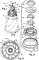
- Fig. 1 is a perspective view, partially cut away, of a blood treating centrifuge including an imperforate bowl and a rotating seal construction embodying the present invention.
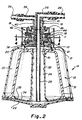
- Fig. 2 is an enlarged cross-section view of the centrifuge bowl, seal and shaft construction taken substantially in the plane of line 2-2 on Fig. 1.
- Fig. 3 is an enlarged portion of the construction shown in Fig. 2 specifically showing the seal construction embodying the present invention.
- Fig. 4 is a section view taken substantially in the plane of line 4-4 on Fig. 2.
- Fig. 5 is a perspective exploded view of the seal construction shown in Fig. 3.
- the present invention is embodied in a supporting plate or hub 10 mounting a rotary seal ring 11 and adapted to be secured to an imperforate outer bowl 12 of a centrifuge 14 suitable for the processing and separation of blood and blood components.
- the centrifuge 14 includes a bowl assembly 15 rotatably mounted on a stationary shaft assembly 16 and utilizing a rotary seal assembly 18 for preventing leakage of the blood and blood components between the rotary bowl assembly 15 and stationary shaft assembly 16.
- the centrifuge assembly 14, as shown in Figs. 1 and 2 embodies a generally bell-shaped outer imperforate bowl 12 having an upper sleeve portion 20 defining an upper opening 21.
- the bottom of the bowl 12 is closed by a bottom plate 22 adapted to be operatively connected to a centrifuge motor (not shown).
- the bowl 12 and bottom plate 22 define a central cavity 24 into which an inlet tube 25 forming a part of the stationary shaft assembly 16 extends.
- the tube opens at the lowermost end of the cavity 24 and at its upper end is provided with an inlet tube 26 connected to an inlet line 28 extending to a pump (not shown) which serves to pump whole blood into the separator bowl.
- a central conical-shaped bowl or core 31 is mounted within the outer shell 12.
- the central core 31 includes a central passage 32 through which the inlet tube 25 extends.
- the central core 31 is provided with a bottom plate 34 positioned adjacent but spaced from the bottom plate 22 to define a separating passage 35 therebetween which opens into the outer circumferential separating chamber 30.
- the separating chamber 30 opens at the upper end of the centrifuge bowl assembly 14 into an outlet chamber 36 defined between the sleeve portion 20 of the outer bowl 12 and the seal ring hub or plate 10.
- a stationary sleeve 40 For exhausting blood components to an outlet conduit 38 connected to an outlet tube 39, a stationary sleeve 40 defines with the inlet tube 25 an annular outlet passage 41.
- the stationary tube 40 and inlet tube 25 define a stationary shaft which is supported on the centrifuge mounting apparatus (not shown).
- the rotating seal assembly 18 For providing a seal between the stationary shaft assembly 16 and the rotating centrifuge bowl assembly 15 the rotating seal assembly 18 includes a stationary seal ring 42 which is rotatingly engaged by the rotary seal ring 11.
- the stationary seal ring 42 is supported in a stationary hub 44 mounted on the shaft assembly 16 and sealed thereto by a flexible diaphragm 45.
- the seal ring mounting hub or plate comprises an annular plate 50 adapted to be secured adjacent its outer peripheral edge to the upstanding sleeve portion 20 of the outer centrifuge housing 12.
- the annular hub plate 50 defines a central shaft receiving opening 51 surrounding the stationary shaft assembly 16.
- the seal ring hub 50 defines an axially extending annular lip 52 adjacent its outer peripheral edge and an intermediate axially extending annular rib 54 parallel and concentric with the lip 52 and being positioned in spaced juxtaposition with the central annular opening 51.
- the rib 54 and upper surface 55 of the annular plate defines a seat for supporting the rotary seal ring 11 in position for rotating engagement with the stationary seal ring 42 secured to the stationary shaft assembly 16.
- a plurality of equally circumferentially spaced chordally arranged vanes 56 are mounted integrally with the mounting plate or hub 50 and extend between the outer lip 52 and the seat defining rib 54. In the modification shown, the vanes overlie the inner annular rib 54 but terminate short of the outer annular lip 52.
- the vanes provide both a cooling effect on the rotary seal as well as a stabilizing effect on the seal ring supporting plate 50 preventing chatter or rattling of the seal rings.
Abstract
The rotary seal, embodying a rotary seal ring (11) and a stationary seal ring (42), for a centrifugal separator (14) including an imperforate bowl (12) has a seal ring hub (10) for supporting the rotary seal ring (11). The seal ring hub (10) is formed by an annular hub plate (50) defining a central shaft receiving opening (51). The plate (50) includes an axially extending annular lip (52) on its periphery and an axially extending annular rib (54) in spaced juxtaposition with the opening (51). A plurality of spaced apart chordally extending vanes (56) extend between the rib (54) and the lip (52) for stabilizing the plate (50) during rotation of the seal and providing a flow of cooling air around the rotary seal.
Description
- The present invention relates to rotary seals for an imperforate bowl centrifuge. More specifically, the present invention relates to a rotary seal for a blood processing centrifuge separator bowl.
- Centrifuge bowls with rotary seals are old and well known in the art of processing blood. In this art, blood is separated into its red cell component and plasma component by a centrifuge utilizing an imperforate bowl which is rotated about a stationary tubular shaft through which whole blood is introduced into the bowl and blood fractions, particularly plasma and red blood cells are sequentially discharged from the bowl. An important part of the centrifuge apparatus is the rotary seal between the stationary shaft and rotating bowl to prevent the leakage of blood components as the bowl rotates.
- U.S. Pat. No. 4,668,214, issued May 26, 1987, to G. Reeder, for Method of Washing Red Blood Cells, discloses a blood processing centrifuge which includes a rotating bowl and a rotary seal between the bowl and a stationary shaft. The rotary seal includes a rotating seal ring mounted in an annular metal plate or hub. The metal plate serves as a heat sink to cool the rotating seal ring. U.S. Pat. No. 4,300,717, issued November 17, 1981, to A. Latham, for Rotary Centrifuge Seal, discloses a centrifuge bowl and a rotary seal between the bowl and a stationary shaft. The rotary seal comprises an upper stationary seal ring supported in a metal adaptor ring secured to the stationary shaft and a lower ceramic rotary seal ring supported in a metallic adaptor ring secured to the rotatable imperforate centrifuge bowl. In order to conduct heat from the seal rings, the patent describes a rotary seal ring construction formed of a good heat conducting material such as metal which conducts heat away from the area of contact between the stationary and rotary rings. The use of ports in an outer shield to dissipate air currents for cooling is described. This patent also discloses the use of vanes on the upper external surface of the imperforate centrifuge bowl for purposes of dissipating heat generated by the seal.
- Some commercial blood pheresis centrifuge bowls and seals utilize a metallic heat sink ring with the seal ring, both of which are supported on a plastic plate or hub secured to the centrifuge bowl.
- The principal problems with the foregoing prior art devices are a lack of efficient cooling, the rotary seal rings tend to chatter, and the supporting hubs utilize expensive metals.
- It is the principal object of the present invention to provide an improved rotary seal for a blood processing centrifuge bowl.
- A more specific object is to provide an improved rotary seal of the foregoing character which is stable, does not chatter or rattle, and which provides an enhanced cooling effect for the rotary seal.
- Another object of the present invention is to provide a rotary seal of the foregoing characteristics which is less expensive than present devices, and is lightweight, rugged, efficient in operation, and maintains a lower operating temperature.
- In accordance with the foregoing objects, the present invention is embodied in an improved seal ring hub for supporting a rotary seal ring of a rotary seal. The rotary seal includes a rotary seal ring and a stationary seal ring for a centrifugal separator which has an imperforate bowl as a part thereof. The seal ring hub comprises an annular hub plate defining a central shaft receiving opening, an axially extending annular lip on its periphery, and an axially extending annular rib in spaced juxtaposition with the annular opening. The rib extends parallel to the lip and defines with the plate a seal ring supporting seat adjacent the opening. A plurality of spaced apart chordally extending vanes extend between the rib and the lip. The vanes extend axially beyond the lip and the rib and terminate adjacent the lip and overlie the rib. The vanes serve to stabilize the plate during rotation of the seal, and provide a flow of cooling air around the rotary seal.
- Fig. 1 is a perspective view, partially cut away, of a blood treating centrifuge including an imperforate bowl and a rotating seal construction embodying the present invention.
- Fig. 2 is an enlarged cross-section view of the centrifuge bowl, seal and shaft construction taken substantially in the plane of line 2-2 on Fig. 1.
- Fig. 3 is an enlarged portion of the construction shown in Fig. 2 specifically showing the seal construction embodying the present invention.
- Fig. 4 is a section view taken substantially in the plane of line 4-4 on Fig. 2.
- Fig. 5 is a perspective exploded view of the seal construction shown in Fig. 3.
- The present invention is embodied in a supporting plate or
hub 10 mounting a rotary seal ring 11 and adapted to be secured to an imperforateouter bowl 12 of acentrifuge 14 suitable for the processing and separation of blood and blood components. Thecentrifuge 14 includes abowl assembly 15 rotatably mounted on astationary shaft assembly 16 and utilizing arotary seal assembly 18 for preventing leakage of the blood and blood components between therotary bowl assembly 15 andstationary shaft assembly 16. - The
centrifuge assembly 14, as shown in Figs. 1 and 2 embodies a generally bell-shaped outerimperforate bowl 12 having anupper sleeve portion 20 defining anupper opening 21. The bottom of thebowl 12 is closed by abottom plate 22 adapted to be operatively connected to a centrifuge motor (not shown). Thebowl 12 andbottom plate 22 define acentral cavity 24 into which aninlet tube 25 forming a part of thestationary shaft assembly 16 extends. The tube opens at the lowermost end of thecavity 24 and at its upper end is provided with aninlet tube 26 connected to aninlet line 28 extending to a pump (not shown) which serves to pump whole blood into the separator bowl. - For forming an outer
circumferential separating chamber 30, a central conical-shaped bowl orcore 31 is mounted within theouter shell 12. Thecentral core 31 includes acentral passage 32 through which theinlet tube 25 extends. Thecentral core 31 is provided with abottom plate 34 positioned adjacent but spaced from thebottom plate 22 to define a separatingpassage 35 therebetween which opens into the outercircumferential separating chamber 30. - For discharge of separated blood components, the
separating chamber 30 opens at the upper end of thecentrifuge bowl assembly 14 into anoutlet chamber 36 defined between thesleeve portion 20 of theouter bowl 12 and the seal ring hub orplate 10. - For exhausting blood components to an
outlet conduit 38 connected to anoutlet tube 39, astationary sleeve 40 defines with theinlet tube 25 anannular outlet passage 41. Thestationary tube 40 andinlet tube 25 define a stationary shaft which is supported on the centrifuge mounting apparatus (not shown). - For providing a seal between the
stationary shaft assembly 16 and the rotatingcentrifuge bowl assembly 15 the rotatingseal assembly 18 includes astationary seal ring 42 which is rotatingly engaged by the rotary seal ring 11. Thestationary seal ring 42 is supported in astationary hub 44 mounted on theshaft assembly 16 and sealed thereto by aflexible diaphragm 45. - Because the contacting faces of the stationary and rotary seal rings respectively generate heat during operation of the centrifuge, the present invention provides an improved heat dissipation and seal ring stabilizing structure. To this end, the seal ring mounting hub or plate comprises an
annular plate 50 adapted to be secured adjacent its outer peripheral edge to theupstanding sleeve portion 20 of theouter centrifuge housing 12. Theannular hub plate 50 defines a central shaft receiving opening 51 surrounding thestationary shaft assembly 16. On its upper surface, theseal ring hub 50 defines an axially extendingannular lip 52 adjacent its outer peripheral edge and an intermediate axially extendingannular rib 54 parallel and concentric with thelip 52 and being positioned in spaced juxtaposition with the centralannular opening 51. Therib 54 andupper surface 55 of the annular plate defines a seat for supporting the rotary seal ring 11 in position for rotating engagement with thestationary seal ring 42 secured to thestationary shaft assembly 16. For purposes of cooling the rotary seal formed by theseal rings 11, 42, a plurality of equally circumferentially spaced chordally arrangedvanes 56 are mounted integrally with the mounting plate orhub 50 and extend between theouter lip 52 and theseat defining rib 54. In the modification shown, the vanes overlie the innerannular rib 54 but terminate short of the outerannular lip 52. - The vanes provide both a cooling effect on the rotary seal as well as a stabilizing effect on the seal
ring supporting plate 50 preventing chatter or rattling of the seal rings. - While a certain illustrative embodiment of the present invention has been shown in the drawings and described above in detail, it should be understood that there is no intention to limit the invention to the specific form disclosed. On the contrary, the intention is to cover all modifications, alternative constructions, equivalents, and uses falling within the spirit and scope of the invention as expressed in the appended claims.
Claims (4)
- In a rotary seal for a centrifugal separator including an imperforate bowl rotatable about a central shaft, said rotary seal embodying a rotary seal ring and a stationary seal ring, a seal ring hub for supporting said rotary seal ring comprising an annular hub plate defining a central shaft receiving opening, an axially extending annular rib on said plate in spaced juxtaposition with said opening, said rib defining with said plate a seal ring supporting seat adjacent said opening, and a plurality of spaced apart vanes extending outwardly from said rib for stabilizing said plate during rotation of said seal and providing a flow of cooling air around said rotary seal.
- In a rotary seal for a centrifugal separator including an imperforate bowl rotatable about a central shaft, said rotary seal embodying a rotary seal ring and a stationary seal ring, a seal ring hub for supporting said rotary seal ring comprising an annular hub plate defining a central shaft receiving opening, an axially extending annular lip on the periphery of said plate, an axially extending annular rib on said plate in spaced juxtaposition with said opening, said rib extending parallel to said lip and defining with said plate a seal ring supporting seat adjacent said opening, and a plurality of spaced apart vanes extending between said rib and said lip for stabilizing said plate during rotation of said seal and providing a flow of cooling air around said rotary seal.
- In a rotary seal ring of a rotary seal for a centrifugal separator including an imperforate bowl rotatable about a central shaft, said rotary seal embodying a rotary seal ring and a stationary seal ring, a seal ring hub for supporting said rotary seal ring comprising an annular hub plate defining a central shaft receiving opening, an axially extending annular lip on the periphery of said plate, an axially extending annular rib on said plate in spaced juxtaposition with said opening, said rib extending parallel to said lip and defining with said plate a seal ring supporting seat adjacent said opening, and a plurality of spaced apart chordal vanes extending between said rib and said lip, said vanes extending axially beyond said lip and said rib for stabilizing said plate during rotation of said seal and providing a flow of cooling air around said rotary seal.
- In a rotary seal for a centrifugal separator including an imperforate bowl rotatable about a central stationary shaft, said rotary seal embodying a rotary seal ring and a stationary seal ring, a seal ring hub for supporting said rotary seal ring comprising an annular hub plate defining a central shaft receiving opening, an axially extending annular lip on the periphery of said plate, an axially extending annular rib on said plate in spaced juxtaposition with said opening, said rib extending parallel to said lip and defining with said plate a seal ring supporting seat adjacent said opening, and a plurality of spaced apart chordal vanes extending between said rib and said lip, said vanes extending axially beyond said lip and said rib and terminating adjacent said lip and overlying said rib for stabilizing said plate during rotation of said seal and providing a flow of cooling air around said rotary seal.
Applications Claiming Priority (2)
| Application Number | Priority Date | Filing Date | Title |
|---|---|---|---|
| US4343693A | 1993-04-05 | 1993-04-05 | |
| US43436 | 1993-04-05 |
Publications (2)
| Publication Number | Publication Date |
|---|---|
| EP0619145A2 true EP0619145A2 (en) | 1994-10-12 |
| EP0619145A3 EP0619145A3 (en) | 1995-04-05 |
Family
ID=21927161
Family Applications (1)
| Application Number | Title | Priority Date | Filing Date |
|---|---|---|---|
| EP94630019A Withdrawn EP0619145A3 (en) | 1993-04-05 | 1994-03-31 | Rotary seal for centrifuge. |
Country Status (2)
| Country | Link |
|---|---|
| EP (1) | EP0619145A3 (en) |
| JP (1) | JPH0775746A (en) |
Cited By (22)
| Publication number | Priority date | Publication date | Assignee | Title |
|---|---|---|---|---|
| WO1998008611A1 (en) | 1996-08-26 | 1998-03-05 | Aribert Komanns | Sorting centrifuging system |
| US5919125A (en) * | 1997-07-11 | 1999-07-06 | Cobe Laboratories, Inc. | Centrifuge bowl for autologous blood salvage |
| US5976388A (en) * | 1997-05-20 | 1999-11-02 | Cobe Cardiovascular Operating Co., Inc. | Method and apparatus for autologous blood salvage |
| US6464624B2 (en) * | 1999-06-03 | 2002-10-15 | Haemonetics Corporation | Blood processing method and apparatus using a centrifugation bowl with filter core |
| US6475132B2 (en) | 2000-06-16 | 2002-11-05 | Westfalia Separator Food Tec Gmbh | Double-intake disk centrifuge |
| US6629919B2 (en) * | 1999-06-03 | 2003-10-07 | Haemonetics Corporation | Core for blood processing apparatus |
| WO2007071086A1 (en) | 2005-12-21 | 2007-06-28 | Jean-Denis Rochat | Disposable device for centrifugation of blood |
| CN103008117A (en) * | 2012-12-05 | 2013-04-03 | 大连优力特换热设备制造有限公司 | Liquid phase separating machine |
| US8454548B2 (en) | 2008-04-14 | 2013-06-04 | Haemonetics Corporation | System and method for plasma reduced platelet collection |
| US8628489B2 (en) | 2008-04-14 | 2014-01-14 | Haemonetics Corporation | Three-line apheresis system and method |
| US8647289B2 (en) | 2008-04-14 | 2014-02-11 | Haemonetics Corporation | System and method for optimized apheresis draw and return |
| US8753079B2 (en) | 2009-03-16 | 2014-06-17 | Vulco S.A. | Mechanical seal |
| US8808978B2 (en) | 2010-11-05 | 2014-08-19 | Haemonetics Corporation | System and method for automated platelet wash |
| US8834402B2 (en) | 2009-03-12 | 2014-09-16 | Haemonetics Corporation | System and method for the re-anticoagulation of platelet rich plasma |
| US10758652B2 (en) | 2017-05-30 | 2020-09-01 | Haemonetics Corporation | System and method for collecting plasma |
| US10792416B2 (en) | 2017-05-30 | 2020-10-06 | Haemonetics Corporation | System and method for collecting plasma |
| US10806847B2 (en) | 2010-12-30 | 2020-10-20 | Haemonetics Corporation | System and method for collecting platelets and anticipating plasma return |
| US10946131B2 (en) | 2018-05-21 | 2021-03-16 | Fenwal, Inc. | Systems and methods for optimization of plasma collection volumes |
| US11065376B2 (en) | 2018-03-26 | 2021-07-20 | Haemonetics Corporation | Plasmapheresis centrifuge bowl |
| US11325136B2 (en) | 2017-04-07 | 2022-05-10 | Alfa Laval Corporate Ab | Seal assembly for a centrifugal separator |
| US11412967B2 (en) | 2018-05-21 | 2022-08-16 | Fenwal, Inc. | Systems and methods for plasma collection |
| US11837357B2 (en) | 2011-05-18 | 2023-12-05 | Fenwal, Inc. | Plasma collection with remote programming |
Families Citing this family (2)
| Publication number | Priority date | Publication date | Assignee | Title |
|---|---|---|---|---|
| US7479123B2 (en) | 2002-03-04 | 2009-01-20 | Therakos, Inc. | Method for collecting a desired blood component and performing a photopheresis treatment |
| KR101530565B1 (en) * | 2013-08-12 | 2015-06-22 | 이현근 | Casing assembly for centrifugal machine |
Citations (3)
| Publication number | Priority date | Publication date | Assignee | Title |
|---|---|---|---|---|
| US4300717A (en) * | 1979-04-02 | 1981-11-17 | Haemonetics Corporation | Rotary centrifuge seal |
| EP0285891A2 (en) * | 1987-04-08 | 1988-10-12 | DIDECO S.p.A. | Blood centrifugation cell |
| US5045048A (en) * | 1990-03-29 | 1991-09-03 | Haemonetics Corporation | Rotary centrifuge bowl and seal for blood processing |
-
1993
- 1993-12-24 JP JP32806593A patent/JPH0775746A/en active Pending
-
1994
- 1994-03-31 EP EP94630019A patent/EP0619145A3/en not_active Withdrawn
Patent Citations (3)
| Publication number | Priority date | Publication date | Assignee | Title |
|---|---|---|---|---|
| US4300717A (en) * | 1979-04-02 | 1981-11-17 | Haemonetics Corporation | Rotary centrifuge seal |
| EP0285891A2 (en) * | 1987-04-08 | 1988-10-12 | DIDECO S.p.A. | Blood centrifugation cell |
| US5045048A (en) * | 1990-03-29 | 1991-09-03 | Haemonetics Corporation | Rotary centrifuge bowl and seal for blood processing |
Cited By (44)
| Publication number | Priority date | Publication date | Assignee | Title |
|---|---|---|---|---|
| WO1998008611A1 (en) | 1996-08-26 | 1998-03-05 | Aribert Komanns | Sorting centrifuging system |
| DE19634413A1 (en) * | 1996-08-26 | 1998-03-12 | Komanns Aribert | Method and device for sorting centrifugation or sorting flow centrifugation |
| DE19634413C2 (en) * | 1996-08-26 | 1998-07-30 | Komanns Aribert | Sorting centrifugation or sorting flow centrifugation method and apparatus for carrying out the method |
| US5976388A (en) * | 1997-05-20 | 1999-11-02 | Cobe Cardiovascular Operating Co., Inc. | Method and apparatus for autologous blood salvage |
| US5919125A (en) * | 1997-07-11 | 1999-07-06 | Cobe Laboratories, Inc. | Centrifuge bowl for autologous blood salvage |
| US6464624B2 (en) * | 1999-06-03 | 2002-10-15 | Haemonetics Corporation | Blood processing method and apparatus using a centrifugation bowl with filter core |
| US6629919B2 (en) * | 1999-06-03 | 2003-10-07 | Haemonetics Corporation | Core for blood processing apparatus |
| US6475132B2 (en) | 2000-06-16 | 2002-11-05 | Westfalia Separator Food Tec Gmbh | Double-intake disk centrifuge |
| WO2007071086A1 (en) | 2005-12-21 | 2007-06-28 | Jean-Denis Rochat | Disposable device for centrifugation of blood |
| US9364600B2 (en) | 2008-04-14 | 2016-06-14 | Haemonetics Corporation | System and method for optimized apheresis draw and return |
| US8628489B2 (en) | 2008-04-14 | 2014-01-14 | Haemonetics Corporation | Three-line apheresis system and method |
| US8647289B2 (en) | 2008-04-14 | 2014-02-11 | Haemonetics Corporation | System and method for optimized apheresis draw and return |
| US8702637B2 (en) | 2008-04-14 | 2014-04-22 | Haemonetics Corporation | System and method for optimized apheresis draw and return |
| US8454548B2 (en) | 2008-04-14 | 2013-06-04 | Haemonetics Corporation | System and method for plasma reduced platelet collection |
| US8808217B2 (en) | 2008-04-14 | 2014-08-19 | Haemonetics Corporation | System and method for plasma reduced platelet collection |
| US9095665B2 (en) | 2008-04-14 | 2015-08-04 | Haemonetics Corporation | Three-line apheresis system and method |
| US9248227B2 (en) | 2009-03-12 | 2016-02-02 | Haemonetics Corporation | System and method for the re-anticoagulation of platelet rich plasma |
| US9789243B2 (en) | 2009-03-12 | 2017-10-17 | Haemonetics Corporation | System and method for the re-anticoagulation of platelet rich plasma |
| US8834402B2 (en) | 2009-03-12 | 2014-09-16 | Haemonetics Corporation | System and method for the re-anticoagulation of platelet rich plasma |
| US8753079B2 (en) | 2009-03-16 | 2014-06-17 | Vulco S.A. | Mechanical seal |
| US9249885B2 (en) | 2009-03-16 | 2016-02-02 | Vulco, S. A. | Mechanical seal with improved seal assembly |
| US9206906B2 (en) | 2009-03-16 | 2015-12-08 | Vulco, S.A. | Adjustable mechanical seal |
| US9593777B2 (en) | 2009-03-16 | 2017-03-14 | Vulco S.A. | Mechanical seal |
| US8808978B2 (en) | 2010-11-05 | 2014-08-19 | Haemonetics Corporation | System and method for automated platelet wash |
| US9833794B2 (en) | 2010-11-05 | 2017-12-05 | Haemonetics Corporation | System and method for automated platelet wash |
| US10806847B2 (en) | 2010-12-30 | 2020-10-20 | Haemonetics Corporation | System and method for collecting platelets and anticipating plasma return |
| US11837357B2 (en) | 2011-05-18 | 2023-12-05 | Fenwal, Inc. | Plasma collection with remote programming |
| CN103008117A (en) * | 2012-12-05 | 2013-04-03 | 大连优力特换热设备制造有限公司 | Liquid phase separating machine |
| US11325136B2 (en) | 2017-04-07 | 2022-05-10 | Alfa Laval Corporate Ab | Seal assembly for a centrifugal separator |
| US10758652B2 (en) | 2017-05-30 | 2020-09-01 | Haemonetics Corporation | System and method for collecting plasma |
| US10980934B2 (en) | 2017-05-30 | 2021-04-20 | Haemonetics Corporation | System and method for collecting plasma |
| US10980926B2 (en) | 2017-05-30 | 2021-04-20 | Haemonetics Corporation | System and method for collecting plasma |
| US10792416B2 (en) | 2017-05-30 | 2020-10-06 | Haemonetics Corporation | System and method for collecting plasma |
| US11738124B2 (en) | 2017-05-30 | 2023-08-29 | Haemonetics Corporation | System and method for collecting plasma |
| US11065376B2 (en) | 2018-03-26 | 2021-07-20 | Haemonetics Corporation | Plasmapheresis centrifuge bowl |
| US10946131B2 (en) | 2018-05-21 | 2021-03-16 | Fenwal, Inc. | Systems and methods for optimization of plasma collection volumes |
| US11285251B2 (en) | 2018-05-21 | 2022-03-29 | Fenwal, Inc. | Systems and methods for optimization of plasma collection volumes |
| US11369724B2 (en) | 2018-05-21 | 2022-06-28 | Fenwal, Inc. | Systems and methods for optimization of plasma collection volumes |
| US11383013B2 (en) | 2018-05-21 | 2022-07-12 | Fenwal, Inc. | Systems and methods for optimization of plasma collection volumes |
| US11412967B2 (en) | 2018-05-21 | 2022-08-16 | Fenwal, Inc. | Systems and methods for plasma collection |
| US11730873B2 (en) | 2018-05-21 | 2023-08-22 | Fenwal, Inc. | Systems and methods for optimization of plasma collection volumes |
| US11110216B2 (en) | 2018-05-21 | 2021-09-07 | Fenwal, Inc. | Systems and methods for optimization of plasma collection volumes |
| US11801001B2 (en) | 2018-05-21 | 2023-10-31 | Fenwal, Inc. | Systems and methods for plasma collection |
| US11097042B2 (en) | 2018-05-21 | 2021-08-24 | Fenwal, Inc. | Systems and methods for optimization of plasma collection volumes |
Also Published As
| Publication number | Publication date |
|---|---|
| EP0619145A3 (en) | 1995-04-05 |
| JPH0775746A (en) | 1995-03-20 |
Similar Documents
| Publication | Publication Date | Title |
|---|---|---|
| EP0619145A2 (en) | Rotary seal for centrifuge | |
| US4693734A (en) | Vacuum cleaner construction | |
| CA2663531C (en) | Separator drum and compressor impeller assembly | |
| JP3357371B2 (en) | centrifuge | |
| AU605042B2 (en) | Shrouding for engine cooling fan | |
| GB2181042A (en) | Vacuum cleaner | |
| EP1050682A2 (en) | A motor-driven fan, particularly for a motor vehicle heat exchanger | |
| CA1266077A (en) | Motor cooling fan housing | |
| US10493468B2 (en) | Centrifugal separator for cleaning gas | |
| KR970706903A (en) | CENTRIFUGAL SEPARATOR | |
| CN105307821B (en) | Electric tool | |
| US5537988A (en) | Grease guiding tray for a kitchen ventilator | |
| CA1302025C (en) | Radial cooling fan for vacuum cleaner motor | |
| EP0804291B1 (en) | Rotor for centrifugal separator with sound damping radial openings | |
| JPH11236820A (en) | Manually operated working machine | |
| JP4382992B2 (en) | Reaction-driven centrifugal rotor | |
| KR970005861B1 (en) | Vane opening recycle turbine pump | |
| CN114586262B (en) | Cooling liquid passage structure of motor | |
| CA2590090A1 (en) | Multi-stage taper fan-motor assembly | |
| EP0703829B1 (en) | Centrifugal separator | |
| JP2003112065A (en) | Wet media stirring mill | |
| JPH03500380A (en) | Centrifuge with discharge device | |
| US4818193A (en) | Centrifugal pump selectively mountable in centerline or inline position | |
| US20080206050A1 (en) | Dual taper fan-motor assembly | |
| JP2003275621A (en) | Air cooling type centrifugal separator |
Legal Events
| Date | Code | Title | Description |
|---|---|---|---|
| PUAI | Public reference made under article 153(3) epc to a published international application that has entered the european phase |
Free format text: ORIGINAL CODE: 0009012 |
|
| AK | Designated contracting states |
Kind code of ref document: A2 Designated state(s): DE FR IT |
|
| PUAL | Search report despatched |
Free format text: ORIGINAL CODE: 0009013 |
|
| AK | Designated contracting states |
Kind code of ref document: A3 Designated state(s): DE FR IT |
|
| STAA | Information on the status of an ep patent application or granted ep patent |
Free format text: STATUS: THE APPLICATION IS DEEMED TO BE WITHDRAWN |
|
| 18D | Application deemed to be withdrawn |
Effective date: 19950818 |