EP0619175A2 - Sterile containment welding device for plastic tubes - Google Patents
Sterile containment welding device for plastic tubes Download PDFInfo
- Publication number
- EP0619175A2 EP0619175A2 EP94101709A EP94101709A EP0619175A2 EP 0619175 A2 EP0619175 A2 EP 0619175A2 EP 94101709 A EP94101709 A EP 94101709A EP 94101709 A EP94101709 A EP 94101709A EP 0619175 A2 EP0619175 A2 EP 0619175A2
- Authority
- EP
- European Patent Office
- Prior art keywords
- tube
- tubes
- holders
- lid
- plastic
- Prior art date
- Legal status (The legal status is an assumption and is not a legal conclusion. Google has not performed a legal analysis and makes no representation as to the accuracy of the status listed.)
- Withdrawn
Links
Images


Classifications
-
- B—PERFORMING OPERATIONS; TRANSPORTING
- B29—WORKING OF PLASTICS; WORKING OF SUBSTANCES IN A PLASTIC STATE IN GENERAL
- B29C—SHAPING OR JOINING OF PLASTICS; SHAPING OF MATERIAL IN A PLASTIC STATE, NOT OTHERWISE PROVIDED FOR; AFTER-TREATMENT OF THE SHAPED PRODUCTS, e.g. REPAIRING
- B29C65/00—Joining or sealing of preformed parts, e.g. welding of plastics materials; Apparatus therefor
- B29C65/78—Means for handling the parts to be joined, e.g. for making containers or hollow articles, e.g. means for handling sheets, plates, web-like materials, tubular articles, hollow articles or elements to be joined therewith; Means for discharging the joined articles from the joining apparatus
- B29C65/7802—Positioning the parts to be joined, e.g. aligning, indexing or centring
-
- B—PERFORMING OPERATIONS; TRANSPORTING
- B29—WORKING OF PLASTICS; WORKING OF SUBSTANCES IN A PLASTIC STATE IN GENERAL
- B29C—SHAPING OR JOINING OF PLASTICS; SHAPING OF MATERIAL IN A PLASTIC STATE, NOT OTHERWISE PROVIDED FOR; AFTER-TREATMENT OF THE SHAPED PRODUCTS, e.g. REPAIRING
- B29C65/00—Joining or sealing of preformed parts, e.g. welding of plastics materials; Apparatus therefor
- B29C65/02—Joining or sealing of preformed parts, e.g. welding of plastics materials; Apparatus therefor by heating, with or without pressure
- B29C65/18—Joining or sealing of preformed parts, e.g. welding of plastics materials; Apparatus therefor by heating, with or without pressure using heated tools
- B29C65/20—Joining or sealing of preformed parts, e.g. welding of plastics materials; Apparatus therefor by heating, with or without pressure using heated tools with direct contact, e.g. using "mirror"
- B29C65/2046—Joining or sealing of preformed parts, e.g. welding of plastics materials; Apparatus therefor by heating, with or without pressure using heated tools with direct contact, e.g. using "mirror" using a welding mirror which also cuts the parts to be joined, e.g. for sterile welding
-
- B—PERFORMING OPERATIONS; TRANSPORTING
- B29—WORKING OF PLASTICS; WORKING OF SUBSTANCES IN A PLASTIC STATE IN GENERAL
- B29C—SHAPING OR JOINING OF PLASTICS; SHAPING OF MATERIAL IN A PLASTIC STATE, NOT OTHERWISE PROVIDED FOR; AFTER-TREATMENT OF THE SHAPED PRODUCTS, e.g. REPAIRING
- B29C65/00—Joining or sealing of preformed parts, e.g. welding of plastics materials; Apparatus therefor
- B29C65/02—Joining or sealing of preformed parts, e.g. welding of plastics materials; Apparatus therefor by heating, with or without pressure
- B29C65/18—Joining or sealing of preformed parts, e.g. welding of plastics materials; Apparatus therefor by heating, with or without pressure using heated tools
- B29C65/20—Joining or sealing of preformed parts, e.g. welding of plastics materials; Apparatus therefor by heating, with or without pressure using heated tools with direct contact, e.g. using "mirror"
- B29C65/2053—Joining or sealing of preformed parts, e.g. welding of plastics materials; Apparatus therefor by heating, with or without pressure using heated tools with direct contact, e.g. using "mirror" characterised by special ways of bringing the welding mirrors into position
- B29C65/2061—Joining or sealing of preformed parts, e.g. welding of plastics materials; Apparatus therefor by heating, with or without pressure using heated tools with direct contact, e.g. using "mirror" characterised by special ways of bringing the welding mirrors into position by sliding
-
- B—PERFORMING OPERATIONS; TRANSPORTING
- B29—WORKING OF PLASTICS; WORKING OF SUBSTANCES IN A PLASTIC STATE IN GENERAL
- B29C—SHAPING OR JOINING OF PLASTICS; SHAPING OF MATERIAL IN A PLASTIC STATE, NOT OTHERWISE PROVIDED FOR; AFTER-TREATMENT OF THE SHAPED PRODUCTS, e.g. REPAIRING
- B29C65/00—Joining or sealing of preformed parts, e.g. welding of plastics materials; Apparatus therefor
- B29C65/78—Means for handling the parts to be joined, e.g. for making containers or hollow articles, e.g. means for handling sheets, plates, web-like materials, tubular articles, hollow articles or elements to be joined therewith; Means for discharging the joined articles from the joining apparatus
- B29C65/7841—Holding or clamping means for handling purposes
-
- B—PERFORMING OPERATIONS; TRANSPORTING
- B29—WORKING OF PLASTICS; WORKING OF SUBSTANCES IN A PLASTIC STATE IN GENERAL
- B29C—SHAPING OR JOINING OF PLASTICS; SHAPING OF MATERIAL IN A PLASTIC STATE, NOT OTHERWISE PROVIDED FOR; AFTER-TREATMENT OF THE SHAPED PRODUCTS, e.g. REPAIRING
- B29C66/00—General aspects of processes or apparatus for joining preformed parts
- B29C66/001—Joining in special atmospheres
- B29C66/0012—Joining in special atmospheres characterised by the type of environment
- B29C66/0018—Joining in special atmospheres characterised by the type of environment being sterile
-
- B—PERFORMING OPERATIONS; TRANSPORTING
- B29—WORKING OF PLASTICS; WORKING OF SUBSTANCES IN A PLASTIC STATE IN GENERAL
- B29C—SHAPING OR JOINING OF PLASTICS; SHAPING OF MATERIAL IN A PLASTIC STATE, NOT OTHERWISE PROVIDED FOR; AFTER-TREATMENT OF THE SHAPED PRODUCTS, e.g. REPAIRING
- B29C66/00—General aspects of processes or apparatus for joining preformed parts
- B29C66/01—General aspects dealing with the joint area or with the area to be joined
- B29C66/05—Particular design of joint configurations
- B29C66/10—Particular design of joint configurations particular design of the joint cross-sections
- B29C66/11—Joint cross-sections comprising a single joint-segment, i.e. one of the parts to be joined comprising a single joint-segment in the joint cross-section
- B29C66/114—Single butt joints
- B29C66/1142—Single butt to butt joints
-
- B—PERFORMING OPERATIONS; TRANSPORTING
- B29—WORKING OF PLASTICS; WORKING OF SUBSTANCES IN A PLASTIC STATE IN GENERAL
- B29C—SHAPING OR JOINING OF PLASTICS; SHAPING OF MATERIAL IN A PLASTIC STATE, NOT OTHERWISE PROVIDED FOR; AFTER-TREATMENT OF THE SHAPED PRODUCTS, e.g. REPAIRING
- B29C66/00—General aspects of processes or apparatus for joining preformed parts
- B29C66/50—General aspects of joining tubular articles; General aspects of joining long products, i.e. bars or profiled elements; General aspects of joining single elements to tubular articles, hollow articles or bars; General aspects of joining several hollow-preforms to form hollow or tubular articles
- B29C66/51—Joining tubular articles, profiled elements or bars; Joining single elements to tubular articles, hollow articles or bars; Joining several hollow-preforms to form hollow or tubular articles
- B29C66/52—Joining tubular articles, bars or profiled elements
- B29C66/522—Joining tubular articles
- B29C66/5221—Joining tubular articles for forming coaxial connections, i.e. the tubular articles to be joined forming a zero angle relative to each other
-
- B—PERFORMING OPERATIONS; TRANSPORTING
- B29—WORKING OF PLASTICS; WORKING OF SUBSTANCES IN A PLASTIC STATE IN GENERAL
- B29C—SHAPING OR JOINING OF PLASTICS; SHAPING OF MATERIAL IN A PLASTIC STATE, NOT OTHERWISE PROVIDED FOR; AFTER-TREATMENT OF THE SHAPED PRODUCTS, e.g. REPAIRING
- B29C66/00—General aspects of processes or apparatus for joining preformed parts
- B29C66/70—General aspects of processes or apparatus for joining preformed parts characterised by the composition, physical properties or the structure of the material of the parts to be joined; Joining with non-plastics material
- B29C66/73—General aspects of processes or apparatus for joining preformed parts characterised by the composition, physical properties or the structure of the material of the parts to be joined; Joining with non-plastics material characterised by the intensive physical properties of the material of the parts to be joined, by the optical properties of the material of the parts to be joined, by the extensive physical properties of the parts to be joined, by the state of the material of the parts to be joined or by the material of the parts to be joined being a thermoplastic or a thermoset
- B29C66/739—General aspects of processes or apparatus for joining preformed parts characterised by the composition, physical properties or the structure of the material of the parts to be joined; Joining with non-plastics material characterised by the intensive physical properties of the material of the parts to be joined, by the optical properties of the material of the parts to be joined, by the extensive physical properties of the parts to be joined, by the state of the material of the parts to be joined or by the material of the parts to be joined being a thermoplastic or a thermoset characterised by the material of the parts to be joined being a thermoplastic or a thermoset
- B29C66/7392—General aspects of processes or apparatus for joining preformed parts characterised by the composition, physical properties or the structure of the material of the parts to be joined; Joining with non-plastics material characterised by the intensive physical properties of the material of the parts to be joined, by the optical properties of the material of the parts to be joined, by the extensive physical properties of the parts to be joined, by the state of the material of the parts to be joined or by the material of the parts to be joined being a thermoplastic or a thermoset characterised by the material of the parts to be joined being a thermoplastic or a thermoset characterised by the material of at least one of the parts being a thermoplastic
- B29C66/73921—General aspects of processes or apparatus for joining preformed parts characterised by the composition, physical properties or the structure of the material of the parts to be joined; Joining with non-plastics material characterised by the intensive physical properties of the material of the parts to be joined, by the optical properties of the material of the parts to be joined, by the extensive physical properties of the parts to be joined, by the state of the material of the parts to be joined or by the material of the parts to be joined being a thermoplastic or a thermoset characterised by the material of the parts to be joined being a thermoplastic or a thermoset characterised by the material of at least one of the parts being a thermoplastic characterised by the materials of both parts being thermoplastics
-
- B—PERFORMING OPERATIONS; TRANSPORTING
- B29—WORKING OF PLASTICS; WORKING OF SUBSTANCES IN A PLASTIC STATE IN GENERAL
- B29L—INDEXING SCHEME ASSOCIATED WITH SUBCLASS B29C, RELATING TO PARTICULAR ARTICLES
- B29L2023/00—Tubular articles
- B29L2023/005—Hoses, i.e. flexible
- B29L2023/006—Flexible liners
-
- B—PERFORMING OPERATIONS; TRANSPORTING
- B29—WORKING OF PLASTICS; WORKING OF SUBSTANCES IN A PLASTIC STATE IN GENERAL
- B29L—INDEXING SCHEME ASSOCIATED WITH SUBCLASS B29C, RELATING TO PARTICULAR ARTICLES
- B29L2023/00—Tubular articles
- B29L2023/22—Tubes or pipes, i.e. rigid
-
- Y—GENERAL TAGGING OF NEW TECHNOLOGICAL DEVELOPMENTS; GENERAL TAGGING OF CROSS-SECTIONAL TECHNOLOGIES SPANNING OVER SEVERAL SECTIONS OF THE IPC; TECHNICAL SUBJECTS COVERED BY FORMER USPC CROSS-REFERENCE ART COLLECTIONS [XRACs] AND DIGESTS
- Y10—TECHNICAL SUBJECTS COVERED BY FORMER USPC
- Y10T—TECHNICAL SUBJECTS COVERED BY FORMER US CLASSIFICATION
- Y10T156/00—Adhesive bonding and miscellaneous chemical manufacture
- Y10T156/10—Methods of surface bonding and/or assembly therefor
- Y10T156/1052—Methods of surface bonding and/or assembly therefor with cutting, punching, tearing or severing
- Y10T156/1054—Methods of surface bonding and/or assembly therefor with cutting, punching, tearing or severing and simultaneously bonding [e.g., cut-seaming]
-
- Y—GENERAL TAGGING OF NEW TECHNOLOGICAL DEVELOPMENTS; GENERAL TAGGING OF CROSS-SECTIONAL TECHNOLOGIES SPANNING OVER SEVERAL SECTIONS OF THE IPC; TECHNICAL SUBJECTS COVERED BY FORMER USPC CROSS-REFERENCE ART COLLECTIONS [XRACs] AND DIGESTS
- Y10—TECHNICAL SUBJECTS COVERED BY FORMER USPC
- Y10T—TECHNICAL SUBJECTS COVERED BY FORMER US CLASSIFICATION
- Y10T156/00—Adhesive bonding and miscellaneous chemical manufacture
- Y10T156/10—Methods of surface bonding and/or assembly therefor
- Y10T156/1052—Methods of surface bonding and/or assembly therefor with cutting, punching, tearing or severing
- Y10T156/1062—Prior to assembly
- Y10T156/1066—Cutting to shape joining edge surfaces only
-
- Y—GENERAL TAGGING OF NEW TECHNOLOGICAL DEVELOPMENTS; GENERAL TAGGING OF CROSS-SECTIONAL TECHNOLOGIES SPANNING OVER SEVERAL SECTIONS OF THE IPC; TECHNICAL SUBJECTS COVERED BY FORMER USPC CROSS-REFERENCE ART COLLECTIONS [XRACs] AND DIGESTS
- Y10—TECHNICAL SUBJECTS COVERED BY FORMER USPC
- Y10T—TECHNICAL SUBJECTS COVERED BY FORMER US CLASSIFICATION
- Y10T156/00—Adhesive bonding and miscellaneous chemical manufacture
- Y10T156/12—Surface bonding means and/or assembly means with cutting, punching, piercing, severing or tearing
- Y10T156/1313—Cutting element simultaneously bonds [e.g., cut seaming]
-
- Y—GENERAL TAGGING OF NEW TECHNOLOGICAL DEVELOPMENTS; GENERAL TAGGING OF CROSS-SECTIONAL TECHNOLOGIES SPANNING OVER SEVERAL SECTIONS OF THE IPC; TECHNICAL SUBJECTS COVERED BY FORMER USPC CROSS-REFERENCE ART COLLECTIONS [XRACs] AND DIGESTS
- Y10—TECHNICAL SUBJECTS COVERED BY FORMER USPC
- Y10T—TECHNICAL SUBJECTS COVERED BY FORMER US CLASSIFICATION
- Y10T156/00—Adhesive bonding and miscellaneous chemical manufacture
- Y10T156/12—Surface bonding means and/or assembly means with cutting, punching, piercing, severing or tearing
- Y10T156/1317—Means feeding plural workpieces to be joined
- Y10T156/1322—Severing before bonding or assembling of parts
- Y10T156/1326—Severing means or member secured thereto also bonds
-
- Y—GENERAL TAGGING OF NEW TECHNOLOGICAL DEVELOPMENTS; GENERAL TAGGING OF CROSS-SECTIONAL TECHNOLOGIES SPANNING OVER SEVERAL SECTIONS OF THE IPC; TECHNICAL SUBJECTS COVERED BY FORMER USPC CROSS-REFERENCE ART COLLECTIONS [XRACs] AND DIGESTS
- Y10—TECHNICAL SUBJECTS COVERED BY FORMER USPC
- Y10T—TECHNICAL SUBJECTS COVERED BY FORMER US CLASSIFICATION
- Y10T156/00—Adhesive bonding and miscellaneous chemical manufacture
- Y10T156/12—Surface bonding means and/or assembly means with cutting, punching, piercing, severing or tearing
- Y10T156/1378—Cutter actuated by or secured to bonding element
Definitions
- U.S. Patent 4,753,697 discloses an arrangement in Figure 3 wherein an aligning bar 24 is suspended from a rail 26 so that the aligning bar could be located in the space between the tube holders and so that the tubes could be moved forward into contact with the aligning bar.
- the aligning bar would form a means of locating the tubes with respect to each other. After this locating step is performed, the aligning bar is moved out of its position of contact with the tubes.
- Parent application Serial No. 965,875 discloses a total containment device for the con- nect/disconnect of plastic tubes. That device includes movable wall mounted to each clamp base. The wall serves as a locator for properly positioning a tube in its associated clamp base. Each base includes a clamp lid which has an inactivating member so that upon movement of the lid to its closing position the wall is automatically moved out of contact with its tube to expose the tubes for the later heating and welding steps.
- This arrangement has the advantage of automatically removing the movable wall away from the tubes upon the closing of the lid and does not rely upon other operations, such as would be required to move the aligning bar out of contact with the tubes as in U.S. Patent 4,753,697.
- the present invention is directed to these aspects of parent application Serial No. 965,875.
- An object of this invention is to provide a sterile containment welding device which includes some means for properly positioning the plastic tubes for the later heating and welding steps.
- a further object of this invention is to provide such a device which utilizes features disclosed in parent application Serial No. 965,875 for automatically removing the locating member after the tubes have been properly positioned.
- a still further object of this invention is to provide such a device which can be used for properly positioning fluid filled tubes, particularly tubes mounted in a bent condition.
- a sterile containment welding device for plastic tubes comprises a pair of side by side spaced tube holders.
- Each of the tube holders includes a clamp base and a clamp lid with a pocket extending completely across the clamp base so that a plastic tube may be inserted in the pocket and clamped in the holder when the clamp lid is moved to its closed position.
- the pockets of the side by side tube holders are alignable with each other to permit a plastic tube in one of the holders to be welded to a plastic tube in the other holder after the tubes have been heated.
- a tube locating member is mounted at the end of each pocket in the space between the holders.
- Each tube locating member has a wall located in the space between the holders with the wall disposed beyond and across its pocket for positioning a plastic tube in its proper location during the later welding step. This is accomplished by moving the tube into contact with the wall.
- An inactivating member is mounted to its lid and is movable into contact with its tube locating member for moving the tube locating member out of contact with the plastic tube upon the closing of the lid to expose the tubes and permit them to be later heated and welded together.
- the invention may be practiced by utilizing a spring to bias the tube locating member in its positioning orientation.
- the tube locating member may be U-shaped with the bight of the U being the locating wall and with the legs of the U having holes into which pivot pins are inserted to permit the tube locating member to be pivoted out of contact with the tube upon the closing of the lid.
- Figure 1 illustrates a sterile containment welding device 10 in accordance with this invention.
- Device 10 is generally of the structure of the device illustrated and described in parent application Serial No. 965,875 the details of which are incorporated herein by reference thereto. Accordingly, device 10 will be described only with respect to those details as is necessary for an understanding of the present invention.
- device 10 includes a pair of side by side spaced tube holders 12,12.
- Each of the tube holders includes a clamp base 14 and a clamp lid 16 pivotally connected to the clamp base.
- a pocket or groove 18 extends completely across each clamp base so that a plastic tube T may be inserted in the pocket and clamped to its holder when clamp lid 16 is pivoted to its closed position.
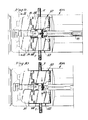
- Figure 1 illustrates one of the clamp holders with its lid 16 in the open position at the upper portion of Figure 1 while the lower portion of Figure 1 illustrates the clamp holder with the lid 16 in its closed clamping position.
- Figures 2-3 show the lid 16 open and
- Figures 4-5 show the lid closed.
- the clamp holders 12,12 are mounted spaced from each other. As described in the parent application, the clamp holders can be moved toward and away from each other to change the spacing. Initially, the spacing would be greater when the tubes T,T are inserted into each clamp holder. It is essential that the tubes be properly positioned in the clamp holders so that when the clamp holders are then pivoted toward each other the tubes are properly aligned and spaced for the later heating and welding operations.
- the present invention incorporates a tube locating member 20 mounted to each clamp base 14 at the end of each pocket 18 in the spacing between the tube holders.
- FIG 8 illustrates a tube locating member 20.
- tube locating member 20 is generally U-shaped with the bight of the U being a flat wall 22 and with a pair of legs 24 extending outwardly from wall 22.
- the inner surface of tube locating member 20 has an inwardly directed shoulder 26 at the junction of each leg 24 with the bight or wall 22. This creates a recess at the inner surface of wall 22 which would be dimensioned to receive a tube T.
- the shoulders 26 would provide some clearance to accommodate the plastic tube T as it is pressed into the recess at the inner surface of locating wall 22.
- each leg 24 is provided with a hole 28 extending completely through the leg.
- the clamp base 14 includes a cut-away portion 30 which would accommodate tube locating member 20 when the tube locating member 20 is rotated from its tube locating position shown in the upper portion of Figure 1 and in Figures 2-3 to its inactive position as shown in the lower portion of Figure 1 and in Figures 4-5.
- the pivotal movement of tube locating member 20 is achieved by means of pins 32 mounted in clamp base 14 and extending into the holes 28 in legs 24 of tube locating member 20.
- Tube locating member 20 is biased upwardly to its tube locating position by any suitable means such as spring 34.
- spring 34 would urge tube locating member 20 to a position where its end wall 22 would be disposed outwardly from, but across the pocket 18.
- a tube T would be inserted into pocket 18 and moved inwardly until the tube contacts the recess at the inner surface of tube locating wall 22. This assures the proper position of tube T.
- lid 16 After a tube T is moved into contact with wall 22, lid 16 would then be moved to its closed clamping condition.
- An inactivating member 36 such as a flange or other projection is mounted on the inner surface of lid 16 and is located so that when lid 16 is pivoted to its closed position inactivating member 36 contacts tube locating member 20 and the continued downward clamping movement of lid 16 urges tube locating member 20 to pivot downwardly in opposition to the force from spring 34 so that the tube locating member is pivoted out of contact with tube T and into a location where it would not interfere with the later heating and welding operations.
- Figures 4-5 for example, illustrate tube locating member 20 when pivoted to the inactive position.
- Device 10 may be used for welding any type of plastic tubes together. Device 10, however, is particularly advantageous in the welding of fluid filled tubes. Device 10 overcomes serious limitations encountered by the prior art in attempting to properly locate such fluid filled tubes. Because of the varying amount of plastic involved in the end of the distal tube, device 10 and particularly tube locating member 20 avoid the excess material problem of a single tube and also eliminate the residual liquid problem by using the wall 22 to locate the ends of a tube, particularly a fluid filled bent tube, such as illustrated herein.
- FIG. 6-7 illustrate a wafer 38 having a pair of wings 40,40 and may generally of the type of structure shown and described in U.S. Patent No. 5,158,630, the details of which are incorporated herein by reference thereto.
- any suitable structure may be used for wafer 38 including the various structures described in co-pending application Serial No. 764,249, filed September 23, 1991, the details of which are incorporated herein by reference thereto.
- the wafer may operate by cutting through the bent tubes as illustrated in Figure 7 or may use a melt- wipe type of operation such as described in parent application Serial No 965,875 and the parent applications referred to therein.
- clamp holders 12,12 are moved closer together and the cut tube sections resulting from the cutting operation are pressed into contact with each other to weld each tube section from one holder to a respective tube section of the other holder in a known manner.
- FIG. 1 utilizes a pair of tube holders 12 which are pivotally mounted to be moved toward and away from each other. It is to be understood, however, that the invention may be practiced with other forms of tube holders.
- Figures 9-11 illustrate a device 10A wherein each tube holder 12 is mounted for moving toward and away from each other along a straight line rather than being pivotally mounted for movement along an arc. Any suitable means may be used for moving the tube holders 12.
- Figure 11 best illustrates one form of movement means.
- each tube holder 12 is mounted to a bearing block 42.
- Each bearing block 42 has a hole extending completely therethrough with a reverse thread lead screw 44 threadably engaged in each hole.
- Lead screw 44 has a gear 46 centrally mounted thereon which is in engagement with a worm gear 48 driven by reversible motor M.
- the holders 12,12 may be moved toward and away from each other in accordance with the direction of movement of motor M.
- Figure 9 illustrates the position of the various components of device 10A when the tubes T,T are spaced apart from each other but the clamp lids 16,16 are closed to move locating member 20 to its inactive position which is shown in Figure 11. As illustrated in this initial positioning wafer 38 is approaching the space between the aligned parallel tube holders 12,12.
- Figure 10 illustrates a further sequence in operation wherein activation of motor M causes the tube holders 12,12 to be moved toward each other so that the ends of the tubes touch. In this position wafer 38 is shown cutting through the tubes. After wafer 38 passes through the tubes motor M causes the tube holder 12,12 to be moved further closer together so that the heated tube ends contact and are welded together as previously described.
- Figure 1 illustrates a device wherein each tube holder includes a single groove or pocket for receiving a single tube.
- Other arrangements may be used which would include, for example, multiple grooves or pockets wherein the tube holders are laterally shifted to realign pockets of one holder with pockets of another holder.
- the present invention is particularly advantageous with bent fluid filled tubes the invention may be practiced where there is no fluid in the tubes or where the tubes are placed in an unbent straight condition.
- the invention may be summarized as follows:
Abstract
Description
- This application is a continuation in part of application Serial No. 965,875 filed October 23, 1992.
- Various types of devices exist for the welding of plastic tubes. Generally, these devices take the form of side by side spaced tube holders having pockets or grooves into which a pair of tubes would be mounted. The ends of the tubes are heated to create a molten condition of the plastic material and then the heated ends are pressed together to weld the tubes into a unitary structure.
- In order to insure that a proper welding results it is necessary that the tubes be precisely located for the heating and welding operations. U.S. Patent 4,753,697 discloses an arrangement in Figure 3 wherein an
aligning bar 24 is suspended from arail 26 so that the aligning bar could be located in the space between the tube holders and so that the tubes could be moved forward into contact with the aligning bar. Thus, the aligning bar would form a means of locating the tubes with respect to each other. After this locating step is performed, the aligning bar is moved out of its position of contact with the tubes. - Parent application Serial No. 965,875 discloses a total containment device for the con- nect/disconnect of plastic tubes. That device includes movable wall mounted to each clamp base. The wall serves as a locator for properly positioning a tube in its associated clamp base. Each base includes a clamp lid which has an inactivating member so that upon movement of the lid to its closing position the wall is automatically moved out of contact with its tube to expose the tubes for the later heating and welding steps. This arrangement has the advantage of automatically removing the movable wall away from the tubes upon the closing of the lid and does not rely upon other operations, such as would be required to move the aligning bar out of contact with the tubes as in U.S. Patent 4,753,697. The present invention is directed to these aspects of parent application Serial No. 965,875.
- An object of this invention is to provide a sterile containment welding device which includes some means for properly positioning the plastic tubes for the later heating and welding steps.
- A further object of this invention is to provide such a device which utilizes features disclosed in parent application Serial No. 965,875 for automatically removing the locating member after the tubes have been properly positioned.
- A still further object of this invention is to provide such a device which can be used for properly positioning fluid filled tubes, particularly tubes mounted in a bent condition.
- In accordance with this invention a sterile containment welding device for plastic tubes comprises a pair of side by side spaced tube holders. Each of the tube holders includes a clamp base and a clamp lid with a pocket extending completely across the clamp base so that a plastic tube may be inserted in the pocket and clamped in the holder when the clamp lid is moved to its closed position. The pockets of the side by side tube holders are alignable with each other to permit a plastic tube in one of the holders to be welded to a plastic tube in the other holder after the tubes have been heated. In accordance with the invention a tube locating member is mounted at the end of each pocket in the space between the holders. Each tube locating member has a wall located in the space between the holders with the wall disposed beyond and across its pocket for positioning a plastic tube in its proper location during the later welding step. This is accomplished by moving the tube into contact with the wall. An inactivating member is mounted to its lid and is movable into contact with its tube locating member for moving the tube locating member out of contact with the plastic tube upon the closing of the lid to expose the tubes and permit them to be later heated and welded together.
- The invention may be practiced by utilizing a spring to bias the tube locating member in its positioning orientation. The tube locating member may be U-shaped with the bight of the U being the locating wall and with the legs of the U having holes into which pivot pins are inserted to permit the tube locating member to be pivoted out of contact with the tube upon the closing of the lid.
-
- Figure 1 is a plan view of a sterile total containment welding device in accordance with this invention;
- Figure 2 is a view taken through Figure 1 looking in the direction of line 2-2;
- Figure 3 is a cross-sectional view taken through Figure 2 along the line 3-3;
- Figure 4 is a view taken through Figure 1 looking in the direction of the line 4-4;
- Figure 5 is a cross-sectional view taken through Figure 4 along the line 5-5;
- Figure 6 is a top plan view showing the device of Figures 1-5 with a heated wafer;
- Figure 7 is a side elevational view of the device shown in Figure 6;
- Figure 8 is a perspective view of the tube locating member shown in Figures 1-5;
- Figure 9 is a plan view of a modified welding device in accordance with this invention showing the tubes spaced apart;
- Figure 10 is a view similar to Figure 9 showing a wafer cutting through the tubes; and
- Figure 11 is a cross-sectional view taken through Figure 9 along the line 11-11.
- Figure 1 illustrates a sterile
containment welding device 10 in accordance with this invention.Device 10 is generally of the structure of the device illustrated and described in parent application Serial No. 965,875 the details of which are incorporated herein by reference thereto. Accordingly,device 10 will be described only with respect to those details as is necessary for an understanding of the present invention. - As shown in Figure 1
device 10 includes a pair of side by sidespaced tube holders clamp base 14 and aclamp lid 16 pivotally connected to the clamp base. A pocket orgroove 18 extends completely across each clamp base so that a plastic tube T may be inserted in the pocket and clamped to its holder whenclamp lid 16 is pivoted to its closed position. Figure 1 illustrates one of the clamp holders with itslid 16 in the open position at the upper portion of Figure 1 while the lower portion of Figure 1 illustrates the clamp holder with thelid 16 in its closed clamping position. Figures 2-3 show thelid 16 open and Figures 4-5 show the lid closed. - As shown in Figure 1 the
clamp holders tube locating member 20 mounted to eachclamp base 14 at the end of eachpocket 18 in the spacing between the tube holders. - Figure 8 illustrates a
tube locating member 20. As shown thereintube locating member 20 is generally U-shaped with the bight of the U being aflat wall 22 and with a pair oflegs 24 extending outwardly fromwall 22. The inner surface oftube locating member 20 has an inwardly directedshoulder 26 at the junction of eachleg 24 with the bight orwall 22. This creates a recess at the inner surface ofwall 22 which would be dimensioned to receive a tube T. Theshoulders 26 would provide some clearance to accommodate the plastic tube T as it is pressed into the recess at the inner surface of locatingwall 22. As also shown in Figure 8, eachleg 24 is provided with ahole 28 extending completely through the leg. - As shown in Figure 1 the
clamp base 14 includes a cut-away portion 30 which would accommodatetube locating member 20 when thetube locating member 20 is rotated from its tube locating position shown in the upper portion of Figure 1 and in Figures 2-3 to its inactive position as shown in the lower portion of Figure 1 and in Figures 4-5. The pivotal movement oftube locating member 20 is achieved by means ofpins 32 mounted inclamp base 14 and extending into theholes 28 inlegs 24 oftube locating member 20. Tube locatingmember 20 is biased upwardly to its tube locating position by any suitable means such asspring 34. Thus, in the position shown in the upper portion of Figure 1,spring 34 would urgetube locating member 20 to a position where itsend wall 22 would be disposed outwardly from, but across thepocket 18. A tube T would be inserted intopocket 18 and moved inwardly until the tube contacts the recess at the inner surface oftube locating wall 22. This assures the proper position of tube T. - After a tube T is moved into contact with
wall 22,lid 16 would then be moved to its closed clamping condition. An inactivatingmember 36, such as a flange or other projection is mounted on the inner surface oflid 16 and is located so that whenlid 16 is pivoted to its closedposition inactivating member 36 contactstube locating member 20 and the continued downward clamping movement oflid 16 urgestube locating member 20 to pivot downwardly in opposition to the force fromspring 34 so that the tube locating member is pivoted out of contact with tube T and into a location where it would not interfere with the later heating and welding operations. Figures 4-5, for example, illustratetube locating member 20 when pivoted to the inactive position. -
Device 10 may be used for welding any type of plastic tubes together.Device 10, however, is particularly advantageous in the welding of fluid filled tubes.Device 10 overcomes serious limitations encountered by the prior art in attempting to properly locate such fluid filled tubes. Because of the varying amount of plastic involved in the end of the distal tube,device 10 and particularlytube locating member 20 avoid the excess material problem of a single tube and also eliminate the residual liquid problem by using thewall 22 to locate the ends of a tube, particularly a fluid filled bent tube, such as illustrated herein. - In operation, after each tube T is properly located in its
clamp base 14 by means oftube locating member 20 eachlid 16 would be closed to move itstube locating member 20 to its inactive position. Thetube holders members 20 have been moved to their inactive position aheated wafer 38 would be moved into contact with the tubes. The heated wafer may take any suitable form. Figures 6-7 illustrate awafer 38 having a pair ofwings wafer 38 including the various structures described in co-pending application Serial No. 764,249, filed September 23, 1991, the details of which are incorporated herein by reference thereto. The wafer may operate by cutting through the bent tubes as illustrated in Figure 7 or may use a melt- wipe type of operation such as described in parent application Serial No 965,875 and the parent applications referred to therein. - After the
wafer 38 has cut through the tube ends theclamp holders - The embodiment illustrated in Figure 1 utilizes a pair of
tube holders 12 which are pivotally mounted to be moved toward and away from each other. It is to be understood, however, that the invention may be practiced with other forms of tube holders. Figures 9-11, for example, illustrate adevice 10A wherein eachtube holder 12 is mounted for moving toward and away from each other along a straight line rather than being pivotally mounted for movement along an arc. Any suitable means may be used for moving thetube holders 12. Figure 11 best illustrates one form of movement means. As shown therein eachtube holder 12 is mounted to abearing block 42. Each bearingblock 42 has a hole extending completely therethrough with a reversethread lead screw 44 threadably engaged in each hole. Leadscrew 44 has agear 46 centrally mounted thereon which is in engagement with aworm gear 48 driven by reversible motor M. Thus, theholders - Figure 9 illustrates the position of the various components of
device 10A when the tubes T,T are spaced apart from each other but theclamp lids member 20 to its inactive position which is shown in Figure 11. As illustrated in thisinitial positioning wafer 38 is approaching the space between the alignedparallel tube holders - Figure 10 illustrates a further sequence in operation wherein activation of motor M causes the
tube holders position wafer 38 is shown cutting through the tubes. Afterwafer 38 passes through the tubes motor M causes thetube holder - It is to be understood that the concepts of this invention may be practiced in various types of devices. Figure 1, for example, illustrates a device wherein each tube holder includes a single groove or pocket for receiving a single tube. Other arrangements, however, may be used which would include, for example, multiple grooves or pockets wherein the tube holders are laterally shifted to realign pockets of one holder with pockets of another holder. Additionally, while the present invention is particularly advantageous with bent fluid filled tubes the invention may be practiced where there is no fluid in the tubes or where the tubes are placed in an unbent straight condition.
- It should be noted that the objects and advantages of the invention may be attained by means of any compatible combination(s) particularly pointed out in the items of the following summary of the invention and the appended claims.
- The invention may be summarized as follows:
- 1. A sterile containment welding device for plastic tubes comprising a pair of side by side spaced tube holders, each of said tube holders including a clamp base and a clamp lid for selective clamping engagement with said clamp base, a pocket in said clamp base extending completely across clamp base for having a plastic tube inserted in said pocket and being clamped in said holder when said clamp led is in a closed position, said pockets of said side by side tube holders being alignable with each other to permit a plastic tube in one of said holders to be welded to a plastic tube in the other of said holders, a tube locating member movably mounted at the end of each of said pockets in the space between said holders, said tube locating member having a wall disposed in said space beyond and across said pocket for positioning its plastic tube in the proper position for the later welding step when its tube is moved into contact with said wall, and an inactivating member mounted to a respective lid and movable into contact with each of said tube locating members for moving its said tube locating member out of contact with its plastic tube upon the closing of its lid to permit the tubes to be heated and welded together.
- 2. The device including biasing means for biasing each of said tube locating members to a tube contacting position.
- 3. The device including pivot means for permitting each of said tube locating members to be selectively pivoted to its tube contacting position and its inactive position.
- 4. The device wherein said tube locating member is U-shaped having a pair of legs joined by a bight, and said bight comprising said wall.
- 5. The device wherein said pivot means includes a pivot pin in each of said holes, and said biasing means comprising a spring mounted to said tube locating member.
- 6. The device wherein said U-shaped member has an inner surface and an inwardly directed shoulder at the junction of each of said legs with said bight to create a recess at said inner surface of said bight.
- 7. The device wherein said inactivating member is an abutment on the inner surface of said lid.
- 8. The device including a heated wafer for melting the ends of the tubes when said tube locating members are in their inactive position.
- 9. The device wherein said heated wafer includes a pair of wings.
- 10. The device in combination with a fluid filled tube in each of said pockets.
- 11. The combination wherein each of said tubes is bent upon itself.
- 12. The device wherein said heated wafer includes a pair of wings.
- 13. The device in combination with a fluid filled tube in each of said pockets.
- 14. The device wherein said tube holders are pivotally mounted for movement along an arc toward and away from each other.
- 15. The device wherein said tube holders are mounted parallel to each other for linear movement toward and away from each other.
- 16. A method for the sterile containment welding of two plastic tubes comprising the steps of mounting each tube in the clamp base of a pair of side by side spaced tube holders wherein the tube is mounted in a pocket extending completely across the clamp base, pushing each tube in its pocket until the tube contacts the wall of the tube locating member disposed in the space between the side by aide tube holders and with the wall being beyond and across its respective pocket, pushing the tube until the tube contacts the wall, closing a clamp lid of the tube holder against the clamp base, and moving the tube locating member out of contact with its tube upon the closing of the lid by means of an inactivating member on the lid pressing against the tube locating member.
- 17. The method including heating the ends of the tubes with a heated wafer after the tube locating members have been moved to their inactive position to melt the ends of the tubes, and pressing the melted ends of the tubes into contact with each other to weld the ends of the tubes together.
- 18. The method wherein the tubes are fluid filled and are inserted into the pockets by being bent upon themselves.
Claims (10)
wherein preferably said heated wafer includes a pair of wings,
wherein preferably each of said tubes is bent upon itself.
Applications Claiming Priority (2)
| Application Number | Priority Date | Filing Date | Title |
|---|---|---|---|
| US08/029,704 US5256229A (en) | 1992-10-23 | 1993-03-11 | Sterile containment welding device for plastic tubes |
| US29704 | 1993-03-11 |
Publications (2)
| Publication Number | Publication Date |
|---|---|
| EP0619175A2 true EP0619175A2 (en) | 1994-10-12 |
| EP0619175A3 EP0619175A3 (en) | 1996-03-13 |
Family
ID=21850436
Family Applications (1)
| Application Number | Title | Priority Date | Filing Date |
|---|---|---|---|
| EP94101709A Withdrawn EP0619175A3 (en) | 1993-03-11 | 1994-02-04 | Sterile containment welding device for plastic tubes. |
Country Status (4)
| Country | Link |
|---|---|
| US (1) | US5256229A (en) |
| EP (1) | EP0619175A3 (en) |
| JP (1) | JPH072202A (en) |
| CA (1) | CA2114878C (en) |
Cited By (5)
| Publication number | Priority date | Publication date | Assignee | Title |
|---|---|---|---|---|
| EP0723851A2 (en) * | 1995-01-18 | 1996-07-31 | Denco, Inc. | Total containment connect/disconnect device |
| EP0778123A3 (en) * | 1995-12-08 | 1998-02-18 | Terumo Kabushiki Kaisha | Tube connecting apparatus |
| US8146642B2 (en) | 2002-01-31 | 2012-04-03 | Baxter International Inc. | Apparatus and method for connecting and disconnecting flexible tubing |
| US8162021B2 (en) | 2004-03-29 | 2012-04-24 | Baxter International | Apparatus for sterile connection of tubing |
| US10919235B2 (en) | 2017-06-07 | 2021-02-16 | Fenwal, Inc. | Apparatus and method for mechanically opening a connection site |
Families Citing this family (21)
| Publication number | Priority date | Publication date | Assignee | Title |
|---|---|---|---|---|
| US5674333A (en) * | 1992-10-23 | 1997-10-07 | Denco, Inc. | Total containment welding of plastic tubes |
| US5855731A (en) * | 1997-09-17 | 1999-01-05 | Denco, Inc. | Sterile containment welding device for plastic tubes |
| US6020574A (en) * | 1998-03-09 | 2000-02-01 | Denco, Inc. | Sterile containment welding device with self-monitoring heater unit for plastic tubes |
| US6485593B1 (en) * | 1998-10-26 | 2002-11-26 | Kurt J. Christoffersen | Sterile docking apparatus and method of use |
| US6696018B2 (en) | 2001-11-14 | 2004-02-24 | Electron Process Company, Llc | System and method for sterilization of biological connections |
| US20030226857A1 (en) * | 2002-04-12 | 2003-12-11 | Hyclone Laboratories, Inc. | Systems for forming sterile fluid connections and methods of use |
| US7275543B2 (en) | 2002-09-20 | 2007-10-02 | Baxter International Inc. | Coupler member for joining dissimilar materials |
| US7398813B2 (en) * | 2006-07-31 | 2008-07-15 | Denco Inc. | Device for welding plastic tubes |
| US7731914B2 (en) * | 2007-07-11 | 2010-06-08 | Denco, Inc. | Ozone infection control device |
| JP5010635B2 (en) | 2009-03-18 | 2012-08-29 | 三菱重工業株式会社 | Heat exchanger |
| US8708019B2 (en) | 2009-06-10 | 2014-04-29 | Genesis Bps, Llc | Device for welding plastic tubes |
| US8066269B2 (en) * | 2009-06-22 | 2011-11-29 | Genesis Bps, Llc | Clamp locking mechanism in device for welding plastic tubes |
| EP2420286A1 (en) | 2010-08-18 | 2012-02-22 | Fresenius Kabi Deutschland GmbH | Method and device for sterile connection of hoses |
| US8448992B2 (en) | 2011-02-16 | 2013-05-28 | Fenwal, Inc. | Sterile docking device, medical fluid flow system with sterile docking device and method of using same |
| JP5771066B2 (en) * | 2011-05-18 | 2015-08-26 | 株式会社ジェイ・エム・エス | Tube fusing equipment |
| US9199070B2 (en) | 2011-12-21 | 2015-12-01 | Fenwal, Inc. | Fluid flow conduits and apparatus and methods for making and joining fluid conduits |
| EP2819708B1 (en) | 2012-02-28 | 2017-08-02 | Life Technologies Corporation | Systems and containers for sterilizing a fluid |
| US9308709B2 (en) | 2013-06-06 | 2016-04-12 | Fenwal, Inc. | Bonding apparatus and method |
| US9440396B2 (en) | 2014-06-19 | 2016-09-13 | Fenwal, Inc. | Sterile connection device for making multiple connections |
| US9839582B2 (en) | 2014-12-02 | 2017-12-12 | Fenwal, Inc. | Sterile connection syringe assemblies |
| EP4035723A1 (en) | 2021-01-25 | 2022-08-03 | Fenwal, Inc. | Sterile connection of tubing |
Citations (12)
| Publication number | Priority date | Publication date | Assignee | Title |
|---|---|---|---|---|
| US2384014A (en) * | 1943-05-03 | 1945-09-04 | Thomson Gibb Electric Welding | Welding apparatus |
| DE2112167A1 (en) * | 1971-03-13 | 1972-11-16 | Pfaff Ind Masch | Welding thermoplastic materials - avoiding welding bead between pressure tool and stops |
| FR2207010A1 (en) * | 1972-11-20 | 1974-06-14 | Semperit Ag | |
| DE2624668A1 (en) * | 1975-07-08 | 1977-01-27 | Yokohama Rubber Co Ltd | METHOD AND DEVICE FOR JOINING SHEETS OR TABLE MATERIAL |
| US4753697A (en) * | 1987-02-24 | 1988-06-28 | Denco, Inc. | Total-containment sterile process and system |
| US4793880A (en) * | 1987-05-18 | 1988-12-27 | Denco, Inc. | Sterile welding of plastic tubes |
| EP0483478A2 (en) * | 1990-10-29 | 1992-05-06 | Denco, Inc. | Total containment welding of plastic tubes |
| EP0508474A2 (en) * | 1991-04-10 | 1992-10-14 | Denco, Inc. | Total containment welding of plastic tube |
| EP0515811A2 (en) * | 1991-05-31 | 1992-12-02 | Denco, Inc. | Sterile welding of plastic tubes |
| EP0576041A1 (en) * | 1990-11-15 | 1993-12-29 | RAFELD KUNSTSTOFFTECHNIK GmbH & Co. KG | Pipe system for sanitary and heating systems, entirely or predominantly made of plastic |
| EP0583582A1 (en) * | 1992-06-26 | 1994-02-23 | Denco, Inc. | Total containment welding of plastic tubes |
| EP0599057A1 (en) * | 1992-10-23 | 1994-06-01 | Denco, Inc. | Total containment device for connect/disconnect of plastic tubes |
Family Cites Families (5)
| Publication number | Priority date | Publication date | Assignee | Title |
|---|---|---|---|---|
| DE2128922C3 (en) * | 1971-06-11 | 1974-01-03 | Bielomatik Leuze & Co, 7442 Neuffen | Method and device for welding plastic parts to form a frame |
| US4352708A (en) * | 1980-09-08 | 1982-10-05 | Mcelroy Arthur H | Defined force fusion machine for joining plastic pipe |
| US4521263A (en) * | 1982-08-16 | 1985-06-04 | E. I. Du Pont De Nemours And Company | Automatic splicing device and process |
| GB8615517D0 (en) * | 1986-06-25 | 1986-07-30 | Fusion Equipment Ltd | Butt-welding of pipes |
| US5141592A (en) * | 1990-08-20 | 1992-08-25 | Denco, Inc. | Sterile entry/exit total containment process for closed systems using plastic tubes |
-
1993
- 1993-03-11 US US08/029,704 patent/US5256229A/en not_active Expired - Lifetime
-
1994
- 1994-02-03 CA CA002114878A patent/CA2114878C/en not_active Expired - Lifetime
- 1994-02-04 EP EP94101709A patent/EP0619175A3/en not_active Withdrawn
- 1994-03-10 JP JP6039660A patent/JPH072202A/en active Pending
Patent Citations (12)
| Publication number | Priority date | Publication date | Assignee | Title |
|---|---|---|---|---|
| US2384014A (en) * | 1943-05-03 | 1945-09-04 | Thomson Gibb Electric Welding | Welding apparatus |
| DE2112167A1 (en) * | 1971-03-13 | 1972-11-16 | Pfaff Ind Masch | Welding thermoplastic materials - avoiding welding bead between pressure tool and stops |
| FR2207010A1 (en) * | 1972-11-20 | 1974-06-14 | Semperit Ag | |
| DE2624668A1 (en) * | 1975-07-08 | 1977-01-27 | Yokohama Rubber Co Ltd | METHOD AND DEVICE FOR JOINING SHEETS OR TABLE MATERIAL |
| US4753697A (en) * | 1987-02-24 | 1988-06-28 | Denco, Inc. | Total-containment sterile process and system |
| US4793880A (en) * | 1987-05-18 | 1988-12-27 | Denco, Inc. | Sterile welding of plastic tubes |
| EP0483478A2 (en) * | 1990-10-29 | 1992-05-06 | Denco, Inc. | Total containment welding of plastic tubes |
| EP0576041A1 (en) * | 1990-11-15 | 1993-12-29 | RAFELD KUNSTSTOFFTECHNIK GmbH & Co. KG | Pipe system for sanitary and heating systems, entirely or predominantly made of plastic |
| EP0508474A2 (en) * | 1991-04-10 | 1992-10-14 | Denco, Inc. | Total containment welding of plastic tube |
| EP0515811A2 (en) * | 1991-05-31 | 1992-12-02 | Denco, Inc. | Sterile welding of plastic tubes |
| EP0583582A1 (en) * | 1992-06-26 | 1994-02-23 | Denco, Inc. | Total containment welding of plastic tubes |
| EP0599057A1 (en) * | 1992-10-23 | 1994-06-01 | Denco, Inc. | Total containment device for connect/disconnect of plastic tubes |
Cited By (8)
| Publication number | Priority date | Publication date | Assignee | Title |
|---|---|---|---|---|
| EP0723851A2 (en) * | 1995-01-18 | 1996-07-31 | Denco, Inc. | Total containment connect/disconnect device |
| EP0723851A3 (en) * | 1995-01-18 | 1998-01-21 | Denco, Inc. | Total containment connect/disconnect device |
| EP0778123A3 (en) * | 1995-12-08 | 1998-02-18 | Terumo Kabushiki Kaisha | Tube connecting apparatus |
| US5802689A (en) * | 1995-12-08 | 1998-09-08 | Terumo Kabushiki Kaisha | Tube connecting apparatus |
| US8146642B2 (en) | 2002-01-31 | 2012-04-03 | Baxter International Inc. | Apparatus and method for connecting and disconnecting flexible tubing |
| US8162021B2 (en) | 2004-03-29 | 2012-04-24 | Baxter International | Apparatus for sterile connection of tubing |
| US10919235B2 (en) | 2017-06-07 | 2021-02-16 | Fenwal, Inc. | Apparatus and method for mechanically opening a connection site |
| US11325321B2 (en) | 2017-06-07 | 2022-05-10 | Fenwal, Inc. | Apparatus and method for mechanically opening a connection site |
Also Published As
| Publication number | Publication date |
|---|---|
| US5256229A (en) | 1993-10-26 |
| JPH072202A (en) | 1995-01-06 |
| EP0619175A3 (en) | 1996-03-13 |
| CA2114878C (en) | 2005-04-19 |
| CA2114878A1 (en) | 1994-09-12 |
Similar Documents
| Publication | Publication Date | Title |
|---|---|---|
| EP0619175A2 (en) | Sterile containment welding device for plastic tubes | |
| EP0508373B1 (en) | Total containment welding of plastic tubes | |
| US4897138A (en) | Sealing of plastic tubes | |
| US5837967A (en) | Burner holder for mechanized or automated arc welding or cutting torches, especially machine and/or robot torches | |
| CA2067573C (en) | Laser welding unit | |
| JPH06197986A (en) | Device for selectively connecting/separating plastic tube | |
| KR100945636B1 (en) | Tube bonder | |
| JP3856981B2 (en) | Tube connection device | |
| EP0649727A2 (en) | Total containment welding of plastic tubes | |
| US4542892A (en) | Poly-pipe fusion machine | |
| JP3865434B2 (en) | Resin pipe fusing machine | |
| FI906055A0 (en) | UPPVAERMNINGSANORDNING FOER SVETSANORDNING. | |
| US3017314A (en) | Apparatus for producing plastic bags | |
| EP0723851A2 (en) | Total containment connect/disconnect device | |
| DE3566230D1 (en) | Welding pincers for bonding two abutting tube ends by arc welding | |
| US8066269B2 (en) | Clamp locking mechanism in device for welding plastic tubes | |
| CN218379844U (en) | Fixing structure and temperature sensing device | |
| US4863092A (en) | Apparatus for making a diaphragm assembly and method of making the apparatus | |
| US6145823A (en) | Solder clamp | |
| US2796511A (en) | Method and apparatus for joining wires by brazing | |
| GB1568934A (en) | Welding apparatus | |
| KR890002911B1 (en) | Gas pressure welding m/c | |
| UA71999C2 (en) | Forming machine with a cutting device | |
| EP0663279A2 (en) | Apparatus and method for welding tubular members | |
| KR900005312B1 (en) | Auto tranfor soldering apparatus |
Legal Events
| Date | Code | Title | Description |
|---|---|---|---|
| PUAI | Public reference made under article 153(3) epc to a published international application that has entered the european phase |
Free format text: ORIGINAL CODE: 0009012 |
|
| AK | Designated contracting states |
Kind code of ref document: A2 Designated state(s): AT BE CH DE DK ES FR GB GR IE IT LI LU MC NL PT SE |
|
| PUAL | Search report despatched |
Free format text: ORIGINAL CODE: 0009013 |
|
| AK | Designated contracting states |
Kind code of ref document: A3 Designated state(s): AT BE CH DE DK ES FR GB GR IE IT LI LU MC NL PT SE |
|
| 17P | Request for examination filed |
Effective date: 19960911 |
|
| 17Q | First examination report despatched |
Effective date: 19980309 |
|
| STAA | Information on the status of an ep patent application or granted ep patent |
Free format text: STATUS: THE APPLICATION IS DEEMED TO BE WITHDRAWN |
|
| 18D | Application deemed to be withdrawn |
Effective date: 19980721 |