EP0619745B1 - A bidirectional femoral arterial cannula - Google Patents
A bidirectional femoral arterial cannula Download PDFInfo
- Publication number
- EP0619745B1 EP0619745B1 EP93902702A EP93902702A EP0619745B1 EP 0619745 B1 EP0619745 B1 EP 0619745B1 EP 93902702 A EP93902702 A EP 93902702A EP 93902702 A EP93902702 A EP 93902702A EP 0619745 B1 EP0619745 B1 EP 0619745B1
- Authority
- EP
- European Patent Office
- Prior art keywords
- tube
- cannula
- side hole
- diverting
- blood
- Prior art date
- Legal status (The legal status is an assumption and is not a legal conclusion. Google has not performed a legal analysis and makes no representation as to the accuracy of the status listed.)
- Expired - Lifetime
Links
Images


Classifications
-
- A—HUMAN NECESSITIES
- A61—MEDICAL OR VETERINARY SCIENCE; HYGIENE
- A61M—DEVICES FOR INTRODUCING MEDIA INTO, OR ONTO, THE BODY; DEVICES FOR TRANSDUCING BODY MEDIA OR FOR TAKING MEDIA FROM THE BODY; DEVICES FOR PRODUCING OR ENDING SLEEP OR STUPOR
- A61M25/00—Catheters; Hollow probes
- A61M25/01—Introducing, guiding, advancing, emplacing or holding catheters
- A61M25/06—Body-piercing guide needles or the like
- A61M25/0606—"Over-the-needle" catheter assemblies, e.g. I.V. catheters
-
- A—HUMAN NECESSITIES
- A61—MEDICAL OR VETERINARY SCIENCE; HYGIENE
- A61M—DEVICES FOR INTRODUCING MEDIA INTO, OR ONTO, THE BODY; DEVICES FOR TRANSDUCING BODY MEDIA OR FOR TAKING MEDIA FROM THE BODY; DEVICES FOR PRODUCING OR ENDING SLEEP OR STUPOR
- A61M25/00—Catheters; Hollow probes
- A61M25/0067—Catheters; Hollow probes characterised by the distal end, e.g. tips
- A61M25/0068—Static characteristics of the catheter tip, e.g. shape, atraumatic tip, curved tip or tip structure
- A61M25/007—Side holes, e.g. their profiles or arrangements; Provisions to keep side holes unblocked
-
- A—HUMAN NECESSITIES
- A61—MEDICAL OR VETERINARY SCIENCE; HYGIENE
- A61M—DEVICES FOR INTRODUCING MEDIA INTO, OR ONTO, THE BODY; DEVICES FOR TRANSDUCING BODY MEDIA OR FOR TAKING MEDIA FROM THE BODY; DEVICES FOR PRODUCING OR ENDING SLEEP OR STUPOR
- A61M25/00—Catheters; Hollow probes
- A61M25/01—Introducing, guiding, advancing, emplacing or holding catheters
- A61M25/06—Body-piercing guide needles or the like
- A61M25/0693—Flashback chambers
Definitions
- the invention relates to a bi-directional cannula according to the preamble of Claim 1.
- a cannula is known from US-A-4 114 618.
- a femoral arterial cannula is typically used to infuse oxygenated blood into the body at the groin.
- the outer diameter of the cannula often occludes the inner diameter of the blood vessel as oxygenated blood is delivered through the lumen within the cannula.
- the problem of ischemia in the lower extremity arises since the cannula blocks blood flow to the lower leg.
- a second cannula can also be used to deliver blood to the lower leg when the femoral artery has been occluded by the systemic cannula.
- a Y connector and tube could be inserted proximal to the occluding cannula and the distal end of the tube fitted with a catheter which is inserted into the femoral artery distal to the cannula. This also requires extra hardware and another cannulation.
- the femoral arterial cannula of the invention achieves this bidirectional flow by means of a small diverting hole in the side of the cannula.
- the bi-directional cannula of the invention comprises a first tube including a proximal end, a distal tip with an opening, a side hole in the tube, at least one barb on the tube exterior for positioning the side hole away from the wall of the blood vessel, the bi-directional cannula being characterized by a diverter in the inside of the tube adjacent to the side hole, said side hole being, thus, a diverting side hole for diverting fluid flow such that fluid flowing in the first tube exits the distal tip opening in a first direction and exits the diverting side hole in a second direction opposite of the first direction.
- blood is infused in the direction of the lower extremity through the diverting side hole and in the direction of the heart and body through the distal tip opening.
- the tube can be radiopaque to assist in positioning.
- the cannula can be properly positioned without resorting to fluoroscopic techniques.
- a cannula wall barb is positioned adjacent the diverting side hole. The barb permits the diverting side hole to be properly positioned in the blood vessel so as not to be occluded by the blood vessel wall.
- the proximal face of the barb has a steep slope which abuts the inner wall of the blood vessel and prevents the diverting side hole from occluding.
- the distal facing portion of the barb has a shallow slope which facilitates insertion of the barb into the blood vessel percutaneously over a guide wire.
- the cannula further comprises a hub assembly connected to the proximal end of the first tube.
- the hub assembly includes a transparent flexible hub such that when the diverting side hole enters the blood vessel, blood flows into the hub region and provides a visual indication of the entry of the diverting side hole into the blood vessel.
- the cannula invention also includes a dilator assembly which is positioned inside the first tube.
- the dilator assembly is comprised of a distal end with a diameter which occludes the distal opening of the first tube.
- the proximal end of the dilator has a smaller diameter and serves as an obturator which stiffens the dilator assembly.
- the dilator assembly also includes a dilator hub which inserts into the hub assembly of the first tube such that a hollow passage is formed between the first and second tubes which allows blood from the diverting side hole to flow into the transparent hub assembly region.
- the dilator assembly further includes a guide wire channel within the second tube which allows for percutaneous insertion of the bidirectional cannula.
- the hollow passage serves as a flash chamber which provides a visual indication of when the diverting side hole enters the blood vessel.
- the hub assembly also includes a flange which can be used to fasten the entire cannula assembly to the patient's skin.
- the addition of a diverting side hole, barb, and a hollow flash chamber for a visual indication of the entrance of the diverting side hole affords easy percutaneous insertion and proper placement of the bidirectional cannula in a femoral artery.
- the cannula is inserted into the femoral artery until the diverting side hole is inside of the blood vessel. At this point, blood flows into the transparent passage and flash chamber between the first and second tubes. This provides a positive visual indication to the physician that the diverting side hole is adequately within the blood vessel.
- the dilator assembly is then withdrawn and the proximal end of the cannula attached to a pump circuit.
- the distal end opening of the cannula provides systemic blood flow to the body while the diverting side hole provides blood flow to the leg. Ischemia and possible necrosis are thus avoided in patients undergoing extended cardiopulmonary assistance.
- Figure 1 shows a side view of the cannula of the invention.
- Figure 2 shows a top view of the cannula of the invention.
- Figure 3 illustrates the dilator assembly of the cannula of the invention.
- Figure 4(a) shows the combined cannula and dilator assembly of the invention.
- Figure 4(b) illustrates the initial placement of the cannula of the invention in a femoral artery and the operation of the visual indicators of the cannula.
- Figure 5 shows a cross-sectional view of the cannula of Figure 1.
- Figure 6 illustrates a longitudinal cross-sectional view of the cannula which encompasses the diverting side hole.
- Figure 7 illustrates a longitudinal cross-sectional view of the cannula which encompasses the protuberances.
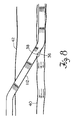
- Figure 8 illustrates the operation of the cannula of the invention after the dilator assembly has been withdrawn and a blood pump attached.
- Figure 9 illustrates the distal flow output of a conventional unidirectional cannula.
- Figure 10 illustrates the distal flow of the bidirectional cannula of the invention.
- Figure 11 illustrates the distal pressure output of a conventional unidirectional cannula.
- Figure 12 illustrates the distal pressure output of a bidirectional cannula of the cannula.
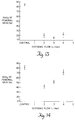
- Figure 13 illustrates the mixed venous oxygen saturation (SVO2) of a conventional unidirectional cannula.
- Figure 14 illustrates the mixed venous oxygen saturation (SVO2) of the bidirectional cannula of the invention.
- the cannula of the invention supplies blood to both the body as well as in the opposite direction to the leg.
- Figure 1 illustrates the simple construction of the bidirectional femoral arterial cannula.
- the cannula is comprised of a radiopaque polyurethane thin wall tube 112, with an outer diameter of 6 mm, which includes a tapered tip 110 with an opening for supplying blood to the main body of the patient.
- Tip 110 has an inner diameter of 4 mm and an outer diameter of 5 mm.
- Tube 112 can be typically 17 French or 14 French in width or other desired sizes as well.
- Figures 5, 6, and 7 illustrate the diverting side hole 38 for supplying blood to the lower extremity of the patient, and barb 36 for positioning the cannula diverting side hole within the blood vessel without blood vessel wall occlusion.
- barb 36 comprises a distal facing portion 39 with a shallow slope and a proximal facing portion 41 with a steep slope.
- the shallow slope of barb portion 39 facilitates insertion of the cannula into the artery.
- the steep slope of barb portion 41 abuts the inner wall of the blood vessel and properly positions the diverting side hole 38.
- Barb 36 is 1 cm in length and 1 mm in height.
- Figure 5 illustrates the symmetrical placement of barbs 36, 5 mm apart, on either side of diverting side hole 38, which is located in a depression diverter 43 on the exterior of the wall of cannula 112 and is 2 mm in diameter.
- diverting side hole 38 is slanted with respect to the wall of cannula 112 and is less likely to be occluded in that position.
- Figure 8 illustrates the placement of the cannula of the invention in a blood vessel for long term cardio-pulmonary patient support.
- the proximal end 111 of cannula 112 is attached to a polyvinylchloride hub assembly 115.
- Hub assembly 115 includes a transparent flexible hub in segments 114, 116, and 22. As shown in Figure 1, barb 36 is located 9 cm from tip 110 and 8.5 cm from hub 115.
- a short hub segment 114 is 1.5 cm in length.
- Hub segment 116 has a clamp area which is 3.5 cm in length extends from flange 118 to hub segment 114.
- the transparent hub provides a visual indication of the entry of the diverting side hole into the blood vessel.
- the hub is connected to a rigid barbed connector 24 which can be coupled to standard 3/8" tubing.
- the hub also includes an air bleed inlet 21 with a screwable cap 20 which permits adjustment of the opening.
- Flanges 118 allow the hub assembly to be sewn or clamped onto the patient's skin and prevent unwanted movement of the cannula. Flanges 118 are shown in more detail in the top view of Figure 2.
- Dilator assembly 30 of Figure 3 serves as an obturator or stiffener and is inserted into the interior of the cannula 112 and its associated hub assembly 115.
- the dilator assembly includes a second polyurethane tube 31 with a distal end 28, 9 cm in length, with a first diameter of 4 mm which occludes the first tube distal tip opening.
- the thickened portion of distal end 28 is 7.5 cm in length.
- Tapered tip 26 on second tube 31 facilitates insertion of the dilator assembly into the first tube of the cannula and dilates the guide wire hole in the vessel for cannula introduction.
- Portion 47 of second tube 31 is 20.5 cm in length and has a second diameter of 3 mm which is less than the first diameter.
- a hollow flash chamber is formed between the first and second tubes which allows blood entering the diverting side hole to flow into the hub assembly region. This provides the physician with a visual indication that the diverting side hole has entered the blood vessel. Only blood from the diverting side hole 38 can enter the flash chamber because the distal end 28 of second tube 31 occludes the distal end 110 of cannula 112.
- a guide wire 35 can also be introduced inside of the second tube 31 to guide the insertion of the cannula into the blood vessel.
- FIG 4(a) The assembled cannula is shown in Figure 4(a).
- Figure 4(b) illustrates the operation of the visual indicator during the insertion of the cannula into the blood vessel.
- the diverting side hole 38 is shown resting on the wall of the blood vessel 40. Diverting side hole 38 is 1.5 cm from the thickened portion of distal end 28 of second tube 31. In this position, blood will fill the hollow chamber 37 between first tube 112 and second tube 31. The blood will flow into the transparent hub region and provide the physician with a visual indication of proper placement.
- the second tube 31 of dilator assembly 30 can also be of radiopaque plastic.
- Figure 4(b) also illustrates the placement of the cannula of the invention using barb 36 and diverting side hole 38.
- Skin 42 in the groin region is pierced using a conventional Seldinger needle.
- Tapered tip 26 on second tube 31 facilitates the dilation of the blood vessel.
- Cannula wall 112 is threaded into blood vessel 40 until the diverting side hole 38 enters the blood vessel.
- blood enters diverting side hole 38 and provides a visual indication in the area of the transparent hub as blood flows into hollow chamber 37.
- the dilator assembly also serves as an obturator or stiffener to assist in the introduction of the cannula. With air bleed hole 21 open, blood can easily flow into the flash chamber 37.
- the dilator assembly is then removed and rigid barb connector 24 is hooked up to standard 3/8" tubing connected to a blood pump circuit.
- the hub segment 116 is clamped after the dilatory assembly is removed. Once connector is attached to the blood pump tubing, the clamp can be removed from hub segment 116.
- the bidirectional cannula of the invention provides adequate distal perfusion of the cannulated lower extremity.
- extended cardiopulmonary assistance can be provided with a greatly reduced risk of ischemia to the lower limb.
- the cannula of the invention can be used with any assist circuit.
- the device could be attached to a percutaneous transseptal left atrial cannulation system. It can also be used for extracorporeal membrane oxygenation where heart function is adequate, but the lungs are failing.
- Any type of blood pump can be used with the cannula of the invention to provide a closed vascular circuit.
- Figures 9-14 show the experimental data which illustrates the ability of the cannula of the invention to maximize pressure, flow, and oxygenation in the cannulated lower extremity.
- Experiments were performed on 90,7 kg (200 pound) pigs in which a conventional unidirectional cannula was inserted in one femoral artery and the bidirectional cannula of the invention was inserted in the other femoral artery.
- Flow probes and pressure catheters were positioned distal to the respective cannulae and measurements were taken over a spectrum of pump flows. Control values are with the pump turned off and before the cannulae are inserted into the femoral artery.
- Figure 9 illustrates the distal flow in an extremity in which a conventional unidirectional cannula has been placed. As can be seen from Figure 9, distal flow is non-existent in the lower extremity at all levels of perfusion. However, as shown in Figure 10, when the bidirectional cannula of the invention is used, distal blood flow exceeds control values at full pump flow.
- Figure 11 illustrates the distal pressure associated the conventional unidirectional cannulation. Blood pressure is minimal even at high flows in the lower extremity. However, when a bidirectional cannula of the invention is used, blood pressure approaches the control value at full flow.
- SVO2 mixed venous oxygen saturation
- the bidirectional femoral arterial cannula of the invention provides adequate flow to the limb in cardiopulmonary assistance circuits used for long term applications.
- the barbed diverting side hole and blood flash chamber are simple to construct and easy to insert into the patient.
- a safe long term method for femoral artery cannulation is provided with minimal risk to the patient.
- Positioning can be accomplished percutaneously without resort to direct surgical exposure or fluoroscopic techniques because of the visual and tactile indications provided to the surgeon by the device.
Abstract
Description
- The invention relates to a bi-directional cannula according to the preamble of
Claim 1. Such a cannula is known from US-A-4 114 618. - In patients experiencing cardiopulmonary failure, a need exists to perfuse blood systemically. A femoral arterial cannula is typically used to infuse oxygenated blood into the body at the groin. To supply an adequate amount of oxygenated blood, the outer diameter of the cannula often occludes the inner diameter of the blood vessel as oxygenated blood is delivered through the lumen within the cannula. Blood exits the cannula from an opening at the distal end which typically directs blood toward the heart of the patient. For patients undergoing long-term cardiopulmonary assistance, the problem of ischemia in the lower extremity arises since the cannula blocks blood flow to the lower leg. A need exists to supply adequate blood flow to the lower leg tissues.
- Prior attempts to obviate ischemia caused by arterial cannula occlusion have been awkward and inadequate. For example, the insertion of an arterial cannula in the aorta to avoid blockage has been suggested. Admittedly, the large diameter of the aorta permits the insertion of a large cannula without resulting in distal occlusion. However, such abdominal or thoracic surgery is invasive and more dangerous than the insertion of a cannula in a femoral artery. These dangers limit invasive techniques to only the most critically ill patients.
- A second cannula can also be used to deliver blood to the lower leg when the femoral artery has been occluded by the systemic cannula. For example, a Y connector and tube could be inserted proximal to the occluding cannula and the distal end of the tube fitted with a catheter which is inserted into the femoral artery distal to the cannula. This also requires extra hardware and another cannulation.
- A longstanding need exists for a bidirectional femoral arterial cannula which will deliver blood in both directions to maintain an adequate flow to the heart as well as in the direction of the lower extremity. The femoral arterial cannula of the invention achieves this bidirectional flow by means of a small diverting hole in the side of the cannula. The bi-directional cannula of the invention comprises a first tube including a proximal end, a distal tip with an opening, a side hole in the tube, at least one barb on the tube exterior for positioning the side hole away from the wall of the blood vessel, the bi-directional cannula being characterized by a diverter in the inside of the tube adjacent to the side hole, said side hole being, thus, a diverting side hole for diverting fluid flow such that fluid flowing in the first tube exits the distal tip opening in a first direction and exits the diverting side hole in a second direction opposite of the first direction. For example, blood is infused in the direction of the lower extremity through the diverting side hole and in the direction of the heart and body through the distal tip opening. The tube can be radiopaque to assist in positioning. However, the cannula can be properly positioned without resorting to fluoroscopic techniques. A cannula wall barb is positioned adjacent the diverting side hole. The barb permits the diverting side hole to be properly positioned in the blood vessel so as not to be occluded by the blood vessel wall. The proximal face of the barb has a steep slope which abuts the inner wall of the blood vessel and prevents the diverting side hole from occluding. The distal facing portion of the barb has a shallow slope which facilitates insertion of the barb into the blood vessel percutaneously over a guide wire.
- The cannula further comprises a hub assembly connected to the proximal end of the first tube. The hub assembly includes a transparent flexible hub such that when the diverting side hole enters the blood vessel, blood flows into the hub region and provides a visual indication of the entry of the diverting side hole into the blood vessel. The cannula invention also includes a dilator assembly which is positioned inside the first tube. The dilator assembly is comprised of a distal end with a diameter which occludes the distal opening of the first tube. The proximal end of the dilator has a smaller diameter and serves as an obturator which stiffens the dilator assembly. The dilator assembly also includes a dilator hub which inserts into the hub assembly of the first tube such that a hollow passage is formed between the first and second tubes which allows blood from the diverting side hole to flow into the transparent hub assembly region. The dilator assembly further includes a guide wire channel within the second tube which allows for percutaneous insertion of the bidirectional cannula. As noted previously, the hollow passage serves as a flash chamber which provides a visual indication of when the diverting side hole enters the blood vessel. The hub assembly also includes a flange which can be used to fasten the entire cannula assembly to the patient's skin.
- The addition of a diverting side hole, barb, and a hollow flash chamber for a visual indication of the entrance of the diverting side hole affords easy percutaneous insertion and proper placement of the bidirectional cannula in a femoral artery. The cannula is inserted into the femoral artery until the diverting side hole is inside of the blood vessel. At this point, blood flows into the transparent passage and flash chamber between the first and second tubes. This provides a positive visual indication to the physician that the diverting side hole is adequately within the blood vessel. The dilator assembly is then withdrawn and the proximal end of the cannula attached to a pump circuit. Thus, the distal end opening of the cannula provides systemic blood flow to the body while the diverting side hole provides blood flow to the leg. Ischemia and possible necrosis are thus avoided in patients undergoing extended cardiopulmonary assistance.
- The above and other features of the invention including various novel details of construction and combinations of parts will now be more particularly described with reference to the accompanying drawings and pointed out in the claims. It will be understood that the particular device embodying the invention is shown by way of illustration only and not as a limitation of the invention. The principles and features of this invention as specified in the claims may be employed in varied and numerous embodiments without departing from the scope of the invention.
- Figure 1 shows a side view of the cannula of the invention.
- Figure 2 shows a top view of the cannula of the invention.
- Figure 3 illustrates the dilator assembly of the cannula of the invention.
- Figure 4(a) shows the combined cannula and dilator assembly of the invention.
- Figure 4(b) illustrates the initial placement of the cannula of the invention in a femoral artery and the operation of the visual indicators of the cannula.
- Figure 5 shows a cross-sectional view of the cannula of Figure 1.
- Figure 6 illustrates a longitudinal cross-sectional view of the cannula which encompasses the diverting side hole.
- Figure 7 illustrates a longitudinal cross-sectional view of the cannula which encompasses the protuberances.
- Figure 8 illustrates the operation of the cannula of the invention after the dilator assembly has been withdrawn and a blood pump attached.
- Figure 9 illustrates the distal flow output of a conventional unidirectional cannula.
- Figure 10 illustrates the distal flow of the bidirectional cannula of the invention.
- Figure 11 illustrates the distal pressure output of a conventional unidirectional cannula.
- Figure 12 illustrates the distal pressure output of a bidirectional cannula of the cannula.
- Figure 13 illustrates the mixed venous oxygen saturation (SVO₂) of a conventional unidirectional cannula.
- Figure 14 illustrates the mixed venous oxygen saturation (SVO₂) of the bidirectional cannula of the invention.
- To prevent lower extremity ischemia and resulting tissue necrosis, the cannula of the invention supplies blood to both the body as well as in the opposite direction to the leg. Figure 1 illustrates the simple construction of the bidirectional femoral arterial cannula. The cannula is comprised of a radiopaque polyurethane
thin wall tube 112, with an outer diameter of 6 mm, which includes a taperedtip 110 with an opening for supplying blood to the main body of the patient.Tip 110 has an inner diameter of 4 mm and an outer diameter of 5 mm.Tube 112 can be typically 17 French or 14 French in width or other desired sizes as well. Figures 5, 6, and 7 illustrate the divertingside hole 38 for supplying blood to the lower extremity of the patient, andbarb 36 for positioning the cannula diverting side hole within the blood vessel without blood vessel wall occlusion. - As shown in Figure 7,
barb 36 comprises a distal facingportion 39 with a shallow slope and a proximal facingportion 41 with a steep slope. The shallow slope ofbarb portion 39 facilitates insertion of the cannula into the artery. The steep slope ofbarb portion 41 abuts the inner wall of the blood vessel and properly positions the divertingside hole 38.Barb 36 is 1 cm in length and 1 mm in height. Figure 5 illustrates the symmetrical placement ofbarbs side hole 38, which is located in adepression diverter 43 on the exterior of the wall ofcannula 112 and is 2 mm in diameter. As shown in Figure 6, divertingside hole 38 is slanted with respect to the wall ofcannula 112 and is less likely to be occluded in that position. Figure 8 illustrates the placement of the cannula of the invention in a blood vessel for long term cardio-pulmonary patient support. - The proximal end 111 of
cannula 112 is attached to apolyvinylchloride hub assembly 115.Hub assembly 115 includes a transparent flexible hub insegments barb 36 is located 9 cm fromtip 110 and 8.5 cm fromhub 115. Ashort hub segment 114 is 1.5 cm in length.Hub segment 116 has a clamp area which is 3.5 cm in length extends fromflange 118 tohub segment 114. As will be shown below, the transparent hub provides a visual indication of the entry of the diverting side hole into the blood vessel. The hub is connected to a rigidbarbed connector 24 which can be coupled to standard 3/8" tubing. The hub also includes anair bleed inlet 21 with ascrewable cap 20 which permits adjustment of the opening.Flanges 118 allow the hub assembly to be sewn or clamped onto the patient's skin and prevent unwanted movement of the cannula.Flanges 118 are shown in more detail in the top view of Figure 2. -
Dilator assembly 30 of Figure 3 serves as an obturator or stiffener and is inserted into the interior of thecannula 112 and its associatedhub assembly 115. The dilator assembly includes asecond polyurethane tube 31 with adistal end 28, 9 cm in length, with a first diameter of 4 mm which occludes the first tube distal tip opening. The thickened portion ofdistal end 28 is 7.5 cm in length.Tapered tip 26 onsecond tube 31 facilitates insertion of the dilator assembly into the first tube of the cannula and dilates the guide wire hole in the vessel for cannula introduction. A polypropylene dilator hub with a taperedportion 32 seals inside of the rigidbarbed connector 24 ofhub assembly 115 andouter hub 34 is a handle for manipulation of the dilator.Portion 47 ofsecond tube 31 is 20.5 cm in length and has a second diameter of 3 mm which is less than the first diameter. Thus, a hollow flash chamber is formed between the first and second tubes which allows blood entering the diverting side hole to flow into the hub assembly region. This provides the physician with a visual indication that the diverting side hole has entered the blood vessel. Only blood from the divertingside hole 38 can enter the flash chamber because thedistal end 28 ofsecond tube 31 occludes thedistal end 110 ofcannula 112. Aguide wire 35 can also be introduced inside of thesecond tube 31 to guide the insertion of the cannula into the blood vessel. - The assembled cannula is shown in Figure 4(a). Figure 4(b) illustrates the operation of the visual indicator during the insertion of the cannula into the blood vessel. The diverting
side hole 38 is shown resting on the wall of theblood vessel 40. Divertingside hole 38 is 1.5 cm from the thickened portion ofdistal end 28 ofsecond tube 31. In this position, blood will fill thehollow chamber 37 betweenfirst tube 112 andsecond tube 31. The blood will flow into the transparent hub region and provide the physician with a visual indication of proper placement. Thesecond tube 31 ofdilator assembly 30 can also be of radiopaque plastic. - Figure 4(b) also illustrates the placement of the cannula of the
invention using barb 36 and divertingside hole 38.Skin 42 in the groin region is pierced using a conventional Seldinger needle.Tapered tip 26 onsecond tube 31 facilitates the dilation of the blood vessel.Cannula wall 112 is threaded intoblood vessel 40 until the divertingside hole 38 enters the blood vessel. As noted previously, blood enters divertingside hole 38 and provides a visual indication in the area of the transparent hub as blood flows intohollow chamber 37. The dilator assembly also serves as an obturator or stiffener to assist in the introduction of the cannula. Withair bleed hole 21 open, blood can easily flow into theflash chamber 37. The dilator assembly is then removed andrigid barb connector 24 is hooked up to standard 3/8" tubing connected to a blood pump circuit. Thehub segment 116 is clamped after the dilatory assembly is removed. Once connector is attached to the blood pump tubing, the clamp can be removed fromhub segment 116. - The bidirectional cannula of the invention provides adequate distal perfusion of the cannulated lower extremity. Thus, extended cardiopulmonary assistance can be provided with a greatly reduced risk of ischemia to the lower limb. The cannula of the invention can be used with any assist circuit. For example, the device could be attached to a percutaneous transseptal left atrial cannulation system. It can also be used for extracorporeal membrane oxygenation where heart function is adequate, but the lungs are failing. Any type of blood pump can be used with the cannula of the invention to provide a closed vascular circuit.
- Figures 9-14 show the experimental data which illustrates the ability of the cannula of the invention to maximize pressure, flow, and oxygenation in the cannulated lower extremity. Experiments were performed on 90,7 kg (200 pound) pigs in which a conventional unidirectional cannula was inserted in one femoral artery and the bidirectional cannula of the invention was inserted in the other femoral artery. Flow probes and pressure catheters were positioned distal to the respective cannulae and measurements were taken over a spectrum of pump flows. Control values are with the pump turned off and before the cannulae are inserted into the femoral artery. Figure 9 illustrates the distal flow in an extremity in which a conventional unidirectional cannula has been placed. As can be seen from Figure 9, distal flow is non-existent in the lower extremity at all levels of perfusion. However, as shown in Figure 10, when the bidirectional cannula of the invention is used, distal blood flow exceeds control values at full pump flow.
- Similar data is produced when distal pressure is measured. For example, Figure 11 illustrates the distal pressure associated the conventional unidirectional cannulation. Blood pressure is minimal even at high flows in the lower extremity. However, when a bidirectional cannula of the invention is used, blood pressure approaches the control value at full flow.
- Finally, the mixed venous oxygen saturation (SVO₂) was measured as an index of total limb perfusion, both directly from the cannula and also from native collateral vessels. Low SVO₂ indicates poor perfusion and with a unidirectional cannula in place it indicates that collateral flow contributes very little to overall limb perfusion. Conversely, high SVO₂ indicates good limb perfusion. The unidirectional cannula in Figure 13 is associated with minimal direct or collateral flow whereas the bidirectional cannula in Figure 14 produces almost a nominal SVO₂ at high flows.
- The bidirectional femoral arterial cannula of the invention provides adequate flow to the limb in cardiopulmonary assistance circuits used for long term applications. The barbed diverting side hole and blood flash chamber are simple to construct and easy to insert into the patient. Thus, a safe long term method for femoral artery cannulation is provided with minimal risk to the patient. Positioning can be accomplished percutaneously without resort to direct surgical exposure or fluoroscopic techniques because of the visual and tactile indications provided to the surgeon by the device.
Claims (7)
- A bi-directional cannula comprising a first tube (112) including:(i) a proximal end (111);(ii) a distal tip (110) with an opening;(iii) a side hole (38) in the tube;(iv) at least one barb (36) on the tube exterior for positioning the side hole (38) away from the wall of the blood vessel;
characterized by:
a diverter (43) in the inside of the tube adjacent to the side hole (38), said side hole being, thus, a diverting side hole (38) for diverting fluid flow such that fluid flowing in the first tube (112) exits the distal tip opening (110) in a first direction and exits the diverting side hole (38) in a second direction opposite of the first direction. - A cannula according to Claim 1, wherein the first tube (112) is radiopaque.
- A cannula according to Claim 1 or Claim 2, wherein the first tube (112) further comprises a first barb (36) and a second barb (36) which are positioned adjacent the diverting side hole (38).
- A cannula according to Claim 3, wherein the diverting side hole (38) is positioned in the depression (43) in the first tube (112) exterior between the first and second barbs (36).
- A cannula according to any one of the preceding claims, further comprising a hub assembly (115) connected to the proximal end (111) of the first tube (112), said hub assembly (115) including a transparent flexible hub region (114, 116 and 22) such that when the diverting side hole (38) enters the blood vessel, blood flows into the hub region (114, 116, 22) and provides a visual indication of the proper placement of the diverting side hole (38).
- A cannula according to Claim 5, further comprising a dilator assembly (30) which is positioned inside of the first tube (112), including:(i) a second tube (31) having a distal end (28) with a first diameter which occludes the first tube distal tip opening (110) and a proximal end (47) with a second diameter which is less than the first diameter, and(ii) a dilator hub (32 and 34) which is connected to the hub assembly (115) and the proximal end of the second tube (31) such that a hollow passage is formed between the first tube (112) and second tube (31) which allows blood entering the diverting side hole (38) to flow into the hub assembly (115).
- A cannula according to any one of the preceding claims, wherein the barb (36) further comprises:a) a distal facing portion (39) with a shallow slope which facilitates insertion of the cannula into a blood vessel; andb) a proximal facing portion (41) with a steep slope which may abut the inner wall of the blood vessel and prevent inadvertent extraction of the diverting side hole (38) outside of the vessel.
Applications Claiming Priority (3)
| Application Number | Priority Date | Filing Date | Title |
|---|---|---|---|
| US816874 | 1992-01-02 | ||
| US07/816,874 US5171218A (en) | 1992-01-02 | 1992-01-02 | Bidirectional femoral arterial cannula |
| PCT/US1992/011141 WO1993012826A1 (en) | 1992-01-02 | 1992-12-21 | A bidirectional femoral arterial cannula |
Publications (2)
| Publication Number | Publication Date |
|---|---|
| EP0619745A1 EP0619745A1 (en) | 1994-10-19 |
| EP0619745B1 true EP0619745B1 (en) | 1995-10-11 |
Family
ID=25221828
Family Applications (1)
| Application Number | Title | Priority Date | Filing Date |
|---|---|---|---|
| EP93902702A Expired - Lifetime EP0619745B1 (en) | 1992-01-02 | 1992-12-21 | A bidirectional femoral arterial cannula |
Country Status (7)
| Country | Link |
|---|---|
| US (2) | US5171218A (en) |
| EP (1) | EP0619745B1 (en) |
| JP (1) | JP3325269B2 (en) |
| AT (1) | ATE128876T1 (en) |
| DE (1) | DE69205441T2 (en) |
| ES (1) | ES2081208T3 (en) |
| WO (1) | WO1993012826A1 (en) |
Cited By (2)
| Publication number | Priority date | Publication date | Assignee | Title |
|---|---|---|---|---|
| US10226595B2 (en) | 2014-06-16 | 2019-03-12 | Edwards Lifesciences Corporation | Spring cannulae |
| USD975844S1 (en) | 2019-11-06 | 2023-01-17 | Free Life Medical Gmbh | Cannula |
Families Citing this family (105)
| Publication number | Priority date | Publication date | Assignee | Title |
|---|---|---|---|---|
| US6770074B2 (en) * | 1988-06-13 | 2004-08-03 | Gary Karlin Michelson | Apparatus for use in inserting spinal implants |
| CN1128944A (en) | 1988-06-13 | 1996-08-14 | 卡林技术公司 | Apparatus and method of inserting spinal implants |
| US5766151A (en) * | 1991-07-16 | 1998-06-16 | Heartport, Inc. | Endovascular system for arresting the heart |
| US5795325A (en) | 1991-07-16 | 1998-08-18 | Heartport, Inc. | Methods and apparatus for anchoring an occluding member |
| US6482171B1 (en) | 1991-07-16 | 2002-11-19 | Heartport, Inc. | Multi-lumen catheter |
| US5879499A (en) * | 1996-06-17 | 1999-03-09 | Heartport, Inc. | Method of manufacture of a multi-lumen catheter |
| US5171218A (en) * | 1992-01-02 | 1992-12-15 | Trustees Of Boston University | Bidirectional femoral arterial cannula |
| US5431639A (en) * | 1993-08-12 | 1995-07-11 | Boston Scientific Corporation | Treating wounds caused by medical procedures |
| US5863366A (en) * | 1995-06-07 | 1999-01-26 | Heartport, Inc. | Method of manufacture of a cannula for a medical device |
| US5662619A (en) * | 1995-11-27 | 1997-09-02 | Zarate; Alfredo R. | Venous dialysis needle |
| US5792044A (en) * | 1996-03-22 | 1998-08-11 | Danek Medical, Inc. | Devices and methods for percutaneous surgery |
| US6110145A (en) * | 1996-04-16 | 2000-08-29 | Cardeon Corporation | Catheter system for surgical access and circulatory support of the heart |
| US5810780A (en) * | 1996-05-10 | 1998-09-22 | Becton Dickinson And Company | Multiple cross section needle and elastic plug assembly for a medical device |
| US5830190A (en) * | 1996-06-11 | 1998-11-03 | Becton Dickinson And Company | Protected needle catheter placement device having needle placement visualization features and method for its use |
| US6050924A (en) * | 1997-04-28 | 2000-04-18 | Shea; Michael J. | Exercise system |
| US6068608A (en) * | 1997-05-01 | 2000-05-30 | Chase Medical, Inc. | Method of using integral aortic arch infusion clamp |
| US6132397A (en) * | 1997-05-01 | 2000-10-17 | Chase Medical Inc. | Integral aortic arch infusion clamp catheter |
| US6217546B1 (en) | 1997-05-19 | 2001-04-17 | United States Surgical Corporation | Catheter system |
| WO1999004845A2 (en) * | 1997-07-22 | 1999-02-04 | Chase Medical Inc. | Catheter having a lumen occluding balloon and method of use thereof |
| US6241699B1 (en) | 1998-07-22 | 2001-06-05 | Chase Medical, Inc. | Catheter system and method for posterior epicardial revascularization and intracardiac surgery on a beating heart |
| US6099506A (en) | 1997-09-26 | 2000-08-08 | Macoviak; John A. | Introducer and perfusion cannula |
| US6889082B2 (en) | 1997-10-09 | 2005-05-03 | Orqis Medical Corporation | Implantable heart assist system and method of applying same |
| US5976114A (en) | 1998-04-30 | 1999-11-02 | Medtronic, Inc. | Aortic cannula with reduced velocity flow-through tip |
| US6508777B1 (en) | 1998-05-08 | 2003-01-21 | Cardeon Corporation | Circulatory support system and method of use for isolated segmental perfusion |
| US6726651B1 (en) | 1999-08-04 | 2004-04-27 | Cardeon Corporation | Method and apparatus for differentially perfusing a patient during cardiopulmonary bypass |
| US6210363B1 (en) | 1999-02-23 | 2001-04-03 | Cardeon Corporation | Methods and devices for occluding a vessel and performing differential perfusion |
| US6186981B1 (en) | 1999-03-23 | 2001-02-13 | Peter Cho | Cavo-atrial cannula |
| US6676650B1 (en) * | 1999-09-22 | 2004-01-13 | Cardiacassist, Inc. | Perfusion cannula, method and system |
| US6530876B1 (en) | 2000-04-25 | 2003-03-11 | Paul A. Spence | Supplemental heart pump methods and systems for supplementing blood through the heart |
| US6808508B1 (en) * | 2000-09-13 | 2004-10-26 | Cardiacassist, Inc. | Method and system for closed chest blood flow support |
| US6702835B2 (en) | 2001-09-07 | 2004-03-09 | Core Medical, Inc. | Needle apparatus for closing septal defects and methods for using such apparatus |
| US6776784B2 (en) | 2001-09-06 | 2004-08-17 | Core Medical, Inc. | Clip apparatus for closing septal defects and methods of use |
| US20060052821A1 (en) | 2001-09-06 | 2006-03-09 | Ovalis, Inc. | Systems and methods for treating septal defects |
| WO2003057272A2 (en) * | 2001-12-26 | 2003-07-17 | Yale University | Vascular access device |
| US20050267401A1 (en) * | 2004-05-25 | 2005-12-01 | Sherwood Services, Ag. | Safety interlock system for an enteral feeding pump |
| US7273446B2 (en) | 2003-10-31 | 2007-09-25 | Spence Paul A | Methods, devices and systems for counterpulsation of blood flow to and from the circulatory system |
| WO2005049110A2 (en) * | 2003-11-15 | 2005-06-02 | Medrad, Inc. | Catheter for diagnostic imaging and therapeutic procedures |
| WO2005112796A2 (en) * | 2004-05-12 | 2005-12-01 | Nellcor Puritan Bennett Incorporated | Endotracheal tube having improved suction lumen |
| US8721592B2 (en) * | 2006-01-25 | 2014-05-13 | Thermopeutix, Inc. | Variable length catheter for drug delivery |
| KR20080011179A (en) * | 2005-03-30 | 2008-01-31 | 엑세스 싸이언티픽, 인크. | Vascular access |
| US8579936B2 (en) | 2005-07-05 | 2013-11-12 | ProMed, Inc. | Centering of delivery devices with respect to a septal defect |
| US8257323B2 (en) * | 2005-08-03 | 2012-09-04 | Medtronic, Inc. | Cannula system and method |
| US7846179B2 (en) | 2005-09-01 | 2010-12-07 | Ovalis, Inc. | Suture-based systems and methods for treating septal defects |
| US8550973B2 (en) * | 2006-01-09 | 2013-10-08 | Cardiacassist, Inc. | Percutaneous right ventricular assist apparatus and method |
| WO2007090050A2 (en) * | 2006-01-27 | 2007-08-09 | Circulite, Inc. | Heart assist system |
| JP4504941B2 (en) * | 2006-04-25 | 2010-07-14 | テルモ株式会社 | Thrombus aspiration catheter |
| US7905823B2 (en) * | 2006-08-30 | 2011-03-15 | Circulite, Inc. | Devices, methods and systems for establishing supplemental blood flow in the circulatory system |
| WO2008027869A2 (en) | 2006-08-30 | 2008-03-06 | Circulite, Inc. | Devices, methods and systems for establishing supplemental blood flow in the circulatory system |
| US8333686B2 (en) * | 2006-08-30 | 2012-12-18 | Circulite, Inc. | Cannula insertion devices, systems, and methods including a compressible member |
| US8876754B2 (en) * | 2006-08-31 | 2014-11-04 | Bayer Medical Care Inc. | Catheter with filtering and sensing elements |
| EP2061531B1 (en) * | 2006-09-14 | 2016-04-13 | CircuLite, Inc. | Intravascular blood pump and catheter |
| US7922696B2 (en) | 2007-01-24 | 2011-04-12 | Access Scientific, Inc. | Access device |
| US8192402B2 (en) | 2007-04-18 | 2012-06-05 | Access Scientific, Inc. | Access device |
| WO2008131300A2 (en) | 2007-04-18 | 2008-10-30 | Access Scientific, Inc. | Access device |
| CA2693223C (en) * | 2007-07-19 | 2015-05-19 | Circulite, Inc. | Cannula for heart chamber implantation and related systems |
| US8343029B2 (en) * | 2007-10-24 | 2013-01-01 | Circulite, Inc. | Transseptal cannula, tip, delivery system, and method |
| US8202251B2 (en) | 2008-03-14 | 2012-06-19 | Access Scientific, Inc. | Access device |
| USD601242S1 (en) | 2008-03-14 | 2009-09-29 | Access Scientific, Inc. | Access device |
| JP2011515127A (en) * | 2008-03-14 | 2011-05-19 | アクセス サイエンティフィック、インク. | Access device |
| JP2009273609A (en) | 2008-05-14 | 2009-11-26 | Nippon Sherwood Medical Industries Ltd | Catheter with valve |
| USD600793S1 (en) | 2008-09-10 | 2009-09-22 | Access Scientific, Inc. | Access device |
| US9005154B2 (en) | 2008-09-26 | 2015-04-14 | Covidien Lp | Valved hemodialysis catheter |
| WO2010056906A2 (en) * | 2008-11-12 | 2010-05-20 | Access Scientific, Inc. | Access device |
| US8460168B2 (en) * | 2009-03-27 | 2013-06-11 | Circulite, Inc. | Transseptal cannula device, coaxial balloon delivery device, and methods of using the same |
| US20100249491A1 (en) * | 2009-03-27 | 2010-09-30 | Circulite, Inc. | Two-piece transseptal cannula, delivery system, and method of delivery |
| US20120078095A1 (en) * | 2009-05-05 | 2012-03-29 | Heck Robert W | High-flow tapered peripheral iv catheter with side outlets |
| US9393382B2 (en) * | 2009-05-05 | 2016-07-19 | Robert W. Heck | High-flow tapered peripheral IV catheter with side outlets |
| US8827958B2 (en) | 2009-05-12 | 2014-09-09 | Access Scientific, Llc | Access device with valve |
| JP2011050420A (en) | 2009-08-31 | 2011-03-17 | Nippon Sherwood Medical Industries Ltd | Valved catheter |
| US20110112353A1 (en) * | 2009-11-09 | 2011-05-12 | Circulite, Inc. | Bifurcated outflow cannulae |
| US20110152915A1 (en) * | 2009-12-21 | 2011-06-23 | Tamer Ibrahim | Hemostatic stabilization system |
| US9339599B2 (en) * | 2009-12-21 | 2016-05-17 | Sorin Group Usa, Inc. | Self-dilating cannula |
| US8562519B2 (en) | 2009-12-31 | 2013-10-22 | Cardiacassist, Inc. | Pumping system and method for assisting a patient's heart |
| WO2011097639A2 (en) | 2010-02-08 | 2011-08-11 | Access Scientific, Inc. | Access device |
| CN103228300A (en) | 2010-09-07 | 2013-07-31 | 保罗·A·斯彭斯 | Cannula systems and methods |
| US8795253B2 (en) | 2011-04-05 | 2014-08-05 | Sorin Group Italia S.R.L. | Bi-directional perfusion cannula |
| US9884169B2 (en) | 2011-08-17 | 2018-02-06 | Access Scientific, Llc | Access device with valve |
| US8747343B2 (en) | 2011-09-30 | 2014-06-10 | Covidien Lp | Hemodialysis catheter with improved side opening design |
| US9072867B2 (en) | 2011-09-30 | 2015-07-07 | Covidien Lp | Catheter with external flow channel |
| US10143822B2 (en) | 2012-07-05 | 2018-12-04 | Covidien Lp | Valved tip catheters |
| WO2014062827A1 (en) | 2012-10-16 | 2014-04-24 | Spence Paul A | Devices, systems, and methods for facilitating flow from the heart to a blood pump |
| US9566087B2 (en) | 2013-03-15 | 2017-02-14 | Access Scientific, Llc | Vascular access device |
| EP2829226B1 (en) * | 2013-07-24 | 2021-03-24 | novalung GmbH | Perfusion cannula with integrated sensors |
| WO2015085094A1 (en) | 2013-12-04 | 2015-06-11 | Heartware, Inc. | Apparatus and methods for cutting an atrial wall |
| SG11201606240UA (en) * | 2014-01-30 | 2016-08-30 | Singapore Health Serv Pte Ltd | Arterial sheath which allows distal perfusion within a cannulated vessel |
| US20170232238A1 (en) | 2014-08-06 | 2017-08-17 | Edwars Litesciences Corporation | Multi-lumen cannulae |
| US9981119B2 (en) * | 2014-10-29 | 2018-05-29 | Edwards Lifesciences Corporation | Bi-directional cannula |
| KR20160103474A (en) * | 2015-02-24 | 2016-09-01 | 사회복지법인 삼성생명공익재단 | Femoral arterial Cannula capable of guidance of bidirectional flow |
| DE102015005002A1 (en) | 2015-04-21 | 2016-10-27 | Xenios Ag | cannula |
| US11027099B2 (en) | 2015-04-30 | 2021-06-08 | Smiths Medical Asd, Inc. | Vascular access device |
| WO2017075528A1 (en) | 2015-10-30 | 2017-05-04 | ECMOtek, LLC | Devices for endovascular access through extracorporeal life support circuits |
| JP7032809B2 (en) * | 2016-10-06 | 2022-03-09 | 株式会社北里コーポレーション | Living cell transplant tool |
| FR3058642B1 (en) | 2016-11-15 | 2023-03-10 | Hopitaux Paris Assist Publique | CANNULA AND OXYGENATION SYSTEM BY EXTRACORPORAL MEMBRANE COMPRISING SUCH CANNULA |
| TR201704099A2 (en) | 2017-03-17 | 2018-09-21 | T C Istanbul Medipol Ueniversitesi | A FEMORAL ARTERIAL ECMO (EXTRACORPOREAL MEMBRANE OXYGENATION EXTRACORPOREAL MEMBRANE OXYGENATION) CANNULA |
| JP7071398B2 (en) | 2017-04-14 | 2022-05-18 | スミスズ メディカル エーエスディー,インコーポレイティド | Vascular access device |
| IT201700110730A1 (en) | 2017-10-03 | 2019-04-03 | Paolo Peruzzo | CANNULA FOR THE PERFUSION OF A FLUID |
| EP3694577A4 (en) | 2017-10-10 | 2021-07-07 | University of Maryland, Baltimore | Bidirectional flow catheter |
| US10569059B2 (en) | 2018-03-01 | 2020-02-25 | Asspv, Llc | Guidewire retention device |
| WO2020161586A1 (en) | 2019-02-04 | 2020-08-13 | Contract Medical International Gmbh | Systems and methods for diverting blood flow in blood vessels |
| EP3735996B1 (en) | 2019-05-07 | 2023-09-27 | Free Life Medical GmbH | Bi-directional perfusion cannula |
| KR102032447B1 (en) * | 2019-07-26 | 2019-10-15 | 사회복지법인 삼성생명공익재단 | Femoral arterial Cannula capable of guidance of bidirectional flow |
| TWI724682B (en) | 2019-12-11 | 2021-04-11 | 林伯彥 | Bidirectional vascular tube device |
| CN113082452B (en) * | 2020-01-08 | 2023-02-17 | 西安西京医疗用品有限公司 | Femoral artery cannula |
| CN112915294A (en) * | 2021-01-25 | 2021-06-08 | 安徽医科大学第一附属医院 | VA-ECMO femoral artery intubation tube for providing lower limb blood perfusion and intubation method |
| EP4108268A1 (en) | 2021-06-22 | 2022-12-28 | Jawad Salman | Bi-directional cannula |
Family Cites Families (23)
| Publication number | Priority date | Publication date | Assignee | Title |
|---|---|---|---|---|
| US1879249A (en) * | 1931-04-07 | 1932-09-27 | Honsaker Charles Coy | Colonic tube |
| US3605750A (en) * | 1969-04-07 | 1971-09-20 | David S Sheridan | X-ray tip catheter |
| US3769980A (en) * | 1971-06-28 | 1973-11-06 | Medical Concepts Inc | Medical instruments |
| US3828767A (en) * | 1973-10-29 | 1974-08-13 | Fenton J | Angiographic and arteriographic catherters |
| US4114618A (en) * | 1976-12-15 | 1978-09-19 | Vargas Jorge J | Catheter assembly |
| US4180068A (en) * | 1978-04-13 | 1979-12-25 | Motion Control, Incorporated | Bi-directional flow catheter with retractable trocar/valve structure |
| WO1982004442A1 (en) * | 1981-06-19 | 1982-12-23 | Stangroom James Edward | Electroviscous fluids |
| JPS58120138A (en) * | 1982-01-12 | 1983-07-16 | Toshiba Corp | Load cell |
| US4531935A (en) * | 1983-01-13 | 1985-07-30 | Med-West, Incorporated | Cardioplegia/air aspiration cannula |
| ES533509A1 (en) * | 1983-07-18 | 1985-09-01 | Abbott Lab | Catheter flashback indicator. |
| US4543087A (en) * | 1983-11-14 | 1985-09-24 | Quinton Instrument Company | Double lumen catheter tip |
| JPS61202597A (en) * | 1985-03-06 | 1986-09-08 | Alps Electric Co Ltd | Remote operating device |
| JPS62185498A (en) * | 1986-02-10 | 1987-08-13 | Victor Co Of Japan Ltd | Remote controller |
| JPS6349888A (en) * | 1986-08-19 | 1988-03-02 | Mitsubishi Electric Corp | Gradation correcting system |
| JPS63244936A (en) * | 1987-03-30 | 1988-10-12 | Matsushita Electric Ind Co Ltd | Receiver |
| JPS63287194A (en) * | 1987-05-20 | 1988-11-24 | Nippon Hoso Kyokai <Nhk> | Signal transmitter for remote control |
| US4863441A (en) * | 1987-07-17 | 1989-09-05 | Minnesota Mining And Manufacturing Company | Venous return catheter |
| JPH07121118B2 (en) * | 1987-12-03 | 1995-12-20 | キヤノン株式会社 | Image information processing device |
| US4895564A (en) * | 1988-06-08 | 1990-01-23 | Farrell Edward M | Percutaneous femoral bypass system |
| US4994027A (en) * | 1988-06-08 | 1991-02-19 | Farrell Edward M | Percutaneous femoral bypass system |
| DE3903119C1 (en) * | 1989-02-02 | 1990-08-09 | Willy Ruesch Ag, 7053 Kernen, De | |
| US5147334A (en) * | 1991-01-02 | 1992-09-15 | Moss James P | Catheter for cholangiography |
| US5171218A (en) * | 1992-01-02 | 1992-12-15 | Trustees Of Boston University | Bidirectional femoral arterial cannula |
-
1992
- 1992-01-02 US US07/816,874 patent/US5171218A/en not_active Expired - Lifetime
- 1992-09-18 US US07/947,306 patent/US5330433A/en not_active Expired - Lifetime
- 1992-12-21 DE DE69205441T patent/DE69205441T2/en not_active Expired - Fee Related
- 1992-12-21 WO PCT/US1992/011141 patent/WO1993012826A1/en active IP Right Grant
- 1992-12-21 AT AT93902702T patent/ATE128876T1/en active
- 1992-12-21 JP JP51185393A patent/JP3325269B2/en not_active Expired - Fee Related
- 1992-12-21 ES ES93902702T patent/ES2081208T3/en not_active Expired - Lifetime
- 1992-12-21 EP EP93902702A patent/EP0619745B1/en not_active Expired - Lifetime
Cited By (2)
| Publication number | Priority date | Publication date | Assignee | Title |
|---|---|---|---|---|
| US10226595B2 (en) | 2014-06-16 | 2019-03-12 | Edwards Lifesciences Corporation | Spring cannulae |
| USD975844S1 (en) | 2019-11-06 | 2023-01-17 | Free Life Medical Gmbh | Cannula |
Also Published As
| Publication number | Publication date |
|---|---|
| US5330433A (en) | 1994-07-19 |
| DE69205441T2 (en) | 1996-05-30 |
| EP0619745A1 (en) | 1994-10-19 |
| WO1993012826A1 (en) | 1993-07-08 |
| US5171218A (en) | 1992-12-15 |
| JP3325269B2 (en) | 2002-09-17 |
| ES2081208T3 (en) | 1996-02-16 |
| ATE128876T1 (en) | 1995-10-15 |
| JPH07502443A (en) | 1995-03-16 |
| DE69205441D1 (en) | 1995-11-16 |
Similar Documents
| Publication | Publication Date | Title |
|---|---|---|
| EP0619745B1 (en) | A bidirectional femoral arterial cannula | |
| US20230001136A1 (en) | Bl-DIRECTIONAL PERFUSION CANNULA | |
| EP1076573B1 (en) | Circulatory support system for isolated segmental perfusion | |
| US7300430B2 (en) | Multi-lumen catheter with attachable hub | |
| AU2002240049B2 (en) | Multi-lumen catheter with attachable hub | |
| CA1336320C (en) | Femoral arterial cannula | |
| CA2288755C (en) | Catheter system | |
| EP0286756A1 (en) | Vascular cannulae for transfemoral cardiopulmonary bypass and method of use | |
| US20090187133A1 (en) | Appliance for cannulation of a blood vessel | |
| US7204831B2 (en) | Guidewire retrieval member for catheter insertion | |
| US8500689B2 (en) | Device for cannulation of a hollow organ | |
| US20220355011A1 (en) | Dual lumen cannula with expandable lumen | |
| EP1374930A1 (en) | Circulatory support system for isolated segmental perfusion | |
| US5221257A (en) | Apparatus and method for femoral venous cannulation | |
| US5735828A (en) | Method and device for catheterization | |
| CN116271298A (en) | Atrial septum puncture double-cavity VA-ECMO cannula | |
| Arab et al. | Variety and Classification of ECMO Systems and Cannulation Strategies |
Legal Events
| Date | Code | Title | Description |
|---|---|---|---|
| PUAI | Public reference made under article 153(3) epc to a published international application that has entered the european phase |
Free format text: ORIGINAL CODE: 0009012 |
|
| 17P | Request for examination filed |
Effective date: 19940630 |
|
| AK | Designated contracting states |
Kind code of ref document: A1 Designated state(s): AT BE CH DE DK ES FR GB GR IE IT LI LU MC NL PT SE |
|
| 17Q | First examination report despatched |
Effective date: 19941206 |
|
| GRAA | (expected) grant |
Free format text: ORIGINAL CODE: 0009210 |
|
| AK | Designated contracting states |
Kind code of ref document: B1 Designated state(s): AT BE CH DE DK ES FR GB GR IE IT LI LU MC NL PT SE |
|
| PG25 | Lapsed in a contracting state [announced via postgrant information from national office to epo] |
Ref country code: MC Free format text: LAPSE BECAUSE OF NON-PAYMENT OF DUE FEES Effective date: 19951011 Ref country code: GR Free format text: LAPSE BECAUSE OF FAILURE TO SUBMIT A TRANSLATION OF THE DESCRIPTION OR TO PAY THE FEE WITHIN THE PRESCRIBED TIME-LIMIT Effective date: 19951011 Ref country code: DK Effective date: 19951011 Ref country code: AT Effective date: 19951011 |
|
| REF | Corresponds to: |
Ref document number: 128876 Country of ref document: AT Date of ref document: 19951015 Kind code of ref document: T |
|
| REG | Reference to a national code |
Ref country code: IE Ref legal event code: FG4D Free format text: 65703 |
|
| REF | Corresponds to: |
Ref document number: 69205441 Country of ref document: DE Date of ref document: 19951116 |
|
| ET | Fr: translation filed | ||
| PG25 | Lapsed in a contracting state [announced via postgrant information from national office to epo] |
Ref country code: IE Free format text: LAPSE BECAUSE OF NON-PAYMENT OF DUE FEES Effective date: 19951231 |
|
| PGFP | Annual fee paid to national office [announced via postgrant information from national office to epo] |
Ref country code: CH Payment date: 19951231 Year of fee payment: 4 |
|
| ITF | It: translation for a ep patent filed |
Owner name: JACOBACCI & PERANI S.P.A. |
|
| PG25 | Lapsed in a contracting state [announced via postgrant information from national office to epo] |
Ref country code: PT Effective date: 19960111 |
|
| REG | Reference to a national code |
Ref country code: ES Ref legal event code: FG2A Ref document number: 2081208 Country of ref document: ES Kind code of ref document: T3 |
|
| REG | Reference to a national code |
Ref country code: CH Ref legal event code: PL |
|
| PLBE | No opposition filed within time limit |
Free format text: ORIGINAL CODE: 0009261 |
|
| STAA | Information on the status of an ep patent application or granted ep patent |
Free format text: STATUS: NO OPPOSITION FILED WITHIN TIME LIMIT |
|
| 26N | No opposition filed | ||
| PG25 | Lapsed in a contracting state [announced via postgrant information from national office to epo] |
Ref country code: LI Free format text: LAPSE BECAUSE OF FAILURE TO SUBMIT A TRANSLATION OF THE DESCRIPTION OR TO PAY THE FEE WITHIN THE PRESCRIBED TIME-LIMIT Effective date: 19961231 Ref country code: CH Free format text: LAPSE BECAUSE OF FAILURE TO SUBMIT A TRANSLATION OF THE DESCRIPTION OR TO PAY THE FEE WITHIN THE PRESCRIBED TIME-LIMIT Effective date: 19961231 |
|
| REG | Reference to a national code |
Ref country code: GB Ref legal event code: IF02 |
|
| PGFP | Annual fee paid to national office [announced via postgrant information from national office to epo] |
Ref country code: NL Payment date: 20051204 Year of fee payment: 14 |
|
| PGFP | Annual fee paid to national office [announced via postgrant information from national office to epo] |
Ref country code: SE Payment date: 20051206 Year of fee payment: 14 |
|
| PGFP | Annual fee paid to national office [announced via postgrant information from national office to epo] |
Ref country code: DE Payment date: 20051215 Year of fee payment: 14 |
|
| PGFP | Annual fee paid to national office [announced via postgrant information from national office to epo] |
Ref country code: GB Payment date: 20051221 Year of fee payment: 14 |
|
| PGFP | Annual fee paid to national office [announced via postgrant information from national office to epo] |
Ref country code: LU Payment date: 20060112 Year of fee payment: 14 |
|
| PGFP | Annual fee paid to national office [announced via postgrant information from national office to epo] |
Ref country code: ES Payment date: 20060118 Year of fee payment: 14 |
|
| PGFP | Annual fee paid to national office [announced via postgrant information from national office to epo] |
Ref country code: BE Payment date: 20060214 Year of fee payment: 14 |
|
| PG25 | Lapsed in a contracting state [announced via postgrant information from national office to epo] |
Ref country code: SE Free format text: LAPSE BECAUSE OF NON-PAYMENT OF DUE FEES Effective date: 20061222 |
|
| PG25 | Lapsed in a contracting state [announced via postgrant information from national office to epo] |
Ref country code: BE Free format text: LAPSE BECAUSE OF NON-PAYMENT OF DUE FEES Effective date: 20061231 |
|
| PG25 | Lapsed in a contracting state [announced via postgrant information from national office to epo] |
Ref country code: NL Free format text: LAPSE BECAUSE OF NON-PAYMENT OF DUE FEES Effective date: 20070701 |
|
| PG25 | Lapsed in a contracting state [announced via postgrant information from national office to epo] |
Ref country code: DE Free format text: LAPSE BECAUSE OF NON-PAYMENT OF DUE FEES Effective date: 20070703 |
|
| EUG | Se: european patent has lapsed | ||
| GBPC | Gb: european patent ceased through non-payment of renewal fee |
Effective date: 20061221 |
|
| NLV4 | Nl: lapsed or anulled due to non-payment of the annual fee |
Effective date: 20070701 |
|
| PG25 | Lapsed in a contracting state [announced via postgrant information from national office to epo] |
Ref country code: GB Free format text: LAPSE BECAUSE OF NON-PAYMENT OF DUE FEES Effective date: 20061221 |
|
| BERE | Be: lapsed |
Owner name: *DLP INC. Effective date: 20061231 Owner name: *TRUSTEES OF BOSTON UNIVERSITY Effective date: 20061231 |
|
| REG | Reference to a national code |
Ref country code: ES Ref legal event code: FD2A Effective date: 20061222 |
|
| PG25 | Lapsed in a contracting state [announced via postgrant information from national office to epo] |
Ref country code: ES Free format text: LAPSE BECAUSE OF NON-PAYMENT OF DUE FEES Effective date: 20061222 |
|
| PGFP | Annual fee paid to national office [announced via postgrant information from national office to epo] |
Ref country code: FR Payment date: 20071210 Year of fee payment: 16 |
|
| PGFP | Annual fee paid to national office [announced via postgrant information from national office to epo] |
Ref country code: IT Payment date: 20071228 Year of fee payment: 16 |
|
| PG25 | Lapsed in a contracting state [announced via postgrant information from national office to epo] |
Ref country code: LU Free format text: LAPSE BECAUSE OF NON-PAYMENT OF DUE FEES Effective date: 20061221 |
|
| REG | Reference to a national code |
Ref country code: FR Ref legal event code: ST Effective date: 20090831 |
|
| PG25 | Lapsed in a contracting state [announced via postgrant information from national office to epo] |
Ref country code: FR Free format text: LAPSE BECAUSE OF NON-PAYMENT OF DUE FEES Effective date: 20081231 |
|
| PG25 | Lapsed in a contracting state [announced via postgrant information from national office to epo] |
Ref country code: IT Free format text: LAPSE BECAUSE OF NON-PAYMENT OF DUE FEES Effective date: 20081221 |