EP0621055A2 - Rate adaptive pacemaker with adjustment of sensor rate as a function of sensed sinus rate - Google Patents
Rate adaptive pacemaker with adjustment of sensor rate as a function of sensed sinus rate Download PDFInfo
- Publication number
- EP0621055A2 EP0621055A2 EP94104795A EP94104795A EP0621055A2 EP 0621055 A2 EP0621055 A2 EP 0621055A2 EP 94104795 A EP94104795 A EP 94104795A EP 94104795 A EP94104795 A EP 94104795A EP 0621055 A2 EP0621055 A2 EP 0621055A2
- Authority
- EP
- European Patent Office
- Prior art keywords
- rate
- pacemaker
- function
- pacing
- natural
- Prior art date
- Legal status (The legal status is an assumption and is not a legal conclusion. Google has not performed a legal analysis and makes no representation as to the accuracy of the status listed.)
- Granted
Links
Images


Classifications
-
- A—HUMAN NECESSITIES
- A61—MEDICAL OR VETERINARY SCIENCE; HYGIENE
- A61N—ELECTROTHERAPY; MAGNETOTHERAPY; RADIATION THERAPY; ULTRASOUND THERAPY
- A61N1/00—Electrotherapy; Circuits therefor
- A61N1/18—Applying electric currents by contact electrodes
- A61N1/32—Applying electric currents by contact electrodes alternating or intermittent currents
- A61N1/36—Applying electric currents by contact electrodes alternating or intermittent currents for stimulation
- A61N1/362—Heart stimulators
- A61N1/365—Heart stimulators controlled by a physiological parameter, e.g. heart potential
- A61N1/36585—Heart stimulators controlled by a physiological parameter, e.g. heart potential controlled by two or more physical parameters
-
- A—HUMAN NECESSITIES
- A61—MEDICAL OR VETERINARY SCIENCE; HYGIENE
- A61N—ELECTROTHERAPY; MAGNETOTHERAPY; RADIATION THERAPY; ULTRASOUND THERAPY
- A61N1/00—Electrotherapy; Circuits therefor
- A61N1/18—Applying electric currents by contact electrodes
- A61N1/32—Applying electric currents by contact electrodes alternating or intermittent currents
- A61N1/36—Applying electric currents by contact electrodes alternating or intermittent currents for stimulation
- A61N1/362—Heart stimulators
- A61N1/365—Heart stimulators controlled by a physiological parameter, e.g. heart potential
- A61N1/36514—Heart stimulators controlled by a physiological parameter, e.g. heart potential controlled by a physiological quantity other than heart potential, e.g. blood pressure
Definitions
- This invention lies in the area of rate responsive cardiac pacemakers and the method of operation of same and, more particularly, dual chamber rate responsive pacemaker systems with means for adjusting the rate response relative to the sensed natural sinus rate so as to optimize tracking of the natural sinus rate as long as it is reliable.
- Dual chamber rate responsive pacemakers are now widely available from pacemaker manufacturers. Such pacemakers may be of many types, including the types designated as DDDR or VDDR.
- the DDDR pacemaker paces and senses in both chambers, i.e., both the atrium and the ventricle, and has rate responsive (R) backup to provide pacing in the absence of sensed natural beats, or to provide rate responsive ventricular pacing during atrial tachyarrhythmias in the absence of natural ventricular beats.
- the DDDR pacemaker has a lead that is placed within the atrium to deliver atrial pace pulses, as well as to sense natural atrial (sinus) signals, and a ventricular lead for pacing and sensing in the ventricle.
- the VDDR pacemaker paces only in the ventricle, although it senses in both the atrium and the ventricle.
- the VDDR pacemaker system may be made simpler by incorporating a single lead, which has a floating atrial electrode for sensing atrial signals, in a known manner.
- the VDDR pacemaker is indicated for patients who are determined to have a good and reliable sinus rate, so that for a good bit of the anticipated lifetime of the patient, natural atrial signals will be present from which ventricular pace pulses can be tracked, thereby providing synchronized pacing.
- VDDR pacemaker there is an inherent desirability of maximizing use of the sinus rate, i.e., avoiding takeover of the pacing function as long as a good atrial signal is present and sensed.
- rate responsive pacemaker this leads to the desirability of correlating the rate response as closely as possible to the sensed natural sinus, while still enabling the rate response to take over pacing control when and if the sinus does not accurately reflect cardiac demand.
- a patient develops chronotropic incompetence after implant of a VDDR pacemaker, there must be an ability to switch modes or otherwise enable the sensor response to override the sinus.
- the prior art indicates many schemes for adjusting rate response as a function of exercise. Such schemes include algorithms for ramping up rate upon the onset of exercise, and ramping down rate after exercise, so as to provide a more physiologically natural response to exercise. Such pacemaker systems thus involve predetermined programming for optimizing the pacing response in terms of known optimum responses. It is also known to adjust the rate response as a function of a separate sensor, and to switch to the rate response mode if the atrial rate looks to be unreliable. See, for example, U.S. Patent No. 4,527,568, Rickards, assigned to the same assignee as this invention, where atrial and sensor rate are compared, and the sensor takes over if conditions indicate that this is desirable.
- a rate adaptive pacemaker with the capability of adjusting the sensor/rate relation as a function of sensed sinus rate, particularly for a pacemaker which operates in the VDDR mode.
- the aim of the improved pacemaker of this invention is to provide a rate response which follows the sensed sinus rate, i.e., the correlation between sensor-indicated pacing rate (R) and the sensor input is adjusted by ongoing comparisons of sinus rate and sensor rate.
- a rate responsive demand pacemaker and method of operating same, wherein the sensor-derived rate response is adapted at one or more rates through the pacing range by comparing a measure of the natural sinus rate and the rate response rate (R), and adjusting the response function as a function of that comparison.
- the comparison may appropriately be made at preselected rates, including the upper pacing limit (UPL) and other rates throughout the pacemaker pacing range.
- UPL upper pacing limit
- a limit is provided for limiting the amount and frequency of such adjustments to the rate response function.
- FIG. 1 is a block diagram of basic components of a pacemaker in accordance with this invention.
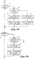
- Figure 2A is a flow diagram illustrating the steps carried out for changing the rate response function at UPL when the sinus rate is determined to be equal to the pacemaker upper pace limit (UPL).
- UPL pacemaker upper pace limit
- Figure 2B is flow diagram indicating the steps taken by the pacemaker of this invention in adapting the rate response function when paced rate is determined to be equal to UPL.
- Figure 3 is a graph showing decision curves and the effect thereon of changes in sensor rate (R).
- Figure 4 is a flow diagram of another embodiment of the pacemaker of this invention wherein rate response function adaptations are made by comparisons between sinus rate and sensor-indicated rate at a plurality of sinus rates within the pacemaker pacing range.
- the terms "sinus rate” or "atrial rate,” as well as the term “measure of the sensed atrial rate,” are used.
- the referenced patent discloses a rate responsive pacemaker using two sensors to obtain a combined or optimum rate response.
- the term "sensor” may refer to one or more sensors used for detecting signals (S) from which an indicated pacing rate (R) may be derived.
- reference to the response curve or slope may mean either the correlation curve of a single sensor, or may refer to the response of combined sensors.
- rate response or “rate response function” is used to indicate the overall correlation of pacing rate (R) as indicated by the sensor input (S).
- R pacing rate
- S sensor input
- a pacemaker preferably an implantable pacemaker 50
- an external programmer 51 the external programmer operating in a known manner to program pacemaker variables.
- a lead 53 is illustrated as connecting to the ventricle, such lead delivering stimulus pulses to the ventricle and also providing sensed patient heartbeat signals to the pacemaker in a known manner.
- a lead 54 is illustrated as connecting the pacemaker to the atrium. In a DDDR pacemaker, lead 54 both delivers atrial stimulus pulses and provides sensed atrial signals back to the pacemaker.
- a single lead is used, and the sensing electrode on lead 54 is in fact a floating electrode on the same lead as extends into the ventricle.
- Leads 55 and 56 are shown connected to sensors S1 and S2 in a patient, for providing rate responsive control parameters.
- the pacemaker is illustrated as having a microprocessor 57, which includes memory for carrying the software of the algorithm of this invention.
- a block 58 is also indicated for signal processing of signals derived from the leads 53, 54 and sensors S1, S2 in a known manner.
- the pacemaker further contains conventional means for generating stimulus pulses, inhibiting on demand, controlling pulse rate, sensing QRS and T wave portions, etc. Also, it is known in the art that in a pacing system which uses QT interval as a rate-indicating parameter, the sensor rate (R) may be obtained during the presence of natural beats by periodically and temporarily overriding the natural rate to deliver pace pulses and thereby determine the Q-T interval.
- interval is the inverse of rate, i.e., pacing interval is the inverse of pacing rate.
- pacing interval is the inverse of pacing rate.
- the invention can be implemented equally with reference to the interval domain, i.e., whereby the pacing interval is controlled by sensors and/or an average atrial interval is determined instead of rate.
- rate and interval are understood to be interchangeable in defining the scope of the invention.
- FIG. 2A there is shown a simplified flow diagram for adaptation of the rate response slope at UPL, when phys rate reaches UPL.
- positive adaptation it is meant that the slope of the rate response curve is adapted, or adjusted so as to more quickly bring pacing rate to UPL, i.e., make the rate response more aggressive in responding to exercise or other demand for increased heart rate.
- negative adaptation means adjusting the response function so that pacing rate is brought up to UPL more slowly, or less aggressively.
- Phys rate is a measure of sensed atrial rate, or sinus rate, in accordance with the reference disclosure of U.S. Application S.N. 07/831,115.
- this subroutine is exited, as no adaptation is called for. However, if the answer is yes, the routine goes to 64, where the difference between UPL and the sensor rate is determined, and compared to a predetermined value delta. The purpose of this logic step is to determine whether the sensor rate is sufficiently far below UPL such that it is not calling for a high enough rate. If the answer is yes, the routine branches to block 66, where the response slope is set to be one step more aggressive. Thus, by making the slope at UPL bring pacing rate up to UPL faster, i.e., more aggressively, the rate response is adjusted to better correspond to the condition where sinus rate equals UPL.
- the pacemaker takes logical steps to prevent further positive adaptation during this clocked day, e.g., until 12 pm. This may be done, for example, by setting a prevent flag before block 62 which would prevent entering this routine until the pacemaker internal clock indicates that another day has arrived, in which case the prevent flag is reset. Alternately, if the comparison at 64 produces a no response, the routine branches to block 70, where the slope is set to be one step less aggressive. Note that the steps taken in block 66 and 70 may be the same, or they may be slightly different to introduce some hysteresis in the adaptation of procedure.
- step 70 may be preceded with a block that determines when (UPL-Sensor Rate) ⁇ delta B, and followed by a block which prevents further negative adaptation until the rate drops delta C below UPL, where delta B and delta C are predetermined rate differentials.
- UPL-Sensor Rate UPL-Sensor Rate
- FIG. 2B there is a simplified block diagram of a routine carried out by the pacemaker of this invention, for introducing negative adaptation of the rate response at UPL.
- This routine is entered during pacing as shown at block 72, where it is determined whether the paced rate, i.e., R, is equal to UPL during pacing. If the answer is no, the routine exits. However, if the answer is yes, the routine branches to block 74, where the pacemaker determines whether the sensor value (S) has changed more than a predetermined interval, designated delta 2. Specifically, the pacer stores the sensor value when the pacing rate (R) initially reaches UPL (S i ).
- the pacemaker compares S with S i to see if S has increased more than delta 2. If the sensor value does not change by the predetermined increment, the routine exits. However, if it does change, this indicates that the rate response was overly aggressive, i.e., pacing rate reached UPL before the patient had reached the point of exercise calling for maximum pacing rate. Correspondingly, if this condition is met, the routine branches to block 76, where the slope is set to be one step less aggressive, i.e., the slope is changed in the direction such that R does not reach UPL as quickly.
- the routine goes to block 78, where a prevent step is taken, similar to block 68, to prevent any additional negative adaptation until the rate (R) drops the predetermined amount, delta 3, below UPL.
- a prevent step is taken, similar to block 68, to prevent any additional negative adaptation until the rate (R) drops the predetermined amount, delta 3, below UPL.
- the slope at URL is only set more aggressively if the pacemaker senses that the sinus rate response, e.g., to exercise, is more aggressive.
- DPR represents the dynamic pacing rate.
- DPR represents the rate at which the pacemaker is set to deliver paces as a function of sensed phys rate, which is a measure of physiological atrial rate. See the referenced application, S.N. 07/831,115.
- LPL lower limit
- the decision curve marked DTL represents the upper limit of the tracking range, i.e., the range within which sensed atrial pulses are tracked for generation of synchronized ventricular stimulus pulses.
- UPL is shown as the upper pacing limit, and represents a programmed upper limit beyond which rate the pacemaker will not generate and deliver stimulus pulses.
- R1, R2 . . . R N representing rates between the lower pacing limit and the upper pacing limit.
- R N represents the last one of the selected rates R1 through R N , through which the phys rate has moved in either an upward or a downward direction.
- phys rate is compared to see whether it is equal to or greater than R N+1 . If yes, meaning that the phys rate has increased beyond the next selected R N , R N is incremented at block 84.
- the phys rate is compared to the sensor rate R, to determine whether the difference is greater than an arbitrarily determined amount delta.
- the routine branches to block 94, where the R curve is adjusted upward at S N (the sensor value corresponding to R N ). In other words, at block 94, the value of R corresponding to S N is increased by one step, making the rate response more aggressive.
- the routine branches to block 96, where the R curve is adjusted downward, or made less aggressive, at S N .
- the routine branches to block 88 where it determines whether phys rate is equal to or less than R N-1 . If yes, the routine branches to block 90, where R N is set equal to R N-1 . Following this, the routine goes to block 92 where Phys Rate - R is measured and compared to see if it is greater than delta. If the answer is yes, the routine branches to block 94, where the R curve is adjusted upward at R N . If the answer is no, the routine branches to block 96, where the R curve is adjusted downward at R N .
- routine goes to block 98, where a limitation is set on the next adjustment. This limitation is the same as the prevent step of blocks 68 and 78 in Figures 2A and 2B, and limits any further change in the curve at this phys rate for a predetermined amount of time.
- routine branches to 2A, which is the routine of Figure 2A, discussed above.
- the algorithm for adjusting the response curve may be simple or complex, within the scope of this invention.
- the entire response function (or curve) may be recalculated based upon the prior values for LRL and URL and the new S/R relation at S N , making certain that R increases monotonically with values of S that indicate a higher pacing rate.
- the routine should check to see that values of R corresponding to higher and lower S values are properly set to greater and lower values.
- the sinus rate is reliable.
- the sinus-tracking feature of this invention can be disabled or bypassed if necessary.
- the tracking feature of this invention can be disabled by appropriate programming. Such programming would suitably involve disabling the negative sinus rate controlled adaptation, and initiating an automatic positive adaptation every eight days, which can be done through programmer 51.
- the pacemaker incorporates logic for recording when the natural sinus does not respond to the onset of exercise properly.
Abstract
Description
- This invention lies in the area of rate responsive cardiac pacemakers and the method of operation of same and, more particularly, dual chamber rate responsive pacemaker systems with means for adjusting the rate response relative to the sensed natural sinus rate so as to optimize tracking of the natural sinus rate as long as it is reliable.
- Dual chamber rate responsive pacemakers are now widely available from pacemaker manufacturers. Such pacemakers may be of many types, including the types designated as DDDR or VDDR. The DDDR pacemaker paces and senses in both chambers, i.e., both the atrium and the ventricle, and has rate responsive (R) backup to provide pacing in the absence of sensed natural beats, or to provide rate responsive ventricular pacing during atrial tachyarrhythmias in the absence of natural ventricular beats. The DDDR pacemaker has a lead that is placed within the atrium to deliver atrial pace pulses, as well as to sense natural atrial (sinus) signals, and a ventricular lead for pacing and sensing in the ventricle. In contrast, the VDDR pacemaker paces only in the ventricle, although it senses in both the atrium and the ventricle. The VDDR pacemaker system may be made simpler by incorporating a single lead, which has a floating atrial electrode for sensing atrial signals, in a known manner. The VDDR pacemaker is indicated for patients who are determined to have a good and reliable sinus rate, so that for a good bit of the anticipated lifetime of the patient, natural atrial signals will be present from which ventricular pace pulses can be tracked, thereby providing synchronized pacing.
- Particularly with respect to the VDDR pacemaker, it is seen that there is an inherent desirability of maximizing use of the sinus rate, i.e., avoiding takeover of the pacing function as long as a good atrial signal is present and sensed. For a rate responsive pacemaker, this leads to the desirability of correlating the rate response as closely as possible to the sensed natural sinus, while still enabling the rate response to take over pacing control when and if the sinus does not accurately reflect cardiac demand. Thus, for example, if a patient develops chronotropic incompetence after implant of a VDDR pacemaker, there must be an ability to switch modes or otherwise enable the sensor response to override the sinus.
- The prior art indicates many schemes for adjusting rate response as a function of exercise. Such schemes include algorithms for ramping up rate upon the onset of exercise, and ramping down rate after exercise, so as to provide a more physiologically natural response to exercise. Such pacemaker systems thus involve predetermined programming for optimizing the pacing response in terms of known optimum responses. It is also known to adjust the rate response as a function of a separate sensor, and to switch to the rate response mode if the atrial rate looks to be unreliable. See, for example, U.S. Patent No. 4,527,568, Rickards, assigned to the same assignee as this invention, where atrial and sensor rate are compared, and the sensor takes over if conditions indicate that this is desirable. However, in pacemakers to date, there is no capability of enabling The rate response function (or algorithm) to track or adapt to the actual sinus rate. Particularly for VDDR mode pacers there is a need to provide a rate response control wherein the sensor-indicated pacing rate is correlated to and tracks just below the sinus rate, so as to optimize sensing of the atrial rate and provide for pacing takeover only when the sinus is unreliable (e.g., atrial tachyarrhythmias) or missing.
- In view of the prior art needs as stated above, it is an object of this invention to provide a rate adaptive pacemaker with the capability of adjusting the sensor/rate relation as a function of sensed sinus rate, particularly for a pacemaker which operates in the VDDR mode. The aim of the improved pacemaker of this invention is to provide a rate response which follows the sensed sinus rate, i.e., the correlation between sensor-indicated pacing rate (R) and the sensor input is adjusted by ongoing comparisons of sinus rate and sensor rate.
- In accordance with the above object, there is provided a rate responsive demand pacemaker, and method of operating same, wherein the sensor-derived rate response is adapted at one or more rates through the pacing range by comparing a measure of the natural sinus rate and the rate response rate (R), and adjusting the response function as a function of that comparison. The comparison may appropriately be made at preselected rates, including the upper pacing limit (UPL) and other rates throughout the pacemaker pacing range. In order to guard against too fast an adjustment of the response function, a limit is provided for limiting the amount and frequency of such adjustments to the rate response function.
- Figure 1 is a block diagram of basic components of a pacemaker in accordance with this invention.
- Figure 2A is a flow diagram illustrating the steps carried out for changing the rate response function at UPL when the sinus rate is determined to be equal to the pacemaker upper pace limit (UPL).
- Figure 2B is flow diagram indicating the steps taken by the pacemaker of this invention in adapting the rate response function when paced rate is determined to be equal to UPL.
- Figure 3 is a graph showing decision curves and the effect thereon of changes in sensor rate (R).
- Figure 4 is a flow diagram of another embodiment of the pacemaker of this invention wherein rate response function adaptations are made by comparisons between sinus rate and sensor-indicated rate at a plurality of sinus rates within the pacemaker pacing range.
- Reference is made to pending application S.N. 07/831,115, filed February 4, 1992, titled "Dual Chamber Pacing System With Dynamic Physiological Tracking and Optimized Synchronous Pacing," assigned to the same assignee. This application, which is incorporated herein by reference, discloses a dual chamber pacemaker operable in a DDDR or VDDR mode, and is background for the present invention. The specification of this application defines a physiological rate, or "phys rate" which is a measure of sensed atrial rate. As defined in the referenced case, such phys rate tracks the sensed sinus rate, but does not include sensed beats which appear to be non-physiological. In this specification as follows, and the claims appended hereto, the terms "sinus rate" or "atrial rate," as well as the term "measure of the sensed atrial rate," are used. Reference is also made to U.S. Patent No. 5,065,759, Begemann et al., issued November 19, 1991 and assigned to the same assignee as this application, which patent is hereby incorporated by reference. The referenced patent discloses a rate responsive pacemaker using two sensors to obtain a combined or optimum rate response. As used herein, the term "sensor" may refer to one or more sensors used for detecting signals (S) from which an indicated pacing rate (R) may be derived. Also, in the following description of the embodiments of this invention, reference to the response curve or slope may mean either the correlation curve of a single sensor, or may refer to the response of combined sensors. The more general term "rate response" or "rate response function" is used to indicate the overall correlation of pacing rate (R) as indicated by the sensor input (S). Reference is made to U.S. Patent No. 5,065,759, for examples of QT and activity "curves," as well as a combined response.
- Referring now to Figure 1, there is shown a schematic representation of a pacer system as utilized in this invention. A pacemaker, preferably an
implantable pacemaker 50, is used with anexternal programmer 51, the external programmer operating in a known manner to program pacemaker variables. Alead 53 is illustrated as connecting to the ventricle, such lead delivering stimulus pulses to the ventricle and also providing sensed patient heartbeat signals to the pacemaker in a known manner. Alead 54 is illustrated as connecting the pacemaker to the atrium. In a DDDR pacemaker,lead 54 both delivers atrial stimulus pulses and provides sensed atrial signals back to the pacemaker. As is understood, for a VDDR pacemaker, a single lead is used, and the sensing electrode onlead 54 is in fact a floating electrode on the same lead as extends into the ventricle.Leads microprocessor 57, which includes memory for carrying the software of the algorithm of this invention. Ablock 58 is also indicated for signal processing of signals derived from theleads - It is further to be noted that the invention is explained by reference to rate. As is well known, interval is the inverse of rate, i.e., pacing interval is the inverse of pacing rate. Thus, it is understood that the invention can be implemented equally with reference to the interval domain, i.e., whereby the pacing interval is controlled by sensors and/or an average atrial interval is determined instead of rate. Thus, rate and interval are understood to be interchangeable in defining the scope of the invention.
- Referring now to Figure 2A, there is shown a simplified flow diagram for adaptation of the rate response slope at UPL, when phys rate reaches UPL. By positive adaptation it is meant that the slope of the rate response curve is adapted, or adjusted so as to more quickly bring pacing rate to UPL, i.e., make the rate response more aggressive in responding to exercise or other demand for increased heart rate. Conversely, negative adaptation means adjusting the response function so that pacing rate is brought up to UPL more slowly, or less aggressively. At
block 62, it is determined whether phys rate is equal to UPL. Phys rate is a measure of sensed atrial rate, or sinus rate, in accordance with the reference disclosure of U.S. Application S.N. 07/831,115. If the answer is no, this subroutine is exited, as no adaptation is called for. However, if the answer is yes, the routine goes to 64, where the difference between UPL and the sensor rate is determined, and compared to a predetermined value delta. The purpose of this logic step is to determine whether the sensor rate is sufficiently far below UPL such that it is not calling for a high enough rate. If the answer is yes, the routine branches to block 66, where the response slope is set to be one step more aggressive. Thus, by making the slope at UPL bring pacing rate up to UPL faster, i.e., more aggressively, the rate response is adjusted to better correspond to the condition where sinus rate equals UPL. Following this, atblock 68, the pacemaker takes logical steps to prevent further positive adaptation during this clocked day, e.g., until 12 pm. This may be done, for example, by setting a prevent flag beforeblock 62 which would prevent entering this routine until the pacemaker internal clock indicates that another day has arrived, in which case the prevent flag is reset. Alternately, if the comparison at 64 produces a no response, the routine branches to block 70, where the slope is set to be one step less aggressive. Note that the steps taken inblock block 70, the routine goes to block 71 where it limits negative adaptation to once a day, i.e., sets a flag to prevent any further negative adaptation until the next day. In a refinement of the routine of Fig. 2A, step 70 may be preceded with a block that determines when (UPL-Sensor Rate) < delta B, and followed by a block which prevents further negative adaptation until the rate drops delta C below UPL, where delta B and delta C are predetermined rate differentials. By this further variation, there is added the feature that no adaptation takes place if the sensor rate lies in the proper range, i.e., UPL-sensor rate is between delta and delta B. - Referring now to Figure 2B, there is a simplified block diagram of a routine carried out by the pacemaker of this invention, for introducing negative adaptation of the rate response at UPL. This routine is entered during pacing as shown at
block 72, where it is determined whether the paced rate, i.e., R, is equal to UPL during pacing. If the answer is no, the routine exits. However, if the answer is yes, the routine branches to block 74, where the pacemaker determines whether the sensor value (S) has changed more than a predetermined interval, designateddelta 2. Specifically, the pacer stores the sensor value when the pacing rate (R) initially reaches UPL (Si). Each cycle thereafter, until R fallsdelta 3 below UPL, the pacemaker compares S with Si to see if S has increased more thandelta 2. If the sensor value does not change by the predetermined increment, the routine exits. However, if it does change, this indicates that the rate response was overly aggressive, i.e., pacing rate reached UPL before the patient had reached the point of exercise calling for maximum pacing rate. Correspondingly, if this condition is met, the routine branches to block 76, where the slope is set to be one step less aggressive, i.e., the slope is changed in the direction such that R does not reach UPL as quickly. Following this, the routine goes to block 78, where a prevent step is taken, similar to block 68, to prevent any additional negative adaptation until the rate (R) drops the predetermined amount,delta 3, below UPL. Note that in this embodiment, the slope at URL is only set more aggressively if the pacemaker senses that the sinus rate response, e.g., to exercise, is more aggressive. - Referring now to Figures 3 and 4, there is shown another embodiment of this invention for providing adjustments or adaptation to the rate response function at rates other than UPL, i.e., substantially throughout the pacing range available to the pacemaker. Referring to Figure 3, there are shown curves of decision rates versus phys rate. The lower line, designated DPR, represents the dynamic pacing rate. DPR represents the rate at which the pacemaker is set to deliver paces as a function of sensed phys rate, which is a measure of physiological atrial rate. See the referenced application, S.N. 07/831,115. Thus, as indicated, DPR is set at a lower limit (LPL) for all sensed rates up to a certain point, after which DPR increases linearly with phys rate. When the sensor calls for a higher or lower rate, the horizontal portion of the DPR curve moves up or down, as indicated by the arrows. The decision curve marked DTL, for dynamic tracking limit, represents the upper limit of the tracking range, i.e., the range within which sensed atrial pulses are tracked for generation of synchronized ventricular stimulus pulses. UPL is shown as the upper pacing limit, and represents a programmed upper limit beyond which rate the pacemaker will not generate and deliver stimulus pulses. Also indicated schematically are arbitrary rates R₁, R₂ . . . RN representing rates between the lower pacing limit and the upper pacing limit. These rates are utilized in the flow diagram of Figure 4.
- Referring now to Figure 4, in this embodiment of the invention, the routine first reads RN at
block 80. RN represents the last one of the selected rates R₁ through RN, through which the phys rate has moved in either an upward or a downward direction. Atstep 82, phys rate is compared to see whether it is equal to or greater than RN+1. If yes, meaning that the phys rate has increased beyond the next selected RN, RN is incremented atblock 84. Following this, atstep 86, the phys rate is compared to the sensor rate R, to determine whether the difference is greater than an arbitrarily determined amount delta. If yes, meaning that R has not followed as closely as delta to phys rate, the routine branches to block 94, where the R curve is adjusted upward at SN (the sensor value corresponding to RN). In other words, atblock 94, the value of R corresponding to SN is increased by one step, making the rate response more aggressive. Returning to 86, if the comparison results in a no response, the routine branches to block 96, where the R curve is adjusted downward, or made less aggressive, at SN. - Returning to block 82, if the comparison results in a no response, the routine branches to block 88 where it determines whether phys rate is equal to or less than RN-1. If yes, the routine branches to block 90, where RN is set equal to RN-1. Following this, the routine goes to block 92 where Phys Rate - R is measured and compared to see if it is greater than delta. If the answer is yes, the routine branches to block 94, where the R curve is adjusted upward at RN. If the answer is no, the routine branches to block 96, where the R curve is adjusted downward at RN.
- Following either adjustment at
block blocks - The algorithm for adjusting the response curve may be simple or complex, within the scope of this invention. Thus, if an adjustment is made at RN, the entire response function (or curve) may be recalculated based upon the prior values for LRL and URL and the new S/R relation at SN, making certain that R increases monotonically with values of S that indicate a higher pacing rate. In any event, when the value of R is changed at any point, the routine should check to see that values of R corresponding to higher and lower S values are properly set to greater and lower values.
- As noted above, for a VDDR pacemaker it is assumed that the sinus rate is reliable. In order to safeguard against a situation where the sinus rate becomes unreliable after implantation, it is necessary to provide that the sinus-tracking feature of this invention can be disabled or bypassed if necessary. If the attending physician observes a condition such as chronotropic incompetence, the tracking feature of this invention can be disabled by appropriate programming. Such programming would suitably involve disabling the negative sinus rate controlled adaptation, and initiating an automatic positive adaptation every eight days, which can be done through
programmer 51. Alternately, the pacemaker incorporates logic for recording when the natural sinus does not respond to the onset of exercise properly. For example, by using an activity-based sensor which reliably indicates exercise episodes, and comparing the sensor indications with sinus rate during such episodes, it can be determined whether the sinus rate is reliable. If it is found to be unreliable, then the routines of Figure 2A and/or Figure 4 are disabled.
Claims (14)
- A rate responsive demand pacemaker (50) having a pulse generator for generating and delivering stimulus pulses, rate sense means for sensing natural beats and obtaining a measure of the rate of said natural beats, a rate control for controlling the rate of delivery of stimulus pulses by said pulse generator, rate responsive means (S₁, S₂, 58) for obtaining sensor signals indicative of desired pacing rate and for generating therefrom sensor rate signals (R) in accordance with a rate response function which is a function of said sensor signals over a desired pacing range, said rate control circuit controlling said rate in accordance with R in the absence of sensed natural beats, characterized by first comparing means (62) for comparing said measure of said natural beat rate and R at at least one predetermined pacing rate, and adjust means (64, 66, 70) operative during detection of natural beats for adjusting said rate response function as a function of said first comparison.
- The pacemaker as described in claim 1, further comprising limit means (68, 71) for limiting said adjusting.
- The pacemaker as described in claim 1, wherein said adjusting comprises adjusting the slope of said rate response at a predetermined rate.
- The pacemaker as described in claim 1, wherein said pacemaker is adapted to operate in the VDD mode and said detected natural beats are sinus beats.
- The pacemaker as described in claim 4, comprising phys means for determining a phys rate based on said natural sinus beats, and wherein said first comparison compares said phys rate and R (82).
- The pacemaker as described in claim 1, wherein said first comparing means is operative when said natural rate equals a predetermined upper pacing limit (UPL).
- The pacemaker as described in claim 6, wherein said first comparing means comprises first determining means for determining whether said sensor rate (R) is less than UPL by more than a first predetermined increment (64), and first changing means for changing said rate response function so that R reaches UPL more aggressively when said sensor rate (R) is less than UPL by more than said increment (66).
- The pacemaker as described in claim 7, wherein said limit means limits adaptation of said rate curve to one predetermined step per day (68).
- The pacemaker as described in claim 7, wherein said first comparing means comprises second determining means for determining when the difference between UPL and the sensor rate is less than a second predetermined increment, and second changing means for changing said curve to be less aggressive when said difference is less than said second predetermined increment (70).
- The pacemaker as described in claim 1, further comprising second comparing means (72) operative following delivery of pacing pulses for determining when the pacing rate is equal to or greater than a predetermined UPL, combined with means operative when the pacemaker is pacing and when the pacing rate is determined to be equal to or greater than UPL for determining if said rate response is too aggressive and for reducing the aggressiveness of said rate response if it is determined to be too aggressive (74, 76).
- The pacemaker as described in claim 4, further comprising intermediate comparing means for comparing said measure of the rate of sensed sinus heartbeats with R at at least about one predetermined rate below a predetermined UPL (82), and intermediate change means for changing said rate response at said about one rate as a function of said intermediate comparison (94, 96).
- The pacemaker as described in claim 11, wherein said intermediate comparison means comprises means for comparing the sensed natural rate with R at a plurality of rates, and means for adjusting said rate response as a function of said comparisons.
- A pacemaker (50) having a pulse generator for generating and delivering stimulus pulses, rate sense means for sensing natural beats and obtaining a measure of the rate of said natural beats, a rate control for controlling the rate of delivery of stimulus pulses by said pulse generator, rate responsive means for obtaining sensor signals indicative of desired pacing rate and for generating therefrom sensor rate signals (R) in accordance with a rate response function which is a function of said sensor signals over a desired pacing range, said rate control controlling said rate as a function of R in the absence of sensed natural beats, further comprising rate response adjust means for automatically adjusting said rate response function as a function of sensed sinus rate so as to track said sensed sinus rate (82, 86, 88, 92, 94, 96), and means for limiting said adjusting to long term adjustments (98).
- The pacemaker as described in claim 13, comprising means for determining when the natural sinus rate does not increase under cardiac conditions calling for an increased rate, and for inhibiting said adjusting of the rate response function over at least a predetermined rate range following such a determination.
Applications Claiming Priority (2)
| Application Number | Priority Date | Filing Date | Title |
|---|---|---|---|
| US49181 | 1993-04-19 | ||
| US08/049,181 US5350409A (en) | 1993-04-19 | 1993-04-19 | Rate adaptive pacemaker with adjustment of sensor rate as a function of sensed sinus rate |
Publications (3)
| Publication Number | Publication Date |
|---|---|
| EP0621055A2 true EP0621055A2 (en) | 1994-10-26 |
| EP0621055A3 EP0621055A3 (en) | 1997-05-07 |
| EP0621055B1 EP0621055B1 (en) | 2000-11-02 |
Family
ID=21958457
Family Applications (1)
| Application Number | Title | Priority Date | Filing Date |
|---|---|---|---|
| EP94104795A Expired - Lifetime EP0621055B1 (en) | 1993-04-19 | 1994-03-25 | Rate adaptive pacemaker with adjustment of sensor rate as a function of sensed sinus rate |
Country Status (3)
| Country | Link |
|---|---|
| US (1) | US5350409A (en) |
| EP (1) | EP0621055B1 (en) |
| DE (1) | DE69426214T2 (en) |
Families Citing this family (36)
| Publication number | Priority date | Publication date | Assignee | Title |
|---|---|---|---|---|
| WO1995009661A2 (en) * | 1993-09-29 | 1995-04-13 | Medtronic, Inc. | Sinus preference method and apparatus for cardiac pacemakers |
| US5540727A (en) * | 1994-11-15 | 1996-07-30 | Cardiac Pacemakers, Inc. | Method and apparatus to automatically optimize the pacing mode and pacing cycle parameters of a dual chamber pacemaker |
| US5713929A (en) * | 1996-05-03 | 1998-02-03 | Medtronic, Inc. | Arrhythmia and fibrillation prevention pacemaker using ratchet up and decay modes of operation |
| US5800466A (en) * | 1997-04-14 | 1998-09-01 | Sulzer Intermedics Inc. | Dynamic atrial detection sensitivity control in an implantable medical cardiac simulator |
| US5735881A (en) * | 1997-04-14 | 1998-04-07 | Sulzer Intermedics Inc. | Variable atrail blanking period in an implantable medical device |
| US5843133A (en) * | 1997-04-14 | 1998-12-01 | Sulzer Intermedics Inc. | Dynamic bandwidth control in an implantable medical cardiac stimulator |
| US5772691A (en) * | 1997-04-14 | 1998-06-30 | Sulzer Intermedics Inc. | Implantable cardiac stimulator with polarity detection for detecting ectopic beats |
| US5792200A (en) * | 1997-04-28 | 1998-08-11 | Sulzer Intermedics Inc. | Adaptive mode switching in a rate-adaptive pacemaker and hysteresis for mode switching |
| SE9901195D0 (en) | 1999-03-31 | 1999-03-31 | Pacesetter Ab | A rate adaptive pacemaker |
| US7203535B1 (en) | 1999-04-01 | 2007-04-10 | Cardiac Pacemakers, Inc. | System and method for classifying tachycardia arrhythmias having 1:1 atrial-to-ventricular rhythms |
| US8064997B2 (en) | 1999-05-21 | 2011-11-22 | Cardiac Pacemakers, Inc. | Method and apparatus for treating irregular ventricular contractions such as during atrial arrhythmia |
| US6351669B1 (en) | 1999-05-21 | 2002-02-26 | Cardiac Pacemakers, Inc. | Cardiac rhythm management system promoting atrial pacing |
| US7062325B1 (en) | 1999-05-21 | 2006-06-13 | Cardiac Pacemakers Inc | Method and apparatus for treating irregular ventricular contractions such as during atrial arrhythmia |
| US7181278B2 (en) * | 1999-05-21 | 2007-02-20 | Cardiac Pacemakers, Inc. | Apparatus and method for ventricular rate regularization |
| US7142918B2 (en) | 2000-12-26 | 2006-11-28 | Cardiac Pacemakers, Inc. | Apparatus and method for pacing mode switching during atrial tachyarrhythmias |
| US7212860B2 (en) | 1999-05-21 | 2007-05-01 | Cardiac Pacemakers, Inc. | Apparatus and method for pacing mode switching during atrial tachyarrhythmias |
| US6501988B2 (en) | 2000-12-26 | 2002-12-31 | Cardiac Pacemakers Inc. | Apparatus and method for ventricular rate regularization with biventricular sensing |
| US6430438B1 (en) | 1999-05-21 | 2002-08-06 | Cardiac Pacemakers, Inc. | Cardiac rhythm management system with atrial shock timing optimization |
| US6285907B1 (en) | 1999-05-21 | 2001-09-04 | Cardiac Pacemakers, Inc. | System providing ventricular pacing and biventricular coordination |
| US7039461B1 (en) | 2000-05-13 | 2006-05-02 | Cardiac Pacemakers, Inc. | Cardiac pacing system for prevention of ventricular fibrillation and ventricular tachycardia episode |
| US6501987B1 (en) | 2000-05-26 | 2002-12-31 | Cardiac Pacemakers, Inc. | Rate smoothing control |
| US7239914B2 (en) * | 2000-05-13 | 2007-07-03 | Cardiac Pacemakers, Inc. | Rate smoothing control |
| US8512220B2 (en) | 2000-05-26 | 2013-08-20 | Cardiac Pacemakers, Inc. | Rate smoothing control |
| US6424865B1 (en) | 2000-07-13 | 2002-07-23 | Cardiac Pacemakers, Inc. | Ventricular conduction delay trending system and method |
| US6829504B1 (en) | 2000-09-14 | 2004-12-07 | Cardiac Pacemakers, Inc. | System and method for preventing recurrence of atrial tachyarrhythmia |
| US6512951B1 (en) | 2000-09-14 | 2003-01-28 | Cardiac Pacemakers, Inc. | Delivery of atrial defibrillation shock based on estimated QT interval |
| US6904315B2 (en) | 2000-12-14 | 2005-06-07 | Medtronic, Inc. | Atrial aware VVI: a method for atrial synchronous ventricular (VDD/R) pacing using the subcutaneous electrode array and a standard pacing lead |
| US6957100B2 (en) | 2000-12-26 | 2005-10-18 | Cardiac Pacemakers, Inc. | Method and system for display of cardiac event intervals in a resynchronization pacemaker |
| US20020087198A1 (en) * | 2000-12-29 | 2002-07-04 | Kramer Andrew P. | Apparatus and method for ventricular rate regularization |
| US7050854B2 (en) * | 2002-06-24 | 2006-05-23 | Cardiac Pacemakers, Inc. | Calibration of adaptive-rate pacing using intrinsic chronotropic response |
| US20090149904A1 (en) | 2007-12-11 | 2009-06-11 | Cardiac Pacemakers, Inc. | Lv unipolar sensing or pacing vector |
| US20090157133A1 (en) | 2007-12-13 | 2009-06-18 | Cardiac Pacemakers, Inc. | Supraventricular tachy sensing vector |
| WO2010099424A1 (en) * | 2009-02-27 | 2010-09-02 | Medtronic, Inc. | A system and method for conditional biventricular pacing |
| US8996101B2 (en) * | 2012-03-12 | 2015-03-31 | Medtronic, Inc. | Heart sound sensing to reduce inappropriate tachyarrhythmia therapy |
| US10434317B2 (en) | 2016-10-31 | 2019-10-08 | Cardiac Pacemakers, Inc. | Systems and methods for activity level pacing |
| US10617874B2 (en) | 2016-10-31 | 2020-04-14 | Cardiac Pacemakers, Inc. | Systems and methods for activity level pacing |
Citations (6)
| Publication number | Priority date | Publication date | Assignee | Title |
|---|---|---|---|---|
| US4313442A (en) * | 1980-07-21 | 1982-02-02 | Cardiac Pacemakers, Inc. | Atrial rate sensitive cardiac pacer apparatus |
| EP0191404A1 (en) * | 1985-02-04 | 1986-08-20 | Telectronics N.V. | Activity sensor for pacemaker control |
| EP0324598A2 (en) * | 1988-01-14 | 1989-07-19 | Stuart Charles Webb | Rate-responsive pacemaker |
| WO1989006990A1 (en) * | 1988-02-05 | 1989-08-10 | Siemens Aktiengesellschaft | Control circuit for adapting the stimulation frequency of a heart pace-maker to patient effort |
| EP0448193A1 (en) * | 1990-03-20 | 1991-09-25 | Telectronics N.V. | A metabolic demand driven rate-responsive pacemaker |
| US5065759A (en) * | 1990-08-30 | 1991-11-19 | Vitatron Medical B.V. | Pacemaker with optimized rate responsiveness and method of rate control |
Family Cites Families (5)
| Publication number | Priority date | Publication date | Assignee | Title |
|---|---|---|---|---|
| US4527568A (en) * | 1983-12-27 | 1985-07-09 | Vitafin N.V. | Dual chamber pacer with alternative rate adaptive means and method |
| EP0215731B1 (en) * | 1985-09-17 | 1992-12-30 | BIOTRONIK Mess- und Therapiegeräte GmbH & Co Ingenieurbüro Berlin | Heart stimulator |
| US4856523A (en) * | 1987-10-08 | 1989-08-15 | Siemens-Pacesetter, Inc. | Rate-responsive pacemaker with automatic mode switching and/or variable hysteresis rate |
| US4855524A (en) * | 1987-11-10 | 1989-08-08 | Mobil Oil Corporation | Process for combining the operation of oligomerization reactors containing a zeolite oligomerization catalyst |
| US5052388A (en) * | 1989-12-22 | 1991-10-01 | Medtronic, Inc. | Method and apparatus for implementing activity sensing in a pulse generator |
-
1993
- 1993-04-19 US US08/049,181 patent/US5350409A/en not_active Expired - Lifetime
-
1994
- 1994-03-25 DE DE69426214T patent/DE69426214T2/en not_active Expired - Lifetime
- 1994-03-25 EP EP94104795A patent/EP0621055B1/en not_active Expired - Lifetime
Patent Citations (6)
| Publication number | Priority date | Publication date | Assignee | Title |
|---|---|---|---|---|
| US4313442A (en) * | 1980-07-21 | 1982-02-02 | Cardiac Pacemakers, Inc. | Atrial rate sensitive cardiac pacer apparatus |
| EP0191404A1 (en) * | 1985-02-04 | 1986-08-20 | Telectronics N.V. | Activity sensor for pacemaker control |
| EP0324598A2 (en) * | 1988-01-14 | 1989-07-19 | Stuart Charles Webb | Rate-responsive pacemaker |
| WO1989006990A1 (en) * | 1988-02-05 | 1989-08-10 | Siemens Aktiengesellschaft | Control circuit for adapting the stimulation frequency of a heart pace-maker to patient effort |
| EP0448193A1 (en) * | 1990-03-20 | 1991-09-25 | Telectronics N.V. | A metabolic demand driven rate-responsive pacemaker |
| US5065759A (en) * | 1990-08-30 | 1991-11-19 | Vitatron Medical B.V. | Pacemaker with optimized rate responsiveness and method of rate control |
Also Published As
| Publication number | Publication date |
|---|---|
| US5350409A (en) | 1994-09-27 |
| DE69426214T2 (en) | 2001-05-17 |
| DE69426214D1 (en) | 2000-12-07 |
| EP0621055A3 (en) | 1997-05-07 |
| EP0621055B1 (en) | 2000-11-02 |
Similar Documents
| Publication | Publication Date | Title |
|---|---|---|
| US5350409A (en) | Rate adaptive pacemaker with adjustment of sensor rate as a function of sensed sinus rate | |
| EP0596598B1 (en) | Cardiac rhythm management device with automatic optimization of performance related pacing parameters | |
| US6823214B1 (en) | Self-calibrating rate-adaptive pacemaker | |
| EP0652029B1 (en) | Rate adaptive dual chamber pacing system with automatic adjustment of operating parameters for minimizing sensor-sinus competition | |
| US5814087A (en) | Rate responsive pacemaker adapted to adjust lower rate limit according to monitored patient blood temperature | |
| US5814077A (en) | Pacemaker and method of operating same that provides functional atrial cardiac pacing with ventricular support | |
| EP0545967B1 (en) | Rate controlled pacemaker system using ar interval for rate control | |
| US5374282A (en) | Automatic sensitivity adjust for cardiac pacemakers | |
| US6990375B2 (en) | Adjustment of the breakpoint of the rate response curve based on minute ventilation values | |
| US5447525A (en) | Pacemaker which adapts to minimize current drain and provide desired capture safety margin | |
| US5549649A (en) | Programmable pacemaker including an atrial rate filter for deriving a filtered atrial rate used for switching pacing modes | |
| US5480414A (en) | Method and apparatus for controlling pacemaker during automatic capture detection | |
| US5676686A (en) | Pacemaker with vasovagal syncope detection | |
| US5609613A (en) | Control of pacing rate in dual-chamber, rate-adaptive pacemakers | |
| WO1993016756A1 (en) | Cardiac pacemaker with hysteresis behavior | |
| US6839593B1 (en) | Rate-adaptive therapy with automatic limiting of maximum pacing rate | |
| US6408209B1 (en) | Enslaved active implantable medical device protected from the effects of brady-and/or tachy-dependent extrasystoles | |
| US6339724B1 (en) | Method of controlling the stimulation amplitude of a cardiologic implant | |
| EP1374947A2 (en) | Pacemaker with vasovagal syncope detection | |
| EP0148486B1 (en) | Improved rate adaptive pacemaker apparatus | |
| US7027865B2 (en) | Pacemaker with vasovagal syncope detection and therapy | |
| US7085602B2 (en) | Implantable bi-ventricular stimulation device and system, and bi-ventricular stimulation and sensing method | |
| US20080281373A1 (en) | Implantable Heart Stimulator and Method for Operation Thereof |
Legal Events
| Date | Code | Title | Description |
|---|---|---|---|
| PUAI | Public reference made under article 153(3) epc to a published international application that has entered the european phase |
Free format text: ORIGINAL CODE: 0009012 |
|
| AK | Designated contracting states |
Kind code of ref document: A2 Designated state(s): DE FR GB IT NL SE |
|
| PUAL | Search report despatched |
Free format text: ORIGINAL CODE: 0009013 |
|
| AK | Designated contracting states |
Kind code of ref document: A3 Designated state(s): DE FR GB IT NL SE |
|
| 17P | Request for examination filed |
Effective date: 19970625 |
|
| 17Q | First examination report despatched |
Effective date: 19990222 |
|
| GRAG | Despatch of communication of intention to grant |
Free format text: ORIGINAL CODE: EPIDOS AGRA |
|
| 17Q | First examination report despatched |
Effective date: 19990222 |
|
| GRAG | Despatch of communication of intention to grant |
Free format text: ORIGINAL CODE: EPIDOS AGRA |
|
| GRAH | Despatch of communication of intention to grant a patent |
Free format text: ORIGINAL CODE: EPIDOS IGRA |
|
| GRAH | Despatch of communication of intention to grant a patent |
Free format text: ORIGINAL CODE: EPIDOS IGRA |
|
| GRAA | (expected) grant |
Free format text: ORIGINAL CODE: 0009210 |
|
| AK | Designated contracting states |
Kind code of ref document: B1 Designated state(s): DE FR GB IT NL SE |
|
| ITF | It: translation for a ep patent filed |
Owner name: BUGNION S.P.A. |
|
| REF | Corresponds to: |
Ref document number: 69426214 Country of ref document: DE Date of ref document: 20001207 |
|
| ET | Fr: translation filed | ||
| PLBE | No opposition filed within time limit |
Free format text: ORIGINAL CODE: 0009261 |
|
| STAA | Information on the status of an ep patent application or granted ep patent |
Free format text: STATUS: NO OPPOSITION FILED WITHIN TIME LIMIT |
|
| 26N | No opposition filed | ||
| REG | Reference to a national code |
Ref country code: GB Ref legal event code: IF02 |
|
| PGFP | Annual fee paid to national office [announced via postgrant information from national office to epo] |
Ref country code: GB Payment date: 20070202 Year of fee payment: 14 |
|
| PGFP | Annual fee paid to national office [announced via postgrant information from national office to epo] |
Ref country code: NL Payment date: 20070214 Year of fee payment: 14 |
|
| PGFP | Annual fee paid to national office [announced via postgrant information from national office to epo] |
Ref country code: SE Payment date: 20070305 Year of fee payment: 14 |
|
| PGFP | Annual fee paid to national office [announced via postgrant information from national office to epo] |
Ref country code: IT Payment date: 20080319 Year of fee payment: 15 |
|
| EUG | Se: european patent has lapsed | ||
| GBPC | Gb: european patent ceased through non-payment of renewal fee |
Effective date: 20080325 |
|
| PG25 | Lapsed in a contracting state [announced via postgrant information from national office to epo] |
Ref country code: NL Free format text: LAPSE BECAUSE OF NON-PAYMENT OF DUE FEES Effective date: 20081001 |
|
| NLV4 | Nl: lapsed or anulled due to non-payment of the annual fee |
Effective date: 20081001 |
|
| PG25 | Lapsed in a contracting state [announced via postgrant information from national office to epo] |
Ref country code: SE Free format text: LAPSE BECAUSE OF NON-PAYMENT OF DUE FEES Effective date: 20080326 |
|
| PG25 | Lapsed in a contracting state [announced via postgrant information from national office to epo] |
Ref country code: GB Free format text: LAPSE BECAUSE OF NON-PAYMENT OF DUE FEES Effective date: 20080325 |
|
| PG25 | Lapsed in a contracting state [announced via postgrant information from national office to epo] |
Ref country code: IT Free format text: LAPSE BECAUSE OF NON-PAYMENT OF DUE FEES Effective date: 20090325 |
|
| PGFP | Annual fee paid to national office [announced via postgrant information from national office to epo] |
Ref country code: FR Payment date: 20120406 Year of fee payment: 19 |
|
| PGFP | Annual fee paid to national office [announced via postgrant information from national office to epo] |
Ref country code: DE Payment date: 20120328 Year of fee payment: 19 |
|
| REG | Reference to a national code |
Ref country code: FR Ref legal event code: ST Effective date: 20131129 |
|
| REG | Reference to a national code |
Ref country code: DE Ref legal event code: R119 Ref document number: 69426214 Country of ref document: DE Effective date: 20131001 |
|
| PG25 | Lapsed in a contracting state [announced via postgrant information from national office to epo] |
Ref country code: FR Free format text: LAPSE BECAUSE OF NON-PAYMENT OF DUE FEES Effective date: 20130402 Ref country code: DE Free format text: LAPSE BECAUSE OF NON-PAYMENT OF DUE FEES Effective date: 20131001 |