EP0621145A1 - Knuckle bracket - Google Patents
Knuckle bracket Download PDFInfo
- Publication number
- EP0621145A1 EP0621145A1 EP94201792A EP94201792A EP0621145A1 EP 0621145 A1 EP0621145 A1 EP 0621145A1 EP 94201792 A EP94201792 A EP 94201792A EP 94201792 A EP94201792 A EP 94201792A EP 0621145 A1 EP0621145 A1 EP 0621145A1
- Authority
- EP
- European Patent Office
- Prior art keywords
- bracket
- support pieces
- knuckle
- backrest portion
- shock absorber
- Prior art date
- Legal status (The legal status is an assumption and is not a legal conclusion. Google has not performed a legal analysis and makes no representation as to the accuracy of the status listed.)
- Granted
Links
- 230000003014 reinforcing effect Effects 0.000 claims abstract description 23
- 230000035939 shock Effects 0.000 claims abstract description 19
- 239000006096 absorbing agent Substances 0.000 claims abstract description 18
- 230000002787 reinforcement Effects 0.000 claims description 2
- 238000005452 bending Methods 0.000 description 2
- 230000002093 peripheral effect Effects 0.000 description 2
- 238000010276 construction Methods 0.000 description 1
- 230000000694 effects Effects 0.000 description 1
Images

Classifications
-
- B—PERFORMING OPERATIONS; TRANSPORTING
- B60—VEHICLES IN GENERAL
- B60G—VEHICLE SUSPENSION ARRANGEMENTS
- B60G15/00—Resilient suspensions characterised by arrangement, location or type of combined spring and vibration damper, e.g. telescopic type
- B60G15/02—Resilient suspensions characterised by arrangement, location or type of combined spring and vibration damper, e.g. telescopic type having mechanical spring
- B60G15/06—Resilient suspensions characterised by arrangement, location or type of combined spring and vibration damper, e.g. telescopic type having mechanical spring and fluid damper
- B60G15/07—Resilient suspensions characterised by arrangement, location or type of combined spring and vibration damper, e.g. telescopic type having mechanical spring and fluid damper the damper being connected to the stub axle and the spring being arranged around the damper
-
- B—PERFORMING OPERATIONS; TRANSPORTING
- B60—VEHICLES IN GENERAL
- B60G—VEHICLE SUSPENSION ARRANGEMENTS
- B60G13/00—Resilient suspensions characterised by arrangement, location or type of vibration dampers
- B60G13/001—Arrangements for attachment of dampers
- B60G13/005—Arrangements for attachment of dampers characterised by the mounting on the axle or suspension arm of the damper unit
- B60G13/006—Arrangements for attachment of dampers characterised by the mounting on the axle or suspension arm of the damper unit on the stub axle
-
- F—MECHANICAL ENGINEERING; LIGHTING; HEATING; WEAPONS; BLASTING
- F16—ENGINEERING ELEMENTS AND UNITS; GENERAL MEASURES FOR PRODUCING AND MAINTAINING EFFECTIVE FUNCTIONING OF MACHINES OR INSTALLATIONS; THERMAL INSULATION IN GENERAL
- F16B—DEVICES FOR FASTENING OR SECURING CONSTRUCTIONAL ELEMENTS OR MACHINE PARTS TOGETHER, e.g. NAILS, BOLTS, CIRCLIPS, CLAMPS, CLIPS OR WEDGES; JOINTS OR JOINTING
- F16B2/00—Friction-grip releasable fastenings
- F16B2/02—Clamps, i.e. with gripping action effected by positive means other than the inherent resistance to deformation of the material of the fastening
- F16B2/06—Clamps, i.e. with gripping action effected by positive means other than the inherent resistance to deformation of the material of the fastening external, i.e. with contracting action
-
- F—MECHANICAL ENGINEERING; LIGHTING; HEATING; WEAPONS; BLASTING
- F16—ENGINEERING ELEMENTS AND UNITS; GENERAL MEASURES FOR PRODUCING AND MAINTAINING EFFECTIVE FUNCTIONING OF MACHINES OR INSTALLATIONS; THERMAL INSULATION IN GENERAL
- F16L—PIPES; JOINTS OR FITTINGS FOR PIPES; SUPPORTS FOR PIPES, CABLES OR PROTECTIVE TUBING; MEANS FOR THERMAL INSULATION IN GENERAL
- F16L3/00—Supports for pipes, cables or protective tubing, e.g. hangers, holders, clamps, cleats, clips, brackets
- F16L3/08—Supports for pipes, cables or protective tubing, e.g. hangers, holders, clamps, cleats, clips, brackets substantially surrounding the pipe, cable or protective tubing
- F16L3/12—Supports for pipes, cables or protective tubing, e.g. hangers, holders, clamps, cleats, clips, brackets substantially surrounding the pipe, cable or protective tubing comprising a member substantially surrounding the pipe, cable or protective tubing
-
- B—PERFORMING OPERATIONS; TRANSPORTING
- B60—VEHICLES IN GENERAL
- B60G—VEHICLE SUSPENSION ARRANGEMENTS
- B60G2202/00—Indexing codes relating to the type of spring, damper or actuator
- B60G2202/30—Spring/Damper and/or actuator Units
- B60G2202/31—Spring/Damper and/or actuator Units with the spring arranged around the damper, e.g. MacPherson strut
- B60G2202/312—The spring being a wound spring
-
- B—PERFORMING OPERATIONS; TRANSPORTING
- B60—VEHICLES IN GENERAL
- B60G—VEHICLE SUSPENSION ARRANGEMENTS
- B60G2204/00—Indexing codes related to suspensions per se or to auxiliary parts
- B60G2204/10—Mounting of suspension elements
- B60G2204/12—Mounting of springs or dampers
- B60G2204/129—Damper mount on wheel suspension or knuckle
-
- B—PERFORMING OPERATIONS; TRANSPORTING
- B60—VEHICLES IN GENERAL
- B60G—VEHICLE SUSPENSION ARRANGEMENTS
- B60G2204/00—Indexing codes related to suspensions per se or to auxiliary parts
- B60G2204/40—Auxiliary suspension parts; Adjustment of suspensions
- B60G2204/43—Fittings, brackets or knuckles
- B60G2204/4302—Fittings, brackets or knuckles for fixing suspension arm on the vehicle body or chassis
-
- B—PERFORMING OPERATIONS; TRANSPORTING
- B60—VEHICLES IN GENERAL
- B60G—VEHICLE SUSPENSION ARRANGEMENTS
- B60G2204/00—Indexing codes related to suspensions per se or to auxiliary parts
- B60G2204/40—Auxiliary suspension parts; Adjustment of suspensions
- B60G2204/43—Fittings, brackets or knuckles
- B60G2204/4304—Bracket for lower cylinder mount of McPherson strut
-
- B—PERFORMING OPERATIONS; TRANSPORTING
- B60—VEHICLES IN GENERAL
- B60G—VEHICLE SUSPENSION ARRANGEMENTS
- B60G2206/00—Indexing codes related to the manufacturing of suspensions: constructional features, the materials used, procedures or tools
- B60G2206/01—Constructional features of suspension elements, e.g. arms, dampers, springs
- B60G2206/40—Constructional features of dampers and/or springs
-
- Y—GENERAL TAGGING OF NEW TECHNOLOGICAL DEVELOPMENTS; GENERAL TAGGING OF CROSS-SECTIONAL TECHNOLOGIES SPANNING OVER SEVERAL SECTIONS OF THE IPC; TECHNICAL SUBJECTS COVERED BY FORMER USPC CROSS-REFERENCE ART COLLECTIONS [XRACs] AND DIGESTS
- Y10—TECHNICAL SUBJECTS COVERED BY FORMER USPC
- Y10S—TECHNICAL SUBJECTS COVERED BY FORMER USPC CROSS-REFERENCE ART COLLECTIONS [XRACs] AND DIGESTS
- Y10S248/00—Supports
- Y10S248/916—Mechanical expedients, e.g. in supports
Definitions
- the present invention relates to a knuckle bracket for use in mounting a strut type shock absorber which is disposed between a vehicle body and a wheel in order to support the vehicle body and absorb energy such as vibration from the road surface.
- a strut type shock absorber comprises an outer shell and a shock absorber inserted into the outer shell.
- a lower portion of the outer shell is connected to a wheel of a vehicle while being supported by a knuckle bracket.
- Known knuckle brackets of this type are disclosed in Japanese Utility Model Publication No. 13790/86, U.S. Patent No. 4,491,339 and Japanese Patent Laid Open No. 160442/81, and the structure shown in Fig. 4 attached hereto is a typical prior art structure.
- the knuckle bracket illustrated in Fig. 4 and indicated at A comprises an outer bracket 1 and an inner bracket 2.
- the outer bracket 1 comprises a loop portion 4 which extends around an outer shell 3 and a pair of clamp portions 5, 5 extending in parallel from the loop portion 4.
- the inner bracket 2 comprises a curved backrest portion 6 which is in abutment with the outer shell 3 and a pair of support pieces 7, 7 extending in parallel from the backrest portion 6.
- a lower portion of the outer shell 3 with a shock absorber 8 inserted therein is located within the loop portion 4 of the outer bracket 1, and the support pieces 7, 7 of the inner bracket 2 are clamped by the clamp portions 5, 5 of the outer bracket 1 while the backrest portion 6 of the inner bracket 2 is kept in abutment with the outer shell 3.
- the clamp portions 5 and the support pieces 7 are clamped together with bolts inserted into bolt holes 9.
- DE-U-8517424 proposes modifying the above-described known knuckle bracket by incorporating an outwardly-bent extension to the top of the backrest portion.
- the support pieces are extended upwards to meet the sides of the backrest extension.
- a knuckle bracket for mounting on a cylindrical item such as a shock absorber
- said knuckle bracket comprising: an outer bracket having a loop portion, for receiving therein the cylindrical item, and a pair of clamp portions extending substantially in parallel from said loop portion; an inner bracket having a curved backrest portion and a pair of support pieces extending substantially in parallel from said backrest portion, said support pieces being inserted between and clampable to said clamp portions of said outer bracket and said backrest portion being abutable against the cylindrical item; and a reinforcing bracket which comprises a first wall which (i) extends at least across the gap between said support pieces and (ii) acts as a reinforcement to resist splaying apart of said support pieces; characterized in that said first wall is located between the ends of said inner bracket and is generally parallel to said backrest portion.
- the knuckle bracket of the present invention is capable of bearing lateral and longitudinal loads imposed on the shock absorber. This prevents opening and deformation of the clamp portions and support pieces and tilting of the knuckle bracket.
- Possible reinforcing brackets include: a bulge in a middle part of the backrest portion of the inner bracket; a cutout piece cut out of one of the clamp portions and extending through a cutout opening in one of the support pieces to the other one of the support pieces or the other one of the clamp portions; and a substantially U-shaped bracket located between the support pieces, with the free ends of the arms of the substantially U-shaped bracket pointing towards the backrest portion.
- the front and rear outer peripheral portions of the shock absorber are supported by the loop portion of the outer bracket and the backrest portion of the inner bracket.
- the loop portion of the outer bracket supports the outer peripheral side faces of the shock absorber. At this time, the support pieces of the inner bracket are prevented from being opened in the lateral direction by means of the first wall of the reinforcing bracket.
- each knuckle bracket B comprises an outer bracket 1 and an inner bracket 2.
- the outer bracket 1 comprises a loop portion serving as a socket for receiving a cylindrical member and a pair of clamp portions 5, 5 extending in parallel from the loop portion
- the inner bracket 2 comprises a curved backrest portion 6 and a pair of support pieces 7, 7 extending in parallel from the backrest portion 6.
- clamp portions 5, 5 of the outer bracket 1 and the support pieces 7, 7 of the inner bracket 2 interposed between the clamp portions are clamped together with bolts inserted into bolt holes 9.
- a reinforcing bracket 17 is provided integrally with the backrest portion of the inner bracket.
- the reinforcing bracket 17 is formed by bending an intermediate part of the backrest portion 6 of the inner bracket 2 so as to form a bulge between the support pieces 7, 7. Both side faces of the reinforcing bracket 17 are welded to inner surfaces of the support pieces 7, 7. The reinforcing bracket 17, in cooperation with bolts, or alone, prevents the support pieces 7, 7 from being opened.
- a reinforcing bracket 18 improved over that shown in Fig. 1 is used. More specifically, both end faces of the reinforcing bracket 18 which is bent centrally are welded to the opposed side faces of the support pieces 7, 7 to prevent opening of the support pieces.
- a knuckle bracket according to a still further embodiment of the present invention, in which a middle part of one clamp portion 5 of an outer bracket 1 is cut out to form a cutout piece and this cutout piece is utilized as a reinforcing bracket 19.
- the reinforcing bracket 19 is bent laterally through an opening 20 of one support piece 7 and an end portion thereof is welded to an inner surface of the other support piece 7. Even when a lateral load is imposed on the support pieces 7, 7, the reinforcing bracket prevents the support pieces from being opened in that lateral direction, in cooperation with bolts or alone.
Abstract
Description
- The present invention relates to a knuckle bracket for use in mounting a strut type shock absorber which is disposed between a vehicle body and a wheel in order to support the vehicle body and absorb energy such as vibration from the road surface.
- A strut type shock absorber comprises an outer shell and a shock absorber inserted into the outer shell. A lower portion of the outer shell is connected to a wheel of a vehicle while being supported by a knuckle bracket.
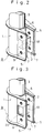
- Known knuckle brackets of this type are disclosed in Japanese Utility Model Publication No. 13790/86, U.S. Patent No. 4,491,339 and Japanese Patent Laid Open No. 160442/81, and the structure shown in Fig. 4 attached hereto is a typical prior art structure.
- The knuckle bracket illustrated in Fig. 4 and indicated at A comprises an
outer bracket 1 and aninner bracket 2. Theouter bracket 1 comprises aloop portion 4 which extends around anouter shell 3 and a pair ofclamp portions loop portion 4. Theinner bracket 2 comprises acurved backrest portion 6 which is in abutment with theouter shell 3 and a pair ofsupport pieces backrest portion 6. - A lower portion of the
outer shell 3 with ashock absorber 8 inserted therein is located within theloop portion 4 of theouter bracket 1, and thesupport pieces inner bracket 2 are clamped by theclamp portions outer bracket 1 while thebackrest portion 6 of theinner bracket 2 is kept in abutment with theouter shell 3. Theclamp portions 5 and thesupport pieces 7 are clamped together with bolts inserted intobolt holes 9. - However, when a shock input from the road surface is large, a bending load acting in a lateral direction X-X or a longitudinal direction Y-Y in Fig. 4 is imposed on the
outer shell 3 or the knuckle bracket A. In the case of a lateral load, theclamp portions support pieces outer shell 3. - DE-U-8517424 proposes modifying the above-described known knuckle bracket by incorporating an outwardly-bent extension to the top of the backrest portion. The support pieces are extended upwards to meet the sides of the backrest extension.
- According to the present invention, there is provided a knuckle bracket for mounting on a cylindrical item such as a shock absorber, said knuckle bracket comprising: an outer bracket having a loop portion, for receiving therein the cylindrical item, and a pair of clamp portions extending substantially in parallel from said loop portion; an inner bracket having a curved backrest portion and a pair of support pieces extending substantially in parallel from said backrest portion, said support pieces being inserted between and clampable to said clamp portions of said outer bracket and said backrest portion being abutable against the cylindrical item; and a reinforcing bracket which comprises a first wall which (i) extends at least across the gap between said support pieces and (ii) acts as a reinforcement to resist splaying apart of said support pieces; characterized in that said first wall is located between the ends of said inner bracket and is generally parallel to said backrest portion.
- The knuckle bracket of the present invention is capable of bearing lateral and longitudinal loads imposed on the shock absorber. This prevents opening and deformation of the clamp portions and support pieces and tilting of the knuckle bracket.
- Possible reinforcing brackets include: a bulge in a middle part of the backrest portion of the inner bracket; a cutout piece cut out of one of the clamp portions and extending through a cutout opening in one of the support pieces to the other one of the support pieces or the other one of the clamp portions; and a substantially U-shaped bracket located between the support pieces, with the free ends of the arms of the substantially U-shaped bracket pointing towards the backrest portion.
- When a longitudinal load is applied to the shock absorber, the front and rear outer peripheral portions of the shock absorber are supported by the loop portion of the outer bracket and the backrest portion of the inner bracket. When a lateral load is applied to the shock absorber, the loop portion of the outer bracket supports the outer peripheral side faces of the shock absorber. At this time, the support pieces of the inner bracket are prevented from being opened in the lateral direction by means of the first wall of the reinforcing bracket.
- The invention will now be described by way of non-limiting embodiments with reference to the accompany drawings, in which:-
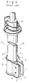
- Fig. 1 is a perspective view of a knuckle bracket according to an embodiment of the present invention;
- Fig. 2 is a perspective view of a knuckle bracket according to a further embodiment of the present invention;
- Fig. 3 is a perspective view of a knuckle bracket according to a still further embodiment of the present invention; and
- Fig. 4 is a perspective view of a conventional knuckle bracket.
- Figs. 1 to 3 illustrate embodiments of the present invention. The basic construction of the knuckle brackets B according to these three embodiments is the same as for the prior art knuckle bracket A illustrated in Fig. 4. Typically, each knuckle bracket B comprises an
outer bracket 1 and aninner bracket 2. Theouter bracket 1 comprises a loop portion serving as a socket for receiving a cylindrical member and a pair ofclamp portions inner bracket 2 comprises acurved backrest portion 6 and a pair ofsupport pieces backrest portion 6. - Into the loop portion of the
outer bracket 1 is inserted a lower portion of anouter shell 3 of a strut type shock absorber, and thebackrest 6 of theinner bracket 2 is in abutment with the front-facing outer periphery of theouter shell 3. - The
clamp portions outer bracket 1 and thesupport pieces inner bracket 2 interposed between the clamp portions are clamped together with bolts inserted intobolt holes 9. - Referring now to Fig. 1, a reinforcing
bracket 17 is provided integrally with the backrest portion of the inner bracket. - The reinforcing
bracket 17 is formed by bending an intermediate part of thebackrest portion 6 of theinner bracket 2 so as to form a bulge between thesupport pieces bracket 17 are welded to inner surfaces of thesupport pieces bracket 17, in cooperation with bolts, or alone, prevents thesupport pieces - Referring now to Fig. 2, a reinforcing
bracket 18 improved over that shown in Fig. 1 is used. More specifically, both end faces of the reinforcingbracket 18 which is bent centrally are welded to the opposed side faces of thesupport pieces - Referring now to Fig. 3, there is illustrated a knuckle bracket according to a still further embodiment of the present invention, in which a middle part of one
clamp portion 5 of anouter bracket 1 is cut out to form a cutout piece and this cutout piece is utilized as a reinforcingbracket 19. The reinforcingbracket 19 is bent laterally through an opening 20 of onesupport piece 7 and an end portion thereof is welded to an inner surface of theother support piece 7. Even when a lateral load is imposed on thesupport pieces - The following effects are attained by the present invention.
- ① Since a reinforcing bracket is mounted at least between a pair of support pieces of an inner bracket, even when a lateral load is imposed on the support pieces from, for example, a shock absorber passing through the bracket, the reinforcing bracket bears the load and prevents the support pieces from being opened, whereby deformation, tilting and disengagement of the knuckle bracket are prevented.
- (2) Since the basic form of an outer bracket and an inner bracket are the same as in the prior art and what is required is the mere addition thereto of a reinforcing bracket of simple structure, the invention is easy and cheap to implement.
- (3) In the prior art, resistance against deformation can be increased by increasing the wall thickness of the inner and outer brackets and the outer shell, but by using the reinforcing bracket of the present invention it is not necessary to increase the wall thickness of the inner and outer brackets and outer shell, and thus it is possible to attain a reduction in weight. Alternatively, with the present invention, the provision of a reinforcing bracket permits a decrease in wall thickness of the prior art outer shell and inner and outer brackets, whereby a reduction in weight can be attained.
Claims (5)
- A knuckle bracket (B) for mounting on a cylindrical item such as a shock absorber (3), said knuckle bracket (B) comprising:-
an outer bracket (1) having a loop portion, for receiving therein the cylindrical item (3), and a pair of clamp portions (5) extending substantially in parallel from said loop portion;
an inner bracket (2) having a curved backrest portion (6) and a pair of support pieces (7) extending substantially in parallel from said backrest portion (6), said support pieces (7) being inserted between and clampable to said clamp portions (5) of said outer bracket (1) and said backrest portion (6) being abutable against the cylindrical item (3); and
a reinforcing bracket (17, 18, 19) which comprises a first wall which (i) extends at least across the gap between said support pieces (7) and (ii) acts as a reinforcement to resist splaying apart of said support pieces (7);
characterized in that said first wall is located between the ends of said inner bracket (2) and is generally parallel to said backrest portion (6). - A knuckle bracket (B) according to claim 1, wherein said reinforcing bracket (17) comprises a bulge in a middle part of said backrest portion (6) of said inner bracket (2).
- A knuckle bracket (B) according to claim 1, wherein said reinforcing bracket (19) comprises a cutout piece cut out of one of said clamp portions (5) and extending through a cutout opening (20) in one of said support pieces (7) to the other one of said support pieces (7) or the other one of said clamp portions (5).
- A knuckle bracket (B) according to claim 1, wherein said reinforcing bracket (18) comprises a substantially U-shaped bracket (18) located between said support pieces (7), with the free ends of the arms of said substantially U-shaped bracket pointing towards said backrest portion (6).
- An assembly of a knuckle bracket (B) according to any one of claims 1 to 4 and a shock absorber (3), wherein said shock absorber (3) is located in said loop portion and said backrest portion (6) abuts against said shock absorber (3).
Applications Claiming Priority (5)
| Application Number | Priority Date | Filing Date | Title |
|---|---|---|---|
| JP8605590 | 1990-08-15 | ||
| JP86055/90 | 1990-08-15 | ||
| JP114202/90 | 1990-10-31 | ||
| JP1990114202U JP2529038Y2 (en) | 1990-08-15 | 1990-10-31 | Knuckle bracket |
| EP91307548A EP0476833B1 (en) | 1990-08-15 | 1991-08-15 | Knuckle bracket |
Related Parent Applications (1)
| Application Number | Title | Priority Date | Filing Date |
|---|---|---|---|
| EP91307548.7 Division | 1991-08-15 |
Publications (2)
| Publication Number | Publication Date |
|---|---|
| EP0621145A1 true EP0621145A1 (en) | 1994-10-26 |
| EP0621145B1 EP0621145B1 (en) | 1997-10-15 |
Family
ID=26427219
Family Applications (2)
| Application Number | Title | Priority Date | Filing Date |
|---|---|---|---|
| EP91307548A Expired - Lifetime EP0476833B1 (en) | 1990-08-15 | 1991-08-15 | Knuckle bracket |
| EP94201792A Expired - Lifetime EP0621145B1 (en) | 1990-08-15 | 1991-08-15 | Knuckle bracket |
Family Applications Before (1)
| Application Number | Title | Priority Date | Filing Date |
|---|---|---|---|
| EP91307548A Expired - Lifetime EP0476833B1 (en) | 1990-08-15 | 1991-08-15 | Knuckle bracket |
Country Status (4)
| Country | Link |
|---|---|
| US (2) | US5170973A (en) |
| EP (2) | EP0476833B1 (en) |
| JP (1) | JP2529038Y2 (en) |
| DE (2) | DE69109417T2 (en) |
Families Citing this family (33)
| Publication number | Priority date | Publication date | Assignee | Title |
|---|---|---|---|---|
| DE4321036A1 (en) * | 1993-06-24 | 1995-01-05 | Fichtel & Sachs Ag | Vibration damper with extension limit stop mounting |
| JP3520458B2 (en) * | 1994-12-14 | 2004-04-19 | カヤバ工業株式会社 | Knuckle bracket |
| US5893435A (en) * | 1995-12-20 | 1999-04-13 | Fichtel & Sachs Ag | Vibration damper for a motor vehicle, the vibration damper having a decompression stop boundary bracket |
| DE19647411C1 (en) * | 1996-11-15 | 1998-03-05 | Mannesmann Sachs Ag | Fixing bracket for vibration damper |
| WO1999004104A1 (en) * | 1997-07-15 | 1999-01-28 | Komatsu Ltd. | Structure for working unit for bucket excavators and method for manufacturing the same |
| US6367751B1 (en) * | 2000-08-14 | 2002-04-09 | General Motors Corporation | Bracket assembly |
| DE10115373C1 (en) * | 2001-03-28 | 2002-10-17 | Zf Sachs Ag | Articulated support for a piston-cylinder unit |
| DE10122794B4 (en) * | 2001-05-11 | 2006-08-24 | Zf Sachs Ag | Bracket for fastening a piston-cylinder unit |
| DE102004036090A1 (en) * | 2004-07-24 | 2006-02-16 | Zf Friedrichshafen Ag | Cylinder assembly with one axle connection |
| DE102005007382B3 (en) * | 2005-02-18 | 2006-04-06 | Zf Friedrichshafen Ag | Vibration damper for machine has deformation region permitting displacement of component of tubular body above normal load |
| DE102006008732A1 (en) * | 2006-02-24 | 2007-09-20 | Schaeffler Kg | Receiving device for a strut |
| JP4768492B2 (en) * | 2006-03-30 | 2011-09-07 | カヤバ工業株式会社 | Knuckle bracket |
| JP4908059B2 (en) * | 2006-05-22 | 2012-04-04 | カヤバ工業株式会社 | Strut type shock absorber |
| JP4663582B2 (en) * | 2006-05-30 | 2011-04-06 | カヤバ工業株式会社 | Strut type shock absorber |
| DE102006036506B3 (en) * | 2006-08-04 | 2008-02-07 | Zf Friedrichshafen Ag | Vibration damper with a bracket |
| US20080066289A1 (en) * | 2006-09-12 | 2008-03-20 | Kayaba Industry Co., Ltd. | Through-hole stamping method in bracket made of bent plate |
| US7793954B2 (en) * | 2007-06-22 | 2010-09-14 | Radar Industries, Inc. | Suspension system for a vehicle |
| ES2350082B1 (en) * | 2009-05-07 | 2011-11-18 | Kyb Suspensions Europe, S.A. | IMPROVED UNION BETWEEN AMARRE AND TUBE OF A VEHICLE SUSPENSION AND UNION SUCH FIXING PROCESS |
| US20110100148A1 (en) * | 2009-10-29 | 2011-05-05 | Mando Corporation | Crash energy absorbing mounting bracket and steering column of vehicle having the same |
| JP2011143837A (en) * | 2010-01-15 | 2011-07-28 | Honda Motor Co Ltd | Off-road traveling vehicle |
| US8705686B2 (en) | 2010-12-28 | 2014-04-22 | Ge-Hitachi Nuclear Energy Americas Llc | Adjustable hard stops for nuclear reactor restrainer brackets and methods of using the same |
| FR2973737A1 (en) * | 2011-04-11 | 2012-10-12 | Peugeot Citroen Automobiles Sa | Support for connection between lower end of shock absorber and axle of car, has half-reinforcement provided with two uprights that are arranged in parallel manner against inner walls of another two uprights of envelope |
| US10024338B2 (en) * | 2011-05-12 | 2018-07-17 | Ge-Hitachi Nuclear Energy Americas Llc | Method and apparatus for a BWR jet pump inlet mixer compliant stop |
| FR2975315B1 (en) * | 2011-05-16 | 2013-07-05 | Peugeot Citroen Automobiles Sa | SUPPORT FOR CYLINDRICAL PIECE |
| JP6082295B2 (en) * | 2013-03-26 | 2017-02-15 | Kyb株式会社 | Knuckle bracket, pair of knuckle bracket, and suspension manufacturing method |
| JP6043230B2 (en) * | 2013-04-10 | 2016-12-14 | Kyb株式会社 | Manufacturing apparatus and manufacturing method for knuckle bracket |
| DE102014204090B4 (en) * | 2014-03-06 | 2018-12-27 | Zf Friedrichshafen Ag | Strut assembly |
| DE102014211632A1 (en) * | 2014-06-17 | 2015-12-17 | Bayerische Motoren Werke Aktiengesellschaft | Wheel carrier of a vehicle with a clamp-seat connection |
| US9869331B2 (en) * | 2015-08-11 | 2018-01-16 | Emadeddin Zahri Muntasser | Universal marking bracket |
| US10368707B2 (en) | 2016-03-03 | 2019-08-06 | Emerson Electric Co. | Adjustable vacuum tube clamp assembly and vacuum cleaners including same |
| USD803493S1 (en) | 2016-06-17 | 2017-11-21 | Emerson Electric Co. | Clamp for vacuum tube assemblies |
| US11084348B2 (en) | 2018-02-28 | 2021-08-10 | J & J Holdings and Investments, LLC | Clamp, mount tab and tether for limit strap |
| CN113602351A (en) * | 2021-08-18 | 2021-11-05 | 东风柳州汽车有限公司 | Knuckle assembly limit structure and damper assembly |
Citations (8)
| Publication number | Priority date | Publication date | Assignee | Title |
|---|---|---|---|---|
| US3941401A (en) * | 1974-12-23 | 1976-03-02 | Ford Motor Company | Independent wheel suspension having suspension strut |
| JPS56160442A (en) * | 1980-05-14 | 1981-12-10 | Tokico Ltd | Manufacture of bracket for cylindrical vessel |
| JPS5863506A (en) * | 1981-10-09 | 1983-04-15 | Nissan Motor Co Ltd | Fitting structure of strut |
| DE8517424U1 (en) * | 1985-06-14 | 1985-10-10 | Adam Opel AG, 6090 Rüsselsheim | Mounting bracket |
| US4618162A (en) * | 1985-08-29 | 1986-10-21 | Shim-A-Line, Inc. | Device and method for adjusting camber in a strut-type vehicle suspension |
| US4753462A (en) * | 1987-07-28 | 1988-06-28 | Liu Chin Lang | Adjustable tube clamping connector |
| DE3932329A1 (en) * | 1988-10-11 | 1990-04-12 | Opel Adam Ag | Front suspension system for motor vehicle - has steering arm attached to wheel spindle bracket which is bolted to spring strut |
| US4948160A (en) * | 1989-01-17 | 1990-08-14 | Barry David L | Method and apparatus for modifying wheel alignment in strut type suspension |
Family Cites Families (6)
| Publication number | Priority date | Publication date | Assignee | Title |
|---|---|---|---|---|
| JPS589766Y2 (en) * | 1977-04-18 | 1983-02-22 | トヨタ自動車株式会社 | Vehicle wheel camber adjustment device |
| DE2932138A1 (en) * | 1979-08-08 | 1981-02-26 | Fichtel & Sachs Ag | BRACKET FOR VEHICLE SHOCK ABSORBER |
| DE3105170A1 (en) * | 1981-02-13 | 1982-09-02 | Fichtel & Sachs Ag, 8720 Schweinfurt | VIBRATION DAMPER OR SHOCK ABSORBER WITH AT LEAST ONE FITTING ARRANGED ON THE CONTAINER TUBE |
| US4491339A (en) * | 1981-12-30 | 1985-01-01 | Kayaba Kkk | Strut for McPherson type automobile suspensions |
| EP0083669B1 (en) * | 1981-12-31 | 1986-03-12 | Kayaba Kogyo Kabushiki Kaisha | Strut for mcpherson type automobile suspensions |
| FR2558230A1 (en) * | 1984-01-17 | 1985-07-19 | Fichtel & Sachs Ag | Combined element forming a spring and a shock absorber. |
-
1990
- 1990-10-31 JP JP1990114202U patent/JP2529038Y2/en not_active Expired - Fee Related
-
1991
- 1991-08-07 US US07/741,144 patent/US5170973A/en not_active Expired - Lifetime
- 1991-08-15 EP EP91307548A patent/EP0476833B1/en not_active Expired - Lifetime
- 1991-08-15 DE DE69109417T patent/DE69109417T2/en not_active Expired - Fee Related
- 1991-08-15 DE DE69127983T patent/DE69127983T2/en not_active Expired - Fee Related
- 1991-08-15 EP EP94201792A patent/EP0621145B1/en not_active Expired - Lifetime
-
1992
- 1992-10-27 US US07/966,944 patent/US5308032A/en not_active Expired - Fee Related
Patent Citations (8)
| Publication number | Priority date | Publication date | Assignee | Title |
|---|---|---|---|---|
| US3941401A (en) * | 1974-12-23 | 1976-03-02 | Ford Motor Company | Independent wheel suspension having suspension strut |
| JPS56160442A (en) * | 1980-05-14 | 1981-12-10 | Tokico Ltd | Manufacture of bracket for cylindrical vessel |
| JPS5863506A (en) * | 1981-10-09 | 1983-04-15 | Nissan Motor Co Ltd | Fitting structure of strut |
| DE8517424U1 (en) * | 1985-06-14 | 1985-10-10 | Adam Opel AG, 6090 Rüsselsheim | Mounting bracket |
| US4618162A (en) * | 1985-08-29 | 1986-10-21 | Shim-A-Line, Inc. | Device and method for adjusting camber in a strut-type vehicle suspension |
| US4753462A (en) * | 1987-07-28 | 1988-06-28 | Liu Chin Lang | Adjustable tube clamping connector |
| DE3932329A1 (en) * | 1988-10-11 | 1990-04-12 | Opel Adam Ag | Front suspension system for motor vehicle - has steering arm attached to wheel spindle bracket which is bolted to spring strut |
| US4948160A (en) * | 1989-01-17 | 1990-08-14 | Barry David L | Method and apparatus for modifying wheel alignment in strut type suspension |
Non-Patent Citations (2)
| Title |
|---|
| PATENT ABSTRACTS OF JAPAN vol. 6, no. 45 (M - 118)<923> 20 March 1982 (1982-03-20) * |
| PATENT ABSTRACTS OF JAPAN vol. 7, no. 157 (M - 227)<1302> 9 July 1983 (1983-07-09) * |
Also Published As
| Publication number | Publication date |
|---|---|
| DE69109417D1 (en) | 1995-06-08 |
| DE69127983D1 (en) | 1997-11-20 |
| DE69109417T2 (en) | 1996-01-04 |
| EP0621145B1 (en) | 1997-10-15 |
| DE69127983T2 (en) | 1998-02-12 |
| US5170973A (en) | 1992-12-15 |
| EP0476833A1 (en) | 1992-03-25 |
| US5308032A (en) | 1994-05-03 |
| JP2529038Y2 (en) | 1997-03-12 |
| JPH0471836U (en) | 1992-06-25 |
| EP0476833B1 (en) | 1995-05-03 |
Similar Documents
| Publication | Publication Date | Title |
|---|---|---|
| EP0621145B1 (en) | Knuckle bracket | |
| US5845938A (en) | Deformable suspension and for automotive vehicle | |
| US5611569A (en) | Vehicle subframe assembly | |
| JP3191654B2 (en) | Suspension arm | |
| US4348042A (en) | Vehicle bumper assembly | |
| EP1037756B1 (en) | Tapered convolute leaf spring for truck suspensions | |
| US5730547A (en) | Knuckle bracket | |
| US4501436A (en) | Supporting assembly for a suspension | |
| JPH11254935A (en) | Vehicle stabilizer | |
| US6305701B1 (en) | One piece mounting bracket for automotive suspension dampers, including attachment for stabilizer bar | |
| JPH08216Y2 (en) | Energy absorption type steering column | |
| EP0413158B1 (en) | Vehicle rear suspension mounting structure | |
| US5641180A (en) | Vehicle subframe assembly | |
| US5310210A (en) | Upper control arm for vehicle suspension system | |
| US4575153A (en) | Back frame in a seat back for a vehicle seat | |
| EP0083669B1 (en) | Strut for mcpherson type automobile suspensions | |
| JP3389767B2 (en) | Shock absorbing steering column device | |
| JP4146552B2 (en) | Vehicle stabilizer mounting structure | |
| JPH11115865A (en) | Elastic and operable axle suspending device for two-wheeler | |
| EP1133412B1 (en) | A motor vehicle bumper mounting assembly | |
| JP3128678B2 (en) | Mounting structure of shock absorber | |
| US9180918B2 (en) | Cab tilting device | |
| JPH11170879A (en) | Transmission mount structure for automobile | |
| CN115210131B (en) | Cab mounting structure | |
| JP4000776B2 (en) | Rear suspension structure |
Legal Events
| Date | Code | Title | Description |
|---|---|---|---|
| PUAI | Public reference made under article 153(3) epc to a published international application that has entered the european phase |
Free format text: ORIGINAL CODE: 0009012 |
|
| AC | Divisional application: reference to earlier application |
Ref document number: 476833 Country of ref document: EP |
|
| AK | Designated contracting states |
Kind code of ref document: A1 Designated state(s): BE DE GB NL |
|
| 17P | Request for examination filed |
Effective date: 19950329 |
|
| 17Q | First examination report despatched |
Effective date: 19960806 |
|
| GRAG | Despatch of communication of intention to grant |
Free format text: ORIGINAL CODE: EPIDOS AGRA |
|
| GRAH | Despatch of communication of intention to grant a patent |
Free format text: ORIGINAL CODE: EPIDOS IGRA |
|
| GRAH | Despatch of communication of intention to grant a patent |
Free format text: ORIGINAL CODE: EPIDOS IGRA |
|
| GRAA | (expected) grant |
Free format text: ORIGINAL CODE: 0009210 |
|
| AC | Divisional application: reference to earlier application |
Ref document number: 476833 Country of ref document: EP |
|
| AK | Designated contracting states |
Kind code of ref document: B1 Designated state(s): BE DE GB NL |
|
| REF | Corresponds to: |
Ref document number: 69127983 Country of ref document: DE Date of ref document: 19971120 |
|
| PLBE | No opposition filed within time limit |
Free format text: ORIGINAL CODE: 0009261 |
|
| STAA | Information on the status of an ep patent application or granted ep patent |
Free format text: STATUS: NO OPPOSITION FILED WITHIN TIME LIMIT |
|
| 26N | No opposition filed | ||
| REG | Reference to a national code |
Ref country code: GB Ref legal event code: IF02 |
|
| PGFP | Annual fee paid to national office [announced via postgrant information from national office to epo] |
Ref country code: NL Payment date: 20040803 Year of fee payment: 14 |
|
| PGFP | Annual fee paid to national office [announced via postgrant information from national office to epo] |
Ref country code: GB Payment date: 20040811 Year of fee payment: 14 |
|
| PGFP | Annual fee paid to national office [announced via postgrant information from national office to epo] |
Ref country code: DE Payment date: 20040826 Year of fee payment: 14 |
|
| PGFP | Annual fee paid to national office [announced via postgrant information from national office to epo] |
Ref country code: BE Payment date: 20041020 Year of fee payment: 14 |
|
| PG25 | Lapsed in a contracting state [announced via postgrant information from national office to epo] |
Ref country code: GB Free format text: LAPSE BECAUSE OF NON-PAYMENT OF DUE FEES Effective date: 20050815 |
|
| PG25 | Lapsed in a contracting state [announced via postgrant information from national office to epo] |
Ref country code: BE Free format text: LAPSE BECAUSE OF NON-PAYMENT OF DUE FEES Effective date: 20050831 |
|
| PG25 | Lapsed in a contracting state [announced via postgrant information from national office to epo] |
Ref country code: NL Free format text: LAPSE BECAUSE OF NON-PAYMENT OF DUE FEES Effective date: 20060301 Ref country code: DE Free format text: LAPSE BECAUSE OF NON-PAYMENT OF DUE FEES Effective date: 20060301 |
|
| GBPC | Gb: european patent ceased through non-payment of renewal fee |
Effective date: 20050815 |
|
| NLV4 | Nl: lapsed or anulled due to non-payment of the annual fee |
Effective date: 20060301 |
|
| BERE | Be: lapsed |
Owner name: *KAYABA KOGYO K.K. Effective date: 20050831 |