EP0623710A1 - Non-contact sanitary valve - Google Patents
Non-contact sanitary valve Download PDFInfo
- Publication number
- EP0623710A1 EP0623710A1 EP93107413A EP93107413A EP0623710A1 EP 0623710 A1 EP0623710 A1 EP 0623710A1 EP 93107413 A EP93107413 A EP 93107413A EP 93107413 A EP93107413 A EP 93107413A EP 0623710 A1 EP0623710 A1 EP 0623710A1
- Authority
- EP
- European Patent Office
- Prior art keywords
- sensors
- sanitary fitting
- water
- transmitters
- water jet
- Prior art date
- Legal status (The legal status is an assumption and is not a legal conclusion. Google has not performed a legal analysis and makes no representation as to the accuracy of the status listed.)
- Granted
Links
Images
Classifications
-
- E—FIXED CONSTRUCTIONS
- E03—WATER SUPPLY; SEWERAGE
- E03C—DOMESTIC PLUMBING INSTALLATIONS FOR FRESH WATER OR WASTE WATER; SINKS
- E03C1/00—Domestic plumbing installations for fresh water or waste water; Sinks
- E03C1/02—Plumbing installations for fresh water
- E03C1/05—Arrangements of devices on wash-basins, baths, sinks, or the like for remote control of taps
- E03C1/055—Electrical control devices, e.g. with push buttons, control panels or the like
- E03C1/057—Electrical control devices, e.g. with push buttons, control panels or the like touchless, i.e. using sensors
Abstract
Description
Die Erfindung betrifft eine berührungslos betätigbare Sanitärarmatur mit einem an eine Wasserleitung angeschlossenen Wasserauslauf und einem diesem vorgeschalteten Absperrventil, das mittels einer Steuerschaltung in Abhängigkeit von den Signalen einer annäherungsempfindlichen Sensoreinrichtung betätigbar ist.The invention relates to a contactlessly operated sanitary fitting with a water outlet connected to a water pipe and a shut-off valve connected upstream thereof, which can be operated by means of a control circuit as a function of the signals of an proximity-sensitive sensor device.
Sanitärarmaturen dieser Art sind bekannt. Beispielsweise zeigt EP-A2-0 400 688 einen Wasserhahn, der ein am Ende nach unten gebogenes horizontales Auslaufrohr aufweist. Ein Ultraschallsensor, bestehend aus einem Sender und einem Empfänger, ist knapp hinter dem Auslaufbogen angeordnet. Der Sender strahlt im wesentlichen nach unten in dasselbe Zielgebiet wie der Wasserstrahl.Sanitary fittings of this type are known. For example, EP-A2-0 400 688 shows a faucet which has a horizontal outlet pipe bent downward at the end. An ultrasonic sensor, consisting of a transmitter and a receiver, is located just behind the outlet bend. The transmitter radiates essentially downwards into the same target area as the water jet.
Eine solche Anordnung eines einzigen Sensors ist in mehrfacher Hinsicht unzulänglich. Füllt man ein Gefäß mit Wasser, so kann der Wasserstrahl nur dadurch abgestellt werden, daß man das Gefäß zur Seite nimmt, wobei es unvermeidlich ist, daß das Gefäß auch außen benetzt wird. Insbesondere bei einem kleinen Gefäß kann es sein, daß es vom Sendestrahl nicht erfaßt wird, so daß das Ventil nur bei besonderer Manipulation öffnet. Eine meist vorhandene kleine Schaltverzögerung macht sich insofern störend bemerkbar, als das Wasser erst zu laufen beginnt, wenn die Hände unter der Auslauföffnung in Position gebracht sind. Schwierigkeiten können sich auch ergeben bei einer unerwünschten Interaktion des Sendestrahls mit dem Wasserstrahl. Wenn nämlich der Wasserstrahl eine Reflexion der Sendestrahlen bewirkt, bleibt das Wasser auch nach dem Zurücknehmen der Hände eingeschaltet. Schließlich ergeben sich häufig unerwünschte Reflexionen am Becken, die zwar durch genaue Einstellung des Schaltabstandes beherrscht werden können, jedoch eine Abstimmung auf das im Einzelfall verwendete Waschbecken notwendig machen.Such an arrangement of a single sensor is inadequate in several respects. If you fill a vessel with water, the water jet can only be switched off that the vessel is taken aside, and it is inevitable that the vessel will also be wetted on the outside. In particular in the case of a small vessel, it may be that it is not caught by the transmission beam, so that the valve only opens when particularly manipulated. A small switching delay, which is usually present, is noticeable insofar as the water only starts to run when the hands are positioned under the outlet opening. Difficulties can also arise with an undesired interaction of the transmission beam with the water jet. If the water jet causes the transmission beams to be reflected, the water remains switched on even after the hands have been removed. Finally, there are often undesirable reflections on the basin, which can be controlled by precise adjustment of the switching distance, but make it necessary to match the wash basin used in the individual case.
Der Erfindung liegt die Aufgabe zugrunde, das Füllen eines Gefäßes zu erleichtern, die Synchronisation des Beginns des Wasserlaufes und der Zuführbewegung des Reflexionsobjektes, z. B. der Hände, zu verbessern und unerwünschte Reflexionen des Sendestrahls am Wasserstrahl und am Becken zu vermeiden.The invention has for its object to facilitate the filling of a vessel, the synchronization of the beginning of the watercourse and the feed movement of the reflection object, for. B. the hands to improve and avoid unwanted reflections of the transmission beam on the water jet and the pool.
Diese Aufgabe wird ausgehend von einer Sanitärarmatur der einleitend bezeichneten Art erfindungsgemäß durch die Merkmale des Patentanspruchs 1 gelöst. Danach sind mehrere Sensoren vorgesehen, von denen mindestens einer an jeder Seite der Symmetrieebene der Armatur angeordnet ist. Vorzugsweise divergieren die Wirkungsbereiche der Sensoren, d. h. die Strahlungskegel oder -keulen. Damit ist es möglich, sie am Wasserstrahl vorbeizulenken, so daß dieser nicht getroffen wird. Zweckmäßigerweise wirken die Sensoren unabhängig voneinander, d. h., daß es genügt, einen Reflexionsgegenstand in den Wirkungsbereich eines der beiden Sensoren einzuführen, um das Wasser fließen zu lassen.This object is achieved on the basis of a sanitary fitting of the type described in the introduction by the features of patent claim 1. Thereafter, several sensors are provided, at least one of which is arranged on each side of the plane of symmetry of the fitting. The effective ranges of the sensors, ie the radiation cones or lobes, preferably diverge. This makes it possible to direct them past the water jet so that it is not hit. The sensors expediently act independently of one another, ie it is sufficient to introduce a reflection object into the effective range of one of the two sensors in order to allow the water to flow.
Dadurch ist es möglich, schon bei Annäherung beispielsweise der Hände an den Wasserstrahlbereich das Wasser fließen zu lassen, so daß dem Benutzer die Schaltverzögerung nicht zum Bewußtsein kommt. Infolge der doppelseitigen Anordnung der Sensoren gilt das für Rechts- und Linkshänder. Man kann auch von vorne kommend ein Gefäß unter den Auslauf halten und durch eine Annäherungsbewegung mit der anderen Hand das Wasser zum Laufen bringen und wieder abstellen. Man kann also das Gefäß exakt füllen, ohne es unter den laufenden Strahl wegziehen zu müssen. Auch dies ist im Rechts- und Linkshandbetrieb möglich.This makes it possible to let the water flow already when the hands, for example, approach the water jet area, so that the user does not become aware of the switching delay. Due to the double-sided arrangement of the sensors, this applies to right-handed and left-handed users. You can also hold a container under the spout coming from the front and bring the water up and down again by moving your hand closer. So you can fill the vessel exactly without having to pull it under the current jet. This is also possible in right- and left-hand operation.
Die von der Mittelebene weggerichteten Sendestrahlen treffen erst in einem verhältnismäßig großen Abstand auf das Becken, so daß es leichter ist, einen für die Handhabung geeigneten Schaltabstand zu wählen, der Beckenreflexionen ausschließt. Außerdem ist es in dieser Hinsicht zweckmäßig, die Sendekegel bzw. -keulen der Sensoren in die Horizontale zu legen oder nur wenig gegenüber der Horizontalen nach unten zu neigen und sie auf diese Weise über den Beckenrand hinweg zu führen.The transmission beams directed away from the center plane only hit the basin at a relatively large distance, so that it is easier to choose a switching distance that is suitable for handling and excludes basin reflections. In this regard, it is also expedient to place the transmission cones or lobes of the sensors in the horizontal or to incline them only slightly relative to the horizontal and in this way to guide them over the edge of the pool.
Zwei unabhängige Sensoren lassen sich vorzugsweise dadurch verwirklichen, daß zwei Sender und ein gemeinsamer, zwischen den Sendern angeordneter Empfänger vorgesehen sind. Es kann aber auch jedem Sender sein eigener Empfänger zugeordnet werden. Alle diese Überlegungen gelten vorzugsweise für mit Infrarotstrahlen arbeitende Sensoren. Eine Anwendung auf Ultraschall- oder Mikrowellensensoren oder Sensoren anderer Strahlungsarten ist jedoch nicht ausgeschlossen.Two independent sensors can preferably be realized in that two transmitters and a common receiver arranged between the transmitters are provided. However, each transmitter can also be assigned its own receiver. All of these considerations preferably apply to sensors working with infrared rays. However, application to ultrasonic or microwave sensors or sensors of other types of radiation is not excluded.
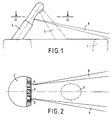
Ein Ausführungsbeispiel der Erfindung wird nachfolgend anhand der Zeichnung erläutert. Im einzelnen zeigt
- Fig. 1
- eine Seitenansicht einer Wasserauslaufarmatur mit angedeutetem Beckenrand und
- Fig. 2
- einen Horizontalschnitt II-II der Anordnung nach Fig. 1 in größerem Maßstab.
- Fig. 1
- a side view of a water outlet fitting with indicated pool edge and
- Fig. 2
- a horizontal section II-II of the arrangement of FIG. 1 on a larger scale.
Das Waschbecken gemäß Fig. 1 hat einen vorderen, dem Benutzer zugewandten Rand 1. Eine schräg nach vorn hochstehende gestreckte Auslaufarmatur 2 ist am hinteren Beckenrand befestigt. Sie endet oben in einem gewölbten Kopf mit einer Auslauföffnung, deren Wasserstrahl 3 schräg nach unten in das Becken gerichtet ist. Der obere Abschnitt der Auslaufarmatur 2 hat einen nach vorn abgeflachten Querschnitt, wie Fig. 2 zeigt. In dieser abgeflachten Zone wenig unterhalb der Auslauföffnung sind auf gleicher Höhe zwei Infrarotsender 4 und 5 angeordnet, die einen gemeinsamen Infrarotempfänger 6 zwischen sich aufnehmen. Die beiden Sender 4 und 5 befinden sich somit zu beiden Seiten der vertikalen Symmetrieebene 7 der Armatur 2, in welcher der Infrarotempfänger 6 liegt und die den Wasserstrahl 3 mittig durchschneidet. Die durch je zwei Grenzstrahlen angedeuteten Sendestrahlenkegel 8 und 9 verlaufen mit nur geringer Neigung über den vorderen Beckenrand 1 hinweg und in der Draufsicht nach Fig. 2 laufen die Sendestrahlenkegel von der Symmetrieebene 7 weg auseinander. Sie treffen den in Fig. 2 im Querschnitt angedeuteten Wasserstrahl 3 nicht.The wash basin according to FIG. 1 has a front edge 1 which faces the user. It ends at the top in a curved head with an outlet opening, the
Bei einer solchen Anordnung hat es sich als sinnvoll erwiesen, den Schaltabstand auf etwa 15 cm von dem Sensor weg einzustellen. Bewegt man dabei die Hände in das Gebiet des zu erwartenden Wasserstrahls, so wird schon beim Heranbewegen das Schaltsignal ausgelöst, so daß der Wasserstrahl angenehm schnell einsetzt. Ein mit einer Hand gehaltenes, von unten herangeführtes Gefäß kann durch Manipulation der anderen Hand leicht gefüllt werden. Reflexionen am Becken sind ausgeschlossen.With such an arrangement, it has proven to be expedient to set the switching distance to approximately 15 cm away from the sensor. If you move your hands in the area of the water jet to be expected, the switching signal is triggered as soon as you move up so that the water jet starts pleasantly quickly. A vessel held from below with one hand can easily be filled by manipulating the other hand. Reflections on the pool are excluded.
Claims (5)
Priority Applications (2)
| Application Number | Priority Date | Filing Date | Title |
|---|---|---|---|
| EP19930107413 EP0623710B1 (en) | 1993-05-07 | 1993-05-07 | Non-contact sanitary valve |
| DE59308847T DE59308847D1 (en) | 1993-05-07 | 1993-05-07 | Non-contact sanitary fitting |
Applications Claiming Priority (1)
| Application Number | Priority Date | Filing Date | Title |
|---|---|---|---|
| EP19930107413 EP0623710B1 (en) | 1993-05-07 | 1993-05-07 | Non-contact sanitary valve |
Publications (2)
| Publication Number | Publication Date |
|---|---|
| EP0623710A1 true EP0623710A1 (en) | 1994-11-09 |
| EP0623710B1 EP0623710B1 (en) | 1998-08-05 |
Family
ID=8212883
Family Applications (1)
| Application Number | Title | Priority Date | Filing Date |
|---|---|---|---|
| EP19930107413 Expired - Lifetime EP0623710B1 (en) | 1993-05-07 | 1993-05-07 | Non-contact sanitary valve |
Country Status (2)
| Country | Link |
|---|---|
| EP (1) | EP0623710B1 (en) |
| DE (1) | DE59308847D1 (en) |
Cited By (5)
| Publication number | Priority date | Publication date | Assignee | Title |
|---|---|---|---|---|
| AT404150B (en) * | 1996-04-15 | 1998-08-25 | Wimberger Herbert | CONTROL DEVICE FOR AN EXHAUST VALVE AND METHOD FOR CONTROLLING AN EXHAUST VALVE |
| GB2457141A (en) * | 2008-02-01 | 2009-08-12 | Kibuts Glil Yam | Automatic faucet |
| US7614096B2 (en) * | 2005-03-16 | 2009-11-10 | Masco Corporation Of Indiana | Control for an automatic plumbing device |
| EP2236880A1 (en) * | 2008-01-29 | 2010-10-06 | Shanghai Kohler Electronics, Ltd. | Infrared induction device |
| EP2513383A1 (en) * | 2009-12-16 | 2012-10-24 | Kohler Co. | Touchless faucet assembly |
Citations (6)
| Publication number | Priority date | Publication date | Assignee | Title |
|---|---|---|---|---|
| DE1658243A1 (en) * | 1966-03-11 | 1970-09-17 | Instr N Inor Ab Fa | Device for wash basins with photoelectrically controlled water valve |
| DE1609216B2 (en) * | 1965-08-31 | 1973-04-05 | Tateisi Electronics Co , Kyoto (Japan) | DEVICE FOR THE AUTOMATIC CONTROL OF A WATER OUTLET |
| DE3537678A1 (en) * | 1985-10-23 | 1987-04-23 | Peter Wilfred Auge | Shutoff fixture for fluids which can be actuated in a contactless fashion |
| US4767922A (en) * | 1986-08-25 | 1988-08-30 | Honeywell Inc. | Hand presence activated water faucet controller |
| EP0400688A2 (en) * | 1983-09-23 | 1990-12-05 | RECURRENT SOLUTIONS, Inc. | Ultrasonic flow-control system |
| EP0448421A1 (en) * | 1990-03-23 | 1991-09-25 | Les Robinets Presto Société Anonyme | Valve operating means with optical detection |
-
1993
- 1993-05-07 DE DE59308847T patent/DE59308847D1/en not_active Expired - Fee Related
- 1993-05-07 EP EP19930107413 patent/EP0623710B1/en not_active Expired - Lifetime
Patent Citations (6)
| Publication number | Priority date | Publication date | Assignee | Title |
|---|---|---|---|---|
| DE1609216B2 (en) * | 1965-08-31 | 1973-04-05 | Tateisi Electronics Co , Kyoto (Japan) | DEVICE FOR THE AUTOMATIC CONTROL OF A WATER OUTLET |
| DE1658243A1 (en) * | 1966-03-11 | 1970-09-17 | Instr N Inor Ab Fa | Device for wash basins with photoelectrically controlled water valve |
| EP0400688A2 (en) * | 1983-09-23 | 1990-12-05 | RECURRENT SOLUTIONS, Inc. | Ultrasonic flow-control system |
| DE3537678A1 (en) * | 1985-10-23 | 1987-04-23 | Peter Wilfred Auge | Shutoff fixture for fluids which can be actuated in a contactless fashion |
| US4767922A (en) * | 1986-08-25 | 1988-08-30 | Honeywell Inc. | Hand presence activated water faucet controller |
| EP0448421A1 (en) * | 1990-03-23 | 1991-09-25 | Les Robinets Presto Société Anonyme | Valve operating means with optical detection |
Cited By (9)
| Publication number | Priority date | Publication date | Assignee | Title |
|---|---|---|---|---|
| AT404150B (en) * | 1996-04-15 | 1998-08-25 | Wimberger Herbert | CONTROL DEVICE FOR AN EXHAUST VALVE AND METHOD FOR CONTROLLING AN EXHAUST VALVE |
| US7614096B2 (en) * | 2005-03-16 | 2009-11-10 | Masco Corporation Of Indiana | Control for an automatic plumbing device |
| EP2236880A1 (en) * | 2008-01-29 | 2010-10-06 | Shanghai Kohler Electronics, Ltd. | Infrared induction device |
| US20100308224A1 (en) * | 2008-01-29 | 2010-12-09 | Weigen Chen | Infrared sensing device |
| EP2236880A4 (en) * | 2008-01-29 | 2011-01-12 | Shanghai Kohler Electronics | Infrared induction device |
| US8421020B2 (en) * | 2008-01-29 | 2013-04-16 | Shanghai Kohler Electronics, Ltd. | Infrared sensing device |
| GB2457141A (en) * | 2008-02-01 | 2009-08-12 | Kibuts Glil Yam | Automatic faucet |
| EP2513383A1 (en) * | 2009-12-16 | 2012-10-24 | Kohler Co. | Touchless faucet assembly |
| US11859375B2 (en) | 2009-12-16 | 2024-01-02 | Kohler Co. | Touchless faucet assembly and method of operation |
Also Published As
| Publication number | Publication date |
|---|---|
| DE59308847D1 (en) | 1998-09-10 |
| EP0623710B1 (en) | 1998-08-05 |
Similar Documents
| Publication | Publication Date | Title |
|---|---|---|
| DE7024995U (en) | Dishwasher | |
| EP2342388A1 (en) | Sink and arrangement of a sanitary fitting on a sink | |
| EP0623710A1 (en) | Non-contact sanitary valve | |
| EP0240706B1 (en) | Venturi-mixing device for making and dispensing mixed beverages, with rinsing means | |
| AT395675B (en) | COFFEE MACHINE | |
| DE102004062243A1 (en) | Dishwasher with deflector | |
| DE3529517C2 (en) | plow | |
| DE3213488A1 (en) | Device for cleaning portioners for ice cream | |
| DE2309718C3 (en) | Flushing unit | |
| DE2548002A1 (en) | BEVERAGE DISPENSER WITH DOUBLE OPERATION | |
| EP2275608A1 (en) | Faucet with at least one control for temperature and/or water flow | |
| DE2852629A1 (en) | STATIONAL WATER OUTLET VALVE | |
| DE2107988C3 (en) | Sewer cleaning device | |
| DE3338483C2 (en) | ||
| DE19618645A1 (en) | Flushing device for toilet | |
| AT1579U1 (en) | RINSING DEVICE FOR SPOON-LIKE ITEMS, IN PARTICULAR FOR ICE PORTIONERS | |
| CH664295A5 (en) | Flush valve on ONE ROUND POOLS FOR THE CLEANING. | |
| DE102015111811B4 (en) | Washing system for a dishwasher, and dishwasher with such a washing system | |
| DE956763C (en) | Flush toilet for railroad cars or the like. | |
| DE2819984C2 (en) | Device for spraying disinfectants | |
| EP0583785A1 (en) | Watertap with proximity sensor | |
| DE102022125164A1 (en) | Watering cans with controlled shower head | |
| DE2153110B2 (en) | WASHBASIN FITTING | |
| EP1223250B1 (en) | Urinal | |
| DE2442480B2 (en) | Calibration device for plastic extrudate |
Legal Events
| Date | Code | Title | Description |
|---|---|---|---|
| PUAI | Public reference made under article 153(3) epc to a published international application that has entered the european phase |
Free format text: ORIGINAL CODE: 0009012 |
|
| AK | Designated contracting states |
Kind code of ref document: A1 Designated state(s): DE IT |
|
| 17P | Request for examination filed |
Effective date: 19950406 |
|
| 17Q | First examination report despatched |
Effective date: 19961210 |
|
| GRAG | Despatch of communication of intention to grant |
Free format text: ORIGINAL CODE: EPIDOS AGRA |
|
| GRAG | Despatch of communication of intention to grant |
Free format text: ORIGINAL CODE: EPIDOS AGRA |
|
| GRAH | Despatch of communication of intention to grant a patent |
Free format text: ORIGINAL CODE: EPIDOS IGRA |
|
| GRAH | Despatch of communication of intention to grant a patent |
Free format text: ORIGINAL CODE: EPIDOS IGRA |
|
| GRAA | (expected) grant |
Free format text: ORIGINAL CODE: 0009210 |
|
| AK | Designated contracting states |
Kind code of ref document: B1 Designated state(s): DE IT |
|
| PG25 | Lapsed in a contracting state [announced via postgrant information from national office to epo] |
Ref country code: IT Free format text: LAPSE BECAUSE OF FAILURE TO SUBMIT A TRANSLATION OF THE DESCRIPTION OR TO PAY THE FEE WITHIN THE PRE;WARNING: LAPSES OF ITALIAN PATENTS WITH EFFECTIVE DATE BEFORE 2007 MAY HAVE OCCURRED AT ANY TIME BEFORE 2007. THE CORRECT EFFECTIVE DATE MAY BE DIFFERENT FROM THE ONE RECORDED.SCRIBED TIME-LIMIT Effective date: 19980805 |
|
| REF | Corresponds to: |
Ref document number: 59308847 Country of ref document: DE Date of ref document: 19980910 |
|
| PGFP | Annual fee paid to national office [announced via postgrant information from national office to epo] |
Ref country code: DE Payment date: 19990605 Year of fee payment: 7 |
|
| PLBE | No opposition filed within time limit |
Free format text: ORIGINAL CODE: 0009261 |
|
| STAA | Information on the status of an ep patent application or granted ep patent |
Free format text: STATUS: NO OPPOSITION FILED WITHIN TIME LIMIT |
|
| 26N | No opposition filed | ||
| PG25 | Lapsed in a contracting state [announced via postgrant information from national office to epo] |
Ref country code: DE Free format text: LAPSE BECAUSE OF NON-PAYMENT OF DUE FEES Effective date: 20010301 |