EP0624984A2 - Method for non exhaustive motion estimation which times out - Google Patents
Method for non exhaustive motion estimation which times out Download PDFInfo
- Publication number
- EP0624984A2 EP0624984A2 EP94107379A EP94107379A EP0624984A2 EP 0624984 A2 EP0624984 A2 EP 0624984A2 EP 94107379 A EP94107379 A EP 94107379A EP 94107379 A EP94107379 A EP 94107379A EP 0624984 A2 EP0624984 A2 EP 0624984A2
- Authority
- EP
- European Patent Office
- Prior art keywords
- block
- data
- motion estimation
- image
- accelerator
- Prior art date
- Legal status (The legal status is an assumption and is not a legal conclusion. Google has not performed a legal analysis and makes no representation as to the accuracy of the status listed.)
- Withdrawn
Links
Images


Classifications
-
- G—PHYSICS
- G06—COMPUTING; CALCULATING OR COUNTING
- G06F—ELECTRIC DIGITAL DATA PROCESSING
- G06F17/00—Digital computing or data processing equipment or methods, specially adapted for specific functions
- G06F17/10—Complex mathematical operations
- G06F17/14—Fourier, Walsh or analogous domain transformations, e.g. Laplace, Hilbert, Karhunen-Loeve, transforms
- G06F17/147—Discrete orthonormal transforms, e.g. discrete cosine transform, discrete sine transform, and variations therefrom, e.g. modified discrete cosine transform, integer transforms approximating the discrete cosine transform
-
- H—ELECTRICITY
- H04—ELECTRIC COMMUNICATION TECHNIQUE
- H04N—PICTORIAL COMMUNICATION, e.g. TELEVISION
- H04N19/00—Methods or arrangements for coding, decoding, compressing or decompressing digital video signals
- H04N19/42—Methods or arrangements for coding, decoding, compressing or decompressing digital video signals characterised by implementation details or hardware specially adapted for video compression or decompression, e.g. dedicated software implementation
-
- H—ELECTRICITY
- H04—ELECTRIC COMMUNICATION TECHNIQUE
- H04N—PICTORIAL COMMUNICATION, e.g. TELEVISION
- H04N19/00—Methods or arrangements for coding, decoding, compressing or decompressing digital video signals
- H04N19/50—Methods or arrangements for coding, decoding, compressing or decompressing digital video signals using predictive coding
- H04N19/503—Methods or arrangements for coding, decoding, compressing or decompressing digital video signals using predictive coding involving temporal prediction
- H04N19/51—Motion estimation or motion compensation
-
- H—ELECTRICITY
- H04—ELECTRIC COMMUNICATION TECHNIQUE
- H04N—PICTORIAL COMMUNICATION, e.g. TELEVISION
- H04N19/00—Methods or arrangements for coding, decoding, compressing or decompressing digital video signals
- H04N19/60—Methods or arrangements for coding, decoding, compressing or decompressing digital video signals using transform coding
- H04N19/61—Methods or arrangements for coding, decoding, compressing or decompressing digital video signals using transform coding in combination with predictive coding
-
- H—ELECTRICITY
- H04—ELECTRIC COMMUNICATION TECHNIQUE
- H04N—PICTORIAL COMMUNICATION, e.g. TELEVISION
- H04N19/00—Methods or arrangements for coding, decoding, compressing or decompressing digital video signals
- H04N19/80—Details of filtering operations specially adapted for video compression, e.g. for pixel interpolation
- H04N19/82—Details of filtering operations specially adapted for video compression, e.g. for pixel interpolation involving filtering within a prediction loop
-
- H—ELECTRICITY
- H04—ELECTRIC COMMUNICATION TECHNIQUE
- H04N—PICTORIAL COMMUNICATION, e.g. TELEVISION
- H04N19/00—Methods or arrangements for coding, decoding, compressing or decompressing digital video signals
- H04N19/85—Methods or arrangements for coding, decoding, compressing or decompressing digital video signals using pre-processing or post-processing specially adapted for video compression
- H04N19/86—Methods or arrangements for coding, decoding, compressing or decompressing digital video signals using pre-processing or post-processing specially adapted for video compression involving reduction of coding artifacts, e.g. of blockiness
-
- H—ELECTRICITY
- H04—ELECTRIC COMMUNICATION TECHNIQUE
- H04N—PICTORIAL COMMUNICATION, e.g. TELEVISION
- H04N5/00—Details of television systems
- H04N5/14—Picture signal circuitry for video frequency region
- H04N5/144—Movement detection
- H04N5/145—Movement estimation
-
- H—ELECTRICITY
- H04—ELECTRIC COMMUNICATION TECHNIQUE
- H04N—PICTORIAL COMMUNICATION, e.g. TELEVISION
- H04N19/00—Methods or arrangements for coding, decoding, compressing or decompressing digital video signals
- H04N19/10—Methods or arrangements for coding, decoding, compressing or decompressing digital video signals using adaptive coding
- H04N19/102—Methods or arrangements for coding, decoding, compressing or decompressing digital video signals using adaptive coding characterised by the element, parameter or selection affected or controlled by the adaptive coding
- H04N19/13—Adaptive entropy coding, e.g. adaptive variable length coding [AVLC] or context adaptive binary arithmetic coding [CABAC]
-
- H—ELECTRICITY
- H04—ELECTRIC COMMUNICATION TECHNIQUE
- H04N—PICTORIAL COMMUNICATION, e.g. TELEVISION
- H04N19/00—Methods or arrangements for coding, decoding, compressing or decompressing digital video signals
- H04N19/60—Methods or arrangements for coding, decoding, compressing or decompressing digital video signals using transform coding
-
- H—ELECTRICITY
- H04—ELECTRIC COMMUNICATION TECHNIQUE
- H04N—PICTORIAL COMMUNICATION, e.g. TELEVISION
- H04N19/00—Methods or arrangements for coding, decoding, compressing or decompressing digital video signals
- H04N19/90—Methods or arrangements for coding, decoding, compressing or decompressing digital video signals using coding techniques not provided for in groups H04N19/10-H04N19/85, e.g. fractals
- H04N19/91—Entropy coding, e.g. variable length coding [VLC] or arithmetic coding
Landscapes
- Engineering & Computer Science (AREA)
- Multimedia (AREA)
- Signal Processing (AREA)
- Physics & Mathematics (AREA)
- General Physics & Mathematics (AREA)
- Mathematical Physics (AREA)
- Data Mining & Analysis (AREA)
- Mathematical Analysis (AREA)
- Mathematical Optimization (AREA)
- Computational Mathematics (AREA)
- Pure & Applied Mathematics (AREA)
- Theoretical Computer Science (AREA)
- Algebra (AREA)
- Discrete Mathematics (AREA)
- Databases & Information Systems (AREA)
- Software Systems (AREA)
- General Engineering & Computer Science (AREA)
- Compression Or Coding Systems Of Tv Signals (AREA)
Abstract
5n7 A method is provided for performing motion estimation in a system having a test image and a plurality of candidate images. A candidate image is selected and the difference between the test image and the selected candidate image is determined. The motion of an image is estimated according to this differencing and a determination is made of the duration of the motion estimation process in the system of the present invention. The candidate image selection, the differencing and the motion estimation are then repeated according to the duration determination. The duration determination may be a determination of a time duration or a determination of a number of machine cycles. The system is adapted to iteratively decrease a measurement of the error between the test image and selected candidate images as these actions are repeated. When the error stops decreasing and begins increasing the assumption is made in the system of the present invention that a best match has been determined. Thus a best match is iteratively determined unless a time out occurs first.
Description
- This invention relates to the field of video processing and, in particular, to the compression and decompression of video signals.
- It is well known to perform loop filtering within video compression and decompression these systems. For example, it is known to provide a two-dimensional spatial filter which operates on pels within a predicted eight-by-eight block. The filter is separable into two one-dimensional functions, horizontal and vertical. Both the horizontal function and the vertical function are nonrecursive with coefficients of one-quarter, one-half and one-quarter except at block edges where one of the tags would fall outside the block. In such cases the one-dimensional filter is altered to have coefficients zero, one and zero. Full arithmetic precision is retained with rounding to eight bit integer values at the two-dimensional filter output.
- In addition, it is well known to provide quantization within these systems. In a typical system the number of quantizations may be one for the intrablock encoded DC coefficient and thirty-one for all other coefficients. Within a macroblock the same quantization is used for all coefficients except the intrablock encoded DC quantization. The decision levels may not be defined. The intrablock encoded dc coefficient is nominally the transform value linearly quantized with a step size of eight and no dead zone. Each of the other thirty-one quantizations is also nominally linear but with a central dead zone around zero and with a step size of an even value in the range two to sixty-two. In these systems the full dynamic range of the transformed coefficients cannot be represented for smaller quantization step sizes.
- To prevent quantization distortion of transformed coefficient amplitudes causing arithmetic overflow in the encoder and decoder loops, clipping functions are sometimes inserted. The clipping functions are applied to the reconstructed image which is formed by summing the prediction and the prediction error as modified by the coding process. This clipper operates on resulting pel values less than zero or greater than two hundred fifty-five, changing them to zero and two hundred fifty-five respectively.
- Values that are quantized in this manner may be dequantized in the following manner. For all coefficients other than the intrablock encoded DC quantization the reconstruction levels, REC, are in the range of -2048 to 2047 and are given by clipping the results of the following equations:


Where QUANT ranges from one to thirty-one. These reconstruction levels are symmetrical with respect to the sign of LEVEL except for the values 2047 and -2048. - In the case of blocks which are intrablock encoded the first coefficient is nominally the transform DC value linearly quantized with a step size of eight and no dead zone. The resulting values are represented with eight bits. A nominally black block provides the value 0001 0000 and a nominally
white block yields 1110 1011. The codes 0000 0000 and 1000 0000 are not used. The reconstruction level of 1024 is coded as 1111 1111. Coefficients after the last non-zero one are not transmitted. - It is also know to provide both hardware and software forward and inverse discrete cosine transforms in these systems. When hardware is provided for this purpose space is wasted on the integrated circuit chip because only one transform is performed at a time. Thus space on the chip is always taken up by a transform circuit which is not in use.
- It is common to perform these discrete cosine transforms using a number of multipliers and adders. For example it is known to perform an eight point fast discrete cosine transform in a single clock cycle using twelve multipliers and twenty-nine adders. It is also known to perform it in more clock cycles using less hardware. These different transform devices are useful for different applications. For example many high quality video applications require great speed and a great deal of space for transform hardware may be provided. In other applications, for example, video conferencing great speed is not required and it is preferred to provide more efficient use of hardware application.
- A method is provided for performing motion estimation in a system having a test image and a plurality of candidate images. A candidate image is selected and the difference between the test image and the selected candidate image is determined. The motion of an image is estimated according to this differencing and a determination is made of the duration of the motion estimation process in the system of the present invention. The candidate image selection, the differencing and the motion estimation are then repeated according to the duration determination. The duration determination may be a determination of a time duration or a determination of a number of machine cycles. The system is adapted to iteratively decrease a measurement of the error between the test image and selected candidate images as these actions are repeated. When the error stops decreasing and begins increasing the assumption is made in the system of the present invention that a best match has been determined. Thus a best match is iteratively determined unless a time out occurs first.
-
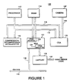
- Fig. 1 shows a block diagram representation of a video processing system including a system and method for accelerating the compression and decompression of digital video signals of the present invention.
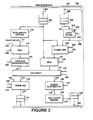
- Fig. 2 shows a block diagram representation of the pipelined architecture of the system and method for accelerating the compression and decompression of video digital signals of the present invention.
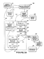
- Figs. 3A,B show a block diagram representation of the data flow of the system and method of Fig. 2 when it is adapted to encode digital video signals and physical buffer memories for use in this process.
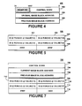
- Fig. 4 shows a block diagram representation of a data structure for the input circular buffer of the encode dataflow of Fig. 3.
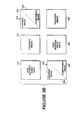
- Fig. 5 shows a block diagram representation of a data structure for the output circular buffer of the encode dataflow of Fig. 3.
- Fig. 6 shows a block diagram representation of the dataflow of the system and method of Fig. 2 when it is adapted to decode digital video signals.
- Fig. 7 shows a block diagram representation of a data structure for the input circular buffer of the decode dataflow of Fig. 6.
- Fig. 8 shows a block diagram representation of a process flow for synchronizing the motion estimation and the encoding process in the system and method of Fig. 2 as well as buffer pointers related thereto.
- Fig. 9 shows a block diagram representation of a process flow for synchronizing the decoding process in the system and method of Fig. 2 as well as buffer pointers related thereto.
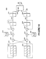
- Fig. 10 shows a block diagram representation of the forward discrete cosine transform computation flow of the encoding portion of the system of Fig. 3.
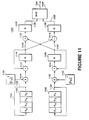
- Fig. 11 shows a block diagram representation of the inverse discrete cosine transform computation flow of the decoding portion of the system of Fig. 3.
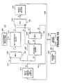
- Fig. 12 shows a block diagram representation of a device for selectably performing either the forward discrete cosine transform of Fig. 10 on the inverse discrete cosine transform of Fig. 11. Fig. 13 shows an arrangement of positions which may
- be selected by the motion estimation method represented by the flowcharts of Figs. 14A-C.
- Figs. 14A-C show flowchart representations of a motion estimation method and an alternate embodiment thereof for use in the data flow of Fig. 3.
- Fig. 15 shows a block diagram representation of a dequantization system which may be used within the system of Fig. 2.
- Fig. 16 shows a more detailed block diagram representation of the various memories and controls associated with the bus interface of the pipelined architecture of system of Fig. 2.
- Fig. 17 shoes a more detailed representation of a frame add/subtract suitable for use in the pipelined architecture of Fig 2.
- Fig. 18 shows a state diagram representation of the operations of the selectable loop filter of Fig. 2.
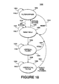
- Fig. 19 shows a more detailed block diagram representation of the adder unit of the selectable loop filter of Fig. 2.
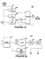
- Fig. 20 shows a more detailed representation of the address unit of the loop filter of Fig. 2.
- Referring now to Fig. 1, there is shown remote
video processing system 100 including compression/decompression accelerator 120. The bus structure of remotevideo processing system 100, includingaddress bus 116 anddata bus 118, permits easy interconnection of the components of a multimedia display system without using a host processor bus. For example, the local video data ofvideo camera 127 may be received byvideo processing system 100 by way ofline 129 and captured, digitized, subsampled and scaled byvideo capture 128. The signals provided byvideo capture 126 may then be processed bysystem 100 for transmission to merge logic video by way ofsystem output line 132 andcapture 128. All of these operations are performed by remotevideo processing system 100 without use of a host processor bus or an industry standard bus such asbus 140 which may coupleremote system 100 to a host computer by way ofbus 138. Becausesystem 100 interfaces a source of video data such asvideo camera 127 tobus 140,system 100 may be understood to be a remotevideo interface system 100. - Within
video processing system 100digital video processor 112 performs software processing whileaccelerator 120 does hardwired functions.Nucleus gate array 121 performs the required memory interface functions. For example,VRAM emulation block 124 makesnucleus gate array 121 function like DRAM with respect to capture 128.Video processing system 100 is therefore limited to the memory configurations supported bynucleus gate array 121. - In a typical configuration of remote
video processing system 100 up to sixteen megabytes of address space may be supported. The first fifteen megabytes of this address space may be reserved for DRAM, for example,DRAM 114, which is interfaced withnucleus gate array 121 byDRAM interface 122. The upper one megabyte of the memory space ofvideo processing system 100 is reserved for communication between various devices which may be coupled to addressbus 116 anddata bus 118. Compression/decompression accelerator 120 may occupy the first one hundred twenty-eight kilobytes of the communication area in the upper one megabyte of memory space. - Compression/
decompression accelerator 120 is not required to decode all of the available one hundred twenty-eight kilobyte address space because the area is well in excess of the requirement for an internal register map.Accelerator 120 may be an initiator or a target in a bus transaction within remotevideo interface system 100. Whenaccelerator 120 initiates actions it fetches thirty-two bit words from memory. Whenaccelerator 120 is a target it responds to all scalar accesses or addresses in its range. - The bus structure of remote
video interface system 100 may use a daisy chain priority scheme for bus arbitration. In this scheme compression/decompression accelerator 120 may request access tobuses nucleus gate array 121. In thepreferred embodiment accelerator 120 is the last connection in the daisy chain it has the lowest priority. Thus, bursts initiated byaccelerator 120 may be aborted in the middle of a burst by another device. This type of abort due to another device typically occurs when a display system controlled bynucleus gate array 121 requires display data. Under such circumstances compression/decompression accelerator 120 must relinquishbuses Accelerator 120later requests buses - Referring now to Fig. 2, there is shown a more detailed block diagram representation of compression/
decompression accelerator 120 of the present invention within remotevideo interface system 100 having a straight pipeline architecture rather than shared resources. Compression/decompression accelerator system 120 may be selectably operated in an encode mode and in a decode mode in accordance with internally generated digital control signals. These two modes are effective to perform and thereby accelerate many encode operations and decode operations performed upon data transmitted by way ofdata bus 118 withinvideo processing system 100. This assists in reaching the video data processing speeds necessary in order to perform real time video. - Data transmitted by way of
data bus 118 of remotevideo interface system 100 is received byaccelerator bus interface 200 of compression/decompression accelerator 120. All RAM withinacceleration 120 must read and write by way ofaccelerator bus interface 200. Whenaccelerator 120 functions in the encoder mode a previous image block, or reference frame, as received byaccelerator bus interface 200 may be stored inloop filter memory 206 orprevious block memory 206. This data may be applied toselectable loop filter 210 for filtering prior to being applied to frame difference block 220 depending upon whetherselectable loop filter 210 is enabled. In the preferred embodimentselectable loop filter 210 may be formed of a small RAM with separate read and write ports, a three stage adder and feedback. - It will be understood that during normal operation of
accelerator 120 data is constantly applied toloop filter memory 206 and constantly read fromfilter memory 206. Thus there is a constant flow of data from acceleratingbus interface 200 to framedifference block 220. The enabling ofselectable loop filter 210 is controlled by loopfilter control line 214.Selectable loop filter 210 ofaccelerator 120, which is enabled by asserting a control signal by way of loopfilter control line 214, may be a two-dimensional 1-2-1 filter applied to the interior of an eight-by-eight pixel block. In the preferred embodiment of compression/decompression accelerator 120 the filter coefficients ofloop filter 210 may be as shown in Table I.
-
Selectable loop filter 210 may be applied to various areas of the stored image inloop filter memory 206. These areas are as shown in Table II. The outer rows and columns of an eight-by-eight pixel block from the image being filtered withinloop filter 210 are filtered only in one direction except at the corners. The pixel positions receiving this filtering in only one direction are indicated by ones in Table II. The pixels at the corners of the pixel block filtered are not affected byselectable loop filter 210. This is indicated in Table II by zeros. The remaining pixels in the interior of the block are filtered in both directions. The pixels which are filtered in two directions are indicated by the twos in Table II.
- The reference frame data of
loop filter memory 206 is applied to frame difference block 220 by way ofreference frame line 209 either with or without filtering byselectable loop filter 210. A frame subtraction is performed indifference block 220 when compression/decompression accelerator 120 performs motion estimation encoding. In the subtraction offrame difference block 220, the information ofreference frame line 209 is subtracted from the current frame information oncurrent frame line 205. The difference between the reference frame data ofline 209 and the current frame data ofline 205 is then provided for encoding at the output offrame difference block 220. The information regarding the current frame line is received frombus interface 200 by way ofcurrent frame memory 204 andline 202. This frame subtraction of frame difference block saturates the resulting image values to a signed number between negative and positive two hundred fifty-five. - The output of
frame difference block 220 is multiplexed withintransform multiplexer 224 with the information applied directly by way ofline 205.Transform multiplexer 224 is controlled bymultiplexer control line 225. It will be understood that the state ofcontrol line 225 depends upon whether the image block being processed is intrablock encoded or motion estimation encoded. The output oftransform multiplexer 224 is then encoded by means of a forward discrete cosine transform operation performed within selectable discretecosine transform block 230 within compression/decompression accelerator 120. Selectable discretecosine transform block 230, or reconfigurable discretecosine transform block 230, may perform either a forward or an inverse discrete cosine transform. The transform performed depends on the control signals applied toselectable transform block 230 by encode/decode control line 226 and forward/inversetransform control line 228. - The transformed data from selectable discrete
cosine transform block 230 is then applied to zig-zag quantization block 238 for quantization in a conventional zig-zag order. It will be understood that the need for intermediate storage is eliminated by quantizing in zig-zag order rather than first arranging the data into zig-zag order and then reading the arranged data intoquantization block 238. This zig-zag quantization ofblock 238 is performed by indexed reading of the data from the matrix of data which is being quantized. This permits true pipelining withinaccelerator 120. - One basic formula for quantization by
quantization block 238 within compression/decompression accelerator 120 of the present invention may be:
- Equation (1)
where value is the quantized value which appears onquantization output line 216 ofquantization block 238, d is the input applied to quantization block 238 byselectable transform block 230, and Q is the quantization multiplier.Accelerator 120 may perform the division operation of Equation (1) by performing a table look up and providing an eight bit value R which is given by the formula:
- Compression/
decompression accelerator 120 then performs the following operation:
- If the coefficient is a DC term and the block is intrablock encoded:


- The quantized output data from zig-
zag quantization block 238 is applied by way ofquantization output line 216 to runlength encoder block 246 for conventional run length encoding within compression/decompression accelerator 120 in order to provide conventional run/value pairs. The run/value output of runlength encoder block 246 is applied to run/value store buffer 248 by way ofencoder output line 242. Transmission of run/value pairs from run/value store buffer 248 to devices external toaccelerator 120 is by way ofaccelerator bus interface 200. - It will be understood that during the encoding process of compression/
decompression accelerator 120 quantized data fromquantization block 238 may also be applied by way ofquantization output line 216 todequantization multiplexer 218 and, therefrom, to zig-zag dequantization block 222. Thus quantization block 238 anddequantization block 222 are directly coupled withinaccelerator 120 by way ofdequantization output line 216. This direct coupling permits dequantization immediately after quantization thereby avoiding the delays of run length encoding and run length decoding. Thus pixels applied toaccelerator 120 may be simultaneously encoded and decoded. - The data of
line 216, which was zig-zag encoded inquantization block 238, is applied to zig-zag dequantization block 222 in a sequence adapted to reestablish the order of the data prior to the zig-zag encoding. This eliminates the need for the intermediate storage which is conventionally required to hold the re-ordered data. Thus, the data which is encoded in selectable discretecosine transform block 230 and zig- zag encoded and quantized inquantization block 238 may be immediately dequantized during the encoding process ofaccelerator 120 bydequantization block 222 by way ofquantizer output line 216. This may be performed without intermediate zig-zag and run length encoding or decoding and without the memory storage requirements associated therewith. - The dequantization operation of
dequantization block 222 may use the formula of Equations (2):

- In this formula value is the quantized input data applied to dequantization block 222 either by
multiplexer input line 216 fromquantization block 238 or bymultiplexer input line 211, Q is the quantization multiplier as previously described, and d is the dequantized result which appears onoutput line 223 ofdequantization block 222. - In a case wherein the transform coefficient corresponds to a DC term and the block being dequantized within
dequantization block 222 is intrablock coded, the dequantization formula is as set forth in Equations (3). The intrablock coding decision is made withinprocessor block 112 and is communicated to dequantization block 202 by way ofINTRA control line 225.
else
- The data which is dequantized within
dequantization block 222 is applied to selectable discretecosine transform block 230 bydequantization output line 223. As previously described,selectable transform block 230 is effective to selectively apply either a forward or a inverse discrete cosine transform to received signals according to transformcontrol line 228. The inverse discrete transform is applied byselectable transform device 230 to the data received from unzig-zag dequantization block 222. - The inverse transformed signal provided by this operation is applied to frame add
block 235 which also receives the reference frame data ofreference frame line 209. Frame addblock 235 adds back in the reference frame data value online 209 which was subtracted out byframe difference block 220 during the encode process. The frame addition of frame addblock 235 saturates its output to a value between zero and positive two hundred fifty-five. The output of frame addblock 234 is stored in decodedblock storage buffer 240. Data which is thus encoded and decoded withinaccelerator 120 is transmitted from decodedblock storage buffer 240 by way ofaccelerator bus interface 200. Thus, while operating in the encode mode compression/decompression accelerator 120 provides both an encoded signal inbuffer 248 and a decoded version of the encoded signal inbuffer 240. This permitssystem 100 to determine the errors which are decoded by a remote system receiving the encoded data. - It will be understood that
frame difference block 220 and frame addblock 235 may be reconfigurations of the same circuitry withinaccelerator 120. Add/subtractblocks control lines - When encode/decode
mode control line 228 adapts compression/decompression accelerator 120 to operate in the decode mode, the data to be decoded is received fromdata bus 118 of remotevideo processing system 100 intoaccelerator bus interface 200. This data to be decoded inbus interface 200 has previously been discrete cosine transformed, zig-zag encoded and run length encoded. It is therefore applied to runlength decoder block 208 withinaccelerator 120. The run length decoded output data ofdecoder 208 is applied by way ofdecoder output line 211 anddequantization multiplexer 218 to dequantization block 222 where it is reordered to undo the effects of zig-zag encoding as previously described. Control ofdequantization multiplexer 218 may be by forward/inversetransform control line 228 alone becausedequantization block 222 receives only the data ofquantizer output line 216 during forward transforms and only the data ofdecoder 208 during inverse transforms. - In order to perform the zig-zag and the unzig-zag operations of
accelerator 120, blocks 222, 238 translate the row order of the transform coefficients, respectively, into the order of increasing spatial frequency. Rearranging the coefficients into this different order is a useful prelude to run length encoding because it tends to group coefficients of similar spatial frequency together. The scanning order of the coefficients used to apply data to quantization block 238 ofaccelerator 120 is set forth in Table III wherein a zig-zag pattern is followed from the upper left to the lower right. The run length encode process ofencoder block 246 is a straight forward compression of the value string to a group of run/value pairs. The run length is calculated by counting up to but not including the value.
- Run length decoded data from run
length decoder block 208 is applied by way ofmultiplexer input line 211 anddequantization multiplexer 218 to dequantization block 222 where it is dequantized.Dequantization multiplexer 218 may be under the control of forward/inversetransform control line 228 only as previously described. The dequantized data fromdequantization block 222 is then applied to selectable discretecosine transform block 230. Dequantization/quantization blocks 222, 238 are configured to perform the dequantization operation ofblock 222 under the control of encode/decode control line 226. - It will be understood that
dequantization multiplexer 218 is controlled to selectmultiplexer input line 211 for application toselectable transform device 230 when compression/decompression accelerator 120 is operating in the decode mode and to selectquantization output line 216 at the appropriate times whenaccelerator 120 is operating in the encode mode. Thusdequantization multiplexer 218 selects the externally encoded data frombus interface 200 when in the decode mode and the internally encoded data otherwise. This selection bymultiplexer 218 is controlled by forward/reverse control line 228. - Thus, it will be understood that compression/
decompression accelerator 120 is a pipelined architecture which may be divided into two parallel pathways, one form encoding and one for decoding. The encoding pathway receives a previous image and a current image intobuffers frame difference block 220 to selectable discretecosine transform block 230. During this portion of the encode operation, discretecosine transform device 230 operates in the forward transform mode. The remainder of this encode pathway ofaccelerator 120 includesblocks transform device 230, perform further encoding operations, and store the encoded data inbuffer 248. - When compression/
decompression interface 120 operates in the decode mode, the other parallel pathway of its pipeline architecture is used. This other parallel pathway includes run length decoding and dequantization inblocks discrete cosine block 230 which operates in the inverse transform mode when the decode pathway is active. The inverse transform data is frame added and stored inbuffer 240. - Finally, it will be understood that data may be applied from one pathway to the other during the encode mode as previously described. This occurs when quantized data on
quantizer output line 216 of the encode parallel pathway is applied to dequantization block 222 in order to provide the companded image. Thus block 238 may be substantially directly coupled to block 222 withinaccelerator 120. For example, blocks 222, 238 may work on the same block of physical memory withinaccelerator 120, withblock 222 working just a few pixels behindblock 238. - Referring now to Figs. 3A,B, there are shown encode
dataflow 300 for performing the encoding of data within compression/decompression accelerator 120 of the present invention and physical memory buffers 350, 352, 354. Within encodedataflow 300current image block 302 is applied tomotion estimation block 112a for a coding decision in order to permitsystem 100 to transmit as little data as possible. For this purpose, it will be understood that it is sometimes more efficient to estimate the displacement between one frame and the next and transmit only the displacement. This is understood to be motion estimation encoding. However, if there is a great deal of difference between frames, it is less efficient to transmit the displacement and the block is encoded based only upon itself. This is understood to be intrablock encoding. This determination, and therefore the determination whether to applyloop filter 210, is made by softwarecoding decision block 112a. - Thus, within
motion estimation block 112a a determination is made whethercurrent image 302 is to receive intrablock encoding or motion estimation encoding. Execution then proceeds to compression/decompression accelerator 120 by way ofline 312. If motion estimation is to be performed a pointer to the block to be encoded is stored in encode inputcircular buffer 322 which may be located inmemory 114. Thus, it will be understood that during encode dataflow 300 pointers, rather than image data, reside in encodecircular buffer 322 and thatdataflow 300 represents a loosely coupled system. Within encode input circular buffer 322 a pointer tocurrent image block 322 is stored for applyingcurrent image block 322 to compression/decompression accelerator 120 for motion estimation encoding. -
Frame difference block 220 withinaccelerator 120 receives the previous block and the data ofcurrent image block 326. A difference is determined within frame difference block 220 as previously described. A forward discrete cosine transform is then performed on the data fromframe difference block 220 in encodedataflow 300 by forward discretecosine transform block 230a. It will be understood that the function of forward discretecosine transform block 230a may be performed by selectable discretecosine transform block 230 whenselectable transform block 230 operates in the forward mode as determined bytransform control line 228. - The transformed data from forward discrete
cosine transform block 230a is received byquantization block 238 in a conventional zig-zag order as previously described and quantized therein. The quantized data fromblock 238 is applied by way ofquantization output line 216 to runlength encoder 246 for run length encoding. Run length encoding withinencoder 246 provides conventional run/value pairs as known to those skilled in the art. The run/value pairs fromrun length encoder 246 are applied, by way ofline 330, to encode outputcircular buffer 332. - The data within encode output
circular buffer 332 is then applied tovariable length encoder 112b to providecompressed bit stream 338. It will be understood thatbuffer 332 may be located inmemory 114 and thatvideo processor 112 may read the run/value pairs frommemory 114 in order to perform the operations ofvariable length encoder 112b. Thus, the motion estimation decision ofmotion estimation block 112a and the variable length encode ofvariable length encoder 112b may both be performed byvideo processor 112 ofsystem 100. A video processor system suitable for this purpose is the 82750 PB made by Intel Corporation. - It will thus be understood that the operations of both
motion estimation block 112a and variable length encode 112b may be performed by this video processor system. Thus the functions of encodedataflow 300 are partitioned as follows: (1) the software functions including motion estimation and Huffman encoding are performed byvideo processor 112, and (2) the remaining functions, in particular functions which would be computationally intensive are hardwired in circuitry withinaccelerator 120. These partitioned functions ofprocessor 112 andaccelerator 120 are synchronized within remotevideo processing system 100. - The quantized data from
quantization block 238 is also applied to dequantization block 222 by way ofquantization output line 216. The data transferred in this manner within compression/decompression accelerator 120 thus bypasses both run length encoding within runlength encoder block 246 and run length decoding within runlength decoder block 208. Thus, the process of decoding the encoded data in order to provide a companded image may be performed without the additional memory reads and writes involved in performing run length encoding and run length decoding. These savings provide a significant advantage in real time calculations. It will be understood by those skilled in the art that the operations of run length blocks 208, 246 are not lossy operations and that their contribution to the motion estimation decoding decision ofmotion estimation block 112a may therefore be ignored. - Inverse discrete
cosine transform block 230b applies an inverse transform to the dequantized data received fromdequantization block 222. It will be understood that the operations of inverse discretecosine transform block 230b of encodedataflow 300 may be performed by selectable discretecosine transform block 230 whentransform block 230 operates in the inverse mode under the control oftransform control line 228. Thus during the encode mode of compression/decompression accelerator 120, as described by encodedataflow 300,selectable transform block 230 functions both as a forward and an inverse discrete cosine transform under the control of forward/inversetransform control line 228. - The decoded signal from
inverse transform block 230b is applied to frameaddition block 235, and, therefrom, to current/compandedimage block 302 by way ofline 328. It will be understood that the signal ofline 328 resulting from encoding and decoding within encodedataflow 300 ofaccelerator 120 is the image which is compared with the previous image ofprevious image block 314 in order to make the motion estimation coding decision ofblock 112a. A useful and advantageous feature of encodedataflow 300 is thatcurrent image 326 is overwritten by the decoded image ofline 328 thereby eliminating the need for separate buffers storing the same images. Thus portions of the companded image and portions of the current image are present simultaneously in the same block of memory which may thus simultaneously perform the functions of bothblocks - The operation of
blocks physical buffers memory video processing system 100 digitized image data fromcamera 127 may be stored first inphysical buffer memory 350 whilephysical buffer memory 352 stores the previous image.Physical buffer memory 354stores portion 358 of the current image which is in the process of being overwritten by the compandedportion 356. - When an entire digitized image is stored in
buffer memory 350 and an entire companded image is stored inphysical memory 354, the functions of physical buffer memories are redefined. The digitized data inphysical memory 350 is used as thecurrent image 362 which is overwritten bycompanded data 360. The companded data ofphysical memory 354 is used as the previous image for motion estimation byblock 112a. New digitized data is stored inphysical memory 352. This process continues withphysical memory 354 next serving to collect new digitized data. In this manner three, rather than four blocks of physical memory may be used to perform these operations of encodedataflow 300. - Referring now to Fig. 4, there is shown encode input
buffer data structure 400 for controlling blocks of data stored in encode inputcircular buffer 322 as required within encodedataflow 300. Within encode inputbuffer data structure 400control word 402 is provided. When motion estimationcoding decision block 112a determines how an image should be encoded a bit withincontrol word 402 may be used to indicate whether the block is intrablock encoded or a motion compensation encoded. Other parameters associated with each block of data may also be stored incontrol word 402 ofdata structure 400. Another example of the type of information which may be stored withincontrol word 402 is information on whetherselectable loop filter 210 is enabled or disabled. Additionally the five-bit quantization/dequantization value Q ofblocks control word 402 of encode inputbuffer data structure 400. - Encode input
buffer data structure 400 also contains original imageblock address pointer 404. Original imageblock address pointer 404 points to the original location of a block of data incurrent image block 326. It will be understood that originalimage block pointer 404 also points to current/compandedimage block 302 when image blocks 302, 326 are in the same physical memory because the companded image received by way ofline 328 overwrites the current image. Thus the image being encoded is the original image which may be the same as the current image. It will also be understood thatpointer 404 points to fixed length data rather than variable length data because the image ofblock 302 is not yet encoded. Previous imageblock address pointer 406 points to the location of the previous image inblock 314. - Referring now to Fig. 5, there is shown encode output
buffer data structure 500 for encode outputcircular buffer 322 within encodedataflow 300. In the preferred embodiment of compression/decompression accelerator 120 two input run/value pairs such as run/value pairs 501, 503 may be stored in a thirty-two bit double word of inputcircular buffer 322, such asdouble words Double word 506 of inputcircular buffer 322 is filled with ones to indicate the end of a list of run/value pairs. When there is an odd number of run/value pairs in the list ofbuffer data structure 500 one word ofdouble word 506 may be used to store a run/value pair and the remaining word may be filled with ones to indicate the end of the list. - Referring now to Fig. 6, there is shown
decode dataflow 600 using compression/decompression accelerator 120 of the system of the present invention.Compressed bit stream 601 is received and decompressed withindecode dataflow 600.Compressed bit stream 601 may be a bit stream such ascompressed bit stream 338 provided by encodedataflow 300 of the present invention. A variable length decode is performed upon receivedbitstream 338 byvariable length decoder 112c. It will be understood thatvariable length decoder 112c ofdecode dataflow 600 andvariable encoder 112a of encodedataflow 300 may be performed by a single dual purpose encoding and decoding device withinvideo processing system 100 such asprocessor block 112. The decoded data of variable length decoder 602 is then placed into decode inputcircular buffer 606 ofdecode dataflow 600. -
Frame difference block 220, forwarddiscrete cosine transform 230a,quantization block 246 and runlength encoder 246 are not used within compression/decompression accelerator 120 whenacceleration 120 operates in the decode mode. When operating in thedecode mode accelerator 120 receives the data for decoding according to decode dataflow 600 from decode inputcircular buffer 606. In particular,run length decoder 208 ofaccelerator 120 receives the data fromcircular buffer 606. The data decoded withinrun length decoder 208 is then applied to dequantization block 222 for a dequantization withinaccelerator 120. This data is applied to dequantization block 222 in an order which is adapted to restore the sequence of the data prior to zig-zag encoding by a zig-zag encoder within an external device which transmits encoded data toaccelerator 120. - An inverse discrete cosine transform is applied to the dequantized data of
block 222 by inverse discretecosine transform block 230b. It will be understood that the operations of inverse discretecosine transform block 230b withindecode dataflow 600 may be performed byselectable transform block 230 whenselectable transform block 230 is in the inverse mode as determined bytransform control line 228. -
Previous image block 604 is received by compression/decompression accelerator 120 by way ofline 203. The receivedprevious image block 604 is stored inprevious block memory 206 withinaccelerator 120. Ifselectable loop filter 210 is enabled under the control offilter control line 214 the image inprevious block memory 206 is filtered and applied to frame addblock 234. Ifselectable loop filter 210 is not enabled the image withinprevious block memory 206 is applied directly to frame addblock 234. When theprevious image block 604, as received fromprevious block memory 206, and the dequantized transformed current image block are added in frame addblock 234, the output ofblock 234 is stored in decodedimage block 608. - Referring now to Fig. 7, there is shown decode input circular
buffer data structure 700 for decode inputcircular buffer 606 ofdecode dataflow 600. It will be understood that the data of decode inputcircular buffer 606 is variable length data if Huffman encoding is performed before transmission to buffer 606. Decode inputbuffer data structure 700 containscontrol word 702 which may be used to store the quantization/dequantization value Q as well as information regarding whetherselectable loop filter 210 is enabled or disabled. Additionally controlword 702 may contain information regarding whether the image block being decoded bydecode dataflow 600 is a intracoded block or a motion compensated block. Currentimage block address 704 ofdata structure 700 points to the beginning of a current image andprevious image block 706 points to the previous image. - Additionally, in the preferred embodiment of
data structure 700 two run/value pairs, such as run/value pairs 710, 712, may be stored in each of a number of double words such asdouble words Double word 716 ofcircular buffer 606 is filled with ones to indicate the end of the list of run/value pairs. If there is an odd number of run/value pairs in the list of pairs, one word ofdouble word 716 may be used to store a run/value pair and the remaining word may be filled with ones to indicate the end of the list. - It will be understood that motion estimation
coding decision block 112a performs the motion estimation process within encodedataflow 300. Additionally, it performs the variable length encode of the local image and the variable length decode of remotecompressed bit stream 601. Thus, the functions ofblock 112a may be performed by a general purpose video processor such asvideo processor 112. Compression/decompression accelerator 120 of the present invention performs all of the remaining functions of encodedataflow 300 and decodedataflow 600. -
Video processor 112 andaccelerator 120 of remotevideo processing system 100 operate substantially independently of each other. However, they tend to work from common areas of memory to implement operations such as accesses to the various circular buffers. The manner in which the work load of remotevideo processing system 100 is partitioned betweenvideo processor 112 and compression/decompression accelerator 120 minimizes the overhead required for synchronization of the various dataflows such asdataflows video processing system 100. Thus, there must be a method withinvideo processing system 100 to manage memory such that buffer overflows and underflows due to conflicts betweenvideo processor 112 andaccelerator 120 are avoided. - In order to minimize costly fine tuning of synchronization within remote video interface system 100 a pointer interlock scheme is used for reading and writing the run/value data in encode
dataflow 300 and decodedataflow 600. To implement this scheme both an encode synchronization and a decode synchronization are provided within remotevideo processing system 100 containing compression/decompression accelerator 120. - Referring now to Figs. 8, 9, there are shown input circular
buffer synchronization flow 800 and output circularbuffer synchronization flow 900, as well as various buffer pointers for use in circular buffer synchronization flows 800, 900. It will be understood thatvideo processor 112 of remotevideo interface system 100 controls synchronization of access tobuffers video processing system 100 buffers in accordance with input/output synchronization flows 800, 900. During the encoding process of encodedataflow 300 compression/decompression accelerator 120 reads block lists of uncompressed image data from encode inputcircular buffer 322.Accelerator 120 also writes compressed data in the form of run/value pairs into encode outputcircular buffer 332 withindataflow 300 as previously described. Access byaccelerator 120 to the physical memory storingcircular buffers - Therefore, in order to avoid conflicts, whenever a reset or some other initial condition occurs within
video processor 112 and compression/decompression accelerator 120 first the pointers of one pair of input buffer pointers are set equal to each other and then the pointers of a second pair of output buffer pointers are set equal to each other.Accelerator INRPTR pointer 804b, which indicates the next location from whichaccelerator 120 will read inputcircular buffer 322, is set equal toaccelerator INEPTR pointer 804c, which indicates the next location afterend location 804 ofcurrent input list 812. - Compression/
decompression accelerator 120 then sets the two output buffer pointers equal to each other. Accelerator OTWPTR pointer 830c, which indicates the next location to whichaccelerator 120 will write in outputcircular buffer 322, is set equal to the value of accelerator OTEPTR pointer 830e, which indicates the location after the end of the current output list. - The beginning and the end of both the current input list are thus equal to each other and the beginning and end of the current output list are thus equal to each other. This defines their stall condition. Therefore, processing by compression/
decompression accelerator 120 within encodedataflow 300 is suspended. It should be noted, however, thatbus interface 200 ofaccelerator 120 may continue to operate becauseaccelerator 120 may be a target in a bus transaction of remotevideo interface system 100. However,accelerator 120 does not initiate any transactions in this suspended state. - After the above pairs of buffer printers are set equal to each other,
video processor 112 defines the areas of encode inputcircular buffer 322 and encode outputcircular buffer 332. These buffers are defined by setting a series of memory mapped pointers within compression/decompression accelerator 120 using scalar memory write operations. These pointers includeaccelerator INCSTR pointer 804a andaccelerator INCEND pointer 804d which indicate the location after beginningaddress 803 and the location after endingaddress 805, respectively, of encode inputcircular buffer 322. Additionally,accelerator pointers OTCSTR 840a,OTCEND 840d are set byvideo processor 112. - It will be understood that
video processor 112 must setaccelerator pointers 804a,c,d equal toprocessor pointers 820a,c,d so thataccelerator 120 and block 112 may agree regarding wherecircular buffer 322 begins and ends and wherecurrent list 812 ends. Thus, for example, aftervideo processor 112 writes one or more blocks of data, and updates itsown write pointer 820e in a post increment manner, it updatesaccelerator pointer INCEND 804d. -
Processor INWPTR pointer 820e indicateslocation 806 withinbuffer 322.Location 806 is the location to whichvideo processor 112 is writing and it has no corresponding pointer within compression/decompression accelerator 120 becauseaccelerator 120 does not write to buffer 322.Accelerator INRPTR 804b andprocessor INRPTR 820b withinvideo processor 112 indicate the next location at whichaccelerator 120 will read inputcircular buffer 322 and thus will differ from each other. -
Processor block 112 then starts motion estimation and block classification on each block of pixels in accordance with the determinations previously described with respect to encodedataflow 300.Video processor 112 then writes the pointers associated with each block of externally stored image data into inputcircular buffer 322, starting with the address indicated byINWPTR pointer 820e. - In the case of a decode of a
remote bitstream 601, compression/decompression accelerator 120 reads input data from decode inputcircular buffer 606 and writes reconstructed data into a frame memory such as decodedimage block 608. Under initial conditions, including a reset,accelerator 120 sets two input buffer pointers equal to each other.Accelerator INRPTR pointer 804b, which indicates the position from whichaccelerator 120 is reading inputcircular buffer 606, is set equal toaccelerator INEPTR pointer 804c, which represents the end of the current input list. -
Video processor 112 then defines the areas of encode inputcircular buffer 606 and encode outputcircular buffer 608 by setting a series of memory mapped pointers on compression/decompression accelerator 120 using scalar memory write operations. This may be the only time whenvideo processor 112 writes toaccelerator 120. These pointers includeINCSTR pointer 804a andINCEND pointer 804d which indicate the beginning and ending addresses, respectively, of encode inputcircular buffer 322.Video processor 112 then starts the variable length decode process on the compressed data and writes the run/value block data to the circular buffer area. - When enough data is written into the buffer area,
processor 112 updates bothINEPTR pointers decompression accelerator 120 and inprocessor 112.INEPTR pointers decompression accelerator 120 then begins to fetch data at the location programmed intoaccelerator INRPTR pointer 804b and continues up to but not including the location programmed intoaccelerator INEPTR pointer 804c. WhenINRPTR pointer 804b equalsINEPTR pointer 804c, compression/decompression accelerator 120 stops processing. -
INRPTR pointer 804b wraps around topointer INCSTR 804a when it reaches the address programmed intoaccelerator INCEND pointer 804d.Video processor 112 is responsible for maintaining bothINEPTR pointers decompression accelerator 120 is responsible for maintainingaccelerator INRPTR pointer 804b.Video processor 112 updates its copy ofINRPTR pointer 820b by readingaccelerator INRPTR pointer 804b within compression/decompression accelerator 120. -
Video processor 112 may write additional blocks into inputcircular buffer 322 by writing the data then updatingaccelerator NEPTR pointer 804c. Whenvideo processor 112 writes this data,accelerator INRPTR pointer 804c is also read. This is required in order to preventvideo processor 112 from overwriting areas of the circular buffer. This defines the stall condition for a device writing into the circular buffer when its read and write pointers are the same. It will be understood that it is also the responsibility ofvideo processor 112 to update the pointers ofaccelerator 120 during output to outputcircular buffer 332.Accelerator 120 updates its own end pointer and write pointer andvideo processor 112 must read the updated pointers. - Referring now to Figs. 10, 11, there are shown forward discrete cosine
transform computation flow 1000 and inverse discrete cosinetransform computation flow 1100 of the present invention. Discrete cosinetransform computation flows transform blocks 230a,b respectively ofdataflows transform computation flows selectable transform block 230 under the control of forward/inversetransform control line 228. - The operation of forward discrete cosine
transform computation flow 1000 as performed bytransform block 230a of encodedataflow 300 or selectable discretecosine transform block 230 of compression/decompression accelerator 120 may be expressed as shown in Equation (4):
- In Equation (4) matrix [X] is the input data matrix applied to transform block 230 or transform
block 230a, matrix [C] is the discrete cosine transform matrix, and matrix [4)] is the transformed output matrix which is applied to transformoutput line 236 bytransform block 230. - Inverse discrete cosine
transform computation flow 1100 as performed bytransform block 230 or by selectable discretecosine transform block 230 under the control oftransform control line 228 may be expressed shown in Equation (5):
- In Equation (5) matrix [4)] is the transformed input matrix received by way of
transform input line 223, matrix [X] is the output matrix applied to transformoutput line 234, and matrix [C]T is the inverse discrete cosine transform matrix. - The individual coefficients cm of the discrete cosine transform matrix [C] may be expressed as:

- In Equation (6) N is the order of the discrete cosine transform performed within
transform computation flows values - Solving Equation (6) when the order N of the discrete cosine transform is eight yields the following discrete cosine transform coefficients cm:

- Under these circumstances the discrete cosine transform matrix [C] of Equation (4) may be formed in accordance with Equation (6) and Equations (7) as follows:

- It will be understood that eight multiply/accumulate operations are required to perform this transform for each data point within input data matrix [X]. Therefore 64 x 8 = 512 multiply/accumulate operations are required for a one-dimensional discrete cosine transform. For a two-dimensional
discrete cosine transform 1024 multiply/accumulate operations are required. - Several fast prior art algorithms are known for performing the forward and inverse discrete cosine transforms of Equation (4) and Equation (5). Using certain of these prior art methods an eight point discrete cosine transform may be performed with twelve multiplies and twenty-nine adds. Thus a total of one hundred ninety-two multiplications and four hundred sixty-four additions are required thereby simplifying the operation of these transforms. These algorithms are better suited for parallel operation.
- Forward discrete
cosine transform flow 1000 of the present invention executes a fast forward discrete cosine which is a faster and more efficient variation of the transform represented by Equation (4). In forward discretecosine transform flow 1000, the order N of the transform is eight. It will be understood by those skilled in the art that the transform performed byforward transform flow 1000 is a fast forward transform of the type described with respect to transformblock 230a. It is performed by selectable discretecosine transform block 230 whenselectable transform block 230 is in the encode mode. This fast forward transform may be expressed as:

wherein the elements of submatrices [CA] and [CB] are obtained from the discrete cosine transform matrix using sparse matrix factorization techniques known to those skilled in the art and the coefficients of Equations (8) are given by:


- The elements of vectors [X'] and [X"] or submatrices [X'] and [X"] are formed by respectively adding and subtracting the high order data points of matrix [X] and the low order data points of matrix [X].
- Transform
computation flow 1000, performed by selectable discretecosine transform block 230, is effective to receive the input data matrix [X] and apply the forward discrete cosine transform matrix [C] to input data matrix [X] to provide the forward transformed matrix [Φ] as set forth in Equation (4) and Equations (8). In order to perform these operations the low order data points x0-x3 of an input word x are selected to form a subword. These data points may be any number of bits wide. The data points of this subword are placed into circular input registers 1006. Similarly, the high order data points x4-x7 of the input word are selected to form another subword. The data points of this subword are placed into circular input registers 1032. - As data points x0-x3 are successively applied to
addition node 1008 andsubtraction node 1036 they are also applied to the input ofcircular registers 1006 by way of a loop formed byregister output line 1004. Similarly, data points x4-x7 are successively applied to the input ofcircular registers 1032 by way of a loop formed byregister output line 1030 as they are applied toaddition node 1008 andsubtraction node 1036. - The timing of the presentation of each of these data points is controlled in a manner understood by those skilled in the art to provide the sums xo +x7, x1 +x6, x2 +xs, and x3 + X4, which are the elements of submatrix [X'] of Equations (8), at the output of
addition node 1008. In a similar manner the differences xo- X7, x1-x6, X2-X5, x3-x4, which are the elements of submatrix [X"] of Equations (8), are formed at the output ofsubtraction node 1036. It will be understood that, acting cooperatively, registeroutput lines nodes flow 1000, these inputs proceed through inputcircular buffers nodes multiplication nodes transform computation flow 1000. - The coefficients of submatrix [CA] are applied to submatrix [X'] received by
multiplication node 1014 fromaddition node 1008 for multiplication withinnode 1014 in accordance with Equations (8). The coefficients of the submatrix [CA] are applied tomultiplication node 1014 bycoefficient register 1010. The matrix partial product terms thus formed bymultiplication node 1014 are then applied toaddition node 1016 withintransform computation flow 1000. - In a similar manner submatrix [X"] received by
multiplication node 1040 fromsubtraction node 1036 is multiplied withinnode 1040 by the coefficients of submatrix [CB] in accordance with Equations (8). The coefficients of submatrix [CB] are applied tomultiplication node 1040 bycoefficient register 1042. The matrix partial product terms thus formed bymultiplication node 1040 are applied toaddition node 1044 withintransform computation flow 1000. - The sums formed by
addition nodes blocks transform computation flow 1000. The outputs ofregister blocks addition nodes register output lines nodes computation flow 1000 to perform the additions of the partial product terms as required by the matrix algebra operations of Equations (8). - The output of
register blocks blocks transform computation flow 1000 which may be implemented by selectable discretecosine transform block 230. It will be understood that the output ofregister block 1024, which appears onregister output line 1026, is the set of even numbered transformed data points Ø6, 04, 02, Ø0 of Equations (8). Additionally, it will be understood that the output ofregister block 1050, which appears onregister output line 1052, is the set of odd numbered transformeddata points register output lines output multiplexer 1054 in order to be multiplexed, reordered and applied by way of the forwardflow output line 236. It is believed that performing a fast forward discrete cosine transform using the system and method ofcomputation flow 1000 provides a transformed output signal several clock cycles faster than the known prior act. - In this manner the transform of
computation flow 1000 may be performed by applying asingle multiplier circular buffers lines circular buffers buffers - In a similar manner inverse discrete cosine
transform computation flow 1100 of the present invention executes a fast inverse discrete cosine transform wherein the order N of the transform is eight. It will be understood by those skilled in the art that the transform performed by forwardtransform computation flow 1100 is the type of transform performed by selectable discretecosine transform block 230 whentransform block 230 is in the decode mode. This inverse discrete cosine transform matrix [C]T may be mathematically expressed as:

wherein the submatrices [CA]T and [CB]T are obtained from the discrete cosine transform matrix using sparse matrix factorization techniques. -
Computation flow 1100 of selectable discretecosine transform block 230 is effective to receive an inverse transformed matrix [Φ] and apply an inverse discrete cosine transform matrix [C]T to provide an output data matrix [X].Computation flow 1100 is adapted to be a much faster variation of the transform set forth in Equation (4) and Equations (9). In order to perform these operations the even transformed data points Ø0, 02, Ø4, 06, of the values of transformed matrix [Φ] are placed incircular input registers 1106 and the odd transformed data points Ø1, 03, 0s, Ø7 reside in circular input registers 1132. - As even transformed data points Ø0, 02, Ø4, 06 residing in circular input registers 1104 are successively applied to
multiplication node 1114 they are simultaneously applied to the input ofcircular registers 1106 byregister output line 1104. As odd numbered transformed data points Ø1, 03, 0s, 07, of circular input registers 1132 are applied tomultiplication node 1140 they are also simultaneously applied back to the input ofcircular registers 1130 by way of a loop formed byregister output line 1130. - The value applied to
multiplication node 1114 frominput registers 1106 is multiplied withinmultiplication node 1114 by the coefficients of submatrix [CA]T in accordance with Equations (8). The coefficients submatrix [CA]T are applied tomultiplication node 1114 bycoefficient register 1110. The product formed bymultiplication node 1114 is then applied toaddition node 1116. - In a similar manner the value received by
multiplication node 1140 frominput registers 1130 is multiplied withinnode 1140 by the coefficients of submatrix [CB] T in accordance with Equations (8). The coefficients of submatrix [CB]T are applied tomultiplication node 1140 fromcoefficient register 1142. The product thus formed bymultiplication node 1140 is applied toaddition node 1144. - The sums formed by
addition nodes blocks transform computation flow 1100. The outputs ofregister blocks addition nodes register output lines transform computation flow 1100. - The output of
register blocks addition node 1122 and subtraction node 1148 by way ofregister output lines addition node 1122 and subtraction node 1148 are then applied to registerblocks transform computation flow 1100 which may be implemented by selectable discretecosine transform block 230. - It will be understood that the output of
register block 1124, which appears onregister output line 1126, includes the low order bits xo, x1, x2, x3 of Equations (9). Additionally, it will be understood that the output ofregister block 1150, which appears online 1152, includes the high order data points x4, x5, x6, x7 of Equations (9). The values oflines output multiplexer 1154 in order to be multiplexed and reordered to be applied to frame add 235 by way ofoutput line 234. - Referring now to Fig. 12, there is shown a block diagram representation of selectable discrete
cosine transform block 230 of compression/decompression accelerator 120. It will be understood that selectable discretecosine transform block 230 is effective to perform the operations of both forward discrete cosine transformcomputational flow 1000 and inverse discrete cosine transformcomputational flow 1100 depending upon the control signal applied by way oftransform control line 228. - When compression/
decompression accelerator 120 performs the operations of encodedataflow 300,selectable transform block 230 performs both the operations offorward transform block 230a andinverse transform block 230b. Which transform is performed depends on whether the data ofmultiplexer 224 is being encoded or the data ofdequantizer 222 is being decoded. It is the operations upon the data ofmultiplexer 224 which are represented by forward discrete cosine transformcomputational flow 1000. When performing the operations of encodedataflow 300 relevant toinverse block 230b compression/decompression accelerator 120 provide both an encoded data stream and an image representative of the decoding of the encoded data stream. Whenaccelerator 120 performs the operations ofdecode dataflow 600, selectable discretecosine transform block 230 performs the operations ofinverse transform block 230b as described with respect to inversecomputational flow 1100. These selectable forward and inverse transform operations are determined by the signal applied toselectable transform block 230 by way oftransform control line 228 as previously described. - Within selectable discrete
cosine transform block 230 data fromblock memory 1242 is applied by way ofdata bus 1238 to input data buffer/shifter 1212. Input data buffer/shifter 1212 is effective to arrange and order input data either as shown with respect to inputcircular registers circular buffers cosine transform block 230. - The correctly ordered output of input data buffer/
shifter 1212 is applied by way ofline 1214 tomultiplexers transform control line 228 which selects the encode and decode modes ofselectable transform block 230 as previously described. The signal oftransform control line 228 is determined according tocontrol logic 1240.Control logic 1240 provides a logic level representative of the operating mode of compression/decompression accelerator 120 according to determinations made byprocessor block 112 in a manner understood by those skilled in the art. - When
selectable transform block 230 is in the inverse mode, transformcontrol line 228 causesarray input multiplexer 1208 to select the data ofmultiplexer line 1214 and apply the data ofline 1214 to multiplier/accumulator array 1210. Thus the input data from buffer/shifter 1212 is applied substantially directly to multiplexer/accumulator array 1210 whenselectable transform block 230 is in the decode mode. The coefficient matrices [CA] T and [CB] T are then applied toarray 1210 fromcoefficient registers 1204 in order thatarray 1210 may perform the operations of Equations (9) as previously described with respect toinverse computation flow 1100. Transformed data inoutput data buffer 1230 may be transmitted to blockmemory 1242 by way ofbus 1238. - When selectable discrete
cosine transform block 230 is in the encode mode, the data selected byarray input multiplexer 1208 to be applied to multiplier/accumulator array 1210 is the data onmultiplexer input line 1220 rather than the data onmultiplexer input line 1214. The data onmultiplexer input line 1220 is the output ofbutterfly adder 1218 or add/subtractdevice 1218. Butterfly adder receives as its input either (1) the data from input data buffer/shifter 1212 by way ofline 1214, or (2) the output of multiplier/accumulator array 1210. Which of these two data streams is applied tobutterfly adder 1218 is determined bymultiplexer 1234 under the control oftransform control line 228. - Thus the operations performed upon input data by
selectable transform block 230 prior to multiplication by the transform coefficients, as previously described with respect toaddition node 1008 andsubtraction node 1036, may be performed withinselectable transform block 230 whenselectable transform block 230 is in the forward mode. This also performs the operations of the feedback loops formed byregister output lines addition nodes - It will therefore be seen that the arithmetic operations of
butterfly adder 1218 may be applied directly to the input data points provided by buffer/shifter 1212. Alternatively,adder 1218 may be applied to the input data points provided by buffer/shifter 1212 after the input has been operated upon by the transform coefficients ofarray 1210. Which of these configurations is provided depends on whetherselectable transform block 230 is in the mode for performing a first discrete cosine transform or the inverse of the first discrete cosine transform. It will also be seen that in either mode all functional elements withintransform block 230 are used and there is thus no wasted hardware. - For example, the same hardware elements within
transform block 230 may serve both asregisters 1006 and asregisters 1106, asregisters 1032 and registers 1132. These registers together may formbuffer 1212. Similarly, the same hardware elements withintransform block 230 may serve both asadder 1008 and asadder 1122, assubtractor 1036 and subtractor 1148. These arithmetic elements operating cooperatively may serve asbutterfly adder 1218. Likewise coefficient matrices [CA] and [CA]T may be the same hardware circuitry which is merely accessed differently depending on the mode ofselectable transform block 230. - Thus
selectable transform block 230 requires two multipliers and four adders to perform either the forward or inverse discrete cosine transform. Either of these transforms can be performed bytransform block 230 in sixteen clock cycles. It will be understood that this time may be cut in half by providing two multipliers to operate upon the outputs of eachbuffer buffer - Referring now to Fig. 13, there is shown stepping
direction chart 1300.Stepping direction chart 1300 represents a center position Pc surrounded by four positions P1-P4 along with a plurality of stepping directions 1302-1316. Stepping directions 1302-1316 represent the directions that positions Pc, P1-P4 may move from one frame to another frame during a display of remotevideo processor system 100. For example, if positions Pc, P1-P4 of steppingdirection chart 1300 move directly upwards from one frame to the next, steppingdirection 1302 represents their displacement. If positions Pc, P1-P4 move directly to the right, their motion is represented by steppingdirections 1306.Stepping direction 1304 represents the motion of position Pc, P1-P4 when the positions of steppingdirection chart 1300 move to the upper right. In the manner, eight different directions are represented by stepping directions 1302-1316 of steppingdirection chart 1300. - Referring now to Figs. 14A-C, there is shown a flow chart representation of
motion estimation method 1400. Also show is a representation ofmotion estimation method 1440 which is an alternate embodiment ofmotion estimation method 1400. The function ofmotion estimation methods Motion estimation methods motion vector chart 1300 to determine which stepping direction 1302-1316 best represents the motion of positions Pc, P1-P4 from one frame to another. It will be understood that bothmotion estimation methods encoding dataflow 300 of remotevideo processing system 100 of the present invention. - Operation of
motion estimation method 1400 begins with a determination indecision 1402 whether center position Pc or position P1 of the current frame is a better match with the center position of the previous frame. This determination, as well as the determination of each of the remaining candidate positions tested inmethod 1400, requires a comparison of two hundred fifty-six pixels values of a sixteen- by-sixteen pixel block in the preferred embodiment of encodedataflow 300. If position P1 is a better match than center position Pc the best horizontal position PH is determined to be position P1 as shown inblock 1404 bymotion estimation method 1400. - If position P1 is not a better match than position Pc a determination is made in
decision 1406 whether position P2 is a better match with the center position of the previous frame than center position Pc of the current frame. If position P2 is a better match than center position Pc the best horizontal position PH is made equal to position P2 as shown inblock 1408. If neither position P1 nor position P2 is a better match than center position Pc then center position Pc is selected as the best horizontal position VH as shown inblock 1410. Thus, when operation ofmotion estimation method 1400 arrives atpoint 1411, a determination has been made which of the three horizontal positions Pc, P1, P2 of the current frame has the greatest improvement from the center position. The best horizontal position PH is the one determined to be the best match. - A determination is then made within
motion estimation method 1400 whether position P3 is a better match than center position Pc indecision 1412. If position P3 is a better match it is selected as the best vertical position Pv as shown inblock 1414. If position P3 is not a better match than center position Pc a determination is made indecision 1416 whether position P4 is a better match than center position Pc. If position P4 is a better match, as determined indecision 1416, it is selected as the best vertical position Pv as shown inblock 1418. If neither position P3 norposition P 4 1416, is a better match than center position Pc, as determined indecisions 1412, center position Pc is selected as the best vertical position Pv as shown inblock 1420. Thus, when operation ofmotion estimation method 1400 arrives atpoint 1421 the best vertical position Pv has been set equal to either center position Pc, position P3 or position P4. Operation ofmotion estimation method 1400 then proceeds, by way of off-page connector 1422, to on-page connector 1423. - When execution of
motion estimation method 1400 arrives atblock 1424, by way of off-page connector 1422 and on-page connector 1423, a stepping direction 1302-1316 is determined bymotion estimation method 1400. This stepping direction 1302-1316 is based upon best horizontal position PH, as determined byblocks block 1424 is based upon the best vertical position Pv as determined inblocks - For example, if the best horizontal position PH selected by
motion estimation method 1400 indecision 1402 is position P1 and the best vertical position Py is center position Pc, as determined inblock 1420, the stepping direction 1302-1316 determined inblock 1424 is steppingdirection 1314. This results from horizontal motion to the left and no vertical motion. If, for example, position P1 is selected indecision 1402 and position P4 is selected as the best vertical position Pv indecision 1426, steppingdirection 1312 is determined inblock 1424. This results from horizonal motion to the left and downward vertical motion. - If center position Pc is determined to be both the best horizontal position PH and the best vertical position Pv within
motion estimation method 1400, it will be understood that the best match from one frame to the next may be achieved with no motion. This indicates no motion of positions Pc, P1-P4 from one frame to the next. Thus there are nine possible outcomes ofmotion estimation method 1400 even though only eight stepping directions 1302-1316 are defined. The selection of stepping direction 1302-1316, in accordance with best vertical positions Pv and best horizontal position VH, is set forth in Table VI.
- When stepping direction 1302-1316 is determined in
block 1424 ofmotion estimation method 1400, the operation ofmotion estimation method 1400 includes movement in the direction of stepping direction 1302-1316 formed therein as shown inblock 1426. A determination is then made indecision 1428 whether the movement indicated inblock 1426 results in an improvement in the least mean square error from one frame to the next. If no improvement is obtained, it may be determined that the least mean square error has been minimized and that the best match has been found. When the best match has been found, as indicated bydecision 1428, execution ofmotion estimation method 1400 proceeds to end terminal 1432 by way ofpath 1429. At this pointmotion estimation method 1400 may have determined the minimum error between the image to be matched and the reconstructed image. - If movement in the direction indicated stepping direction 1302-1316 as determined in
block 1424 results in improvement of the match between frames, as indicated for example by determining the least mean square error, a determination is made indecision 1430 whethermotion estimation method 1400 has timed out. The time out duration ofdecision 1430 may be based upon a predetermined number of processor cycles or upon a predetermined amount of time during whichvideo processing system 100. This predetermined number of processor cycles is the number allotted forvideo processor 112 to search for the best match between the images of one frame and another. During this predetermined duration,motion estimation method 1400 may iteratively approach the best match. - If the best match occurs prior to the time out execution leaves
motion estimation method 1400 as previously described. However, if the time out occurs while the match is still improving no more iterations ofmethod 1400 are permitted and execution ofmethod 1400 proceeds to end terminal 1382. Thusmotion estimation 1400 continues to search for the best match only until the time out occurs It will be understood that the duration of time outdecision 1430 may be dynamically adjusted according to howbusy video processor 112 is. It will also be understood that the time out test ofdecision 1430 may be performed along with any type of motion estimation method or any type of method or system for finding a best match. It may be used with various different search strategies which may maximize or minimize various correlation functions. - If the match between frames continues to improve and there is more time to search for the best match, as determined in
decisions motion estimation method 1400 proceeds by way of off-page connector 1434 to onpage connector 1401. From on-page connector 1401, motion estimation method again searches for the best horizontal match PH, indecisions decisions decisions block 1424 and a determination is again made whether movement in the direction indicated by new stepping direction 1302-1316 results in an improvement. -
Motion estimation method 1440 is an alternate embodiment ofmotion estimation method 1400 as previously described. In this alternate embodiment ofmotion estimation method 1400, execution proceeds from off-page connector 1422 to on-page connector 1442 ofmethod 1440. When execution ofmotion estimation method 1440 proceeds by way of on-page connector 1442, a determination is made indecision 1444 whether center position Pc provides the best match in both the horizontal and vertical directions. - If the determination of
decision 1444 is affirmative, this is an indication that no motion vector 1302-1316 provides an improvement. In this case no further searching is performed inmotion estimation method 1400. However, it is possible thatnotion estimation method 1400 has found a local minimum error which is a worse match than some other undetermined local minima. Therefore, in alternate embodimentmotion estimation method 1440, a random point is selected inblock 1448.Motion estimation method 1400 is then applied beginning at this random point. - Thus, after the random point is selected in
block 1448, execution proceeds fromalternate embodiment 1440, by way of off-page connector 1449, to on-page connector 1429 ofmotion estimation method 1400. At this point, a determination is made whether movement to the random point selected inblock 1448 provides an improvement indecision 1428. - A pseudocode representation of
motion estimation method 1400 is shown in Table VII. In the pseudocode of Table VII execution proceeds from the time out check to the beginning of the routine to permit continued stepping in a direction which causes an improved match until no more improvement results.
- Referring now to Fig. 15, there is shown
improved dequantization system 1500. It will be understood thatimproved dequantization system 1500 may be used to provide a portion of the operations performed withindequantization block 222 of compression/decompression accelerator 120 within remotevideo processing system 100 of the present invention.Dequantization system 1500 may perform dequantization upon the data received fromdequantization multiplexer 218 and apply dequantized data to selectable discretecosine transform device 230 using only two decrement operations and one multiplication operation. Thus the operations ofimproved dequantization system 1500 are performed more quickly than the dequantization operations of convention dequantizers which are believed to require at least two additions and one multiplication. This improvement in dequantization speed results because the decrements ofdequantization system 1500 may be performed more quickly than the additions of conventional dequantization systems. -
Improved dequantization system 1500 assumes thatvalue 0 0 in Equations (2) because zero is not a legal input intosystem 1500.Dequantization system 1500 also assumes that 1 ≦Q≦ 31 and -127 value < + 127. In order to develop the computational flow ofdequantization system 1500, dequantization Equations (2) may be rewritten as follows: - Equations (10)
- Q even

- Q odd

- It will be seen from Equations (10) that the two inputs into a multiplier in a system performing dequantization according to Equations (10) are (a) Q, and (b) 2*value + sign(value). It will be understood by those skilled in the art that the
multiplier input quantity 2*value + sign(value), as set forth in Equations (10), must be between negative two hundred fifty-five and positive two hundred and fifty-five. Furthermore, it should be noted that the quantity may be expressed as set forth in Equations (11) when value is even. It will also be understood that 2*value must be even and that 2*value + must be odd. - Equations (11)
- value even


- The result of the multiplication Q*(2*value + sign(value)) of Equations (10) is set forth in Equations (12)


- Thus the eight bit input, value, is received by
dequantization system 1500 by way ofdequantization input bus 1502 and applied toconditional decrementing device 1506. The sign bit of the value ofinput bus 1502 is applied to signbit input 1510 ofdecrementing device 1506.Conditional decrementing device 1506 either decrements the value received by way ofinput bus 1502 or passes it through unchanged depending on the sign bit of the input value as received atsign bit input 1510.Conditional decrementing device 1506 applies the result, either decremented or passed straight through, to output bus 1514. - At point 1518 of the computation flow of
dequantization device 1500, the eight bit output ofconditional decrementing device 1506 is shifted to the right one bit position. A value of one is inserted into the least significant bit of the nine bit value resulting therefrom. It will be understood that this operation provides the results of the calculations set forth in dequantization Equations (11). In the preferred embodiment ofdequantization device 1500 no specialized shifting circuitry is required to perform the operations associated with point 1518. Rather, in the preferred embodiment ofdequantization device 1500, this result is obtained be merely wiring the eight bits from the output of decrementing device 1514 to the next higher order bits atinput 1524 ofmultiplication device 1526. The least significant bit of this input value is hardwired high. -
Multiplication device 1526 receives quantization factor Q by way ofmultiplication input 1522, as well as receiving the shifted output of device ofconditional decrementing device 1506 by way ofmultiplication input 1524. These two inputs are multiplied withinmultiplication device 1524 to provide the fourteen bit output quantity represented as multout in dequantization Equations (12). This quantity appears atmultiplication output 1530. - At
point 1534 ofdequantization system 1500 the quantity multout, provided bymultiplication device 1526, is shifted one position to the left to provide the quantity multoutl2 as set forth in Equations (12). This value is then applied, by way ofinput bus 1538, toconditional decrementing device 1546.Conditional decrementing device 1546 receives the inverse of the sign bit of value, as received byinput bus 1502, atsign bit input 1542.Conditional decrementing device 1546 either decrements the quantity received oninput bus 1538 or passes it through unchanged according to the inverted sign bit of value. The thirteen bit result of this conditional decrement operation is provided bydecrementing device 1546 atoutput bus 1550. A hardwired value of one is applied to the signal ofoutput bus 1550 atpoint 1554. The fourteen bit result is applied to block 1558 where it may be clipped, and where special cases such as zero value inputs and interblock DC encoding may be handled. - Referring now to Fig. 16, there is shown a more detailed representation of the various memories and controls associated with
bus interface 200.Bus interface 200 includes fourbuffer memories Memories decompression system 120 as well as the results of operations performed by compression/decompression system 120 which are written to other devices within remotevideo processing system 100 usingbuses -
Loop filter memory 206 stores the previous image block for both the encode and decode processes ofaccelerator 120 even whenselectable loop filter 210 is disabled.Memory 206 is also used to store intermediate results of operations performed byloop filter 210. Thus it is ten bits wide in the preferred embodiment in order to accommodate two fraction bits required byloop filter 210 in addition to the eight bits of pixel data. When an image is initially loaded intoloop filter memory 206, the eight bits of each image pixel are placed in the most significant eight bits of a location withinloop filter memory 206. The least significant two bits set to zero. -
Loop filter memory 206 is two-ported, with one read port 1604 and one write port 1602. Data is applied to write port 1602 by way ofdata line 203 and data is read from port 1604 by way ofdata line 207 as previously described. Write port 1602 ofloop filter memory 206 has two sources of data. One source of data isbus interface 200 itself when a new image is loaded into compression/decompression accelerator 120. The other source of data isselectable loop filter 210 when intermediate filter results are generated.Loop filter 210 provides addresses of locations withinloop filter memory 206 for its writes.Loop filter memory 206 increments write addresses itself during the load of image data frombus interface 200. Reads ofloop filter memory 206 are asynchronous. - Run length decoder/
current image memory 204 serves as an input buffer for two different functions. During the decode mode of compression/decompression accelerator 120,image memory 204 stores the incoming run/value pairs which are decoded byrun length decoder 208. During the encode process the current image block to be encoded is stored inimage memory 204. - In the preferred embodiment of
accelerator 120image memory 204 may have a single physical read/write port. The read port uses one of two addresses supplied to imagememory 204. One address used byimage memory 204 is provided byrun length decoder 208 during decode in order to select data for decoding. The other address is provided bybus interface 200 during the encode mode ofaccelerator 120. Output data ofimage memory 204 is provided by way ofline 205 in both a single byte format and in a sixteen bit format. - During the decode mode of
accelerator 120, up to sixty-four run/value pairs may be decoded byrun length decoder 208. There is a capacity for thirty-one sixteen bit run/value pairs plus the end of block code. If thirty-two or more run/value pairs occur in a block,run length decoder 208 pauses while the additional data is loaded. This is accomplished with a halt signal, asserted byimage memory 204 when runlength decoder 208 requests the thirty-third word, thereby indicating that the address has wrapped from thirty to zero. - Decoded
image memory 240 stores the decoded image block which is written to memory external to compression/decompression accelerator 120, such asmemory 114. Whenaccelerator 120 is in the encode mode, this data represents the companded image which is stored in current/compandedimage block 302. Decodedimage memory 240 is provided with one port which is loaded one byte at a time byframe adder 235. The single port ofmemory 240 is read four bytes at a time bybus interface 200 whenaccelerator 120 writes companded data onto data bus of remotevideo processing system 100 in order to permit motion estimation to be performed byvideo processor 112. The internal address incrementer ofimage memory 240 may be externally reset. -
Zigzag memory 248 stores the run/value pairs generated cooperatively by zigzag/quantization block 238 and run length encodeblock 246 as previously described. The run/value pairs are read fromzigzag memory 248 bybus interface 200 for writing data bus of remotevideo processing system 100.Memory 248 contains its own address incrementer. -
Bus interface 200 is also provided withglobal control block 260 which activates the other elements associated withbus interface 200 such asmemories global control block 210 are completed in a predetermined number of clock cycles. For these elements, global control block 260 counts clock cycles to determine the end of a control state. The activities of the external bus interface are tracked by an end-of-process signal received frombus interface 200 by way ofmaster control block 262. In addition to this end-of-process signal and the clock inputs received by global control block 260 frommaster control 262 include the system reset and halt control signals of compression/decompression accelerator 120. When a halt control signal is received the clock ofglobal control block 260 is suspended. - Referring now to Fig. 17, there is shown a block diagram representation of selectable frame add/subtract
unit 1700 of compression/decompression accelerator 120. It will be understood that selectable frame add/subtractunit 1700 is effective to selectably provide the operations of bothframe difference block 220 and frame addblock 235 ofaccelerator 120. These operations are selected under the control ofcontrol lines accelerator 120 is operating in the encode mode or the decode mode and, whenaccelerator 120 is operating in the encode mode, whether encoded data is being prepared to be transmitted or to be decoded to provide a companded image. - As previously described,
frame difference block 220 and frame addblock 235 perform several functions within compression/decompression accelerator 120.Frame difference block 220 provides selectable discretecosine transform device 230 with motion estimation data by way ofmultiplexer 224 for encoding. Frame addblock 235 generates companded image data during the encode mode ofaccelerator 120 and applies the companded image data to decodedimage memory 240. During the decode mode ofaccelerator 120blocks image block 302. Furthermore, blocks 220, 235 prevent quantization distortion of transform coefficient amplitude that may cause arithmetic overflow by providing saturation functions. - In the preferred embodiment of compression/
decompression accelerator 120frame difference block 220 and frame addblock 235 are combined into a single hardware circuit. This is possible because the frame add and frame subtract functions ofaccelerator 120 are never performed simultaneously. Frame add/subtractunit 1700 is used during both the encode and decode modes ofaccelerator 120. In the encode mode, it is necessary to reconstruct the image as seen by a receiving device in order forvideo processor 112 to determine how the next block of data should be encoded. For an inter block, the companded image is generated by adding previous block memory to the encoded difference as received by the receiving device after discrete cosine transforms, quantization and dequantization. The addition is done by the frame add hardware. - In the decode mode of
accelerator 120, the reconstruction of an image for an inter block is done by adding the previous predicted pixel block with the decoded image data or difference data. Frame addition and frame subtraction are not required for intra block data since there are no dependencies involved with previous image. - To prevent quantization distortion of transform coefficient amplitudes causing arithmetic overflow within encode
dataflow 300 and decodedataflow 600, a clipping or saturate function is included in add/subtractunit 1700. The saturation function is applied to a reconstructed image which is formed by summing the prediction and the prediction error during the encoding mode of compression/decompression accelerator 120. Results are saturated between zero and two hundred fifty-five. - In order to optimize resources and increase throughput, the frame addition in the decode mode and frame subtraction in the encode mode are done simultaneously with the horizontal filter cycle or second filter cycle of
loop filter 210. Since the horizontal cycle ofloop filter 210 scans the eight-by-eight image block according to row, the current block data to be added or subtracted from it must also be fetched according to row.Global control block 260 ensures that the horizontal pass does not start until the current image data is ready. - Referring now to Fig. 18, there is shown loop filter state diagram 1800 representing the state of
selectable loop filter 210 as well as a more detailed block diagram representation of portions ofselectable loop filter 210. Selectable loop filter state diagram 1800 represents the states ofselectable loop filter 210 when compression/decompression accelerator operates in the encode mode as described in encodedataflow 300. -
Selectable loop filter 210 is a two-dimensional low-pass spatial filter which operates on predicted eight-by-eight blocks of a video image as previously described.Filter 210 smooths video data and reduces high frequency content in order to produce a better compression ratio during the discrete cosine transform ofselectable transform device 230 and the run length encoding ofencoder block 246. The improvement in the compression ratio is at the expense of resolution or image sharpness because of the removal of higher frequencies.Selectable loop filter 210 may be enabled and disabled when encoding or decoding an image usingcontrol line 214. - In the filtering process of
selectable loop filter 210, the value of a pixel is adjusted by averaging it with the values of adjacent pixels. Different weights are assigned to the adjacent pixels as previously shown in Table I. The pixel being filtered is centered and highlighted in Table I and is given the highest weight of the nine pixels involved in the averaging. - Simultaneously applying a loop filter such as
selectable loop filter 210 in two dimensions is difficult. However, it can be shown that the filtering process is symmetrical and can be separated into two one-dimensional processes that are much easier to implement. Thus the two-dimensional filtering process is separated into a one-dimensional horizontal function and a one-dimensional vertical non-recursive function in the preferred embodiment. Thevalues 1/4, 1/2 and 1/4 are used as the coefficients for each one-dimensional function. However, at the block edges where one or more points or fall outside the block only one-dimensional filtering is applied. Filtering is not applied to the four corner pixels. - When performing the filtering of
selectable loop filter 210, the eight-by-eight predicted pixel block is organized in a two-dimensional array of eight rows and eight columns of eight bit data. This data is stored inloop filter memory 206 as an eight-by-eight ten bit block. The ten bits per pixel inloop filter memory 206 are necessary to maintain the required resolution during the immediate filtering step as previously described.Loop filter 210 first operates upon the eight columns, performing a one-dimensional vertical filtering on each. The intermediate results generated by this vertical filtering process are stored back intoloop filter memory 206 from which the original data is read. The read and write addresses are generated by address generator 264. - Upon the completion of the vertical filter cycle,
selectable loop filter 210 scans the two-dimensional array being filtered row by row to perform the horizontal filter process. The result of this process is a stream of twelve bit precision values which are rounded to eight bits. This result is applied directly to frame add/subtractunit 1700 in addition to being written back to theloop filter memory 206. Simultaneously, with the second or horizontal pass output, data is read fromcurrent image memory 204. The read address formemory 204 is the same as the write address provided byloop filter 210. The two streams of eight bit values are sent to frame add/subtractunit 1700. -
Selectable loop filter 210 may begin this filtering process whenloop filter memory 206 is filled. Before this time,loop filter 210 idles inidle state 1828 of loop filter state diagram 1800.Selectable loop filter 210 enters reset/idle state 1828 whenever it is initialized in order to prepare for a new loop filter cycle. While instate 1828 the address counter is set to zero and the horizontal/vertical filter state is set to vertical. - When the filtering process is begun,
vertical filter state 1844 is entered by way ofpathway 1832. The first pass, or the vertical pass, ofloop filter 210 scans an eight-by-eight input matrix of pixel values starting from the top of the matrix and proceeding to the bottom. These vertical scans start at the top left corner of the matrix which may be designatedlocation buffer registers first register 1902 andsecond register 1904 are filled, processing byloop filter 210 begins and the partially processed values are written backloop filter memory 206 by way ofdata line 209. At the end of thevertical state 1844,loop filter memory 206 is filled with sixty-four ten bit intermediate values. The bottom two bits of each intermediate value are the fractional bits which maintain precision for the next pass ofloop filter 210. - After the vertical pass of
loop filter memory 206 is complete,selectable loop filter 210 pauses and waits for control signals fromglobal control block 260. If a reset occurs during this time,loop filter 210 enters idle/reset state 1828 by way ofreset path 1840. If no reset occurs during this time, the control signal beginning of the horizontal filter cycle is provided byglobal control block 260 when (1)frame memory 204 is full, (2)selectable transform device 230 is ready to receive data from frame add/subtractunit 1700, and (3) the vertical pass cycle is complete. - When the control signal from
control block 260 is received byselectable loop filter 210horizontal filter state 1852 of loop filter state diagram 1800 is entered by way ofpath 1848. During the horizontal pass ofselectable loop filter 210 the matrix of intermediate loop results inloop filter memory 206 is read in the left to right horizontal direction. Data is written back toloop filter memory 206 in the manner previously described with respect to the results of the vertical pass. Data is also sent to frame difference block 220 or selectable frame add/subtractunit 1700 simultaneously when compression/decompression accelerator 120 is operating in the encode mode. -
Loop filter 210 returns toidle state 1828 of state diagram 1800 by way ofpath 1856 when the horizontal filtering is complete or a reset occurs.Selectable loop filter 210 remains in reset/idle state 1828 until either (1) a vertical control signal is asserted instructingloop filter 210 to exitstate 1828 by way ofpathway 1832, or (2) logic withinglobal control 260 decodes a filter bypass command thereby indicating an exit fromstate 1828 by way ofpathway 1820. All other signals are ignored byloop filter 210 in reset/idle state 1828. - In
filter bypass state 1808 of filter state diagram 1800, no filtering is performed byselectable loop filter 210. Whenloop filter 210 is inbypass state 1808 adder 1908 is disabled. Address generator 264 produces addresses to permit frame add/subtractunit 1700 to write to selectable discretecosine transform device 230 or decodedimage memory 240. Data is read fromloop filter memory 206 andcurrent image memory 204 and applied toselectable transform block 230.Bypass state 1808 is entered by way ofpath 1820 fromidle state 1828.Selectable loop filter 210 exits bypassstate 1808 when a reset occurs or it has reached the end of a block. -
Address generator 2002 ofloop filter 210 generates all the addressing forloop filter memory 206 andcurrent image memory 204 accesses. The addresses are generated sequentially and range from OOH to 3fH. Address generator has three main functions. The first function ofaddress generator 2000 is to generate horizontal pass addresses forloop filter 210.Generator 2002 produces sequentially ascending addresses from OOH to 3fH during the horizontal pass. Whenever a corner or side address is processed byadder 1900 the output ofadder 1900 is ignored and the contents of 1904 are copied instead. The addresses generated are used to read fromloop filter memory 206 and to read fromcurrent image memory 204. - Another function of
address generator 2002 is generating vertical pass addresses forloop filter 210. In this mode, the upper three bits are swapped with the lower three bits of the address generated to produce a top-to-bottom scan of the eight-by-eight matrix byloop filter 210. The swapping is performed usingmultiplexer 2004 whenever a corner, a top row or a bottom row address of the pixel matrix is processed by adder 1908. When this occurs the output of adder 1908 is ignored and the contents of REG2 are copied over instead. The addresses are used to read fromloop filter memory 206 and to write back toloop filter memory 206.Current image memory 204 is not accessed during this pass. - Another function of
address generator 2002 is generating read addresses ofloop filter memory 206 whenselectable loop filter 210 is bypassed withinaccelerator 120. When this occursadder 1900 is disabled and the addresses generated are used to read ofloop filter memory 206 andcurrent image memory 204. The data is sent to the frame add/subtractblock 1700 after being sent through disabled adder 1908. The addresses generated are all in the horizontal read mode, from left to right. - A determination is made when a corner, a top row, or a bottom row is being processed dividing the output of
counter 2002 into two sets of three bits each usingbuses 2003.Buses 2003 are applied tomultiplexer 2004 and wrapped. Thus, in summary,address generator 2000 ofselectable filter 310 includes six bit counter 2002, tworegisters swap multiplexer 2004.Address register 200 generates the addresses inloop filter memory 206 from which the filter input data is read from and the addresses where the intermediate filtered result are stored. It also generates addresses for reading fromcurrent image memory 204, for writing to selectable discretecosine transform device 230, and for writing decodedimage memory 240. During the vertical pass ofloop filter 210, the upper three bits of the address are swapped with the lower three bits bymultiplexer 2004. This results in a top-to-bottom read instead of a left-to-right read of the eight-by-eight pixel matrix being processed byloop filter 210. -
Adder unit 2000 includes three input twelve bit adder 1908. In addition to three twelve bit inputs adder 1908 has a single output. Two of the inputs ofadder 1900 are connected directly to the outputs ofregisters register 1904.Register 1904 contains the pixel that is currently being processed.Registers - If the pixel being processed is a corner/side pixel that requires no filtering, the output from adder 1908 is ignored and the contents of
register 1904 are written directly toloop filter memory 206. The decision whether to writing or to bypass is made by logic located at the output ofaddress generator 2000. This also occurs whenselectable loop filter 210 is in filter bypass state 1802 of state diagram 1800. - Thus, in summary,
adder unit 1900 ofselectable loop filter 210 includes threeregisters register simple add register register 1904. During the first or vertical pass ofloop filter 210 three eight-bit values are read first or and a ten-bit sum is written back toloop filter memory 206. During the second or horizontal pass ofloop filter 210 the ten-bit values are read back fromloop filter memory 206 and added to result in a twelve bit value. This result is rounded up to eight bits before sending it to the frame add/subtractunit 1700. Values whose fractional part are one-half are rounded up. -
Controller 213 is responsible for handling the various inputs from other units and decoding them to provide controls foradder unit 1900 andaddress generator 200. For example,controller 213 transmits control signals to addressgenerator 2000 to start counting. It also enables and disables adder 1908. - Based on control signals received by
controller 213,controller 213 may putloop filter 210 into the bypass mode.Filter 210 then acts as an address generator for frame add/subtractunit 1700. -
Loop filter controller 213 ofselectable loop filter 210 includes a state machine not shown and some miscellaneous logic. The state machine ofcontroller 213 sequences the various filter and read/write processes. - It will be understood that various changes in the embodiments which have been described and illustrated in order to explain the nature of this invention may be made by those skilled in the art without departing from the principle and scope of the invention as expressed in the following claims.
Claims (16)
1. A method for estimating image motion in a video processing system having test image, a plurality of candidate images, difference determining means for determining a difference between images and duration determining means, comprising the steps of:
(a) selecting a candidate image of said plurality of candidate images;
(b) determining a difference between said test image and said selected candidate image;
(c) estimating said image motion of in accordance with the determining of step (b);
(d) determining a duration by said duration determining means; and,
(e) repeating step (c) in accordance with the duration determination of step (d).
2. To the motion estimation method of Claim 1, wherein said determined error decreases as step (c) is repeated.
3. The motion estimation method of Claim 2, comprising the further steps of:
(e) determining whether said error continues to decrease when step (c) is repeated; and,
(f) repeating step (c) in accordance with the determination of step (e).
4. The motion estimation method of Claim 3, comprising the step of randomly selecting a candidate image of said plurality of candidate images in accordance with the determination of step (e).
5. The motion estimation method of Claim 1, further comprising the step of comparing said determined duration with a predetermined duration.
6. The motion estimation method of Claim 5, further comprising the step of comparing said duration with a predetermined time duration.
7. The motion estimation method of Claim 5, wherein said video processor system has video processor system cycles further comprising the step of comparing said duration with a predetermined number of video processor system cycles.
8. The motion estimation method of Claim 5, wherein said predetermined time duration is varied.
9. The motion estimation method of Claim 8, wherein said predetermined duration is varied in accordance with utilization of said video processor system.
10. The motion estimation method of Claim 1, further comprising the step of determining a motion vector in accordance with the determined difference of step (b).
11. The motion estimation method of Claim 10, wherein said candidate image of step (a) is selected in accordance with said motion vector.
12. The motion estimation method of Claim 10, wherein step (b) comprises the step of determining a plurality of differences and said motion vector is determined in accordance with said plurality of differences.
13. The motion estimation method of Claim 1, wherein step (a) comprises selecting candidate images having first and second relative displacements from a center image having a predetermined starting image position.
14. The motion estimation method of Claim 13, comprising the further steps of:
(g) determining relative errors of said candidate images having said first displacement from said center image; and,
(h) determining relative errors of said candidate images having said second displacement from said center image.
15. The motion estimation method of Claim 14, comprising the further step of selecting said candidate image in accordance with the determinations of step (g), (h).
16. The motion estimation method of Claim 13, wherein said first and second relative displacements are perpendicular to each other.
Applications Claiming Priority (2)
| Application Number | Priority Date | Filing Date | Title |
|---|---|---|---|
| US61717 | 1987-06-15 | ||
| US08/061,717 US5329318A (en) | 1993-05-13 | 1993-05-13 | Method for optimizing image motion estimation |
Publications (2)
| Publication Number | Publication Date |
|---|---|
| EP0624984A2 true EP0624984A2 (en) | 1994-11-17 |
| EP0624984A3 EP0624984A3 (en) | 1996-07-31 |
Family
ID=22037652
Family Applications (1)
| Application Number | Title | Priority Date | Filing Date |
|---|---|---|---|
| EP94107379A Withdrawn EP0624984A3 (en) | 1993-05-13 | 1994-05-11 | Method for non exhaustive motion estimation which times out. |
Country Status (4)
| Country | Link |
|---|---|
| US (1) | US5329318A (en) |
| EP (1) | EP0624984A3 (en) |
| JP (1) | JPH0799659A (en) |
| CA (1) | CA2123437A1 (en) |
Families Citing this family (74)
| Publication number | Priority date | Publication date | Assignee | Title |
|---|---|---|---|---|
| US5548665A (en) * | 1992-09-09 | 1996-08-20 | Matsushita Electric Industrial Co., Ltd. | Vector correlation detecting circuit |
| US5426462A (en) * | 1993-05-13 | 1995-06-20 | Intel Corporation | Apparatus for encoding signals using a configurable transform circuit |
| JP2636674B2 (en) * | 1993-05-25 | 1997-07-30 | 日本電気株式会社 | Video motion vector detection device |
| US5469208A (en) * | 1993-05-26 | 1995-11-21 | Intel Corporation | Dequantization using decrements and multiply |
| US5446839A (en) * | 1993-05-26 | 1995-08-29 | Intel Corporation | Method for controlling dataflow between a plurality of circular buffers |
| US5684534A (en) * | 1993-05-26 | 1997-11-04 | Intel Corporation | Task-splitting dual-processor system for motion estimation processing |
| US5471412A (en) * | 1993-10-27 | 1995-11-28 | Winbond Electronic Corp. | Recycling and parallel processing method and apparatus for performing discrete cosine transform and its inverse |
| US5434808A (en) * | 1993-10-29 | 1995-07-18 | Nec Electronics, Inc. | Highly parallel discrete cosine transform engine |
| US5539663A (en) * | 1993-11-24 | 1996-07-23 | Intel Corporation | Process, apparatus and system for encoding and decoding video signals using temporal filtering |
| US5539662A (en) * | 1993-11-24 | 1996-07-23 | Intel Corporation | Process, apparatus and system for transforming signals using strength-reduced transforms |
| US5532940A (en) * | 1993-11-24 | 1996-07-02 | Intel Corporation | Process, apparatus and system for selecting quantization levels for encoding video signals |
| US5508942A (en) * | 1993-11-24 | 1996-04-16 | Intel Corporation | Intra/inter decision rules for encoding and decoding video signals |
| KR0155784B1 (en) | 1993-12-16 | 1998-12-15 | 김광호 | Adaptable variable coder/decoder method of image data |
| US5467131A (en) * | 1993-12-30 | 1995-11-14 | Hewlett-Packard Company | Method and apparatus for fast digital signal decoding |
| KR0178231B1 (en) * | 1995-08-10 | 1999-05-01 | 배순훈 | Method and apparatus for detecting motion vectors based on hierarchical motion estimation |
| US5627601A (en) * | 1994-11-30 | 1997-05-06 | National Semiconductor Corporation | Motion estimation with bit rate criterion |
| US5644361A (en) * | 1994-11-30 | 1997-07-01 | National Semiconductor Corporation | Subsampled frame storage technique for reduced memory size |
| US5550595A (en) * | 1994-12-16 | 1996-08-27 | Intel Corporation | Apparatus and method for motion estimation with enhanced camera interface |
| US6020926A (en) * | 1994-12-30 | 2000-02-01 | Intel Corporation | Motion estimation block matching speedup |
| US5691775A (en) * | 1995-03-30 | 1997-11-25 | Intel Corporation | Reduction of motion estimation artifacts |
| US5953457A (en) * | 1995-04-18 | 1999-09-14 | Advanced Micro Devices, Inc. | Method and apparatus for improved video decompression by prescaling of pixel and error terms to merging |
| US5903313A (en) * | 1995-04-18 | 1999-05-11 | Advanced Micro Devices, Inc. | Method and apparatus for adaptively performing motion compensation in a video processing apparatus |
| WO1996033575A1 (en) * | 1995-04-18 | 1996-10-24 | Advanced Micro Devices, Inc. | Video decoder using block oriented data structures |
| US5818969A (en) * | 1995-05-12 | 1998-10-06 | Intel Corporation | Intelligent start for motion estimation search |
| US5757668A (en) * | 1995-05-24 | 1998-05-26 | Motorola Inc. | Device, method and digital video encoder of complexity scalable block-matching motion estimation utilizing adaptive threshold termination |
| US5818967A (en) * | 1995-06-12 | 1998-10-06 | S3, Incorporated | Video decoder engine |
| US5703966A (en) * | 1995-06-27 | 1997-12-30 | Intel Corporation | Block selection using motion estimation error |
| GB2305047A (en) * | 1995-09-01 | 1997-03-26 | Motorola Inc | Inverse DCT image processing |
| US5886744A (en) * | 1995-09-08 | 1999-03-23 | Intel Corporation | Method and apparatus for filtering jitter from motion estimation video data |
| US5682209A (en) * | 1995-11-13 | 1997-10-28 | Tektronix, Inc. | Motion estimation using limited-time early exit with prequalification matrices and a predicted search center |
| US5706054A (en) * | 1995-12-01 | 1998-01-06 | Intel Corporation | Method and apparatus for adjusting video data to limit the effects of automatic focusing control on motion estimation video coders |
| EP0778698B1 (en) * | 1995-12-06 | 2001-09-12 | THOMSON multimedia | Method and apparatus for fine motion estimation in digital video pictures |
| KR100196838B1 (en) * | 1995-12-23 | 1999-06-15 | 전주범 | Apparatus for encoding an image signal according to correlation of blocks |
| US6044066A (en) | 1996-05-13 | 2000-03-28 | Adtran, Inc. | ISDN terminal equipment-resident mechanism for automatically determining service profile identifiers (SPIDS) for subdivided area code |
| US5715241A (en) | 1996-05-13 | 1998-02-03 | Adtran, Inc. | ISDN terminal equipment-resident mechanism for determining service profile identifiers and associated telecommunication switch protocol |
| JPH10105672A (en) * | 1996-09-27 | 1998-04-24 | Nec Corp | Computer and memory integrated circuit with operation function to be used in this computer |
| DE19746214A1 (en) * | 1997-10-21 | 1999-04-22 | Bosch Gmbh Robert | Movement compensated prediction method for moving image sequences |
| US6246671B1 (en) | 1998-03-17 | 2001-06-12 | Adtran, Inc. | ISDN terminal adapter-resident mechanism for automatically determining telecommunication switch type and generating associated service profile identifiers |
| JP3372864B2 (en) * | 1998-04-01 | 2003-02-04 | 日本電気株式会社 | Moving picture expansion apparatus and method |
| US7046734B2 (en) * | 1998-04-02 | 2006-05-16 | Intel Corporation | Method and apparatus for performing real-time data encoding |
| US6904174B1 (en) | 1998-12-11 | 2005-06-07 | Intel Corporation | Simplified predictive video encoder |
| US6408029B1 (en) | 1998-04-02 | 2002-06-18 | Intel Corporation | Method and apparatus for simplifying real-time data encoding |
| US6414996B1 (en) * | 1998-12-08 | 2002-07-02 | Stmicroelectronics, Inc. | System, method and apparatus for an instruction driven digital video processor |
| US6490324B1 (en) | 1998-12-08 | 2002-12-03 | Stmicroelectronics, Inc. | System, method and apparatus for a variable output video decoder |
| US7844167B1 (en) | 1998-12-08 | 2010-11-30 | Stmicroelectronics, Inc. | System and apparatus for digital audio/video decoder splitting signal into component data streams for rendering at least two video signals |
| SG82613A1 (en) * | 1999-05-21 | 2001-08-21 | Inst Of Microelectronics | Dynamic load-balancing between two processing means for real-time video encoding |
| US7649943B2 (en) * | 2000-04-21 | 2010-01-19 | Microsoft Corporation | Interface and related methods facilitating motion compensation in media processing |
| US6891893B2 (en) * | 2000-04-21 | 2005-05-10 | Microsoft Corp. | Extensible multimedia application program interface and related methods |
| US6940912B2 (en) * | 2000-04-21 | 2005-09-06 | Microsoft Corporation | Dynamically adaptive multimedia application program interface and related methods |
| US7634011B2 (en) * | 2000-04-21 | 2009-12-15 | Microsoft Corporation | Application program interface (API) facilitating decoder control of accelerator resources |
| US6876703B2 (en) * | 2000-05-11 | 2005-04-05 | Ub Video Inc. | Method and apparatus for video coding |
| US20020118743A1 (en) * | 2001-02-28 | 2002-08-29 | Hong Jiang | Method, apparatus and system for multiple-layer scalable video coding |
| US6931063B2 (en) | 2001-03-26 | 2005-08-16 | Sharp Laboratories Of America, Inc. | Method and apparatus for controlling loop filtering or post filtering in block based motion compensationed video coding |
| CN1738429A (en) * | 2001-09-12 | 2006-02-22 | 松下电器产业株式会社 | Image decoding method |
| US7257312B2 (en) * | 2001-10-23 | 2007-08-14 | Thomson Licensing | Fast motion trick mode using dummy predictive pictures |
| US7007031B2 (en) * | 2002-04-01 | 2006-02-28 | Broadcom Corporation | Memory system for video decoding system |
| KR100575578B1 (en) * | 2003-11-13 | 2006-05-03 | 한국전자통신연구원 | Method for detecting motion in mobile device |
| US7925120B2 (en) * | 2005-11-14 | 2011-04-12 | Mediatek Inc. | Methods of image processing with reduced memory requirements for video encoder and decoder |
| US8233535B2 (en) | 2005-11-18 | 2012-07-31 | Apple Inc. | Region-based processing of predicted pixels |
| US8031777B2 (en) | 2005-11-18 | 2011-10-04 | Apple Inc. | Multipass video encoding and rate control using subsampling of frames |
| US8780997B2 (en) | 2005-11-18 | 2014-07-15 | Apple Inc. | Regulation of decode-side processing based on perceptual masking |
| US8295343B2 (en) * | 2005-11-18 | 2012-10-23 | Apple Inc. | Video bit rate control method |
| US20070116117A1 (en) * | 2005-11-18 | 2007-05-24 | Apple Computer, Inc. | Controlling buffer states in video compression coding to enable editing and distributed encoding |
| US8145970B2 (en) * | 2007-09-06 | 2012-03-27 | Broadcom Corporation | Data puncturing ensuring orthogonality within communication systems |
| US8892853B2 (en) * | 2010-06-10 | 2014-11-18 | Mobileye Technologies Limited | Hardware to support looping code in an image processing system |
| US9268025B2 (en) * | 2012-08-09 | 2016-02-23 | Massachusetts Institute Of Technology | Fast transform based offset determination |
| US9430268B2 (en) | 2014-05-02 | 2016-08-30 | Cavium, Inc. | Systems and methods for supporting migration of virtual machines accessing remote storage devices over network via NVMe controllers |
| US20150317176A1 (en) * | 2014-05-02 | 2015-11-05 | Cavium, Inc. | Systems and methods for enabling value added services for extensible storage devices over a network via nvme controller |
| US9529773B2 (en) | 2014-05-02 | 2016-12-27 | Cavium, Inc. | Systems and methods for enabling access to extensible remote storage over a network as local storage via a logical storage controller |
| US9294567B2 (en) | 2014-05-02 | 2016-03-22 | Cavium, Inc. | Systems and methods for enabling access to extensible storage devices over a network as local storage via NVME controller |
| US10516892B2 (en) | 2015-09-28 | 2019-12-24 | Cybrook Inc. | Initial bandwidth estimation for real-time video transmission |
| US10506257B2 (en) | 2015-09-28 | 2019-12-10 | Cybrook Inc. | Method and system of video processing with back channel message management |
| US10756997B2 (en) | 2015-09-28 | 2020-08-25 | Cybrook Inc. | Bandwidth adjustment for real-time video transmission |
| US10506283B2 (en) | 2015-11-18 | 2019-12-10 | Cybrook Inc. | Video decoding and rendering using combined jitter and frame buffer |
Citations (2)
| Publication number | Priority date | Publication date | Assignee | Title |
|---|---|---|---|---|
| JPS63149973A (en) * | 1986-12-12 | 1988-06-22 | Mitsubishi Electric Corp | Moving picture coding transmitter |
| EP0458249A2 (en) * | 1990-05-21 | 1991-11-27 | Matsushita Electric Industrial Co., Ltd. | Image motion vector detecting device and swing correcting device |
Family Cites Families (2)
| Publication number | Priority date | Publication date | Assignee | Title |
|---|---|---|---|---|
| US5151784A (en) * | 1991-04-30 | 1992-09-29 | At&T Bell Laboratories | Multiple frame motion estimation |
| US5198901A (en) * | 1991-09-23 | 1993-03-30 | Matsushita Electric Corporation Of America | Derivation and use of motion vectors in a differential pulse code modulation system |
-
1993
- 1993-05-13 US US08/061,717 patent/US5329318A/en not_active Expired - Lifetime
-
1994
- 1994-05-11 EP EP94107379A patent/EP0624984A3/en not_active Withdrawn
- 1994-05-12 CA CA002123437A patent/CA2123437A1/en not_active Abandoned
- 1994-05-13 JP JP6124245A patent/JPH0799659A/en not_active Withdrawn
Patent Citations (2)
| Publication number | Priority date | Publication date | Assignee | Title |
|---|---|---|---|---|
| JPS63149973A (en) * | 1986-12-12 | 1988-06-22 | Mitsubishi Electric Corp | Moving picture coding transmitter |
| EP0458249A2 (en) * | 1990-05-21 | 1991-11-27 | Matsushita Electric Industrial Co., Ltd. | Image motion vector detecting device and swing correcting device |
Non-Patent Citations (1)
| Title |
|---|
| PATENT ABSTRACTS OF JAPAN vol. 12, no. 412 (E-676), 31 October 1988 & JP-A-63 149973 (MITSUBISHI ELECTRIC CORP), 22 June 1988, * |
Also Published As
| Publication number | Publication date |
|---|---|
| EP0624984A3 (en) | 1996-07-31 |
| US5329318A (en) | 1994-07-12 |
| CA2123437A1 (en) | 1994-11-14 |
| JPH0799659A (en) | 1995-04-11 |
Similar Documents
| Publication | Publication Date | Title |
|---|---|---|
| US5329318A (en) | Method for optimizing image motion estimation | |
| US5386233A (en) | Method for efficient memory use | |
| US5684534A (en) | Task-splitting dual-processor system for motion estimation processing | |
| US5446839A (en) | Method for controlling dataflow between a plurality of circular buffers | |
| US5469208A (en) | Dequantization using decrements and multiply | |
| US5805488A (en) | Method and structure for degrouping MPEG audio codes | |
| US5592399A (en) | Pipelined video encoder architecture | |
| US5608888A (en) | Method and apparatus for mapping data of a 2-dimensional space from a linearly addressed memory system | |
| US5598483A (en) | MPEG video decompression processor | |
| US5790712A (en) | Video compression/decompression processing and processors | |
| JP3806936B2 (en) | Image compression coprocessor having data flow control and multiple processing units | |
| US5416854A (en) | Image data processing method and apparatus | |
| US6141721A (en) | Method of asynchronous memory access | |
| US5528528A (en) | Method, apparatus, and system for transforming signals | |
| US6441842B1 (en) | Video compression/decompression processing and processors | |
| US20050238098A1 (en) | Video data processing and processor arrangements | |
| EP0592351A2 (en) | Image decoder | |
| KR100291532B1 (en) | An information processing system comprising a reconfigurable processing stage | |
| EP1250010A1 (en) | An image data processing system | |
| US5844609A (en) | Decoder and method for decoding of coded picture-, video- and film information | |
| US5774676A (en) | Method and apparatus for decompression of MPEG compressed data in a computer system | |
| KR100304511B1 (en) | Video restoration and decoding system | |
| US5426462A (en) | Apparatus for encoding signals using a configurable transform circuit | |
| US5933533A (en) | Image data processing method and apparatus | |
| US5809174A (en) | Decompression processor for video applications |
Legal Events
| Date | Code | Title | Description |
|---|---|---|---|
| PUAI | Public reference made under article 153(3) epc to a published international application that has entered the european phase |
Free format text: ORIGINAL CODE: 0009012 |
|
| AK | Designated contracting states |
Kind code of ref document: A2 Designated state(s): DE FR GB IT NL SE |
|
| PUAL | Search report despatched |
Free format text: ORIGINAL CODE: 0009013 |
|
| AK | Designated contracting states |
Kind code of ref document: A3 Designated state(s): DE FR GB IT NL SE |
|
| STAA | Information on the status of an ep patent application or granted ep patent |
Free format text: STATUS: THE APPLICATION IS DEEMED TO BE WITHDRAWN |
|
| 18D | Application deemed to be withdrawn |
Effective date: 19970201 |