EP0626252A1 - Machine for contact winding a plurality of individual yarns simultaneously - Google Patents
Machine for contact winding a plurality of individual yarns simultaneously Download PDFInfo
- Publication number
- EP0626252A1 EP0626252A1 EP94450003A EP94450003A EP0626252A1 EP 0626252 A1 EP0626252 A1 EP 0626252A1 EP 94450003 A EP94450003 A EP 94450003A EP 94450003 A EP94450003 A EP 94450003A EP 0626252 A1 EP0626252 A1 EP 0626252A1
- Authority
- EP
- European Patent Office
- Prior art keywords
- winding
- contact
- wires
- head
- depositing
- Prior art date
- Legal status (The legal status is an assumption and is not a legal conclusion. Google has not performed a legal analysis and makes no representation as to the accuracy of the status listed.)
- Granted
Links
Images


Classifications
-
- B—PERFORMING OPERATIONS; TRANSPORTING
- B29—WORKING OF PLASTICS; WORKING OF SUBSTANCES IN A PLASTIC STATE IN GENERAL
- B29C—SHAPING OR JOINING OF PLASTICS; SHAPING OF MATERIAL IN A PLASTIC STATE, NOT OTHERWISE PROVIDED FOR; AFTER-TREATMENT OF THE SHAPED PRODUCTS, e.g. REPAIRING
- B29C70/00—Shaping composites, i.e. plastics material comprising reinforcements, fillers or preformed parts, e.g. inserts
- B29C70/04—Shaping composites, i.e. plastics material comprising reinforcements, fillers or preformed parts, e.g. inserts comprising reinforcements only, e.g. self-reinforcing plastics
- B29C70/28—Shaping operations therefor
- B29C70/54—Component parts, details or accessories; Auxiliary operations, e.g. feeding or storage of prepregs or SMC after impregnation or during ageing
- B29C70/545—Perforating, cutting or machining during or after moulding
-
- B—PERFORMING OPERATIONS; TRANSPORTING
- B29—WORKING OF PLASTICS; WORKING OF SUBSTANCES IN A PLASTIC STATE IN GENERAL
- B29C—SHAPING OR JOINING OF PLASTICS; SHAPING OF MATERIAL IN A PLASTIC STATE, NOT OTHERWISE PROVIDED FOR; AFTER-TREATMENT OF THE SHAPED PRODUCTS, e.g. REPAIRING
- B29C53/00—Shaping by bending, folding, twisting, straightening or flattening; Apparatus therefor
- B29C53/80—Component parts, details or accessories; Auxiliary operations
- B29C53/8008—Component parts, details or accessories; Auxiliary operations specially adapted for winding and joining
- B29C53/8016—Storing, feeding or applying winding materials, e.g. reels, thread guides, tensioners
-
- B—PERFORMING OPERATIONS; TRANSPORTING
- B29—WORKING OF PLASTICS; WORKING OF SUBSTANCES IN A PLASTIC STATE IN GENERAL
- B29C—SHAPING OR JOINING OF PLASTICS; SHAPING OF MATERIAL IN A PLASTIC STATE, NOT OTHERWISE PROVIDED FOR; AFTER-TREATMENT OF THE SHAPED PRODUCTS, e.g. REPAIRING
- B29C70/00—Shaping composites, i.e. plastics material comprising reinforcements, fillers or preformed parts, e.g. inserts
- B29C70/04—Shaping composites, i.e. plastics material comprising reinforcements, fillers or preformed parts, e.g. inserts comprising reinforcements only, e.g. self-reinforcing plastics
- B29C70/28—Shaping operations therefor
- B29C70/30—Shaping by lay-up, i.e. applying fibres, tape or broadsheet on a mould, former or core; Shaping by spray-up, i.e. spraying of fibres on a mould, former or core
- B29C70/38—Automated lay-up, e.g. using robots, laying filaments according to predetermined patterns
- B29C70/382—Automated fiber placement [AFP]
- B29C70/384—Fiber placement heads, e.g. component parts, details or accessories
-
- B—PERFORMING OPERATIONS; TRANSPORTING
- B65—CONVEYING; PACKING; STORING; HANDLING THIN OR FILAMENTARY MATERIAL
- B65H—HANDLING THIN OR FILAMENTARY MATERIAL, e.g. SHEETS, WEBS, CABLES
- B65H49/00—Unwinding or paying-out filamentary material; Supporting, storing or transporting packages from which filamentary material is to be withdrawn or paid-out
- B65H49/18—Methods or apparatus in which packages rotate
- B65H49/34—Arrangements for effecting positive rotation of packages
-
- B—PERFORMING OPERATIONS; TRANSPORTING
- B65—CONVEYING; PACKING; STORING; HANDLING THIN OR FILAMENTARY MATERIAL
- B65H—HANDLING THIN OR FILAMENTARY MATERIAL, e.g. SHEETS, WEBS, CABLES
- B65H59/00—Adjusting or controlling tension in filamentary material, e.g. for preventing snarling; Applications of tension indicators
- B65H59/38—Adjusting or controlling tension in filamentary material, e.g. for preventing snarling; Applications of tension indicators by regulating speed of driving mechanism of unwinding, paying-out, forwarding, winding, or depositing devices, e.g. automatically in response to variations in tension
- B65H59/384—Adjusting or controlling tension in filamentary material, e.g. for preventing snarling; Applications of tension indicators by regulating speed of driving mechanism of unwinding, paying-out, forwarding, winding, or depositing devices, e.g. automatically in response to variations in tension using electronic means
- B65H59/388—Regulating forwarding speed
-
- B—PERFORMING OPERATIONS; TRANSPORTING
- B65—CONVEYING; PACKING; STORING; HANDLING THIN OR FILAMENTARY MATERIAL
- B65H—HANDLING THIN OR FILAMENTARY MATERIAL, e.g. SHEETS, WEBS, CABLES
- B65H2701/00—Handled material; Storage means
- B65H2701/30—Handled filamentary material
- B65H2701/31—Textiles threads or artificial strands of filaments
-
- Y—GENERAL TAGGING OF NEW TECHNOLOGICAL DEVELOPMENTS; GENERAL TAGGING OF CROSS-SECTIONAL TECHNOLOGIES SPANNING OVER SEVERAL SECTIONS OF THE IPC; TECHNICAL SUBJECTS COVERED BY FORMER USPC CROSS-REFERENCE ART COLLECTIONS [XRACs] AND DIGESTS
- Y10—TECHNICAL SUBJECTS COVERED BY FORMER USPC
- Y10T—TECHNICAL SUBJECTS COVERED BY FORMER US CLASSIFICATION
- Y10T156/00—Adhesive bonding and miscellaneous chemical manufacture
- Y10T156/12—Surface bonding means and/or assembly means with cutting, punching, piercing, severing or tearing
- Y10T156/1348—Work traversing type
-
- Y—GENERAL TAGGING OF NEW TECHNOLOGICAL DEVELOPMENTS; GENERAL TAGGING OF CROSS-SECTIONAL TECHNOLOGIES SPANNING OVER SEVERAL SECTIONS OF THE IPC; TECHNICAL SUBJECTS COVERED BY FORMER USPC CROSS-REFERENCE ART COLLECTIONS [XRACs] AND DIGESTS
- Y10—TECHNICAL SUBJECTS COVERED BY FORMER USPC
- Y10T—TECHNICAL SUBJECTS COVERED BY FORMER US CLASSIFICATION
- Y10T156/00—Adhesive bonding and miscellaneous chemical manufacture
- Y10T156/17—Surface bonding means and/or assemblymeans with work feeding or handling means
- Y10T156/1788—Work traversing type and/or means applying work to wall or static structure
Definitions
- the present invention relates to the production of structures in composite material and more precisely of parts of more or less complex shape, constituted by the superposition on a suitable support of layers of continuous prepreg fibers put in place by winding and / or removal in touch with.
- the invention relates to the production of a versatile machine capable of winding or winding as well as depositing several wires in contact simultaneously on the same support and more precisely still a large number of wires.
- yarn is meant in the present description a group of continuous fibers, agglomerated, in the form of a ribbon or strip, stored on a spool.
- Document EP-0.361.828 describes a machine for depositing in contact with several wires arranged in a sheet and applied by a head movable along several axes, supported by a gantry and arranged so as to deposit the wires on a body rotating around 'a horizontal axis.
- the wires are unwound from coils on board the head-holder mobile equipment.
- Such an arrangement results in a bulk and a significant weight of the mobile assembly carrying the coils, substantially limiting the number of separate wires to deposit and movement capabilities in the space of the removal head.
- Document US-4,699,683 also discloses a gantry machine for depositing several wires simultaneously on a workpiece, using an applicator member carried by a multi-axis depositing head arranged so as to support itself the spools of thread.
- the invention aims to remedy these problems and drawbacks by proposing a machine capable of carrying out either a winding on a part rotating around an axis or a deposit in contact on a fixed or mobile part, of several wires simultaneously to the with a handy and light head.
- the machine comprises several heads mounted in parallel on the plate, supplied with wires by the same creel and suitable for coating by winding or simultaneously deposits as many pieces, placed in parallel on the same bench ensuring the rotation of each piece in synchronism with the machine.
- each wire of each contact winding-depositing head comprises a drive device comprising a roller mounted on a free wheel driven at the same time as the contact winding-depositing roller but with a speed slightly lower than that of said roller, a pressure roller applying or not the wire against the driving roller and a wire non-return device in the event of a wire being cut.
- each winding-depositing head in contact comprises a device for compacting the wires plated on the part to be coated, disposed in the immediate vicinity of the depositing wheel and consisting of two independent rollers, free to rotate around two axes which pass respectively in the middle of the contact zone of each roller with the surface to be coated and allow the orientation of each roller independently with respect to this surface, means being provided for permanently pressing said rollers against the surface to cover.
- the winding-removal head in contact is provided with two other axes of rotation.
- said flange of each winding-depositing head in contact is rotatably mounted on a first base, itself rotatably mounted on a second base, rotatably mounted on said plate around said vertical axis, l the axis of rotation of the first base being perpendicular both to the axis of rotation of said flange and to the axis of rotation of said second base.
- the creel is provided, for each wire, with a device for delivering-braking-canceling unwinding tension comprising a pneumatic motor for rotating the spool of wire and a device for control of the puppet type consisting of an electric motor-variator driving a wire pulling pulley, a puppet, a potentiometer including the axis of rotation is integral with the axis of rotation of the puppet and the midpoint of which controls the input of the variator of said motor-variator and of a means of controlling the arm of said puppet, in order to allow the unwinding of the wire with voltages suitable for winding and removal on contact.
- a device for delivering-braking-canceling unwinding tension comprising a pneumatic motor for rotating the spool of wire and a device for control of the puppet type consisting of an electric motor-variator driving a wire pulling pulley, a puppet, a potentiometer including the axis of rotation is integral with the axis of rotation of the puppet and the midpoint of which controls the input
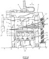
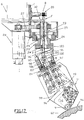
- FIGS. 1 to 4 there is shown schematically a contact winding-depositing machine according to the invention and more precisely a machine with four contact winding-depositing heads working in parallel.
- the machine comprises, in known manner, a gantry 1 carrying a first carriage 2 movable in a first horizontal direction X parallel to the longitudinal axis of the gantry 1, using appropriate on-board motor means 3.
- the carriage 2 carries a second carriage 4 movable in a second horizontal direction Y perpendicular to the direction X, using appropriate motor means 5 on board the carriage 4.
- the second carriage 4 carries a vertical beam 6 mounted vertically movable on the carriage 4 in a direction Z.
- a plate 7 head-winding-depositing contact in the form of a horizontal beam.
- the plate 7 carries four identical heads T1 to T4 (shown schematically only in Figures 1 and 2) arranged side by side in line, along the transverse axis of the gantry , that is to say in the Y direction, but the stage could just as easily carry a different number of heads, one, two or three, or even a number greater than four.
- All the heads T1 to T4 are mounted mobile in rotation on the plate-beam 7 around a vertical axis symbolized at 8.
- Each head T1 to T4 comprises a roller 9 for winding and depositing in contact with the horizontal axis.
- the heads T1 to T4 are capable of being brought opposite or in contact each with a mandrel symbolized at M in FIGS. 1 to 4, on which a part, for example a connecting rod made of composite material, must be produced.
- the mandrels M are placed in parallel to the horizontal in the direction X, between two dolls 10 of a multi-station turning bench 11, the mandrels M being presented to the bench and, after winding-removal in contact , removed, using a table 12 movable in height, carrying idler rollers 13 for supporting the mandrels M opposite each head T1 to T4 respectively.
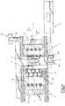
- each head T1 to T4 is supplied by six wires symbolized at F in FIGS. 1 to 4, coming, according to an essential characteristic of the invention, from coils B carried by a static creel C completely separate from the heads as well as from the gantry 1 and placed in one of the angles of the gantry (figure 4) so as to deliver all the wires F, that is to say twenty-four in total, along a sheet situated in a vertical plane parallel to the longitudinal axis (direction X) of said gantry 1, laterally to the latter.
- the wires F are arranged in space and guided, between the creel C and the heads T1 to T4, so as to sweep the minimum space during the movements of the heads and to reduce the jerks in the wire feed speed.
- the vertical ply of wires F is delivered by the creel C laterally to the space for changing the winding-depositing heads by being sent to a set of idler pulleys 14, identical, carried by a parallel horizontal axis. in the Y direction, fixed and arranged in the vicinity of the ground and the end, on the creel side, of the parts being wound-dropped in contact.
- the pulleys 14 return the wires F to an identical series of pulleys 15 carried by an axis parallel to that of the pulleys 14 and connected to the carriage 2 by means of a support 16.
- the pulleys 15 direct the wires F onto another series 17 of pulleys mounted on an axis parallel to that of the pulleys 15 and connected to the carriage 2 by a support 18.
- the pulleys 17 are divided into four sets, namely one per winding-depositing head at contact T1 to T4, of six pulleys with different diameters in cascade, responsible for bringing the wires substantially at the level (in the direction X) of the heads T1 to T4.
- the wires F then pass from the pulleys 17 to another series of four sets of pulleys 19 responsible for directing the wires towards the horizontal beam 7 head holder.
- the pulleys 19 have in each set different diameters in cascade, are arranged along axes orthogonal to the axis of the pulleys 17 and offset both in height and laterally.
- the pulleys 19 are arranged in height as close as possible to the beam 7 while remaining at a height sufficient to pass over the head of the operators of the machine.
- the wires F are received on the beam 7 on identical pulleys 20 placed on an axis parallel to that from pulleys 19 and therefore in the direction X, perpendicular to the four heads T1 to T4.
- a command / control console for the machine suspended from a beam 22 secured to the gantry 1, at one of its angles (FIG. 4).
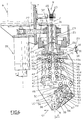
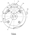
- the winding-depositing head in contact T shown in FIG. 5 is mounted so that it can rotate about a single vertical axis 8 on the plate-beam 7, by means of a rotating part 23 at the bottom of which is fixed a circular flange 24 on which is mounted the head T.
- the rotating part 23 has a central well 25 coaxial with the axis 8 for the passage of the wires F and is pivotally mounted on an annular support assembly 26 attached laterally to the plate-beam 7.
- the piece 23 is driven in rotation by means of a toothed belt 27 driven by an electric motor 28 also integral with the beam 7, a single motor 28 driving by the same belt 27 the different winding heads - removal T1 to T4 (figure 5) of the machine.
- the flange 24 is also pierced with a central hole 33 coaxial with the well 25, for the passage of the wires F.
- FIG. 8 On the underside of the flange 24, laterally to the hole 33 (FIGS. 8 and 10), is attached (FIG. 8) a vertical support 35 carrying a displacement cylinder 36, vertically, via a connecting piece 37, of a plate -support 38, slightly offset relative to the axis 8 and to the hole 33.
- the support plate 38 carries, on the side opposite to the jack 36, the means of feeding-guiding the wires F to the caster 9 of winding-depositing in contact and the various other means of pushing, cutting, retaining the threads, which we will now describe in more detail and which, for the sake of clarity, are not represented in FIGS. 8 and 10, but only in FIGS. 6, 7, 9 to 12.
- the plate 38 is guided vertically by appropriate means along the fixed part 35 and carries, below and on either side of the well formed by the hole 33, two series 39 and 40 facing pulleys 39a, 39b, 39c; 40a, 40b, 40c ( Figures 6 and 7) mounted on a non-return wire freewheel and each cooperating with an idler roller 39d, 40d provided with an O-ring pressing the wire at the bottom of the groove of the associated pulley at the end of wire contact area on said pulley.
- the pulleys 39a, 39b, 39c; 40a, 40b, 40c are mounted on oscillating levers 41 for clearance purposes for the placement of the wires.
- the wires of the pulley set 39 are directed (FIG. 6), via deflection pulleys 42, 43, on a set 44 of three twin grooved rollers, while the wires of the pulley set 40 are directed, via pulleys of reference 45, on a set 46 of three other twin grooved casters.
- a square lever 34a carrying at one end ( Figure 6) a roller 39d, 40d whose other end ( Figure 9) is biased by a spring 34b for adjusting the pressure of said roller.
- the sets of rollers 44,46 are responsible, in the known manner, for presenting the wires in two plies F1 and F2 of three wires side by side, directed tangentially to the roller 9 for winding-depositing on contact.
- a thread pushing device comprising, for each ply F1, F2, a drive roller 48 mounted on a free wheel 49 (FIGS. 6 and 7) and driven by a toothed belt 50 also engaged with roulette 9.
- Each roller 48 cooperates with three opposing pressure rollers 51 for driving the three wires of the ply considered (F1, F2).
- the three rollers 51 of the same roller 48 are superimposed and controlled independently by three pneumatic cylinders 52 flat, superimposed, arranged (FIG. 9) on the face of the plate 38 opposite that on which the rollers 48, 51 are arranged.
- the jacks 52 selectively actuate the rollers 51 via a lever system 53 articulated around an axis 54 passing through the support plate 38.
- the three cutting devices of each set are arranged side by side opposite the corresponding wires and are constituted in the known manner by a cutting blade 55 (FIGS. 11,12) mounted at the end of an articulated lever 56.
- Figures 11 and 12 show three levers 56 each carrying a blade 55 and mounted, in accordance with the invention, oscillating on a common axis 57 passing through the support plate 38, the cutting members being on one side of the plate and the control means being arranged on the other side ( Figure 9).
- control means consist of three pneumatic cylinders 58, flat, superimposed, acting by suitable levers 59 on parts 60 (tubular or solid), coaxial with the axis 57 and superimposed, each controlling a lever 56.
- the rollers 48 are determined so as to have a peripheral speed slightly lower than that of the roller 9. This, combined with the mounting of the rollers 48 on a wheel free 49, is of particular interest in case of cutting a wire. Indeed, when a wire is cut by one of the devices (55), the two ends of this wire will move away from each other because the drive speed communicated by the wheel 9 is greater than that of the rollers 48. Thus, the downstream end will be put in place by the roller 9 without the upstream end, which is set back, being applied by the caster on the part to be coated. When the upstream end reaches the caster 9 it will be taken care of by the latter which will communicate an acceleration to it to restore it to its normal speed of travel.
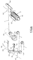
- the machine is provided with a device for compacting the wires in place 61 mounted at the level of the caster 9 and in the immediate vicinity thereof, such a device being shown in detail in the figures 13 to 15.
- the device comprises two rollers 62,63 mounted free in rotation on two axes 64,65 fixed at the end of two arms 66,67 rotatably mounted around two axes 68,69 which pass respectively in the middle of the contact zone of each caster with the surface to be coated and allow the orientation of each caster independently with respect to this surface.
- the rods 70 and 71 defining the axes 68, 69 are mounted free to rotate each on a bent piece 72 urged by a spring 73 anchored on a plate 74 for fixing the compacting device to the head T.
- Coil springs 75,76 threaded on the rods 70,71 are responsible for constantly returning the rollers 62,63 to their twin position (coaxial and side by side) shown in FIGS. 13 to 15.
- rollers 62, 63 remain in the paired position and this, whatever the distance, along the vertical Z, from the pair of rollers 62 , 63 opposite the removal head T.
- rollers 62, 63 When the rollers 62, 63 are located opposite different surface areas, as illustrated in 78 and 79 in FIG. 15, the rollers follow their respective sides by moving independently of each other, while remaining substantially in tangency at their lower edge 80, thanks to the permanent action of the springs 73 pressing the rollers against the surface, whatever the mutual inclination of the surface sections 78,79 and whatever (80 ') the distance, along the vertical axis Z, of the rollers 62,63 with respect to the removal head T, as shown in dashed lines in FIG. 15.
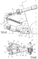
- FIG. 16 is an enlarged view of the device for delivering a wire from the creel C symbolized in FIG. 1.
- the creel C consists of a cabinet in which are housed coils B of wire in a number equal to that of the wires used or likely to be used by the machine.
- the coils B are arranged horizontally and mounted on a drum 81 driven in rotation by a pneumatic motor 82.
- the wire F passes on a wetting roller 83 then on a return roller 84 towards a servo device of the puppet type comprising a pulley 85 driven by an electric motor with variable speed drive 86, a puppet 87 and a potentiometer 88 including the axis of rotation is integral with the axis of rotation 89 of the dummy 87 and the midpoint of which controls the input of the variator of the motor 86.
- the puppet 87 comprises a roller 90 for controlling the pivoting arm 91 of the puppet, moved by the rod of a pneumatic jack 92, the arm 91 being resiliently returned by a spring 93.
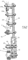
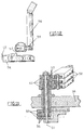
- FIGS. 17 to 20 illustrate an alternative embodiment of the or each head T 'of winding-depositing on contact, more particularly intended for depositing on contact on a surface having a significant slope, 45 ° for example, for example convex or concave , symbolized at 94.
- This surface 94 belongs to a part that can be driven in rotation or to a static part, that is to say not driven in rotation about a horizontal axis, this surface being able to be placed on a support allowing to modify the position in space, or presentation, of the part to be coated opposite the depositing head T '.
- the head T ' is identical to the head T of FIG. 6 with the only difference that it is mounted on the plate 7 head-mounted so as to pivot not only around the vertical axis 8, but also around a horizontal axis 95 perpendicular to axis 8 and to direction Y, as well as around an axis 96 intersecting the axes 8 and 95 and coaxial with the axis of movement of the winding caster 9 or deposited on the head T 'in the direction of the part to be coated.
- the head T ′ has a flange 24 similar to that of the head T of FIG. 6, fixed on a rotary crown 97 driven in rotation around the axis 96 by an electric motor 98 for example (FIGS. 18 to 20) by means of a toothed belt 99.
- the crown 97 and the motor 98 are carried by a first base 100 mounted articulated around the horizontal axis 95 under the action of an electric motor 101 and by means of a toothed belt 102.
- the base 100 and the motor 101 are carried by a second base 103 mounted to rotate around the axis 8 while being fixed to the rotating part 23.
- the base 103 is provided with a passage 104 for the wires F.
- the base 100 is arranged to allow the passage of the wires F in the direction of the head T ′ and comprises for this purpose (FIGS. 19, 20) a yoke 105 integral with the crown 97 and carrying pulleys 106 for guiding the wires.
- the crown 97 and the yoke 105 are of course provided with a central passage 107 for the wires.
- the pulleys 106 are arranged so as to ensure mutual offset in the space of the six wires F for good distribution in the direction of the two sets of pulleys 39 and 40 for taking charge wires on the head T '.
- the machine illustrated in Figures 1 to 4 is capable of both winding, the rollers 9 of the heads T1 to T4 being kept away from the parts to be wound (mandrels M) while these are rotated by the 10 dolls and removal on contact.
- the versatile nature (winding or depositing on contact) of the machine allows for easier and faster winding start because the wire is, at the start, glued to the piece to be wound by the winding head.
- the rotation of the winding head around the vertical axis 8 makes it possible to give the winding of the wire on the part M the desired inclination relative to the longitudinal axis of the part.
- the machine is also capable of carrying out on the parts M all of the deposit operations in contact with the wires F, automatically following the outline of the parts as they rotate.
- the displacement in Z of the depositing wheel 9 is essentially ensured by the beam 6 and the jack 36 carried by the depositing head is essentially responsible for ensuring a constant pressing pressure of said wheel on the part to be coated throughout from removal to contact.
- the automatic contour tracking with regulation of the contact pressure of the caster 9 is obtained from the analysis of the surface to be coated and computer processing of the desired trajectories (computer-aided design and manufacturing).
- the invention takes all its interest in the possibility thus offered of mounting several winding-depositing heads in contact on the same vertically movable support beam (Z), working in parallel and simultaneously, so that at the same time produces several identical parts, four in the example given here, but may be less or more. This correspondingly reduces the production costs of said parts, which it is also certain that they have the same characteristics of winding-depositing on contact.
- the particular arrangement of the means of routing the wires F between the creel C and the winding-depositing heads in contact allows free movement around the machine under the gantry 1, reduces the importance sweeping the wires during X, Y movements of the winding-depositing heads on contact.
- the wires F sweep a vertical fan surface of substantially reduced angle.
- the installation of the sets of pulleys 14 and 15 makes it possible to reduce the jolts of the wire feed speed. Indeed, in the absence of the set of pulleys 14 which forms a flywheel of wires, between the creel C and the carriage 2, the traction on the wires when moving the winding-depositing heads T1 to T4 to go from the end of the pieces M creel side C at the other end, would be stronger and of a significantly greater amplitude. Such a reduction in unwinding of the wire feed speed is particularly sensitive and advantageous at high winding speed because it spares the wires as much.
- the grid 32 prevents any tangling of the wires F, regardless of the distance of the caster 9 from the part 24.
- the pulley device with freewheel and pinch rollers (39,40; 39d, 40d) prevents the reversal of each thread and therefore keeps it in tension (upstream side), at each cut of the thread by the cutting device (55 ).
- the device with freewheel drive rollers and pressure rollers allows the two ends of the cut wire to be dissociated, avoiding the sticking of the upstream end by the roller 9 when it is placed in contact or at the end of winding. and ensures the appropriate pushing of the different wires in the direction of said roller 9.
- the compacting device (62 to 76) ensures a regular and perfect bonding of the wires on the coated surface by matching the changes in inclination of the surface thanks to the rollers 62,63 constrained by the springs 73 to be pressed constantly and automatically against the running surface.
- the means 81 to 92 for controlling the delivery of each thread F allow the machine to cope with variations in thread tension resulting from the method of placing the threads.
- Said means 81 to 92 ensure the braking of the wire during winding to allow the unwinding of the wire under a high tension, the latter being necessary to detach the wire loaded with resin from the reel.
- the jack 92 is supplied with compressed air under an adjustable pressure. It comes to press the roller 90 on the arm 91 of the puppet, forcing it to come to the left while considering FIG. 16.
- the potentiometer 88 then gives the order to the motor 86 to brake and no longer to pull, until the torque due to the tension of the wire balances the torque exerted by the jack 92 on the jack 87.
- the thread tension is adjusted by adjusting the air pressure in the cylinder 92.
- the head T 'in FIG. 17 is more specifically intended for removal on contact, but can just as well carry out a winding.
Abstract
Description
La présente invention a trait à la réalisation de structures en matériau composite et plus précisément de pièces de forme plus ou moins complexe, constituées par la superposition sur un support approprié de couches de fibres continues pré-imprégnées mises en place par bobinage et/ou dépose au contact.The present invention relates to the production of structures in composite material and more precisely of parts of more or less complex shape, constituted by the superposition on a suitable support of layers of continuous prepreg fibers put in place by winding and / or removal in touch with.
L'invention vise la réalisation d'une machine polyvalente capable aussi bien de bobiner ou enrouler que de déposer au contact plusieurs fils simultanément sur un même support et plus précisément encore un nombre important de fils.The invention relates to the production of a versatile machine capable of winding or winding as well as depositing several wires in contact simultaneously on the same support and more precisely still a large number of wires.
Par fil on entend dans la présente description un groupe de fibres continues, agglomérées, en forme de ruban ou bande, stocké sur une bobine.By yarn is meant in the present description a group of continuous fibers, agglomerated, in the form of a ribbon or strip, stored on a spool.
On connaît déjà diverses machines capables d'effectuer un bobinage ou une dépose au contact de plusieurs fils pré-imprégnés en même temps.Various machines are already known which are capable of winding or depositing in contact with several prepreg wires at the same time.
Le document EP-0.361.828 décrit une machine de dépose au contact de plusieurs fils disposés en une nappe et appliqués par une tête mobile suivant plusieurs axes, supportée par un portique et agencée en sorte de déposer les fils sur un corps en rotation autour d'un axe horizontal.Document EP-0.361.828 describes a machine for depositing in contact with several wires arranged in a sheet and applied by a head movable along several axes, supported by a gantry and arranged so as to deposit the wires on a body rotating around 'a horizontal axis.
Les fils sont déroulés à partir de bobines embarquées sur l'équipage mobile porte-tête.The wires are unwound from coils on board the head-holder mobile equipment.
Un tel agencement se traduit par un encombrement et un poids important de l'équipage mobile portant les bobines, limitant substantiellement le nombre de fils distincts à déposer et les capacités de mouvement dans l'espace de la tête de dépose.Such an arrangement results in a bulk and a significant weight of the mobile assembly carrying the coils, substantially limiting the number of separate wires to deposit and movement capabilities in the space of the removal head.
Suivant un autre inconvénient, si un problème survient sur l'une des bobines, une cassure de fil par exemple, l'accessibilité à la bobine pour dépannage est problématique et délicate notamment si la pièce en cours de revêtement est importante.According to another drawback, if a problem occurs on one of the coils, for example a wire break, accessibility to the coil for troubleshooting is problematic and delicate, especially if the part being coated is large.
Le document US-4.679.291 a trait à un même type de machine portique pour la dépose au contact de fibres sur la paroi d'un moule fixe. Cette machine présente les mêmes inconvénients, encore plus accentués pour ce qui concerne les capacités de mouvement et positionnement de la tête de dépose et l'accessibilité aux bobines de fils, du fait que la pièce à revêtir est immobile et de dimensions très importantes.The document US Pat. No. 4,679,291 relates to the same type of gantry machine for depositing in contact with fibers on the wall of a fixed mold. This machine has the same drawbacks, which are even more accentuated with regard to the movement and positioning capacities of the deposition head and the accessibility to the spools of thread, because the part to be coated is immobile and of very large dimensions.
Par le document US-4.699.683 on connaît également une machine portique pour la dépose au contact simultanée de plusieurs fils sur une pièce, à l'aide d'un organe applicateur porté par une tête de dépose multi-axes agencée de manière à supporter elle-même les bobines de fil.Document US-4,699,683 also discloses a gantry machine for depositing several wires simultaneously on a workpiece, using an applicator member carried by a multi-axis depositing head arranged so as to support itself the spools of thread.
Un tel agencement des bobines alourdit considérablement la tête de dépose, amoindrit substantiellement sa manoeuvrabilité et sa capacité de positionnement dans l'espace. Il est à noter à ce propos que la mobilité de la tête de dépose est possible suivant les trois directions cartésiennes X, Y et Z et seulement deux axes de rotation, d'une part vertical et, d'autre part horizontal et orthogonal à l'axe de l'organe applicateur des fils, ce qui limite les possibilités de placement de la tête qui ne peut donc pivoter autour d'un axe parallèle à celui dudit organe applicateur.Such an arrangement of the coils considerably increases the depositing head, substantially reduces its maneuverability and its positioning capacity in space. It should be noted in this connection that the mobility of the deposition head is possible in the three Cartesian directions X, Y and Z and only two axes of rotation, on the one hand vertical and, on the other hand horizontal and orthogonal to l 'axis of the wire applicator member, which limits the possibilities of placing the head which cannot therefore pivot about an axis parallel to that of said applicator member.
L'invention vise à remédier à ces problèmes et inconvénients en proposant une machine capable d'effectuer indifféremment un bobinage sur une pièce en rotation autour d'un axe ou une dépose au contact sur une pièce fixe ou mobile, de plusieurs fils simultanément à l'aide d'une tête à la fois maniable et légère.The invention aims to remedy these problems and drawbacks by proposing a machine capable of carrying out either a winding on a part rotating around an axis or a deposit in contact on a fixed or mobile part, of several wires simultaneously to the with a handy and light head.
A cet effet, l'invention a pour objet une machine pour le bobinage-dépose au contact simultané d'une pluralité de fils individuels, comprenant :
- un portique supportant une platine porte-tête de bobinage-dépose au contact, mobile dans les trois directions de repérage cartésien,
- au moins une tête de bobinage-dépose au contact montée mobile en rotation sur la platine autour d'au moins un axe vertical et comportant une roulette de bobinage-dépose au contact mobile sur la tête en direction du support à revêtir, des moyens de présentation sur ladite roulette des fils suivant au moins deux nappes tangentes, des moyens sélectifs d'entraînement et de coupe de chaque fil, et
- une pluralité de bobines délivrant lesdits fils,
caractérisée en ce que lesdites bobines sont montées sur un cantre fixe et les fils sont guidés entre le cantre et la tête de bobinage-dépose au contact par des jeux de poulies de renvoi agencées en sorte de limiter la surface balayée par les fils et de réduire les à-coups de la vitesse de dévidage des fils.To this end, the subject of the invention is a machine for winding and depositing in simultaneous contact with a plurality of individual wires, comprising:
- a gantry supporting a head-winding-depositing plate on contact, movable in the three Cartesian locating directions,
- at least one winding-depositing head in contact mounted movable in rotation on the plate about at least one vertical axis and comprising a winding-depositing wheel in moving contact on the head in the direction of the support to be coated, presentation means on said wheel of the wires following at least two tangent layers, selective means for driving and cutting each wire, and
- a plurality of coils delivering said wires,
characterized in that said coils are mounted on a fixed creel and the wires are guided between the creel and the winding-depositing head in contact by sets of deflection pulleys arranged so as to limit the surface swept by the wires and to reduce the jerks of the wire feed speed.
Suivant une application de l'invention au bobinage-dépose au contact de pièces allongées entraînées en rotation autour de leur axe, la machine comporte plusieurs têtes montées en parallèle sur la platine, alimentées en fils par le même cantre et aptes à revêtir par bobinage ou dépose au contact simultanément autant de pièces, disposées en parallèle sur un même banc assurant la rotation de chaque pièce en synchronisme avec la machine.According to an application of the invention to winding-depositing in contact with elongated parts driven in rotation about their axis, the machine comprises several heads mounted in parallel on the plate, supplied with wires by the same creel and suitable for coating by winding or simultaneously deposits as many pieces, placed in parallel on the same bench ensuring the rotation of each piece in synchronism with the machine.
Suivant une autre caractéristique, chaque tête de bobinage-dépose au contact comporte :
- une bride circulaire munie d'un passage central pour les fils et fixée à une pièce montée sur ladite platine, entraînée en rotation autour dudit axe vertical et munie d'un passage central pour les fils,
- un support monté sur la bride en sorte de se déplacer en translation suivant un axe confondu avec l'axe de rotation de la tête, ledit support portant ladite roulette de bobinage-dépose au contact et lesdits moyens d'entraînement et coupe des fils ainsi que des jeux de poulies de guidage des fils et anti-retour,
- lesdits fils étant amenés en étant regroupés en un faisceau parallèle sensiblement dans l'axe desdites bride et pièce rotative et guidés à l'aide d'une grille guide-fil montée libre en rotation dans ledit passage central de ladite pièce rotative.
- a circular flange provided with a central passage for the wires and fixed to a part mounted on said plate, driven in rotation about said vertical axis and provided with a central passage for the wires,
- a support mounted on the flange so as to move in translation along an axis coincident with the axis of rotation of the head, said support carrying said winding-depositing wheel in contact and said drive means and cutting wires as well as sets of pulleys for guiding the wires and non-return,
- said wires being brought together by being grouped in a parallel bundle substantially in the axis of said flange and rotating part and guided by means of a wire guide grid mounted to rotate freely in said central passage of said rotating part.
Suivant encore une autre caractéristique de la machine, chaque fil de chaque tête de bobinage-dépose au contact comporte un dispositif d'entraînement comprenant un galet monté sur une roue libre entraînée en même temps que la roulette de bobinage-dépose au contact mais avec une vitesse légèrement inférieure à celle de ladite roulette, un galet presseur d'application ou non du fil contre le galet entraîneur et un dispositif anti-retour de fil en cas de coupe d'un fil.According to yet another characteristic of the machine, each wire of each contact winding-depositing head comprises a drive device comprising a roller mounted on a free wheel driven at the same time as the contact winding-depositing roller but with a speed slightly lower than that of said roller, a pressure roller applying or not the wire against the driving roller and a wire non-return device in the event of a wire being cut.
Suivant encore une autre caractéristique de la machine, chaque tête de bobinage-dépose au contact comporte un dispositif de compactage des fils plaqués sur la pièce à revêtir, disposé à proximité immédiate de la roulette de dépose et constitué de deux roulettes indépendantes, libres en rotation autour de deux axes qui passent respectivement au milieu de la zone de contact de chaque roulette avec la surface à revêtir et permettent l'orientation de chaque roulette indépendamment par rapport à cette surface, des moyens étant prévus pour plaquer en permanence lesdites roulettes contre la surface à recouvrir.According to yet another characteristic of the machine, each winding-depositing head in contact comprises a device for compacting the wires plated on the part to be coated, disposed in the immediate vicinity of the depositing wheel and consisting of two independent rollers, free to rotate around two axes which pass respectively in the middle of the contact zone of each roller with the surface to be coated and allow the orientation of each roller independently with respect to this surface, means being provided for permanently pressing said rollers against the surface to cover.
Suivant une application de l'invention à la dépose au contact de pièces statiques, la tête de bobinage-dépose au contact est pourvue de deux autres axes de rotation.According to an application of the invention to the removal in contact with static parts, the winding-removal head in contact is provided with two other axes of rotation.
A cet effet, suivant un mode de réalisation, ladite bride de chaque tête de bobinage-dépose au contact est montée rotative sur une première embase, elle-même montée rotative sur une seconde embase, montée rotative sur ladite platine autour dudit axe vertical, l'axe de rotation de la première embase étant perpendiculaire à la fois à l'axe de rotation de ladite bride et à l'axe de rotation de ladite seconde embase.To this end, according to one embodiment, said flange of each winding-depositing head in contact is rotatably mounted on a first base, itself rotatably mounted on a second base, rotatably mounted on said plate around said vertical axis, l the axis of rotation of the first base being perpendicular both to the axis of rotation of said flange and to the axis of rotation of said second base.
Suivant encore un autre caractéristique de la machine, le cantre est muni, pour chaque fil, d'un dispositif de délivrance-freinage-annulation de tension de dévidage comprenant un moteur pneumatique d'entraînement en rotation de la bobine de fil et un dispositif d'asservissement du type pantin constitué d'un moto-variateur électrique entraînant une poulie de tirage du fil, d'un pantin, d'un potentiomètre dont l'axe de rotation est solidaire de l'axe de rotation du pantin et dont le point milieu commande l'entrée du variateur dudit moto-variateur et d'un moyen de contrôle du bras dudit pantin, en vue de permettre le dévidage du fil avec des tensions appropriées au bobinage et à la dépose au contact.According to yet another characteristic of the machine, the creel is provided, for each wire, with a device for delivering-braking-canceling unwinding tension comprising a pneumatic motor for rotating the spool of wire and a device for control of the puppet type consisting of an electric motor-variator driving a wire pulling pulley, a puppet, a potentiometer including the axis of rotation is integral with the axis of rotation of the puppet and the midpoint of which controls the input of the variator of said motor-variator and of a means of controlling the arm of said puppet, in order to allow the unwinding of the wire with voltages suitable for winding and removal on contact.
D'autres caractéristiques et avantages ressortiront de la description qui va suivre d'un mode de réalisation d'une machine selon l'invention, description donnée à titre d'exemple uniquement et en regard des dessins annexés sur lesquels :
- Figure 1 est une vue schématique en élévation latérale d'une machine selon l'invention ;
- Figure 2 est une vue de gauche de la machine de la figure 1 ;
- Figure 3 représente la machine de la figure 1 vue de l'autre côté ;
- Figure 4 est une vue de dessus de la machine de la figure 1 ;
- Figure 5 est une vue de dessus de l'ensemble des têtes de bobinage-dépose au contact de la machine ;
- Figure 6 est une vue en élévation latérale d'une tête de bobinage-dépose au contact ;
- Figure 7 est une vue en coupe suivant la ligne A-A du dispositif de la figure 6 montrant uniquement et partiellement les organes représentés sur cette figure 6 ;
- Figure 8 est une vue en coupe suivant la même ligne A-A du dispositif de la figure 6, montrant les organes servant à assurer une pression constante de la roulette de dépose ;
- Figure 9 est une vue de la tête de bobinage-dépose de la figure 6 montrant la face de la tête opposée à celle de la figure 6 ;
- Figure 10 est une vue partielle de dessus de la tête de bobinage-dépose de la figure 6 montrant l'arrivée des fils et la disposition latérale de la plaque-support de la tête ;
- Figure 11 est une vue partielle en coupe suivant la ligne B-B de la figure 9, des moyens d'actionnement des dispositifs de coupe des fils ;
- Figure 12 est une vue en éclaté d'un dispositif de coupe de fil ;
- Figure 13 est une vue en élévation latérale d'un dispositif de compactage associé à la tête de bobinage-dépose au contact ;
- Figure 14 est une vue de dessus du dispositif de compactage de la figure 13 ;
- Figure 15 est une vue de droite du dispositif de compactage de la figure 13 ;
- Figure 16 est une vue schématique en perspective des moyens de dévidage-freinage et réduction de tension d'un fil du cantre selon l'invention ;
- Figure 17 représente une variante de réalisation d'une tête de dépose au contact à trois axes de rotation concourants ;
- Figure 18 est une vue agrandie de la structure de montage interposée entre la tête de la figure 17 et la poutre porte-tête mobile en Z ;
- Figure 19 est une vue en coupe suivant la ligne C-C du dispositif de la figure 18, et
- Figure 20 est une vue en coupe suivant la ligne D-D du dispositif de la figure 19.
- Figure 1 is a schematic side elevational view of a machine according to the invention;
- Figure 2 is a left view of the machine of Figure 1;
- Figure 3 shows the machine of Figure 1 seen from the other side;
- Figure 4 is a top view of the machine of Figure 1;
- Figure 5 is a top view of all the winding-depositing heads in contact with the machine;
- Figure 6 is a side elevational view of a winding-depositing head in contact;
- Figure 7 is a sectional view along line AA of the device of Figure 6 showing only and partially the organs shown in this Figure 6;
- Figure 8 is a sectional view along the same line AA of the device of Figure 6, showing the members for ensuring a constant pressure of the depositing wheel;
- Figure 9 is a view of the winding-removal head of Figure 6 showing the face of the head opposite to that of Figure 6;
- Figure 10 is a partial top view of the winding-removal head of Figure 6 showing the arrival of the son and the lateral arrangement of the head support plate;
- Figure 11 is a partial sectional view along line BB of Figure 9, actuating means of the wire cutting devices;
- Figure 12 is an exploded view of a wire cutter;
- Figure 13 is a side elevational view of a compacting device associated with the winding-depositing head in contact;
- Figure 14 is a top view of the compacting device of Figure 13;
- Figure 15 is a right view of the compacting device of Figure 13;
- Figure 16 is a schematic perspective view of the unwinding-braking and tension reduction means of a creel wire according to the invention;
- Figure 17 shows an alternative embodiment of a deposition head in contact with three concurrent axes of rotation;
- Figure 18 is an enlarged view of the mounting structure interposed between the head of Figure 17 and the movable head beam in Z;
- Figure 19 is a sectional view along line CC of the device of Figure 18, and
- Figure 20 is a sectional view along line DD of the device of Figure 19.
Sur les figures 1 à 4 on a représenté schématiquement une machine de bobinage-dépose au contact selon l'invention et plus précisément une machine à quatre têtes de bobinage-dépose au contact travaillant en parallèle.In FIGS. 1 to 4 there is shown schematically a contact winding-depositing machine according to the invention and more precisely a machine with four contact winding-depositing heads working in parallel.
La machine comprend, à la manière connue, un portique 1 portant un premier chariot 2 mobile suivant une première direction horizontale X parallèle à l'axe longitudinal du portique 1, à l'aide de moyens moteurs embarqués 3 appropriés.The machine comprises, in known manner, a
Le chariot 2 porte un second chariot 4 mobile suivant une seconde direction horizontale Y perpendiculaire à la direction X, à l'aide de moyens moteurs appropriés 5 embarqués sur le chariot 4.The
Le second chariot 4 porte une poutre verticale 6 montée mobile verticalement sur le chariot 4 suivant une direction Z.The
A l'extrémité inférieure de la poutre 6 est fixée une platine 7 porte-tête de bobinage-dépose au contact, en forme de poutre horizontale.At the lower end of the
Dans le mode de réalisation représenté sur les figures 1 à 4, la platine 7 porte quatre têtes identiques T1 à T4 (représentées schématiquement uniquement sur les figures 1 et 2) disposées côte-à-côte en ligne, suivant l'axe transversal du portique, c'est-à-dire suivant la direction Y, mais la platine pourrait tout aussi bien porter un nombre différent de têtes, un, deux ou trois, ou même un nombre supérieur à quatre.In the embodiment shown in Figures 1 to 4, the
Toutes les têtes T1 à T4 sont montées mobiles en rotation sur la poutre-platine 7 autour d'un axe vertical symbolisé en 8. Chaque tête T1 à T4 comporte une roulette 9 de bobinage-dépose au contact d'axe horizontal.All the heads T1 to T4 are mounted mobile in rotation on the plate-
Les têtes T1 à T4 sont susceptibles d'être amenées en regard ou au contact chacune d'un mandrin symbolisé en M sur les figures 1 à 4, sur lequel doit être réalisée une pièce, par exemple une bielle en matériau composite.The heads T1 to T4 are capable of being brought opposite or in contact each with a mandrel symbolized at M in FIGS. 1 to 4, on which a part, for example a connecting rod made of composite material, must be produced.
A cet effet, les mandrins M sont placés en parallèle à l'horizontale suivant la direction X, entre deux poupées 10 d'un banc de tournage multi-poste 11, les mandrins M étant présentés au banc et, après bobinage-dépose au contact, enlevés, à l'aide d'une table 12 mobile en hauteur, portant des rouleaux fous 13 de support des mandrins M en regard respectivement de chaque tête T1 à T4.For this purpose, the mandrels M are placed in parallel to the horizontal in the direction X, between two
Comme on le verra plus en détail ci-après, chaque tête T1 à T4 est alimentée par six fils symbolisés en F sur les figures 1 à 4, provenant, selon une caractéristique essentielle de l'invention, de bobines B portées par un cantre statique C totalement distinct des têtes ainsi que du portique 1 et placé dans l'un des angles du portique (figure 4) en sorte de délivrer tous les fils F, soit vingt-quatre au total, suivant une nappe située dans un plan vertical parallèle à l'axe longitudinal (direction X) dudit portique 1, latéralement à ce dernier. Par souci de clarté, on n'a représenté sur les figures 1 et 2 que quatre fils F par tête de bobinage-dépose au contact T1 à T4 et le cantre C est symbolisé par un rectangle à l'intérieur duquel est représenté, en vue agrandie, le dispositif D de dévidage-freinage-régulation de tension d'un fil F. Bien entendu à chaque fil F délivré par le cantre correspond dans celui-ci un dispositif D identique à celui représenté sur la figure 1, un tel dispositif étant par ailleurs décrit plus loin.As will be seen in more detail below, each head T1 to T4 is supplied by six wires symbolized at F in FIGS. 1 to 4, coming, according to an essential characteristic of the invention, from coils B carried by a static creel C completely separate from the heads as well as from the
Suivant un autre aspect de l'invention, les fils F sont disposés dans l'espace et guidés, entre le cantre C et les têtes T1 à T4, de manière à balayer le minimum d'espace lors des déplacements des têtes et à réduire les à-coups de la vitesse de dévidage des fils.According to another aspect of the invention, the wires F are arranged in space and guided, between the creel C and the heads T1 to T4, so as to sweep the minimum space during the movements of the heads and to reduce the jerks in the wire feed speed.
A cet effet, la nappe verticale de fils F est délivrée par le cantre C latéralement à l'espace d'évolution des têtes de bobinage-dépose en étant envoyée sur un jeu de poulies de renvoi 14, identiques, portées par un axe horizontal parallèle à la direction Y, fixe et disposé au voisinage du sol et de l'extrémité, côté cantre C, des pièces en cours de bobinage-dépose au contact.To this end, the vertical ply of wires F is delivered by the creel C laterally to the space for changing the winding-depositing heads by being sent to a set of
Les poulies 14 renvoient les fils F sur une série identique de poulies 15 portées par un axe parallèle à celui des poulies 14 et reliées au chariot 2 par l'intermédiaire d'un support 16.The
Les poulies 15 dirigent les fils F sur une autre série 17 de poulies montées sur un axe parallèle à celui des poulies 15 et reliées au chariot 2 par un support 18.The
Les poulies 17 sont réparties en quatre jeux, à savoir un par tête de bobinage-dépose au contact T1 à T4, de six poulies à diamètres différents en cascade, chargées d'amener les fils sensiblement au niveau (dans la direction X) des têtes T1 à T4.The
Les fils F passent ensuite des poulies 17 à une autre série de quatre jeux de poulies 19 chargées de diriger les fils vers la poutre horizontale 7 porte-têtes.The wires F then pass from the
Les poulies 19 présentent dans chaque jeu des diamètres différents en cascade, sont disposées suivant des axes orthogonaux à l'axe des poulies 17 et décalées à la fois en hauteur et latéralement.The
Les poulies 19 sont disposées en hauteur le plus près possible de la poutre 7 en demeurant à hauteur suffisante pour passer au-dessus de la tête des opérateurs de la machine.The
Les fils F sont reçus sur la poutre 7 sur des poulies identiques 20 placées sur un axe parallèle à celui dès poulies 19 et donc à la direction X, à l'aplomb des quatre têtes T1 à T4.The wires F are received on the
Enfin, on a représenté en 21 (figures 2 et 4) une console de commande/contrôle de la machine, suspendue à une poutre 22 solidaire du portique 1, à l'un de ses angles (figure 4).Finally, there is shown at 21 (FIGS. 2 and 4) a command / control console for the machine, suspended from a
On va maintenant décrire selon un premier mode de réalisation, l'une des têtes de bobinage-dépose au contact de la machine en se reportant aux figures 5 à 12.We will now describe, according to a first embodiment, one of the winding-depositing heads in contact with the machine, referring to FIGS. 5 to 12.
La tête de bobinage-dépose au contact T représentée sur la figure 5 est montée mobile en rotation autour d'un seul axe vertical 8 sur la poutre-platine 7, par l'intermédiaire d'une pièce tournante 23 à la partie inférieure de laquelle est fixée une bride circulaire 24 sur laquelle est montée la tête T.The winding-depositing head in contact T shown in FIG. 5 is mounted so that it can rotate about a single
La pièce tournante 23 présente un puits central 25 coaxial à l'axe 8 pour le passage des fils F et est montée tourillonnante sur un ensemble support annulaire 26 rapporté latéralement à la poutre-platine 7.The
L'entraînement en rotation de la pièce 23 s'effectue à l'aide d'une courroie crantée 27 mue par un moteur électrique 28 également solidaire de la poutre 7, un seul moteur 28 entraînant par une même courroie 27 les différentes têtes de bobinage-dépose T1 à T4 (figure 5) de la machine.The
Au dessus du puits 25 de la pièce tournante 23 sont disposées lesdites poulies 20 renvoyant vers la tête T les fils F qui sont guidés dans ledit puits 25 par une grille en forme de disque circulaire 29 percé de six trous 30 pour les six fils F. Le disque 29, d'axe coaxial à l'axe 8, est monté mobile en rotation à l'extrémité inférieure d'une tige support 31 dont l'extrémité est fixée à une potence 32 solidaire de la poutre-platine 7.Above the well 25 of the
La bride 24 est également percée d'un trou central 33 coaxial au puits 25, pour le passage des fils F.The
Sur la face inférieure de la bride 24, latéralement au trou 33 (figures 8 et 10), est rapporté (figure 8) un support vertical 35 portant un vérin 36 de déplacement, verticalement, via une pièce de liaison 37, d'une plaque-support 38, légèrement déportée par rapport à l'axe 8 et au trou 33. La plaque-support 38 porte, du côté opposé au vérin 36, les moyens d'amenée-guidage des fils F à la roulette 9 de bobinage-dépose au contact et les divers autres moyens de poussage, coupe, retenue des fils, que l'on va maintenant décrire plus en détail et qui, par souci de clarté, ne sont pas représentés sur les figures 8 et 10, mais seulement sur les figures 6, 7, 9 à 12.On the underside of the
La plaque 38 est guidée verticalement par des moyens appropriés le long de la pièce fixe 35 et porte, en-dessous et de part et d'autre du puits formé par le trou 33 deux séries 39 et 40 en vis à vis de poulies 39a, 39b, 39c ; 40a, 40b, 40c (figures 6 et 7) montées sur roue libre anti-retour de fil et coopérant chacune avec un galet fou 39d, 40d pourvu d'un joint torique appuyant le fil en fond de gorge de la poulie associée en fin de zone de contact du fil sur ladite poulie. Les poulies 39a,39b,39c ; 40a,40b,40c sont montées sur des leviers oscillants 41 à des fins de dégagement pour la mise en place des fils.The
Les fils du jeu de poulies 39 sont dirigés (figure 6), via des poulies de renvoi 42,43, sur un jeu 44 de trois roulettes à gorge jumelées, cependant que les fils du jeu de poulies 40 sont dirigés, via des poulies de renvoi 45, sur un jeu 46 de trois autres roulettes à gorge jumelées.The wires of the pulley set 39 are directed (FIG. 6), via deflection pulleys 42, 43, on a
Sur l'axe des poulies 42,45 est articulé (figures 6 et 9) un levier en équerre 34a portant à une extrémité (figure 6) un galet 39d,40d dont l'autre extrémité (figure 9) est sollicitée par un ressort 34b de réglage de la pression dudit galet.On the axis of the
Les jeux de roulettes 44,46 sont chargés, à la manière connue, de présenter les fils en deux nappes F1 et F2 de trois fils côte à côte, dirigées tangentiellement à la roulette 9 de bobinage-dépose au contact.The sets of
Entre les roulettes 44,46 et la roulette 9 est disposé un sabot 47 en forme de coin sur les deux faces opposées duquel sont dirigées les deux nappes F1,F2.Between the
En amont du sabot 47 est prévu un dispositif de poussage des fils comprenant, pour chaque nappe F1,F2, un galet d'entraînement 48 monté sur une roue libre 49 (figures 6 et 7) et entraîné par une courroie crantée 50 en prise également avec la roulette 9.Upstream of the
Chaque galet 48 coopère avec trois galets presseurs antagonistes 51 d'entraînement des trois fils de la nappe considérée (F1,F2).Each
Les trois galets 51 d'un même galet 48 sont superposés et commandés indépendamment par trois vérins pneumatiques 52 plats, superposés, agencés (figure 9) sur la face de la plaque 38 opposée à celle sur laquelle sont disposés les galets 48,51.The three
Les vérins 52 actionnent sélectivement les galets 51 via un système de levier 53 articulé autour d'un axe 54 traversant la plaque support 38.The
Lorsqu'un galet 51 est amené par son vérin de commande 52 en contact avec le galet 48 associé, le fil correspondant est coincé et entraîné par ledit galet 48.When a
Par contre, lorsque ledit galet 51 est éloigné dudit galet 48, le fil n'est pas entraîné.On the other hand, when said
Sur les deux faces opposées du sabot sont disposés deux jeux de trois dispositifs de coupe de fil dont le principe est bien connu. Les trois dispositifs de coupe de chaque jeu sont disposés côte à côte en regard des fils correspondants et sont constitués à la manière connue d'une lame de coupe 55 (figures 11,12) montée à l'extrémité d'un levier articulé 56.On the two opposite faces of the shoe are arranged two sets of three wire cutting devices, the principle of which is well known. The three cutting devices of each set are arranged side by side opposite the corresponding wires and are constituted in the known manner by a cutting blade 55 (FIGS. 11,12) mounted at the end of an articulated
Sur les figures 11 et 12 on a représenté trois leviers 56 portant chacun une lame 55 et montés, conformément à l'invention, oscillant sur un axe commun 57 traversant la plaque support 38, les organes de coupe étant d'un côté de la plaque et les moyens de commande étant disposés de l'autre côté (figure 9).Figures 11 and 12 show three
Ces moyens de commande sont constitués de trois vérins pneumatiques 58, plats, superposés, agissant par des leviers appropriés 59 sur des pièces 60 (tubulaires ou pleines), coaxiales à l'axe 57 et superposées, commandant chacune un levier 56.These control means consist of three
Suivant une autre caractéristique de la tête de bobinage-dépose au contact selon l'invention, les galets 48 sont déterminés de façon à avoir une vitesse périphérique légèrement inférieure à celle de la roulette 9. Ceci, combiné au montage des galets 48 sur une roue libre 49, présente un intérêt particulier en cas de coupe d'un fil. En effet, lorsqu'un fil est coupé par l'un des dispositifs (55), les deux extrémités de ce fil vont s'éloigner l'une de l'autre du fait que la vitesse d'entraînement communiquée par la roulette 9 est supérieure à celle des galets 48. Ainsi, l'extrémité aval sera mise en place par la roulette 9 sans que l'extrémité amont, qui se trouve en retrait, soit appliquée par la roulette sur la pièce à revêtir. Lorsque l'extrémité amont atteint la roulette 9 elle sera prise en charge par cette dernière qui lui communiquera une accélération pour lui redonner sa vitesse normale de défilement.According to another characteristic of the contact winding-depositing head according to the invention, the
Ces mouvements différentiels sont permis par la roue libre 49.These differential movements are allowed by the
Sur les figures 6 et 9, on a représenté en 61 les six fils en nappe unique déposés au contact côte-à-côte par la roulette 9 sur une pièce (non représentée).In Figures 6 and 9, there is shown at 61 the six single ply son deposited in contact side by side by the
Suivant une autre caractéristique de l'invention, la machine est munie d'un dispositif de compactage des fils en place 61 monté à hauteur de la roulette 9 et à proximité immédiate de celle-ci, un tel dispositif étant représenté en détail sur les figures 13 à 15.According to another characteristic of the invention, the machine is provided with a device for compacting the wires in
Le dispositif comprend deux roulettes 62,63 montées libres en rotation sur deux axes 64,65 fixés à l'extrémité de deux bras 66,67 montés rotatifs autour de deux axes 68,69 qui passent respectivement au milieu de la zone de contact de chaque roulette avec la surface à revêtir et permettent l'orientation de chaque roulette indépendamment par rapport à cette surface.The device comprises two
Les tiges 70 et 71 définissant les axes 68,69 sont montées libres en rotation chacune sur une pièce coudée 72 sollicitée par un ressort 73 ancré sur une platine 74 de fixation du dispositif de compactage sur la tête T.The
Des ressorts hélicoïdaux 75,76 enfilés sur les tiges 70,71 sont chargés de rappeler constamment les roulettes 62,63 dans leur position jumelée (coaxiales et côte-à-côte) représentée sur les figures 13 à 15.Coil springs 75,76 threaded on the
En regard d'une surface plane comme illustré en 77 sur les figures 13 et 15, les roulettes 62,63 demeurent dans la position jumelée et, ce, quelle que soit l'éloignement, suivant la verticale Z, de la paire de roulettes 62,63 vis à vis de la tête de dépose T.Opposite a flat surface as illustrated at 77 in FIGS. 13 and 15, the
Lorsque les roulettes 62,63 se trouvent en regard de pans de surface différents, comme illustré en 78 et 79 sur la figure 15, les roulettes épousent leur pan respectif en se déplaçant indépendamment l'une de l'autre, tout en demeurant sensiblement en tangence au niveau de leur arête inférieure 80, et, ce, grâce à l'action permanente des ressorts 73 plaquant les roulettes contre la surface, quelle que soit l'inclinaison mutuelle des pans de surface 78,79 et quel que soit (80') l'éloignement, suivant l'axe vertical Z, des roulettes 62,63 vis à vis de la tête de dépose T, comme illustré en tiretés sur la figure 15.When the
La figure 16 est une vue agrandie du dispositif de délivrance d'un fil du cantre C symbolisé sur la figure 1.FIG. 16 is an enlarged view of the device for delivering a wire from the creel C symbolized in FIG. 1.
Le cantre C est constitué d'une armoire dans laquelle sont logées des bobines B de fil en nombre égal à celui des fils utilisés ou susceptibles d'être utilisés par la machine.The creel C consists of a cabinet in which are housed coils B of wire in a number equal to that of the wires used or likely to be used by the machine.
Les bobines B sont disposées horizontalement et montées sur un tambour 81 entraîné en rotation par un moteur pneumatique 82.The coils B are arranged horizontally and mounted on a
Le fil F passe sur un rouleau lécheur 83 puis sur un rouleau 84 de renvoi vers un dispositif d'asservissement du type pantin comprenant une poulie 85 mue par un moteur électrique à variateur de vitesse 86, un pantin 87 et un potentiomètre 88 dont l'axe de rotation est solidaire de l'axe de rotation 89 du pantin 87 et dont le point milieu commande l'entrée du variateur du moteur 86.The wire F passes on a wetting
Le pantin 87, dont le principe est bien connu, comporte un galet 90 de contrôle du bras pivotant 91 du pantin, mû par la tige d'un vérin pneumatique 92, le bras 91 étant rappelé élastiquement par un ressort 93.The
Les figures 17 à 20 illustrent une variante de réalisation de la ou chaque tête T' de bobinage-dépose au contact, plus particulièrement destinée à la dépose au contact sur une surface présentant une pente importante, 45° par exemple, par exemple convexe ou concave, symbolisée en 94. Cette surface 94 appartient à une pièce pouvant être entraînée en rotation ou à une pièce statique, c'est-à-dire non entraînée en rotation autour d'un axe horizontal, cette surface pouvant être placée sur un support permettant de modifier la position dans l'espace, ou présentation, de la pièce à revêtir en regard de la tête de dépose T'.FIGS. 17 to 20 illustrate an alternative embodiment of the or each head T 'of winding-depositing on contact, more particularly intended for depositing on contact on a surface having a significant slope, 45 ° for example, for example convex or concave , symbolized at 94. This
La tête T' est identique à la tête T de la figure 6 avec cette seule différence qu'elle est montée sur la platine 7 porte-têté en sorte de pivoter non seulement autour de l'axe vertical 8, mais également autour d'un axe horizontal 95 perpendiculaire à l'axe 8 et à la direction Y, ainsi qu'autour d'un axe 96 intersectant les axes 8 et 95 et coaxial à l'axe de déplacement de la roulette 9 de bobinage ou dépose sur la tête T' en direction de la pièce à revêtir.The head T 'is identical to the head T of FIG. 6 with the only difference that it is mounted on the
A cet effet, la tête T' comporte une bride 24 analogue à celle de la tête T de la figure 6, fixée sur une couronne rotative 97 entraînée en rotation autour de l'axe 96 par un moteur électrique 98 par exemple (figures 18 à 20) par l'intermédiaire d'une courroie crantée 99.To this end, the head T ′ has a
La couronne 97 et le moteur 98 sont portés par une première embase 100 montée articulée autour de l'axe horizontal 95 sous l'action d'un moteur électrique 101 et par l'intermédiaire d'une courroie crantée 102.The
L'embase 100 et le moteur 101 sont portés par une seconde embase 103 montée rotative autour de l'axe 8 en étant fixée à la pièce tournante 23.The
L'embase 103 est pourvue d'un passage 104 pour les fils F.The
L'embase 100 est agencée pour permettre le passage des fils F en direction de la tête T' et comporte à cet effet (figures 19, 20) une chape 105 solidaire de la couronne 97 et portant des poulies 106 de guidage des fils. La couronne 97 et la chape 105 sont bien entendu munies d'un passage central 107 pour les fils.The
Comme on peut le voir sur les figures 18 à 20, les poulies 106 sont disposées de façon à assurer le décalage mutuel dans l'espace des six fils F pour une bonne distribution en direction des deux jeux de poulies 39 et 40 de prise en charge des fils sur la tête T'.As can be seen in FIGS. 18 to 20, the
La machine illustrée par les figures 1 à 4 est capable de faire à la fois du bobinage, les roulettes 9 des têtes T1 à T4 étant maintenues à distance des pièces à bobiner (mandrins M) alors que celles-ci sont entraînées en rotation par les poupées 10 et de la dépose au contact.The machine illustrated in Figures 1 to 4 is capable of both winding, the
Bien entendu, tous les mouvements, déplacements, rotations et actionnements des divers organes mobiles ou actifs, au cours du processus de bobinage, sont programmés et gérés par ordinateur.Of course, all the movements, displacements, rotations and actuations of the various mobile or active members, during the winding process, are programmed and managed by computer.
Le caractère polyvalent (bobinage ou dépose au contact) de la machine permet un départ de bobinage plus facile et rapide car le fil est, au départ, collé sur la pièce à bobiner par la tête de bobinage.The versatile nature (winding or depositing on contact) of the machine allows for easier and faster winding start because the wire is, at the start, glued to the piece to be wound by the winding head.
La rotation de la tête de bobinage autour de l'axe vertical 8 permet de donner à l'enroulement du fil sur la pièce M l'inclinaison désirée par rapport à l'axe longitudinal de la pièce.The rotation of the winding head around the
La machine est également capable d'effectuer sur les pièces M toutes opérations de dépose au contact des fils F, en suivant automatiquement le contour des pièces au fur et à mesure de leur rotation. Le déplacement en Z de la roulette de dépose 9 est assuré essentiellement par la poutre 6 et le vérin 36 porté par la tête de dépose est chargé essentiellement d'assurer une pression d'appui constante de ladite roulette sur la pièce à revêtir tout au long de la dépose au contact. Le suivi automatique de contour avec régulation de la pression de contact de la roulette 9 est obtenu à partir de l'analyse de la surface à revêtir et traitement par ordinateur des trajectoires désirées (conception et fabrication assistées par ordinateur).The machine is also capable of carrying out on the parts M all of the deposit operations in contact with the wires F, automatically following the outline of the parts as they rotate. The displacement in Z of the
Même si la machine ne comporte qu'une tête T de bobinage-dépose au contact, le fait, conformément à l'invention, de placer à poste fixe le cantre C, permet d'alléger la tête, de la rendre plus manoeuvrable, d'accroître le nombre de fils pouvant être, simultanément sur une même tête, bobinés et/ou déposés au contact, ce nombre pouvant être supérieur à six. En outre, en cas de rupture ou de problème de fil au niveau du cantre C, l'accès et la remise en état sont bien plus aisés et rapides.Even if the machine only has a winding-depositing head T on contact, the fact, in accordance with the invention, of placing the creel C at a fixed post, makes it possible to lighten the head, to make it more maneuverable, d 'Increase the number of wires that can be, simultaneously on the same head, wound and / or deposited in contact, this number can be greater than six. In addition, in the event of a wire break or problem at canter C level, access and repair are much easier and faster.
Cependant, l'invention prend tout son intérêt dans la possibilité ainsi offerte de monter plusieurs têtes de bobinage-dépose au contact sur une même poutre-support mobile verticalement (Z), travaillant en parallèle et simultanément, en sorte que dans le même temps on réalise plusieurs pièces identiques, quatre dans l'exemple donné ici, mais pouvant être en nombre inférieur ou supérieur. Ceci diminue d'autant les coûts de production desdites pièces, dont on est sûr par ailleurs qu'elles ont les mêmes caractéristiques de bobinage-dépose au contact.However, the invention takes all its interest in the possibility thus offered of mounting several winding-depositing heads in contact on the same vertically movable support beam (Z), working in parallel and simultaneously, so that at the same time produces several identical parts, four in the example given here, but may be less or more. This correspondingly reduces the production costs of said parts, which it is also certain that they have the same characteristics of winding-depositing on contact.
Par ailleurs, l'agencement particulier des moyens d'acheminement des fils F entre le cantre C et les têtes de bobinage-dépose au contact, permet une libre circulation autour de la machine sous le portique 1, réduit l'importance du balayage des fils lors des déplacements en X,Y des têtes de bobinage-dépose au contact. C'est ainsi qu'entre les poulies fixes 14 et les poulies 15 mobiles en X, les fils F balaient une surface en éventail vertical d'angle substantiellement réduit.Furthermore, the particular arrangement of the means of routing the wires F between the creel C and the winding-depositing heads in contact, allows free movement around the machine under the
En outre, l'implantation des jeux de poulies 14 et 15 permet de réduire les à-coups de la vitesse de dévidage des fils. En effet, en l'absence du jeu de poulies 14 qui forme un volant de fils, entre le cantre C et le chariot 2, la traction sur les fils lors du déplacement des têtes de bobinage-dépose T1 à T4 pour aller de l'extrémité des pièces M côté cantre C à l'autre extrémité, serait plus forte et d'une amplitude sensiblement plus importante. Une telle réduction des à-coups de vitesse de dévidage est particulièrement sensible et intéressante à grande vitesse de bobinage car elle ménage d'autant les fils.In addition, the installation of the sets of
Au cours de la rotation des têtes autour de l'axe vertical 8, la grille 32 évite tout emmêlement des fils F, quel que soit l'éloignement de la roulette 9 vis à vis de la pièce 24.During the rotation of the heads around the
Le dispositif à poulies à roue libre et galets presseurs (39,40 ; 39d,40d) évite le retour en arrière de chaque fil et donc le maintient en tension (côte amont), à chaque coupure de fil par le dispositif de coupe (55).The pulley device with freewheel and pinch rollers (39,40; 39d, 40d) prevents the reversal of each thread and therefore keeps it in tension (upstream side), at each cut of the thread by the cutting device (55 ).
Le dispositif à galets d'entraînement à roue libre et galets presseurs (48, 51) permet la dissociation des deux extrémités du fil coupé, évitant le collage de l'extrémité amont par la roulette 9 à la dépose au contact ou en fin de bobinage et assure le poussage approprié des différents fils en direction de ladite roulette 9.The device with freewheel drive rollers and pressure rollers (48, 51) allows the two ends of the cut wire to be dissociated, avoiding the sticking of the upstream end by the
Le dispositif de compactage (62 à 76) assure un collage régulier et parfait des fils sur la surface revêtue en épousant les modifications d'inclinaison de la surface grâce aux roulettes 62,63 contraintes par les ressorts 73 de se plaquer constamment et automatiquement contre la surface de roulement.The compacting device (62 to 76) ensures a regular and perfect bonding of the wires on the coated surface by matching the changes in inclination of the surface thanks to the
Les moyens 81 à 92 d'asservissement de la délivrance de chaque fil F permettent à la machine de faire face aux variations de tension de fil résultant du mode de mise en place des fils.The means 81 to 92 for controlling the delivery of each thread F allow the machine to cope with variations in thread tension resulting from the method of placing the threads.
La dépose au contact nécessite en effet des tensions de fil de l'ordre de 1,5 N, alors que le bobinage implique des tensions de fil allant jusqu'à 100 N.Contact removal requires wire tensions of the order of 1.5 N, while winding involves wire tensions of up to 100 N.
Ces moyens permettent ainsi d'annuler la traction sur le fil pour faciliter le collage du fil sur la pièce au départ d'un bobinage ou d'une dépose au contact. En effet, dans ce cas, la tige du vérin 92 est escamotée et le bras 91 du pantin 87 prend une position vers la droite en considérant la figure 16, où le couple dû au ressort de rappel 93 est égal à celui dû à la traction du fil. Dans cette position, le moteur 86 tire sur le fil afin de presqu'annuler la tension due au moteur pneumatique 82 associé à la bobine B.These means thus make it possible to cancel the traction on the wire to facilitate the bonding of the wire on the part from a winding or a removal on contact. Indeed, in this case, the rod of the
Lesdits moyens 81 à 92 assurent le freinage du fil lors du bobinage pour permettre le dévidage du fil sous une tension importante, celle-ci étant nécessaire pour décoller de la bobine le fil chargé de résine.Said means 81 to 92 ensure the braking of the wire during winding to allow the unwinding of the wire under a high tension, the latter being necessary to detach the wire loaded with resin from the reel.
Pour ce faire, le vérin 92 est alimenté en air comprimé sous une pression réglable. Il vient appuyer le galet 90 sur le bras 91 du pantin, le forçant à venir sur la gauche en considérant la figure 16. Le potentiomètre 88 donne alors l'ordre au moteur 86 de freiner et non plus de tirer, jusqu'à ce que le couple dû à la tension du fil équilibre le couple exercé par le vérin 92 sur le pantin 87.To do this, the
Le réglage de la tension du fil se fait en réglant la pression de l'air dans le vérin 92.The thread tension is adjusted by adjusting the air pressure in the
La tête T' de la figure 17 est plus spécialement destinée à une dépose au contact, mais peut tout aussi bien effectuer un bobinage. Plusieurs têtes T' peuvent être agencées en parallèle sur une même poutre-platine 7, à la manière des têtes T1 à T4 de la machine des figures 1 à 4.The head T 'in FIG. 17 is more specifically intended for removal on contact, but can just as well carry out a winding. Several heads T 'can be arranged in parallel on the same plate-
Enfin, l'invention n'est évidemment pas limitée aux modes de réalisation décrits ci-dessus mais en couvre au contraire toutes les variantes.Finally, the invention is obviously not limited to the embodiments described above but on the contrary covers all the variants thereof.
Claims (9)
Applications Claiming Priority (2)
| Application Number | Priority Date | Filing Date | Title |
|---|---|---|---|
| FR9306613A FR2705655B1 (en) | 1993-05-26 | 1993-05-26 | Machine for winding-deposited in simultaneous contact with a plurality of individual wires. |
| FR9306613 | 1993-05-26 |
Publications (2)
| Publication Number | Publication Date |
|---|---|
| EP0626252A1 true EP0626252A1 (en) | 1994-11-30 |
| EP0626252B1 EP0626252B1 (en) | 1999-03-03 |
Family
ID=9447692
Family Applications (1)
| Application Number | Title | Priority Date | Filing Date |
|---|---|---|---|
| EP94450003A Expired - Lifetime EP0626252B1 (en) | 1993-05-26 | 1994-05-24 | Machine for contact winding a plurality of individual yarns simultaneously |
Country Status (8)
| Country | Link |
|---|---|
| US (1) | US5645677A (en) |
| EP (1) | EP0626252B1 (en) |
| JP (1) | JPH072428A (en) |
| AT (1) | ATE177051T1 (en) |
| CA (1) | CA2124311C (en) |
| DE (1) | DE69416718T2 (en) |
| ES (1) | ES2131179T3 (en) |
| FR (1) | FR2705655B1 (en) |
Cited By (14)
| Publication number | Priority date | Publication date | Assignee | Title |
|---|---|---|---|---|
| WO2006092514A2 (en) | 2005-03-03 | 2006-09-08 | Coriolis Composites | Fiber application machine |
| EP1785261A1 (en) * | 2005-11-09 | 2007-05-16 | The Boeing Company | Multihead composite material application machine programming method and apparatus |
| WO2008046878A1 (en) * | 2006-10-20 | 2008-04-24 | Astrium Sas | Device and method for the filament winding of long tubes and long tubes realised according to said method |
| WO2010070245A1 (en) * | 2008-12-19 | 2010-06-24 | Hexcel Reinforcements | Head for the application of reinforcing threads on a deposition surface |
| DE102010015199A1 (en) | 2010-04-16 | 2011-10-20 | Ingo Karb | Apparatus and method for making fibrous webs and component preforms from fibers |
| US9718233B2 (en) | 2011-05-05 | 2017-08-01 | Compositence Gmbh | Method and apparatus for producing laid fibre fabrics and component preforms made of fibres |
| US9782926B2 (en) | 2012-04-13 | 2017-10-10 | Compositence Gmbh | Laying head and apparatus and method for manufacturing a three-dimensional pre-form for a structural component from a fiber composite material |
| WO2017203109A1 (en) | 2016-05-26 | 2017-11-30 | Coriolis Composites | Machine for applying continuous fibres comprising a braking device positioned in the application head and method implementing such a machine |
| EP2502735A3 (en) * | 2011-03-25 | 2017-12-13 | Fives Machining Systems, Inc. | Dockable cut clamp and restart mechanism for a fiber placement head |
| US10369594B2 (en) | 2015-04-01 | 2019-08-06 | Coriolis Group | Fiber application head with a specific application roll |
| US10821682B2 (en) | 2015-10-28 | 2020-11-03 | Coriolis Group | Fiber application machine comprising specific cutting systems |
| US10894341B2 (en) | 2016-03-07 | 2021-01-19 | Coriolis Group | Method for producing preforms with application of a binder to dry fiber, and corresponding machine |
| EP3871861A1 (en) * | 2020-02-28 | 2021-09-01 | Tsudakoma Kogyo Kabushiki Kaisha | Automated fiber bundle placement apparatus |
| US11491741B2 (en) | 2016-09-27 | 2022-11-08 | Coriolis Group | Process for producing composite material parts by impregnating a specific preform |
Families Citing this family (47)
| Publication number | Priority date | Publication date | Assignee | Title |
|---|---|---|---|---|
| US5645077A (en) | 1994-06-16 | 1997-07-08 | Massachusetts Institute Of Technology | Inertial orientation tracker apparatus having automatic drift compensation for tracking human head and other similarly sized body |
| EP1300713A3 (en) * | 1995-11-30 | 2004-11-03 | Chromavision Medical Systems, Inc. | Method and apparatus for automated image analysis of biological specimens |
| US5979531A (en) * | 1997-10-01 | 1999-11-09 | Mcdonnell Douglas Corporation | Bi-directional fiber placement head |
| DE19903758A1 (en) * | 1999-01-30 | 2000-08-03 | Abb Research Ltd | Fiber placing and connecting machine for laying down a textile reinforcement has integrated fiber feeding and pressing units whose operations are linked to give constant fiber tension |
| FR2823510B1 (en) * | 2001-04-11 | 2003-06-06 | Saint Gobain Vetrotex | METHOD, MATS MANUFACTURING INSTALLATION AND USE THEREOF |
| ES2212878B1 (en) * | 2002-03-05 | 2005-07-16 | Manuel Torres Martinez | MULTI-APPLICATOR HEAD OF FIBER STRIPS. |
| TWI273991B (en) | 2002-05-15 | 2007-02-21 | Kiwa Chemical Ind Co Ltd | Laminate for printing and printing method and printed matter using the same |
| US8336596B2 (en) * | 2002-11-22 | 2012-12-25 | The Boeing Company | Composite lamination using array of parallel material dispensing heads |
| US7137182B2 (en) * | 2002-11-22 | 2006-11-21 | The Boeing Company | Parallel configuration composite material fabricator |
| US6994324B2 (en) * | 2003-05-02 | 2006-02-07 | Alliant Techsystems Inc. | Fiber redirect system, multi-axis robotic wrist and fiber placement apparatus incorporating same and related methods |
| US7282107B2 (en) * | 2003-08-22 | 2007-10-16 | The Boeing Company | Multiple head automated composite laminating machine for the fabrication of large barrel section components |
| US7048024B2 (en) * | 2003-08-22 | 2006-05-23 | The Boeing Company | Unidirectional, multi-head fiber placement |
| US7407556B2 (en) * | 2004-04-21 | 2008-08-05 | Ingersoll Machine Tools, Inc. | Automated fiber placement using multiple placement heads, replaceable creels, and replaceable placement heads |
| US7731816B2 (en) * | 2006-02-16 | 2010-06-08 | Ingersoll Machine Tools, Inc. | System and method for heating carbon fiber using infrared radiation in a fiber placement machine |
| US8042594B2 (en) * | 2006-06-28 | 2011-10-25 | Alliant Techsystems Inc. | Compaction device for fiber placement using interdependent segment travel |
| FR2912680B1 (en) | 2007-02-21 | 2009-04-24 | Coriolis Composites Sa | METHOD AND DEVICE FOR MANUFACTURING PARTS OF COMPOSITE MATERIAL, IN PARTICULAR AIRBORNE FUSELAGE STRINGS |
| FR2912953B1 (en) | 2007-02-28 | 2009-04-17 | Coriolis Composites Sa | FIBER APPLICATION MACHINE WITH FLEXIBLE FIBER DELIVERY TUBES |
| FR2913365B1 (en) * | 2007-03-06 | 2013-07-26 | Coriolis Composites Attn Olivier Bouroullec | FIBER APPLICATION HEAD WITH PARTICULAR FIBER CUTTING SYSTEMS |
| US7849903B2 (en) * | 2007-06-06 | 2010-12-14 | Cincinnati Machine, Llc | Motorized cut and feed head |
| US8029642B2 (en) | 2007-07-27 | 2011-10-04 | The Boeing Company | Tape removal apparatus and process |
| US8345269B2 (en) | 2007-09-22 | 2013-01-01 | The Boeing Company | Method and apparatus for measuring the width of composite tape |
| US7922856B2 (en) | 2008-01-02 | 2011-04-12 | The Boeing Company | Graphite tape supply and backing paper take-up apparatus |
| US8557074B2 (en) | 2008-02-27 | 2013-10-15 | The Boeing Company | Reduced complexity automatic fiber placement apparatus and method |
| ES2331502B1 (en) * | 2008-03-12 | 2010-08-11 | Ideko, S. Coop | HEAD FOR AUTOMATIC PLACEMENT OF FIBER BLANKETS. |
| US8986482B2 (en) | 2008-07-08 | 2015-03-24 | The Boeing Company | Method and apparatus for producing composite structures |
| US20100193103A1 (en) * | 2009-01-31 | 2010-08-05 | The Boeing Company | Automated fiber placement using networked autonomous vehicles |
| US8308101B2 (en) | 2009-03-09 | 2012-11-13 | The Boeing Company | Simplified fiber tensioning for automated fiber placement machines |
| US8454788B2 (en) | 2009-03-13 | 2013-06-04 | The Boeing Company | Method and apparatus for placing short courses of composite tape |
| FR2943943A1 (en) | 2009-04-02 | 2010-10-08 | Coriolis Composites | METHOD AND MACHINE FOR APPLYING A FIBER BAND TO CONVEXED SURFACES AND / OR WITH AREES |
| US11305501B2 (en) * | 2009-06-25 | 2022-04-19 | Beijing Advanced Medical Technologies, Co., Ltd. | Methods and apparatus for fabricating porous three-dimensional tubular scaffolds |
| FR2948059B1 (en) * | 2009-07-17 | 2011-08-05 | Coriolis Composites | FIBER APPLICATION MACHINE WITH TRANSPARENT COMPACTION ROLL ON THE RADIATION OF THE HEATING SYSTEM |
| FR2948058B1 (en) * | 2009-07-17 | 2011-07-22 | Coriolis Composites | FIBER APPLICATION MACHINE COMPRISING A FLEXIBLE COMPACTION ROLL WITH THERMAL CONTROL SYSTEM |
| US20110117231A1 (en) * | 2009-11-19 | 2011-05-19 | General Electric Company | Fiber placement system and method with inline infusion and cooling |
| FR2972672B1 (en) | 2011-03-18 | 2013-03-15 | Coriolis Composites Attn Olivier Bouroullec | FIBER APPLICATION MACHINE WITH SAFETY SYSTEM |
| FR2975334B1 (en) | 2011-05-20 | 2016-04-15 | Coriolis Composites Attn Olivier Bouroullec | FIBER APPLICATION HEAD WITH SEGMENTED COMPACTION ROLL |
| US8903311B1 (en) | 2011-08-16 | 2014-12-02 | 5Me Ip, Llc | Method of signal transmission using fiber composite sandwich panel |
| US8684720B2 (en) | 2011-12-05 | 2014-04-01 | Fives Machining Systems, Inc. | Fiber delivery system for composite part manufacture |
| EP2938478B1 (en) | 2012-12-28 | 2020-08-19 | Compositence GmbH | Method and device for producing three-dimensional laid fibre scrims and component preforms made of fibres in two steps |
| EP2808158A1 (en) * | 2013-05-31 | 2014-12-03 | Siemens Aktiengesellschaft | A method and apparatus for laying a fibre material on a mould surface |
| DE102013107039A1 (en) * | 2013-07-04 | 2015-01-08 | Deutsches Zentrum für Luft- und Raumfahrt e.V. | Method for transporting a flexible quasi-waste material, installation, computer program and electronic control unit therefor |
| DE102014110909A1 (en) * | 2014-07-31 | 2016-02-04 | Deutsches Zentrum für Luft- und Raumfahrt e.V. | Fiber laying device |
| US10059067B2 (en) * | 2016-01-18 | 2018-08-28 | Fives Machining Systems, Inc. | Small 4-axis fiber placement machine |
| US10737445B1 (en) | 2018-01-30 | 2020-08-11 | U.S. Government As Represented By The Secretary Of The Army | Filament winding for orientation and spreading on a substrate |
| KR101990150B1 (en) * | 2019-02-08 | 2019-06-17 | 주식회사 하이인텍 | Method for laminating fiber preform using fiber preform manufacturing apparatus |
| US11052618B2 (en) * | 2019-07-29 | 2021-07-06 | The Boeing Company | Tape layup systems and associated methods |
| DE102021000599A1 (en) | 2021-02-05 | 2022-08-11 | Mercedes-Benz Group AG | Winding system for the production of fiber-reinforced components |
| CN115230201B (en) * | 2022-09-20 | 2022-12-27 | 太原理工大学 | Method for manufacturing storage container by spirally winding multiple bundles of fibers |
Citations (5)
| Publication number | Priority date | Publication date | Assignee | Title |
|---|---|---|---|---|
| US4679291A (en) * | 1986-02-26 | 1987-07-14 | Shell Oil Company | Robotic stapling system for fiber placement for composite parts |
| US4699683A (en) * | 1986-02-07 | 1987-10-13 | The Boeing Company | Multiroving fiber laminator |
| EP0267865A1 (en) * | 1986-11-08 | 1988-05-18 | Apsley Metals Limited | A cord guide device |
| EP0361828A2 (en) * | 1988-09-26 | 1990-04-04 | Cincinnati Milacron Inc. | Fiber placement machine, and fiber placement head |
| US4917756A (en) * | 1987-03-25 | 1990-04-17 | Aerospatiale Societe Nationale Industrielle | Machine for manufacturing composite reinforcement elements woven in three dimensions |
Family Cites Families (7)
| Publication number | Priority date | Publication date | Assignee | Title |
|---|---|---|---|---|
| NL269849A (en) * | 1960-10-05 | |||
| US3492187A (en) * | 1965-09-23 | 1970-01-27 | Henry J Hirtzer | Filament winding and impregnation mechanism |
| US3574040A (en) * | 1967-06-29 | 1971-04-06 | Gen Dynamics Corp | Apparatus for making laminated structural shapes by the controlled detrusive placement and polymerization of tectonic filamentous tapes |
| US4877471A (en) * | 1984-08-24 | 1989-10-31 | The Boeing Company | Method and apparatus for delivering a resin-impregnated, multifilament band |
| US5022952A (en) * | 1985-12-13 | 1991-06-11 | Cincinnati Milacron Inc. | Fiber placement machine |
| US4872619A (en) * | 1988-11-02 | 1989-10-10 | Cincinnati Milacron Inc. | Serco driven redirect roller apparatus for fiber placement machine |
| US5045147A (en) * | 1988-11-23 | 1991-09-03 | Hercules Incorporated | Filament winding system |
-
1993
- 1993-05-26 FR FR9306613A patent/FR2705655B1/en not_active Expired - Fee Related
-
1994
- 1994-05-24 ES ES94450003T patent/ES2131179T3/en not_active Expired - Lifetime
- 1994-05-24 EP EP94450003A patent/EP0626252B1/en not_active Expired - Lifetime
- 1994-05-24 US US08/248,410 patent/US5645677A/en not_active Expired - Lifetime
- 1994-05-24 AT AT94450003T patent/ATE177051T1/en not_active IP Right Cessation
- 1994-05-24 DE DE69416718T patent/DE69416718T2/en not_active Expired - Fee Related
- 1994-05-25 CA CA002124311A patent/CA2124311C/en not_active Expired - Fee Related
- 1994-05-26 JP JP6136465A patent/JPH072428A/en not_active Ceased
Patent Citations (5)
| Publication number | Priority date | Publication date | Assignee | Title |
|---|---|---|---|---|
| US4699683A (en) * | 1986-02-07 | 1987-10-13 | The Boeing Company | Multiroving fiber laminator |
| US4679291A (en) * | 1986-02-26 | 1987-07-14 | Shell Oil Company | Robotic stapling system for fiber placement for composite parts |
| EP0267865A1 (en) * | 1986-11-08 | 1988-05-18 | Apsley Metals Limited | A cord guide device |
| US4917756A (en) * | 1987-03-25 | 1990-04-17 | Aerospatiale Societe Nationale Industrielle | Machine for manufacturing composite reinforcement elements woven in three dimensions |
| EP0361828A2 (en) * | 1988-09-26 | 1990-04-04 | Cincinnati Milacron Inc. | Fiber placement machine, and fiber placement head |
Cited By (29)
| Publication number | Priority date | Publication date | Assignee | Title |
|---|---|---|---|---|
| EP2311627A2 (en) | 2005-03-03 | 2011-04-20 | Coriolis Composites | Fiber application machine |
| WO2006092514A3 (en) * | 2005-03-03 | 2007-03-29 | Coriolis Composites | Fiber application machine |
| EP2036702A2 (en) | 2005-03-03 | 2009-03-18 | Coriolis Composites | Fiber application machine |
| US8733417B2 (en) | 2005-03-03 | 2014-05-27 | Coriolis Composites | Fiber application machine |
| WO2006092514A2 (en) | 2005-03-03 | 2006-09-08 | Coriolis Composites | Fiber application machine |
| EP1785261A1 (en) * | 2005-11-09 | 2007-05-16 | The Boeing Company | Multihead composite material application machine programming method and apparatus |
| WO2008046878A1 (en) * | 2006-10-20 | 2008-04-24 | Astrium Sas | Device and method for the filament winding of long tubes and long tubes realised according to said method |
| FR2907365A1 (en) * | 2006-10-20 | 2008-04-25 | Astrium Sas Soc Par Actions Si | (EN) DEVICE AND METHOD FOR FILAMENT COILING OF LARGE LENGTH TUBES AND HIGH LENGTH TUBES PRODUCED BY THIS METHOD. |
| US8438825B2 (en) | 2008-12-19 | 2013-05-14 | Hexcel Reinforcements | Head for the application of reinforcing threads on a deposition surface |
| FR2940175A1 (en) * | 2008-12-19 | 2010-06-25 | Hexcel Reinforcements | HEAD FOR APPLICATION OF REINFORCING WIRES TO A REMOVAL SURFACE |
| WO2010070245A1 (en) * | 2008-12-19 | 2010-06-24 | Hexcel Reinforcements | Head for the application of reinforcing threads on a deposition surface |
| WO2011128110A1 (en) | 2010-04-16 | 2011-10-20 | Compositence Gmbh | Device and method for producing laid fibre fabrics |
| DE102010015199A9 (en) | 2010-04-16 | 2012-04-12 | Compositence Gmbh | Apparatus and method for making fibrous webs and component preforms from fibers |
| DE102010015199B4 (en) * | 2010-04-16 | 2013-02-21 | Compositence Gmbh | Fiber guiding device and apparatus for constructing a three-dimensional preform |
| EP2578384A2 (en) | 2010-04-16 | 2013-04-10 | Compositence GmbH | Fibre guiding device and method for making a fibre preform for fibre reinforced composites |
| DE102010015199B9 (en) * | 2010-04-16 | 2013-08-01 | Compositence Gmbh | Fiber guiding device and apparatus for constructing a three-dimensional preform |
| EP2754548A1 (en) | 2010-04-16 | 2014-07-16 | Compositence GmbH | Method for producing preforms for fibre reinforced composites |
| US9409356B2 (en) | 2010-04-16 | 2016-08-09 | Compositence Gmbh | Method for manufacturing fibre layers |
| DE102010015199A1 (en) | 2010-04-16 | 2011-10-20 | Ingo Karb | Apparatus and method for making fibrous webs and component preforms from fibers |
| EP2502735A3 (en) * | 2011-03-25 | 2017-12-13 | Fives Machining Systems, Inc. | Dockable cut clamp and restart mechanism for a fiber placement head |
| US9718233B2 (en) | 2011-05-05 | 2017-08-01 | Compositence Gmbh | Method and apparatus for producing laid fibre fabrics and component preforms made of fibres |
| US9782926B2 (en) | 2012-04-13 | 2017-10-10 | Compositence Gmbh | Laying head and apparatus and method for manufacturing a three-dimensional pre-form for a structural component from a fiber composite material |
| US10369594B2 (en) | 2015-04-01 | 2019-08-06 | Coriolis Group | Fiber application head with a specific application roll |
| US10821682B2 (en) | 2015-10-28 | 2020-11-03 | Coriolis Group | Fiber application machine comprising specific cutting systems |
| US10894341B2 (en) | 2016-03-07 | 2021-01-19 | Coriolis Group | Method for producing preforms with application of a binder to dry fiber, and corresponding machine |
| WO2017203109A1 (en) | 2016-05-26 | 2017-11-30 | Coriolis Composites | Machine for applying continuous fibres comprising a braking device positioned in the application head and method implementing such a machine |
| US11491741B2 (en) | 2016-09-27 | 2022-11-08 | Coriolis Group | Process for producing composite material parts by impregnating a specific preform |
| EP3871861A1 (en) * | 2020-02-28 | 2021-09-01 | Tsudakoma Kogyo Kabushiki Kaisha | Automated fiber bundle placement apparatus |
| US11325324B2 (en) | 2020-02-28 | 2022-05-10 | Tsudakoma Kogyo Kabushiki Kaisha | Automated fiber bundle placement apparatus |
Also Published As
| Publication number | Publication date |
|---|---|
| ES2131179T3 (en) | 1999-07-16 |
| FR2705655B1 (en) | 1995-08-25 |
| CA2124311A1 (en) | 1994-11-27 |
| DE69416718T2 (en) | 1999-09-30 |
| US5645677A (en) | 1997-07-08 |
| DE69416718D1 (en) | 1999-04-08 |
| EP0626252B1 (en) | 1999-03-03 |
| FR2705655A1 (en) | 1994-12-02 |
| CA2124311C (en) | 2007-05-15 |
| ATE177051T1 (en) | 1999-03-15 |
| JPH072428A (en) | 1995-01-06 |
Similar Documents
| Publication | Publication Date | Title |
|---|---|---|
| EP0626252B1 (en) | Machine for contact winding a plurality of individual yarns simultaneously | |
| FR2630422A1 (en) | DEVICE FOR APPLYING A FILAMENTARY WINDING ON AN ANTI-FORMAL SUPPORT AND AN UNIVERSAL WINDING MACHINE PROVIDED WITH AN APPLICATION | |
| FR2620117A1 (en) | DIVIDING AND REENROUTING STRIP MACHINES | |
| EP0216695B1 (en) | Method and machine for the manufacture of hollow parts rotationally formed from filaments extending along three different directions | |
| FR2619557A1 (en) | OUTPUT DEVICE FOR STRIP TEXTILE | |
| FR2472918A1 (en) | METHOD AND DEVICE FOR CONTINUOUS FEEDING OF PAPER STRIP FROM A TOBACCO TREATMENT MACHINE | |
| FR2539122A1 (en) | Machine for coating any surface with a fibre/resin composite material | |
| CA1293388C (en) | Composite pattern knitting process | |
| EP0200604B1 (en) | Cloth spreading apparatus | |
| EP1711423B1 (en) | Double driving roll winding device for continuous rolling machine with controlled application load of the driving rolls | |
| BE1003884A5 (en) | Tufting PROCESS AND DEVICE FOR IMPLEMENTING THE METHOD. | |
| FR2529871A1 (en) | Machine for coating any surface with a composite material made from fibres and resin. | |
| EP0795504A1 (en) | Continuous unwinder for bobbins with at least one means for simultaneously unwinding of two bobbins in twin or co-axial arrangement | |
| FR2757793A1 (en) | ABRASIVE BAND MACHINING MACHINE OF INTERNAL SURFACES OF REVOLUTIONARY PARTS | |
| EP0125348B1 (en) | Machine for reprofiling rail heads | |
| EP0000853B1 (en) | Winding machine, in particular for thermoplastic yarns | |
| FR2681586A1 (en) | Machine for winding textile thread | |
| EP0699610B1 (en) | Device for cutting and gluelessly applying the web leading end for a new web roll onto the core of a winder | |
| FR2673586A1 (en) | MACHINE FOR THE MAINTENANCE OF A CONTACT LINE. | |
| EP0325498B1 (en) | Apparatus for loading and unloading a reel for treating bulk material in layers | |
| EP0031286A1 (en) | Apparatus for winding quadrangular wire-mesh | |
| EP0619255B1 (en) | Device for cutting and attaching the leading end of a web of a new roll onto a core of a winder | |
| EP0119938A1 (en) | Machine for treating webs, particularly bandages, after their manufacture | |
| FR2490532A1 (en) | Grinder for round corner on moving sheet glass - uses grinder on end of symmetrical rocking lever of which other end locates rollers following template | |
| FR2585683A1 (en) | Drive device for a system guiding sheets of flexible material which are intended to form a three-dimensional assembly |
Legal Events
| Date | Code | Title | Description |
|---|---|---|---|
| PUAI | Public reference made under article 153(3) epc to a published international application that has entered the european phase |
Free format text: ORIGINAL CODE: 0009012 |
|
| AK | Designated contracting states |
Kind code of ref document: A1 Designated state(s): AT BE DE ES GB IT SE |
|
| 17P | Request for examination filed |
Effective date: 19950429 |
|
| 17Q | First examination report despatched |
Effective date: 19961115 |
|
| GRAG | Despatch of communication of intention to grant |
Free format text: ORIGINAL CODE: EPIDOS AGRA |
|
| GRAG | Despatch of communication of intention to grant |
Free format text: ORIGINAL CODE: EPIDOS AGRA |
|
| GRAH | Despatch of communication of intention to grant a patent |
Free format text: ORIGINAL CODE: EPIDOS IGRA |
|
| RHK1 | Main classification (correction) |
Ipc: B29C 70/00 |
|
| GRAH | Despatch of communication of intention to grant a patent |
Free format text: ORIGINAL CODE: EPIDOS IGRA |
|
| GRAA | (expected) grant |
Free format text: ORIGINAL CODE: 0009210 |
|
| AK | Designated contracting states |
Kind code of ref document: B1 Designated state(s): AT BE DE ES GB IT SE |
|
| PG25 | Lapsed in a contracting state [announced via postgrant information from national office to epo] |
Ref country code: AT Free format text: LAPSE BECAUSE OF FAILURE TO SUBMIT A TRANSLATION OF THE DESCRIPTION OR TO PAY THE FEE WITHIN THE PRESCRIBED TIME-LIMIT Effective date: 19990303 |
|
| REF | Corresponds to: |
Ref document number: 177051 Country of ref document: AT Date of ref document: 19990315 Kind code of ref document: T |
|
| REF | Corresponds to: |
Ref document number: 69416718 Country of ref document: DE Date of ref document: 19990408 |
|
| GBT | Gb: translation of ep patent filed (gb section 77(6)(a)/1977) |
Effective date: 19990601 |
|
| REG | Reference to a national code |
Ref country code: ES Ref legal event code: FG2A Ref document number: 2131179 Country of ref document: ES Kind code of ref document: T3 |
|
| PLBE | No opposition filed within time limit |
Free format text: ORIGINAL CODE: 0009261 |
|
| STAA | Information on the status of an ep patent application or granted ep patent |
Free format text: STATUS: NO OPPOSITION FILED WITHIN TIME LIMIT |
|
| 26N | No opposition filed | ||
| REG | Reference to a national code |
Ref country code: GB Ref legal event code: IF02 |
|
| PGFP | Annual fee paid to national office [announced via postgrant information from national office to epo] |
Ref country code: ES Payment date: 20090521 Year of fee payment: 16 |
|
| PGFP | Annual fee paid to national office [announced via postgrant information from national office to epo] |
Ref country code: SE Payment date: 20090514 Year of fee payment: 16 Ref country code: IT Payment date: 20090527 Year of fee payment: 16 Ref country code: DE Payment date: 20090525 Year of fee payment: 16 |
|
| PGFP | Annual fee paid to national office [announced via postgrant information from national office to epo] |
Ref country code: BE Payment date: 20090622 Year of fee payment: 16 |
|
| PGFP | Annual fee paid to national office [announced via postgrant information from national office to epo] |
Ref country code: GB Payment date: 20090522 Year of fee payment: 16 |
|
| BERE | Be: lapsed |
Owner name: *AEROSPATIALE SOC. NATIONALE INDUSTRIELLE Effective date: 20100531 |
|
| GBPC | Gb: european patent ceased through non-payment of renewal fee |
Effective date: 20100524 |
|
| EUG | Se: european patent has lapsed | ||
| PG25 | Lapsed in a contracting state [announced via postgrant information from national office to epo] |
Ref country code: SE Free format text: LAPSE BECAUSE OF NON-PAYMENT OF DUE FEES Effective date: 20100525 Ref country code: IT Free format text: LAPSE BECAUSE OF NON-PAYMENT OF DUE FEES Effective date: 20100524 Ref country code: BE Free format text: LAPSE BECAUSE OF NON-PAYMENT OF DUE FEES Effective date: 20100531 |
|
| PG25 | Lapsed in a contracting state [announced via postgrant information from national office to epo] |
Ref country code: DE Free format text: LAPSE BECAUSE OF NON-PAYMENT OF DUE FEES Effective date: 20101201 |
|
| REG | Reference to a national code |
Ref country code: ES Ref legal event code: FD2A Effective date: 20110715 |
|
| PG25 | Lapsed in a contracting state [announced via postgrant information from national office to epo] |
Ref country code: GB Free format text: LAPSE BECAUSE OF NON-PAYMENT OF DUE FEES Effective date: 20100524 Ref country code: ES Free format text: LAPSE BECAUSE OF NON-PAYMENT OF DUE FEES Effective date: 20110705 |
|
| PG25 | Lapsed in a contracting state [announced via postgrant information from national office to epo] |
Ref country code: ES Free format text: LAPSE BECAUSE OF NON-PAYMENT OF DUE FEES Effective date: 20100525 |