EP0627310A1 - Folding apparatus and method for crosswise folding - Google Patents
Folding apparatus and method for crosswise folding Download PDFInfo
- Publication number
- EP0627310A1 EP0627310A1 EP94106087A EP94106087A EP0627310A1 EP 0627310 A1 EP0627310 A1 EP 0627310A1 EP 94106087 A EP94106087 A EP 94106087A EP 94106087 A EP94106087 A EP 94106087A EP 0627310 A1 EP0627310 A1 EP 0627310A1
- Authority
- EP
- European Patent Office
- Prior art keywords
- folding
- cylinder
- products
- jaw
- flap
- Prior art date
- Legal status (The legal status is an assumption and is not a legal conclusion. Google has not performed a legal analysis and makes no representation as to the accuracy of the status listed.)
- Granted
Links
Images


Classifications
-
- B—PERFORMING OPERATIONS; TRANSPORTING
- B65—CONVEYING; PACKING; STORING; HANDLING THIN OR FILAMENTARY MATERIAL
- B65H—HANDLING THIN OR FILAMENTARY MATERIAL, e.g. SHEETS, WEBS, CABLES
- B65H45/00—Folding thin material
- B65H45/12—Folding articles or webs with application of pressure to define or form crease lines
- B65H45/16—Rotary folders
- B65H45/162—Rotary folders with folding jaw cylinders
- B65H45/163—Details of folding jaws therefor
-
- B—PERFORMING OPERATIONS; TRANSPORTING
- B41—PRINTING; LINING MACHINES; TYPEWRITERS; STAMPS
- B41F—PRINTING MACHINES OR PRESSES
- B41F13/00—Common details of rotary presses or machines
- B41F13/54—Auxiliary folding, cutting, collecting or depositing of sheets or webs
- B41F13/56—Folding or cutting
- B41F13/60—Folding or cutting crosswise
-
- B—PERFORMING OPERATIONS; TRANSPORTING
- B65—CONVEYING; PACKING; STORING; HANDLING THIN OR FILAMENTARY MATERIAL
- B65H—HANDLING THIN OR FILAMENTARY MATERIAL, e.g. SHEETS, WEBS, CABLES
- B65H45/00—Folding thin material
- B65H45/12—Folding articles or webs with application of pressure to define or form crease lines
- B65H45/16—Rotary folders
- B65H45/162—Rotary folders with folding jaw cylinders
- B65H45/168—Rotary folders with folding jaw cylinders having changeable mode of operation
Landscapes
- Engineering & Computer Science (AREA)
- Mechanical Engineering (AREA)
- Folding Of Thin Sheet-Like Materials, Special Discharging Devices, And Others (AREA)
Abstract
Description
Die Erfindung betrifft einen Falzapparat zur Querfalzung von von einer Bahn, insbesondere mittels einer Längsschneidvorrichtung von einer längsgeschnittenen Teilbahn, abgetrennten Produkten, vorzugsweise Druckexemplaren, mit mindestens einer Querfalzelnrichtung, die einen Falzmesserzylinder und einen Falzklappenzylinder aufweist.The invention relates to a folder for cross-folding products separated from a web, in particular by means of a longitudinal cutting device from a longitudinally cut partial web, preferably printed copies, with at least one cross-folder direction, which has a folding knife cylinder and a folding jaw cylinder.
Aus der deutschen Patentschrift 36 14 263 ist ein Falzapparat der eingangs genannten Art bekannt. Er weist zwei getrennte Falzgruppen zur Querfalzung von Druckexemplaren auf, wobei das in der einen Falzgruppe noch in Falzklappen eines Falzklappenzylinders gehaltene erste Druckexemplar mit einem über Bandleitungen von der anderen Falzgruppe zugeführte zweite Druckexemplar in übereinanderlage gebracht wird. Diese Art der Zusammenführung der bei den Druckexemplare kann zu Abweichungen führen, das heißt, die Ausrichtung der beiden Druckexemplare zueinander ist nicht immer korrekt. Ferner besitzt der bekannte Falzapparat eine relativ aufwendige Konstruktion.From the
Der Erfindung liegt daher die Aufgabe zugrunde, einen Falzapparat der eingangs genannten Art zu schaffen, der eine exakte Produktverarbeitung gestattet. Ferner soll ein einfacher, kompakter Aufbau vorliegen, bei dem der Falzklappenzylinder gut zugänglich ist. Der Erfindung liegt ferner die Aufgabe zugrunde, ein Verfahren zur Querfalzung anzugeben, das äußerst präzise Falzergebnisse liefert.The invention is therefore based on the object of providing a folder of the type mentioned at the outset which permits exact product processing. Furthermore, there should be a simple, compact structure in which the jaw cylinder is easily accessible. The invention is also based on the object of specifying a method for transverse folding which provides extremely precise folding results.
Diese Aufgabe wird erfindungsgemäß dadurch gelöst, daß der Falzklappenzylinder mindestens eine als Mehrfachklappe ausgebildete Falzklappe besitzt, die mehrere, aneinandergrenzende Klemmbacken zum gleichzeitig beim Querfalzen erfolgenden zusammenführenden Halten von mehreren Produkten aufweist. Erfindungsgemäß ist somit vorgesehen, daß das Zusammenführen mehrerer Produkte am Falzklappenzylinder erfolgt, wobei dieses Zusammenführen gleichzeitig mit der Entstehung der Querfalzung mindestens eines Produktes geschieht. Hierzu ist die Mehrfachklappe des Falzklappenzylinders vorgesehen, in der beispielsweise ein erstes, gefalztes Produkt gehalten ist und der - vorzugsweise nach dem der Falzklappenzylinder eine Teildrehung durchlaufen hat - das weitere Produkt zur Falzung zugeführt wird, wobei es - in Zusammenspiel mit einem Falzmesserzylinder - unter Bildung der Falzung von einer benachbarten Klemmbacke der Mehrfachklappe aufgenommen wird. Hierdurch werden die beiden Produkte in zueinander korrekt ausgerichteter Lage zusammengeführt. Dieses Zusammenführen kann beispielsweise exakt vorderkantengenau erfolgen. Abweichungen, wie sie beim Stand der Technik aufgrund von als Transportvorrichtung dienenden Bandleitungen beim Zusammenführen der Produkte auftreten können, sind beim Gegenstand der Erfindung aufgrund der Mehrfachklappe vermieden. Die Konstruktion der erfindungsgemäßen Ausgestaltung ist einfach und daher kostengünstig.This object is achieved in that the folding jaw cylinder has at least one folding jaw designed as a multiple flap, which has a plurality of adjoining clamping jaws for simultaneously holding together several during cross folding Products. According to the invention, it is thus provided that several products are brought together on the folding jaw cylinder, this bringing about taking place simultaneously with the formation of the transverse fold of at least one product. For this purpose, the multiple flap of the folding jaw cylinder is provided, in which, for example, a first, folded product is held and which - preferably after the folding jaw cylinder has undergone a partial rotation - the further product is fed for folding, whereby - in cooperation with a folding knife cylinder - it forms the fold is picked up by an adjacent jaw of the multiple flap. This brings the two products together in a correctly aligned position. This merging can, for example, take place with exact leading edges. Deviations, as can occur in the prior art due to ribbon lines serving as a transport device when the products are brought together, are avoided in the subject of the invention due to the multiple flap. The construction of the configuration according to the invention is simple and therefore inexpensive.
Nach einer Weiterbildung der Erfindung ist vorgesehen, daß dem Falzklappenzylinder mehrere Falzmesserzylinder für jeweils separate Bahnen zugeordnet sind. Wenn beispielsweise mittels der erwähnten Längsschneidvorrichtung aus einer eine: Falztrichter zugeführten Bahn zwei Teilbahnen gebildet werden, so liegen damit zwei separate Bahnen vor, die jeweils einem Falzmesserzylinder zugeführt werden können. Im Zuge dieser Anmeldung kann ein Falzmesserzylinder beziehungsweise können die Falzmesserzylinder gleichzeitig auch als Punkturzylinder ausgebildet sein, das heißt, sie sind geeignet, von der jeweiligen Bahn abgetrennte Produkte zu fixieren. Dieses Fixieren kann beispielsweise mit Punkturnadeln erfolgen. Alternativ ist es auch möglich, daß das Fixieren mittels Greifern erfolgt.According to a development of the invention, it is provided that the folding jaw cylinder is assigned a plurality of folding knife cylinders, each for separate webs. If, for example, two partial webs are formed from a web fed to the former, by means of the longitudinal cutting device mentioned, two separate webs are thus present, each of which can be fed to a folding knife cylinder. In the course of this application, a folding knife cylinder or the folding knife cylinders can at the same time also be designed as a pin cylinder, that is to say they are suitable for fixing products separated from the respective web. This fixation can be done with pin needles, for example. Alternatively, it is also possible for the fixation to be carried out by means of grippers.
Da gemäß vorstehender Ausführungen dem Falzklappenzylinder mehrere, beispielsweise zwei, Falzmesserzylinder zugeordnet sein können, ist es möglich, daß die jeweiligen separaten Bahnen (insbesondere Teilbahnen) jeweils mit einem Falzmesserzylinder zusammenwirken, um abgetrennte Produkte der Mehrfachklappe zuzuführen. Dies erfolgt derart, daß eine erste Klemmbacke der Mehrfachklappe das von einem ersten Falzmesserzylinder kommende Produkt aufnimmt und daß eine weitere, zweite Klemmbacke der Mehrfachklappe das von einem anderen Falzmesserzylinder kommende Produkt klemmend übernimmt. Die Aufnahme der Produkte kann in unterschiedlichen Winkelstellungen des Falzklappenzylinders erfolgen. Die Anordnung der Falzmesserzylinder an verschiedenen Umfangspositionen des Falzklappenzylinders führt zu einer platzsparenden Bauform.Since several, for example two, folding knife cylinders can be assigned to the folding jaw cylinder according to the above, it is possible that the respective separate webs (in particular partial webs) each interact with a folding blade cylinder in order to feed separated products to the multiple flap. This is done in such a way that a first clamping jaw of the multiple flap receives the product coming from a first folding knife cylinder and that a further, second clamping jaw of the multiple flap takes over the product coming from another folding knife cylinder. The products can be picked up in different angular positions of the jaw cylinder. The arrangement of the folding knife cylinders at different circumferential positions of the folding jaw cylinder leads to a space-saving design.
Vorteilhaft ist es, wenn dem Falzklappenzylinder mehrere Greiferzylinder für die wahlweise mögliche Zuleitung der Produkte zu unterschiedlichen Austragwegen zugeordnet sind. Auch diese Greiferzylinder befinden sich an unterschiedlichen Umfangspositionen des Falzklappenzylinders. Vorzugsweise können dem Falzklappenzylinder zwei Falzmesserzylinder und zwei Greiferzylinder zugeordnet sein. Dadurch, daß mehrere Greiferzylinder vorhanden sind, kann mit einer sehr hohen Geschwindigkeit gearbeitet werden, da aufgrund der mehrfach vorhandenen Austragwege keine Engpässe entstehen. Bei zwei Austragwegen aufgrund zweier Greiferzylinder steht - gegenüber einer Lösung mit nur einem Austragweg - die doppelte Zeit zur Verfügung, so daß beispielsweise der zweite Längsfalz ohne Beeinträchtigung der Produktionsgeschwindigkeit durchgeführt werden kann. Durch die größeren Produktabstände können die Exemplare besser verzögert und sicherer ausgelegt werden.It is advantageous if a plurality of gripper cylinders are assigned to the folding jaw cylinder for the optionally possible supply of the products to different discharge paths. These gripper cylinders are also located at different circumferential positions of the jaw cylinder. The folding jaw cylinder can preferably be assigned two folding knife cylinders and two gripper cylinders. The fact that several gripper cylinders are available means that work can be carried out at a very high speed, since there are no bottlenecks due to the multiple discharge paths. With two discharge paths due to two gripper cylinders, twice the time is available compared to a solution with only one discharge path, so that, for example, the second longitudinal fold can be carried out without affecting the production speed. Due to the larger product distances, the specimens can be delayed and laid out more safely.
Mindestens einer der Greiferzylinder kann vorzugsweise eine Falzmesseranordnung aufweisen, die mit dem Falzklappenzylinder zusammenwirkt. Mittels der Falzmesseranordnung ist es möglich, bei einem Produkt eine weitere Querfalzung vorzunehmen. Ein Bei spiel geht aus der Figur 5 und deren Beschreibung hervor.At least one of the gripper cylinders can preferably have a folding knife arrangement which interacts with the folding jaw cylinder. By means of the folding knife arrangement, it is possible to carry out a further transverse fold for a product. An example is shown in Figure 5 and its description.
Nach einem bevorzugten Ausführungsbeispiel ist vorgesehen, daß mindestens einem der Austragwege eine Längsfalzeinrichtung zugeordnet ist. Je nach gewünschtem Falzprodukt kann hier eine Längsfalzung erfolgen.According to a preferred embodiment it is provided that a longitudinal folding device is assigned to at least one of the discharge paths. Depending on the desired folding product, a longitudinal fold can be made here.
Bevorzugt weist mindestens einer der Greiferzylinder derart ausgebildete beziehungsweise angeordnete Greifer auf, daß diese nur mit einer, insbesondere - in Drehrichtung des Falzklappenzylinders gesehen - voreilenden Klemmbacke oder einigen Klemmbacken der Mehrfachklappe zusammenwirkt. Mithin wirkt dieser Greifer nicht mit allen Klemmbacken der Mehrfachklappe zusammen, so daß er nicht alle in der Mehrfachklappe gehaltenen Produkte übernimmt, sondern nur einen Teil davon, das heißt, diejenigen, die in den Klemmbacken gehalten sind, mit denen der Greifer zusammenwirkt. Die verbleibenden Produkte können später von einem anderen Greiferzylinder übernommen werden. Hierdurch ist es möglich, die in der Mehrfachklappe gehaltenen Produkte zu separieren und beispielsweise mehreren Austragwegen zuzuführen.Preferably, at least one of the gripper cylinders has grippers designed or arranged in such a way that they only interact with a leading jaw, or in particular — seen in the direction of rotation of the folding jaw cylinder — or a few jaws of the multiple flap. As a result, this gripper does not interact with all the jaws of the multiple flap, so that it does not take over all the products held in the multiple flap, but only a part thereof, that is to say those which are held in the jaws with which the gripper interacts. The remaining products can later be taken over by another gripper cylinder. This makes it possible to separate the products held in the multiple flap and to feed them, for example, to several discharge paths.
Nach einem besonders bevorzugten Ausführungsbeispiel ist die Mehrfachklappe als Doppelfalzklappe ausgebildet, das heißt, sie besitzt zwei Klemmbacken zum unabhängig voneinander möglichen Halten zweier Produkte. Insbesondere besitzt die Doppelfalzklappe einen zylinderfesten (falzklappenzylinderfesten) Klemmsteg, das heißt, dieser Klemmsteg ist nicht beweglich, sondern ortsfest am Falzklappenzylinder angeordnet. Mit der Vorderbeziehungsweise Rückseite des Klemmstegs arbeitet jeweils eine Klemmbacke zusammen, um die beiden, vorstehend erwähnten Klemmöglichkeiten zu schaffen. Tritt die eine Klemmbacke unter Zwischenschaltung des Produkts gegen die eine Seite des Klemmstegs, so wird dort der Klemmsitz geschaffen; tritt die andere Klemmbacke gegen die andere Seite des Klemmstegs, so entsteht dort eine zangenartige Halteeinrichtung für das weitere Produkt.According to a particularly preferred embodiment, the multiple flap is designed as a double folding flap, that is to say it has two clamping jaws for holding two products independently of one another. In particular, the double rebate flap has a clamping web (fixed to the folding jaw cylinder), that is to say this clamping web is not movable, but is arranged in a stationary manner on the folding jaw cylinder. With the front or way On the back of the clamping web, one clamping jaw works together to create the two clamping options mentioned above. If the one clamping jaw interposes the product against one side of the clamping web, the clamping seat is created there; if the other clamping jaw hits the other side of the clamping web, a pincer-like holding device is created there for the further product.
Die Erfindung betrifft ferner ein Verfahren zur Querfalzung von von einer Bahn, insbesondere mittels einer Längsschneidvorrichtung von einer längsgeschnittenen Teilbahn, abgetrennten Produkten, vorzugsweise Druckexemplaren, mit folgenden Verfahrensschritten: Die Produkte werden zur Querfalzung von einem Falzmesser eines Falzmesserzylinders beaufschlagt und im Falzbereich zum Halten festgeklemmt, wobei gleichzeitig beim Festklemmen eine übergabe vom Falzmesserzylinder zu einem Falzklappenzylinder erfolgt, und wobei mindestens zwei Produkte während des Falzvorgangs derart zusammengeführt und dabei getrennt am Falzklappenzylinder derart gehalten werden, daß sie in eine gewünschte Relativposition, insbesondere mit deckungsgleichen oder etwa deckungsgleichen Falzkanten benachbart zueinander angeordnet sind.The invention further relates to a method for the transverse folding of products, preferably printed copies, separated from a web, in particular by means of a longitudinal cutting device, with the following method steps: a simultaneous transfer from the folding knife cylinder to a folding jaw cylinder takes place during clamping, and at least two products are brought together during the folding process and held separately on the folding jaw cylinder in such a way that they are arranged adjacent to one another in a desired relative position, in particular with congruent or approximately congruent folding edges .
Die Zeichnung veranschaulicht die Erfindung anhand von Ausführungsbeispielen und zwar zeigt:
- Fig. 1
- eine schematische Ansicht eines Falzapparats,
- Fig. 2-5
- verschiedene Produkte (Falzprodukte),
- Fig. 6
- eine Schnittansicht eines Bereichs eines Falzmesserzylinders und eines Bereichs eines Falzklappenzylinders des Falzapparats der Figur 1,
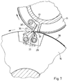
- Fig. 7
- eine Darstellung gemäß Figur 6 mit Darstellung des Falzklappenzylinders und eines Bereichs eines weiteren Falzmesserzylinders,
- Fig. 8
- eine Darstellung gemäß Figur 7, jedoch in späterer, anderer Drehstellung der genannten Zylinder
und - Fig. 9
- eine Schnittdarstellung im Bereich zweier Austragwege der Falzvorrichtung der Figur 1 mit Darstellung eines Bereichs des Falzklappenzylinders sowie zweier Greiferzylinder.
- Fig. 1
- a schematic view of a folder,
- Fig. 2-5
- various products (folding products),
- Fig. 6
- 2 shows a sectional view of an area of a folding knife cylinder and an area of a folding jaw cylinder of the folding apparatus of FIG. 1,
- Fig. 7
- 6 shows a representation of the folding jaw cylinder and a region of a further folding knife cylinder,
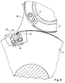
- Fig. 8
- a representation of Figure 7, but in a later, different rotational position of the cylinder mentioned
and - Fig. 9
- a sectional view in the region of two discharge paths of the folding device of Figure 1 showing a region of the jaw cylinder and two gripper cylinders.
Die Figur 1 zeigt - in schematischer Darstellung - einen Falzapparat 1, der einen Falztrichter 2 und eine mittels einer Schere symbolisch angeordnete Längsschneidvorrichtung 3 aufweist. Ferner sind vier Führungswalzenpaare 4, 5, 6 und 7 vorgesehen, die beabstandet zueinander unterhalb des Falztrichters 2 liegen. Zwischen den Führungswalzenpaaren 5 und 6 ist ein Querperforierwerk 8 angeordnet, das gegebenenfalls eingesetzt werden kann. Dem Führungswalzenpaar 6 ist eine Umlenkwalze 9 zugeordnet.FIG. 1 shows - in a schematic representation - a folder 1 which has a former 2 and a
Ferner sind zwei Falzmesserzylinder 10 und 11 vorgesehen, die jeweils mit einem Schneidzylinder 12 beziehungsweise 13 zusammenwirken. Die Falzmesserzylinder 10 und 11 bilden ebenfalls Punkturzylinder. Ein Falzklappenzylinder 14 wirkt mit den beiden Falzmesserzylindern 10 und 11 zusammen und steht ferner in Wirkfunktion mit zwei Greiferzylindern 15 und 16. Zumindest dem Greiferzylinder 15 ist eine Falzmesseranordnung zugeordnet, so daß er gleichzeitig einen Querfalzzylinder bildet.Furthermore, two
An die Greiferzylinder 15 und 16 schließen sich Austragwege 17 beziehungsweise 18 an, denen Längsfalzeinrichtungen 19 beziehungsweise 20 zugeordnet sind. Am Ende der Austragwege 17 und 18 kann jeweils ein Schaufelrad 21 sowie ein Auslageband 22 angeordnet sein, wobei in Figur 1 - der Einfachheit halber - dies nur bei dem unteren Austragweg 18 dargestellt ist.The
In den Falztrichter 2 des Falzapparats 1 läuft eine Bahn 23, beispielsweise eine Papierbahn, ein, die mittels des Falztrichters 2 längsgefalzt oder mittels der Längsschneidvorrichtung 3 in zwei separate Bahnen (Teilbahnen 24 und 25) aufgeteilt und auf dem Trichter aufeinandergewendet wird. Aus den Teilbahnen 24 und 25 werden dann Produkte, vorzugsweise Druckexemplare, durch Abtrennung und Falzung hergestellt. Hierauf wird im nachfolgenden noch näher eingegangen.A
Der Falzklappenzylinder 14 weist mindestens eine, vorzugsweise mehrere als Mehrfachklappen 26 ausgebildete Falzklappen 27 auf und ist auch mit üblichen, einfachen Falzklappen 28 versehen. Nachfolgend wird zunächst auf die verschiedenen Falzprodukte der Figuren 2 bis 5 eingegangen, die unter anderem mittels des Falzapparats 1 herstellbar sind.The
Die Figur 2 zeigt ein zweiteiliges Falzprodukt, wovon jedes Teil eine Querfalzung 29 aufweist. Die beiden Teile liegen mit ihrer Querfalzung 29 deckungsgleich aufeinander und sind mit einer "gemeinsamen" Längsfalzung 30 versehen. Das Wort "gemeinsam" soll andeuten, daß diese Längsfalzung 30 in einem Arbeitsgang bei beiden Teilen gleichzeitig hergestellt worden ist.FIG. 2 shows a two-part folded product, each part of which has a
Die Figur 3 zeigt ein Falzprodukt, das ebenfalls aus zwei Teilen besteht, die - im Gegensatz zum Produkt der Figur 2 - jedoch nicht aufeinander, sondern ineinander liegen.FIG. 3 shows a folded product, which likewise consists of two parts, which - in contrast to the product of FIG. 2 - do not lie on top of one another, but rather one inside the other.
Die Figur 4 betrifft ein Falzprodukt aus zwei Teilen, die entsprechend den Teilen der Figur 2 ausgebildet sind, jedoch nicht aufeinanderliegen, sondern separate Teile (Falzprodukte) bilden, die getrennt in den beiden zweiten Längsfalzen gefalzt wurden.FIG. 4 relates to a folded product made of two parts which are designed like the parts in FIG. 2, but do not lie on top of one another, but instead form separate parts (folded products) which have been folded separately in the two second longitudinal folds.
Die Figur 5 zeigt ein auf dem Falzapparat hergestelltes zweiteiliges Produkt mit getrennten ersten Querfalzen und gemeinsamem zweiten Querfalz.FIG. 5 shows a two-part product produced on the folder with separate first transverse folds and a common second transverse fold.
Aus Figur 6 geht der konstruktive Aufbau der als Mehrfachklappe 26 ausgebildeten Falzklappe 27 näher hervor. Die Mehrfachklappe 26 ist in einer Ausnehmung 31 des Falzklappenzylinders 14 angeordnet. Sie wird im nachfolgenden in Form einer Doppelfalzklappe 32 näher beschrieben. Die Doppelfalzklappe 32 weist einen relativ zum Falzklappenzylinder 14 ortsfesten, unbeweglichen Klemmsteg 33 auf, mit dessen Vorderseite 34 und mit dessen Rückseite 35 jeweils eine verschwenkbar gelagerte Klemmbacke 36 beziehungsweise 37 zusammenwirkt.The structural design of the
Weist die Mehrfachklappe 26 mehr als zwei Klemmbacken auf (nicht dargestellt), so sind entsprechend mehrere Klemmstege mit einer entsprechenden Anzahl von Klemmbacken vorgesehen. Alternativ ist es auch möglich, daß eine Klemmbacke mit dem Rücken der benachbarten Klemmbacke zusammenwirkt.If the
Jede Klemmbacke 36 beziehungsweise 37 besteht aus mehreren, beabstandet voneinander angeordneten, über die Walzenlänge verteilte Klemmstege, so daß das Produkt entlang seiner Länge an mehreren Punkten geklemmt wird.Each clamping
Im nachfolgenden wird die Herstellung des Falzprodukts gemäß Figur 2 näher erläutert. Die dem Falztrichter 2 zugeführte Bahn 23 wird mittels der Längsschneidvorrichtung 3 in die Teilbahnen 24 und 25 aufgeteilt und um 90° längs gedreht. Die Teilbahn 24 wird mittels einer Punkturvorrichtung vom Falzmesserzylinder 10 erfaßt und - am jeweils anderen Ende - mittels des Schneidzylinders 12 abgetrennt. Ein so abgetrenntes Produkt 38 (Figur 6) befindet sich somit auf der Außenmantelfläche des Falzmesserzylinders 10 und wird mit der Drehbewegung dieses Zylinders bis in die in Figur 6 dargestellte Position verbracht. Mittig zur Vorder und Hinterkante des Produkts 38 oder um das halbe Maß des Vor- oder Nachfalzes aus der Mitte verschoben befindet sich am Falzmesserzylinder 10 ein Falzmesser 39, das - sobald die Doppelfalzklappe 32 des Falzklappenzylinders 14 in gegenüberliegende Position tritt - von einer entsprechenden Steuereinrichtung des Falzapparates ausgelöst wird, das heißt, das Falzmesser 39 drückt eine Schlaufe in das Produkt 38, wobei die Schlaufe in dem der Klemmbacke 37 zugeordneten, zum Klemmsteg 33 bestehenden Klemmspalt 40 liegt. Die Klemmbacke 37 schließt und nimmt das Produkt unter Bildung einer Querfalzung 29 - gemäß Figur 7 - im Zuge der weiteren Zylinderdrehung mit.The manufacture of the folded product according to FIG. 2 is explained in more detail below. The
Die Teilbahn 25 wird an einer Walze des Zugwalzenpaares 6 umgelenkt und über die Umlenkwalze 9 geführt sowie dem Falzmesserzylinder 11 zugeleitet. Im Zusammenspiel mit dem Schneidzylinder 13 erfolgt ein entsprechender Schneidvorgang, wie dies bereits im Hinblick auf den Schneidzylinder 12 beschrieben worden ist. Ein entsprechend abgeschnittenes Produkt 38', das von einer Punkturvorrichtung des Falzmesserzylinders 11 gehalten und mitgenommen wird, wird mittels eines Falzmessers 41 in einen Klemmspalt 42 in entsprechender Drehstellung von Falzklappenzylinder 14 und Falzmesserzylinder 11 im Zuge einer Schlaufenbildung eingebracht und dort durch Schließen der Klemmbacke 36 klemmend gehalten und aufgrund der weiteren Drehbewegung der Zylinder 11 und 14 gemäß Figur 7 mitgenommen. Hierdurch wird die Querfalzung 29 am Produkt 38' durchgeführt, wobei die Querfalzungen 29 der Produkte 38 und 38' kantengenau - lediglich durch den schmalen Klemmsteg 33 voneinander getrennt - aufeinanderliegen. Es wird also gleichzeitig beim Falzvorgang ein Zusammenführen der Produkte 38 und 38' vorgenommen.The
Im Zuge des weiteren Betriebs werden die so aufeinandergelegt gehaltenen Produkte 38 und 38' mittels entsprechender Greifer vom Greiferzylinder 15 beziehungsweise 16 übernommen. Es ist möglich, daß nur der Greiferzylinder 15 oder nur der Greiferzylinder 16 die übernahme vornimmt oder daß die Greiferzylinder 15 und 16 alternierend arbeiten, was den Vorteil hat, daß beim folgenden Längsfalzen im zweiten Längsfalz eine doppelt so lange Zeit zur Verfügung steht. Die entsprechenden Produkte werden dann mittels der Längsfalzeinrichtung 19 oder 20 beziehungweise den Längsfalzeinrichtung 19 und 20 längsgefalzt, das heißt, es wird die Längsfalzung 30 durchgeführt. Das so fertiggestellte Produkt wird vom Schaufelrad 21 oder von den Schaufelrädern der zweiten Längsfalze übernommen und den Auslagebändern 22 übergeben.In the course of further operation, the
Um ein Falzprodukt gemäß Figur 3 herzustellen, wird die Bahn 23 im Falztrichter 2 mittels der Längsschneidvorrichtung 3 geteilt und dann aufeinandergewendet. Dann erfolgt jedoch keine Aufteilung der Einzelbahnen 24 und 25, sondern diese bei den Bahnen verlaufen weiterhin parallel zueinander, das heißt sie liegen aufeinander und werden lediglich mit nur einem Falzmesserzylinder (Falzmesserzylinder 10 oder Falzmesserzylinder 11) bearbeitet. Im nachfolgenden soll lediglich auf den Falzmesserzylinder 10 eingegangen werden.In order to produce a folded product according to FIG. 3, the
Nach erfolgter Abtrennung mittels des Schneidzylinders 12 gelangen die beiden übereinanderliegenden Stücke der Teilbahnen 24 und 25 zum Falzklappenzylinder 14, indem sie mittels eines Falzmessers des Falzmesserzylinders 10 von einer Klemmbacke 36 beziehungsweise 37 der Doppelfalzklappe 32 erfaßt und festgehalten werden, das heißt, die Doppelfalzklappe 32 wird nicht für eine Doppelklemmung genutzt, sondern wie eine einfach Falzklappe gebraucht. Die so gemeinsam quergefalzten Teile werden wahlweise der oberen oder der unteren Auslage mittels des Greiferzylinders 15 oder 16 zugeführt. Es ist auch denkbar, daß eine alternierende Auslage über beide Greiferzylinder 15 und 16 erfolgt, was eine erhöhte Geschwindigkeit zuläßt. Im Zuge der Austragung erfolgt dann eine entsprechende Längsfalzung mit Hilfe der Längsfalzeinrichtung 19 und/oder 20. Bei allen hier beschriebenen Ausführungsbeispielen sind die Austragwege 17 und 18 vorzugsweise als Bänderstrecken ausgebildet.After separation by means of the cutting cylinder 12, the two pieces of the
Zur Erstellung des Produkts gemäß Figur 4 erfolgt der Ablauf ebenso wie bei der Erstellung des Produkts gemäß Figur 2. Lediglich bei der übergabe der Produkte 38 und 38' zu den Greiferzylindern 15 und 16 sind Besonderheiten vorgesehen, die nachfolgend erläutert werden.The procedure for creating the product according to FIG. 4 is the same as for creating the product according to FIG. 2. Only when the
Aus der Figur 1 ist ersichtlich, daß der Greiferzylinder 15 unterschiedliche Greifer, nämlich kurze Greifer 42 und lange Greifer 43 aufweist. Dies geht besonders deutlich aus der Figur 9 hervor. Mittels der langen Greifer 43, die als normale Greifer anzusehen sind und die auch bei dem Greiferzylinder 16 vorhanden sind, werden alle einzelnen Klemmbacken 36 und 37 einer Mehrfachklappe 26 gehaltenen Produkte 38, 38' erfaßt und übernommen. Kommt jedoch - gemäß Figur 9 - der kurze Greifer 42 des Greiferzylinders 15 zum Einsatz, so entnimmt dieser lediglich das Produkt 38 der - in Drehrichtung gesehen - vorauseilenden Klemmbacke 36, während - im Zuge der weiteren Drehung - der (lange) Greifer 43 des Greiferzylinders 16 das Produkt 38' von der nacheilenden Klemmbacke 37 übernimmt. Auf diese Art und Weise ist es also möglich, die Produkte 38 und 38' wieder zu trennen und entsprechend den Austragwegen 17 und 18 zuzuführen. Hierdurch entsteht - jeweils nach Durchführung der noch fehlenden Längsfalzung - das Produkt der Figur 4.It can be seen from FIG. 1 that the
Neben der Querfalzung 29 der Produkte ist - gemäß Figur 1 - im Zusammenspiel von Falzklappenzylinder 14 und Greiferzylinder 15 eine weitere Querfalzung möglich. Dies kann beispielsweise bei den Produkten gemäß Figur 2 und 3 durchgeführt werden. Eine derartige Anordnung kann auch zum Einsatz kommen, um Delta-Falzungen durchzuführen. Hierzu ist dann ein entsprechender Versatz der Einrichtungen erforderlich. Um die zweite Querfalzung vornehmen zu können wird das entsprechende Produkt von den entsprechenden Greifern des Greiferzylinders 15 übernommen, wobei jedoch keine Austragung erfolgt. Vielmehr ist am Greiferzylinder 15 mindestens eine Falzmesseranordnung 44 vorgesehen, die eine Schlaufe des Produkts in eine entsprechende einfache Falzklappe 28 des Falzklappenzylinders 14 einbringt. Durch Schließen der Falzklappe 28 wird diese Schlaufe als zweite Querfalzung ausgebildet und das Produkt entsprechend unter öffnen der Greifer des Greiferzylinders 15 von dem Falzklappenzylinder 14 mitgenommen und schließlich mittels des Greiferzylinders 16 ausgetragen. Hierdurch ist es möglich, Produkte entsprechend Figur 5 herzustellen.In addition to the
Bei der Wahl des Einsatzes eines kurzen Greifers 42 oder eines langen Greifers 43 wird ein entsprechender Drehstellungsversatz zwischen dem Falzklappenzylinder 14 und dem Greiferzylinder 15 vorgenommen. Aufgrund der Mehrfachklappe 26 sind die dort gehaltenen Falze umfangseitig geringfügig versetzt. Dies könnte zu einer Abweichung der übereinanderlage der Produkte führen. Ein Ausgleich ist dadurch möglich, daß die entsprechenden Falzmesser unterschiedlich weit in den Klemmspalt eindringen, wodurch eine entsprechend mehr oder weniger große Schlaufe gebildet wird, was zur Kompensation führt.When choosing to use a
Claims (10)
dadurch gekennzeichnet,
daß der Falzklappenzylinder (14) mindestens eine als Mehrfachklappe (26) ausgebildete Falzklappe (27) besitzt, die mehrere, aneinandergrenzende Klemmbacken (36, 37) zum gleichzeitig beim Querfalzen erfolgenden zusammenführenden Halten von mehreren Produkten (38, 38') aufweist.Folding apparatus for transverse folding of products, preferably printed copies, separated from a web, in particular by means of a longitudinal cutting device, with at least one transverse folding device which has a folding knife cylinder and a folding jaw cylinder,
characterized by
that the folding jaw cylinder (14) has at least one folding jaw (27) designed as a multiple jaw (26), which has a plurality of adjoining clamping jaws (36, 37) for simultaneously holding together several products (38, 38 ') during transverse folding.
dadurch gekennzeichnet,
daß dem Falzklappenzylinder (14) mehrere Falzmesserzylinder (10, 11) für jeweils separate Bahnen (Teilbahn 24, Teilbahn 25) zugeordnet sind.Folding apparatus according to claim 1,
characterized by
that the folding jaw cylinder (14) is assigned a plurality of folding knife cylinders (10, 11) for separate webs (partial web 24, partial web 25).
dadurch gekennzeichnet,
daß die Falzmesserzylinder (10, 11) Haltevorrichtungen, insbesondere Punkturvorrichtungen oder Greifer, für die Produkte (38, 38') aufweisen.Folding apparatus according to one of the preceding claims,
characterized by
that the folding knife cylinders (10, 11) have holding devices, in particular puncturing devices or grippers, for the products (38, 38 ').
dadurch gekennzeichnet,
daß dem Falzklappenzylinder (14) mehrere Greiferzylinder (15, 16) für die wahlweise mögliche Zuleitung der Produkte (38, 38') zu unterschiedlichen Austragwegen (17, 18) zugeordnet sind.Folding apparatus according to one of the preceding claims,
characterized by
that the jaw cylinder (14) is assigned a plurality of gripper cylinders (15, 16) for the optionally possible supply of the products (38, 38 ') to different discharge paths (17, 18).
dadurch gekennzeichnet,
daß mindestens einer der Greiferzylinder (15, 16) eine Falzmesseranordnung (44) aufweist, die mit dem Falzklappenzylinder (14) zusammenwirkt.Folding apparatus according to one of the preceding claims,
characterized by
that at least one of the gripper cylinders (15, 16) has a folding knife arrangement (44) which interacts with the folding jaw cylinder (14).
dadurch gekennzeichnet,
daß mindestens einem der Austragwege (17, 18) eine Längsfalzeinrichtung (19, 20) zugeordnet ist.Folding apparatus according to one of the preceding claims,
characterized by
that at least one of the discharge paths (17, 18) is assigned a longitudinal folding device (19, 20).
dadurch gekennzeichnet,
daß mindestens einer der Greiferzylinder (15, 16) derart ausgebildete beziehungsweise angeordnete Greifer (42, 43) aufweist, daß diese nur mit einer, insbesondere - in Drehrichtung des Falzklappenzylinders gesehen - voreilenden Klemmbacke oder einigen der Klemmbacken der Mehrfachklappe (26) zusammenwirkt.Folding apparatus according to one of the preceding claims,
characterized by
that at least one of the gripper cylinders (15, 16) has grippers (42, 43) designed or arranged in such a way that they cooperate only with a leading jaw, particularly as seen in the direction of rotation of the folding jaw cylinder, or with some of the jaws of the multiple flap (26).
dadurch gekennzeichnet,
daß die Mehrfachklappe (26) als Doppelfalzklappe (32) ausgebildet ist.Folding apparatus according to one of the preceding claims,
characterized by
that the multiple flap (26) is designed as a double folding flap (32).
dadurch gekennzeichnet,
daß die Doppelfalzklappe (32) einen zylinderfesten Klemmsteg (33) aufweist, mit dessen Vorder- und Rückseite (34, 35) jeweils eine Klemmbacke (36, 37) zusammenwirkt.Folding apparatus according to one of the preceding claims,
characterized by
that the double rebate flap (32) has a cylinder-fixed clamping web (33), with the front and rear (34, 35) of which a jaw (36, 37) cooperates.
Die Produkte werden zur Querfalzung von einem Falzmesser eines Falzmesserzylinders beaufschlagt und im Falzbereich zum Halten festgeklemmt, wobei gleichzeitig beim Festklemmen eine übergabe vom Falzmesserzylinder zu einem Falzklappenzylinder erfolgt, insbesondere zum Betrieb des Falzapparates nach einem oder mehreren der vorhergehenden Ansprüche 1 bis 9,
dadurch gekennzeichnet,
daß mindestens zwei Produkte während des Falzvorganges derart zusammengeführt und dabei getrennt am Falzklappenzylinder derart gehalten werden, daß sie in einer gewünschten Relativposition, insbesondere mit deckungsgleichen oder etwa deckungsgleichen Falzkanten benachbart zueinander angeordnet sind.Process for the transverse folding of products separated from a web, in particular by means of a longitudinal cutting device from a longitudinally cut partial web, preferably printed copies, with the following process steps:
The products are acted upon by a folding knife of a folding knife cylinder for transverse folding and clamped in the folding area for holding, while at the same time a transfer takes place from the folding knife cylinder to a folding jaw cylinder when clamping, in particular for operating the folding apparatus according to one or more of the preceding claims 1 to 9,
characterized by
that at least two products are brought together during the folding process and held separately on the folding jaw cylinder in such a way that they are arranged adjacent to one another in a desired relative position, in particular with congruent or approximately congruent folding edges.
Applications Claiming Priority (2)
| Application Number | Priority Date | Filing Date | Title |
|---|---|---|---|
| DE4316134A DE4316134C2 (en) | 1993-05-13 | 1993-05-13 | Process for the transverse folding of webs and folder for carrying out the process |
| DE4316134 | 1993-05-13 |
Publications (2)
| Publication Number | Publication Date |
|---|---|
| EP0627310A1 true EP0627310A1 (en) | 1994-12-07 |
| EP0627310B1 EP0627310B1 (en) | 1998-06-24 |
Family
ID=6488068
Family Applications (1)
| Application Number | Title | Priority Date | Filing Date |
|---|---|---|---|
| EP94106087A Expired - Lifetime EP0627310B1 (en) | 1993-05-13 | 1994-04-20 | Folding apparatus and method for crosswise folding |
Country Status (3)
| Country | Link |
|---|---|
| US (1) | US5494270A (en) |
| EP (1) | EP0627310B1 (en) |
| DE (2) | DE4316134C2 (en) |
Cited By (3)
| Publication number | Priority date | Publication date | Assignee | Title |
|---|---|---|---|---|
| WO2003074402A1 (en) | 2002-03-04 | 2003-09-12 | Koenig & Bauer Aktiengesellschaft | Cutting device for the transverse cutting of at least one material web |
| WO2004096687A1 (en) | 2003-05-02 | 2004-11-11 | Koenig & Bauer Aktiengesellschaft | Rotary folder comprising a cutting device for cross-cutting at least one web |
| CN103381698A (en) * | 2005-12-27 | 2013-11-06 | 高斯国际美洲公司 | Roadsheet newspaper printing press and folder |
Families Citing this family (21)
| Publication number | Priority date | Publication date | Assignee | Title |
|---|---|---|---|---|
| EP0836938B1 (en) * | 1996-10-15 | 2000-07-05 | Komori Corporation | Pinless folder |
| EP1119453A4 (en) * | 1998-03-20 | 2007-01-17 | Specialty Systems Advanced Mac | High speed paper folding machine |
| JP2002523319A (en) * | 1998-08-18 | 2002-07-30 | ハイデルベルガー ドルツクマシーネン アクチエンゲゼルシヤフト | Method and apparatus for perforating material web |
| US6038974A (en) * | 1998-11-05 | 2000-03-21 | Heidelberger Druckmaschinen Ag | Gripper deceleration cross folder |
| US6322487B1 (en) * | 1998-12-09 | 2001-11-27 | Heidelberger Druckmaschinen Ag | Method and apparatus for delivery of flat printed products |
| EP1074500B1 (en) * | 1999-08-05 | 2004-10-27 | Heidelberger Druckmaschinen Aktiengesellschaft | Printed products transport cylinder of a folding apparatus |
| US6923752B1 (en) | 2000-04-18 | 2005-08-02 | Goss International Americas, Inc. | Folding cylinder with expansion segment |
| US7011617B2 (en) * | 2001-04-10 | 2006-03-14 | Goss International Americas, Inc. | Folder with group jaw adjustment |
| DE10128122A1 (en) * | 2001-06-09 | 2002-12-12 | Roland Man Druckmasch | Drive for a folder |
| JP3442062B2 (en) * | 2001-06-11 | 2003-09-02 | 株式会社東京機械製作所 | Folding device |
| US6733431B2 (en) * | 2001-09-19 | 2004-05-11 | Heidelberger Druckmaschinen Ag | Device and method for folding newspapers with flexible inserting position |
| DE10156706B4 (en) * | 2001-11-17 | 2016-04-28 | Manroland Web Systems Gmbh | Variable size folder |
| DE10209213B4 (en) * | 2002-03-04 | 2004-03-25 | Koenig & Bauer Ag | transport device |
| US6644193B2 (en) | 2002-03-12 | 2003-11-11 | Elsner Engineering Works, Inc. | Web cutting tuck folding machine and method |
| DE102004002348A1 (en) * | 2004-01-16 | 2005-08-11 | Koenig & Bauer Ag | folding |
| JP4267512B2 (en) * | 2004-04-30 | 2009-05-27 | 株式会社小森コーポレーション | Parallel folding device of folding machine |
| DE102006042592B4 (en) * | 2006-09-11 | 2009-04-09 | Koenig & Bauer Aktiengesellschaft | folding |
| JP2008120489A (en) * | 2006-11-09 | 2008-05-29 | Mitsubishi Heavy Ind Ltd | Signature conveyance path switching structure and folding machine |
| JP4719133B2 (en) * | 2006-11-21 | 2011-07-06 | 株式会社東京機械製作所 | Frustration device |
| US20110025039A1 (en) * | 2009-08-03 | 2011-02-03 | Manugraph DGM, Inc. | method and apparatus for making a sectioned tab product |
| ATE552197T1 (en) | 2009-10-23 | 2012-04-15 | Mueller Martini Holding Ag | METHOD FOR PRODUCING A PRINTED PRODUCT |
Citations (1)
| Publication number | Priority date | Publication date | Assignee | Title |
|---|---|---|---|---|
| DE3614263A1 (en) * | 1986-04-26 | 1987-10-29 | Roland Man Druckmasch | FOLDING APPARATUS WITH A SECOND AND THIRD FOLD |
Family Cites Families (9)
| Publication number | Priority date | Publication date | Assignee | Title |
|---|---|---|---|---|
| US512944A (en) * | 1894-01-16 | Paper-folder | ||
| DE449118C (en) * | 1926-08-03 | 1927-09-06 | Koenig & Bauer Schnellpressfab | Folding device for rotary printing machines |
| JPS5019971B1 (en) * | 1970-01-14 | 1975-07-11 | ||
| JPS54154622A (en) * | 1978-05-26 | 1979-12-05 | Toshiba Mach Co Ltd | Paper folding apparatus for rotary press |
| DE2846191C3 (en) * | 1978-10-24 | 1981-08-13 | Koenig & Bauer AG, 8700 Würzburg | Folder for web-fed rotary printing machines |
| DE2920625A1 (en) * | 1979-05-22 | 1980-11-27 | Maschf Augsburg Nuernberg Ag | FOLDING DEVICE FOR A ROTARY PRINTING MACHINE |
| US4754959A (en) * | 1985-08-02 | 1988-07-05 | M.A.N. Roland Druckmaschinen Aktiengesellschaft | Folding apparatus for transverse folding and transporting of two types of printed substrates |
| DE3527710A1 (en) * | 1985-08-02 | 1987-02-12 | Roland Man Druckmasch | FOLDING APPARATUS FOR CROSS FOLDING PRINTED COPIES |
| DE4208353A1 (en) * | 1992-03-16 | 1993-09-23 | Heidelberger Druckmasch Ag | ROTARY FOLDING APPARATUS WITH SPECIAL CYLINDER ARRANGEMENT FOR ROLE ROTATION PRINTING MACHINES |
-
1993
- 1993-05-13 DE DE4316134A patent/DE4316134C2/en not_active Expired - Fee Related
-
1994
- 1994-04-20 EP EP94106087A patent/EP0627310B1/en not_active Expired - Lifetime
- 1994-04-20 DE DE59406307T patent/DE59406307D1/en not_active Expired - Fee Related
- 1994-05-13 US US08/242,120 patent/US5494270A/en not_active Expired - Fee Related
Patent Citations (1)
| Publication number | Priority date | Publication date | Assignee | Title |
|---|---|---|---|---|
| DE3614263A1 (en) * | 1986-04-26 | 1987-10-29 | Roland Man Druckmasch | FOLDING APPARATUS WITH A SECOND AND THIRD FOLD |
Cited By (7)
| Publication number | Priority date | Publication date | Assignee | Title |
|---|---|---|---|---|
| WO2003074402A1 (en) | 2002-03-04 | 2003-09-12 | Koenig & Bauer Aktiengesellschaft | Cutting device for the transverse cutting of at least one material web |
| DE10209190A1 (en) * | 2002-03-04 | 2003-09-25 | Koenig & Bauer Ag | Cutting device for cross cutting at least one material web |
| DE10209190B4 (en) * | 2002-03-04 | 2004-03-04 | Koenig & Bauer Ag | Cutting device for cross cutting at least one material web |
| US7351189B2 (en) | 2002-03-04 | 2008-04-01 | Koenig & Bauer Aktiengesellschaft | Cutting device for the transverse cutting of at least one material web |
| EP2030935A1 (en) | 2002-03-04 | 2009-03-04 | Koenig & Bauer Aktiengesellschaft | Cutting device for the transverse cutting of at least one material web |
| WO2004096687A1 (en) | 2003-05-02 | 2004-11-11 | Koenig & Bauer Aktiengesellschaft | Rotary folder comprising a cutting device for cross-cutting at least one web |
| CN103381698A (en) * | 2005-12-27 | 2013-11-06 | 高斯国际美洲公司 | Roadsheet newspaper printing press and folder |
Also Published As
| Publication number | Publication date |
|---|---|
| DE4316134C2 (en) | 1997-03-13 |
| DE59406307D1 (en) | 1998-07-30 |
| EP0627310B1 (en) | 1998-06-24 |
| US5494270A (en) | 1996-02-27 |
| DE4316134A1 (en) | 1994-11-17 |
Similar Documents
| Publication | Publication Date | Title |
|---|---|---|
| EP0627310B1 (en) | Folding apparatus and method for crosswise folding | |
| EP0165599B1 (en) | Folder unit for ribbon folding on a reel-fed rotary printing press | |
| EP0023630B1 (en) | Folding device for rotary web-printing machines | |
| DE3527710C2 (en) | ||
| DE2120903C3 (en) | Device for folding webs into multiple folded individual products | |
| EP0408912B1 (en) | Method and device for production of paperstacks | |
| EP0257390B1 (en) | Folding apparatus | |
| EP0659555B1 (en) | Device for producing folded products | |
| DE2921383C2 (en) | Paper folding machine for use on a rotary printing press | |
| DE2517000C2 (en) | Folding device for transversely and longitudinally folded or only longitudinally folded products | |
| DE3614263C2 (en) | ||
| DE1611283C2 (en) | Cutting and folding device on web-fed rotary machines | |
| DE3925398C1 (en) | ||
| EP0151412B1 (en) | Folding apparatus in a rotary printing machine | |
| DE2512368B2 (en) | Folding device with two longitudinal folding devices | |
| DE19856422A1 (en) | Web feed for a folder | |
| DE10238736A1 (en) | Method and device for folding a printed product | |
| EP0520246B1 (en) | Device for transversally folding webs from a rotary press | |
| DE3636246C2 (en) | ||
| DE3636244C2 (en) | ||
| EP1718463B1 (en) | Printing machine comprising a former | |
| EP1013590B1 (en) | Device for folding and transporting flat printed products in a rotary printing machine | |
| DE449118C (en) | Folding device for rotary printing machines | |
| EP1483189A1 (en) | Cutting device | |
| DE102009052145A1 (en) | Folding machine with a device for pressing |
Legal Events
| Date | Code | Title | Description |
|---|---|---|---|
| PUAI | Public reference made under article 153(3) epc to a published international application that has entered the european phase |
Free format text: ORIGINAL CODE: 0009012 |
|
| 17P | Request for examination filed |
Effective date: 19940420 |
|
| AK | Designated contracting states |
Kind code of ref document: A1 Designated state(s): CH DE FR GB LI |
|
| GBC | Gb: translation of claims filed (gb section 78(7)/1977) | ||
| 17Q | First examination report despatched |
Effective date: 19960731 |
|
| GRAG | Despatch of communication of intention to grant |
Free format text: ORIGINAL CODE: EPIDOS AGRA |
|
| GRAG | Despatch of communication of intention to grant |
Free format text: ORIGINAL CODE: EPIDOS AGRA |
|
| GRAH | Despatch of communication of intention to grant a patent |
Free format text: ORIGINAL CODE: EPIDOS IGRA |
|
| GRAH | Despatch of communication of intention to grant a patent |
Free format text: ORIGINAL CODE: EPIDOS IGRA |
|
| GRAA | (expected) grant |
Free format text: ORIGINAL CODE: 0009210 |
|
| AK | Designated contracting states |
Kind code of ref document: B1 Designated state(s): CH DE FR GB LI |
|
| REG | Reference to a national code |
Ref country code: CH Ref legal event code: EP |
|
| REF | Corresponds to: |
Ref document number: 59406307 Country of ref document: DE Date of ref document: 19980730 |
|
| GBT | Gb: translation of ep patent filed (gb section 77(6)(a)/1977) |
Effective date: 19980902 |
|
| ET | Fr: translation filed | ||
| PLBE | No opposition filed within time limit |
Free format text: ORIGINAL CODE: 0009261 |
|
| STAA | Information on the status of an ep patent application or granted ep patent |
Free format text: STATUS: NO OPPOSITION FILED WITHIN TIME LIMIT |
|
| 26N | No opposition filed | ||
| REG | Reference to a national code |
Ref country code: GB Ref legal event code: IF02 |
|
| PGFP | Annual fee paid to national office [announced via postgrant information from national office to epo] |
Ref country code: GB Payment date: 20060410 Year of fee payment: 13 |
|
| PGFP | Annual fee paid to national office [announced via postgrant information from national office to epo] |
Ref country code: FR Payment date: 20060418 Year of fee payment: 13 |
|
| PGFP | Annual fee paid to national office [announced via postgrant information from national office to epo] |
Ref country code: CH Payment date: 20060421 Year of fee payment: 13 |
|
| PGFP | Annual fee paid to national office [announced via postgrant information from national office to epo] |
Ref country code: DE Payment date: 20060508 Year of fee payment: 13 |
|
| REG | Reference to a national code |
Ref country code: CH Ref legal event code: PL |
|
| GBPC | Gb: european patent ceased through non-payment of renewal fee |
Effective date: 20070420 |
|
| PG25 | Lapsed in a contracting state [announced via postgrant information from national office to epo] |
Ref country code: DE Free format text: LAPSE BECAUSE OF NON-PAYMENT OF DUE FEES Effective date: 20071101 |
|
| PG25 | Lapsed in a contracting state [announced via postgrant information from national office to epo] |
Ref country code: CH Free format text: LAPSE BECAUSE OF NON-PAYMENT OF DUE FEES Effective date: 20070430 Ref country code: LI Free format text: LAPSE BECAUSE OF NON-PAYMENT OF DUE FEES Effective date: 20070430 |
|
| PG25 | Lapsed in a contracting state [announced via postgrant information from national office to epo] |
Ref country code: GB Free format text: LAPSE BECAUSE OF NON-PAYMENT OF DUE FEES Effective date: 20070420 |
|
| PG25 | Lapsed in a contracting state [announced via postgrant information from national office to epo] |
Ref country code: FR Free format text: LAPSE BECAUSE OF NON-PAYMENT OF DUE FEES Effective date: 20070430 |