EP0628810A2 - Electrochemical analyser for gas traces with functioning check - Google Patents
Electrochemical analyser for gas traces with functioning check Download PDFInfo
- Publication number
- EP0628810A2 EP0628810A2 EP94250126A EP94250126A EP0628810A2 EP 0628810 A2 EP0628810 A2 EP 0628810A2 EP 94250126 A EP94250126 A EP 94250126A EP 94250126 A EP94250126 A EP 94250126A EP 0628810 A2 EP0628810 A2 EP 0628810A2
- Authority
- EP
- European Patent Office
- Prior art keywords
- electrode
- sensor
- test
- working electrode
- measuring system
- Prior art date
- Legal status (The legal status is an assumption and is not a legal conclusion. Google has not performed a legal analysis and makes no representation as to the accuracy of the status listed.)
- Withdrawn
Links
Images

Classifications
-
- G—PHYSICS
- G01—MEASURING; TESTING
- G01N—INVESTIGATING OR ANALYSING MATERIALS BY DETERMINING THEIR CHEMICAL OR PHYSICAL PROPERTIES
- G01N27/00—Investigating or analysing materials by the use of electric, electrochemical, or magnetic means
- G01N27/26—Investigating or analysing materials by the use of electric, electrochemical, or magnetic means by investigating electrochemical variables; by using electrolysis or electrophoresis
- G01N27/416—Systems
- G01N27/4163—Systems checking the operation of, or calibrating, the measuring apparatus
-
- G—PHYSICS
- G01—MEASURING; TESTING
- G01D—MEASURING NOT SPECIALLY ADAPTED FOR A SPECIFIC VARIABLE; ARRANGEMENTS FOR MEASURING TWO OR MORE VARIABLES NOT COVERED IN A SINGLE OTHER SUBCLASS; TARIFF METERING APPARATUS; MEASURING OR TESTING NOT OTHERWISE PROVIDED FOR
- G01D18/00—Testing or calibrating apparatus or arrangements provided for in groups G01D1/00 - G01D15/00
- G01D18/002—Automatic recalibration
- G01D18/006—Intermittent recalibration
-
- G—PHYSICS
- G01—MEASURING; TESTING
- G01N—INVESTIGATING OR ANALYSING MATERIALS BY DETERMINING THEIR CHEMICAL OR PHYSICAL PROPERTIES
- G01N33/00—Investigating or analysing materials by specific methods not covered by groups G01N1/00 - G01N31/00
- G01N33/0004—Gaseous mixtures, e.g. polluted air
- G01N33/0009—General constructional details of gas analysers, e.g. portable test equipment
- G01N33/0062—General constructional details of gas analysers, e.g. portable test equipment concerning the measuring method, e.g. intermittent, or the display, e.g. digital
- G01N33/0063—General constructional details of gas analysers, e.g. portable test equipment concerning the measuring method, e.g. intermittent, or the display, e.g. digital using a threshold to release an alarm or displaying means
Abstract
Description
Die Erfindung geht aus von einem Gasspurenmeßsystem, das aus einem elektrochemischen Sensor mit mindestens einer Arbeitselektrode, einer Gegenelektrode und gegebenenfalls einer Referenzelektrode besteht und eine analoge Auswerteelektronik zur Bildung von Meßwerten aufweist.The invention is based on a gas trace measuring system which consists of an electrochemical sensor with at least one working electrode, a counter electrode and optionally a reference electrode and has an analog evaluation electronics for the formation of measured values.
Elektrochemische Gassensoren werden für Arbeits- und Umweltschutzzwecke vielfach zur Messung von Gasspuren bis in den ppb-Bereich eingesetzt. Ein typischer Zweielektrodensensor mit einer Arbeits- und Gegenelektrode ist z.B. in DE 24 36 261 und ein typischer Dreielektrodensensor mit einer Arbeitselektrode, einer Gegenelektrode und einer Referenzelektrode in DE 21 55 935 beschrieben. Mehrfachelektrodensensoren mit mehreren Arbeitselektroden zur simultanen Messung verschiedener Gaskomponenten sind aus DE 24 35 813 und DE 41 36 779 bekannt. Ein generelles Problem solcher Sensoren ist die Zuverlässigkeit und Verfügbarkeit der Meßwerte. Eine Fehlfunktion der Meßzelle muß in jedem Fall rechtzeitig erkannt werden, um Folgeschäden für den Anwender des Gerätes auszuschließen. Aus diesen Gründen ist es üblich, die Geräte vor der Benutzung einer Funktionskontrolle zu unterziehen. Zu diesem Zweck wird der Sensor kurzzeitig mit einem Testgas beaufschlagt und das dabei erzeugte Meßsignal mit einem Sollwert verglichen. Ein derartiger Funktionstest wird in DE 26 21 677 und DE 31 29 680 beschrieben. Ferner ist ein elektrochemischer Mehrfachelektrodensensor bekannt, bei dem die Arbeitselektroden gleichzeitig der zu messenden Gaskonzentration ausgesetzt werden und bei einem zu großen Unterschied der Meßsignale an den Arbeitselektroden eine Warnanzeige erfolgt. In diesem Fall beruht also die Funktionsüberwachung auf redundanten Meßzellen bzw. Arbeitselektroden. Ein nach diesem Prinzip arbeitender elektrochemischer Gassensor wird in DE 26 58 734 beschrieben. Derartige Anordnungen sind jedoch zwangsläufig mit einem größeren apparativen und schaltungstechnischen Aufwand verbunden.Electrochemical gas sensors are often used for work and environmental protection purposes to measure gas traces down to the ppb range. A typical two-electrode sensor with a working and counter electrode is described, for example, in DE 24 36 261 and a typical three-electrode sensor with a working electrode, a counter electrode and a reference electrode in DE 21 55 935. Multiple electrode sensors with several working electrodes for the simultaneous measurement of different gas components are known from DE 24 35 813 and DE 41 36 779. A general problem of such sensors is the reliability and availability of the measured values. A malfunction of the measuring cell must be recognized in good time in order to prevent consequential damage for the user of the device. For these reasons, it is customary to have the devices checked before they are used. For this purpose, the sensor is briefly subjected to a test gas and the measurement signal generated is compared with a target value. Such a function test is described in DE 26 21 677 and DE 31 29 680. Furthermore, an electrochemical multiple electrode sensor is known in which the working electrodes are simultaneously exposed to the gas concentration to be measured and a warning is displayed if the measuring signals on the working electrodes differ too much. In this case, the function monitoring is based on redundant measuring cells or working electrodes. An electrochemical based on this principle Gas sensor is described in DE 26 58 734. However, such arrangements are inevitably associated with a greater outlay in terms of apparatus and circuitry.
Hier setzt die Erfindung an. Es liegt die Aufgabe zugrunde, ein Gasspurenmeßsystem auf der Basis von herkömmlichen elektrochemischen Zwei- oder Dreielektrodensensoren (in abgewandelter Form auch Multielektrodensensoren) zu entwickeln, bei dem jederzeit, d.h. auch am Einsatzort, ein einfacher elektrischer Funktionstest durchgeführt werden kann.This is where the invention comes in. The object of the invention is to develop a gas trace measuring system based on conventional electrochemical two- or three-electrode sensors (in a modified form also multi-electrode sensors), in which at any time, i.e. a simple electrical function test can also be carried out on site.
Diese Aufgabe wird erfindungsgemäß dadurch gelost, daß die im Gasspurenmeßsystem bereits vorhandene Auswerteelektronik zusätzlich mit einer Diagnoseschaltung versehen wird, die während eines Testzyklus das zwischen Arbeitselektrode und Gegenelektrode oder zwischen Arbeitselektrode und Referenzelektrode eingestellte Potential nach einer vorgegebenen Zeitfunktion vorübergehend verändert und die dadurch erzeugte Stromsignaländerung an der Arbeitselektrode als ein für die Sensorqualität repräsentatives Testsignal ausgibt und mit einem oder mehreren vorgegebenen Sollwerten vergleicht. Die Diagnoseschaltung ist dabei so ausgeführt, daß von dem normalen Meßmodus auf einen Testmodus umgeschaltet werden kann. Im Testmodus wird dann dem Potential an der Arbeitselektrode vorübergehend eine Testspannung überlagert und die dadurch erzeugte Stromsignaländerung (Sensorantwort) als Testsignal ausgewertet und mit bekannten Daten, die eine fehlerfrei funktionierende Sensorzelle liefert, verglichen. Auf diese Weise kann eine defekte Sensorzelle schnell erkannt werden.This object is achieved according to the invention in that the evaluation electronics already present in the gas trace measuring system are additionally provided with a diagnostic circuit which temporarily changes the potential set between working electrode and counter electrode or between working electrode and reference electrode after a predetermined time function during a test cycle and the current signal change thereby generated on the Outputs the working electrode as a test signal representative of the sensor quality and compares it with one or more predetermined target values. The diagnostic circuit is designed so that it can be switched from the normal measurement mode to a test mode. In the test mode, a test voltage is then temporarily superimposed on the potential at the working electrode, and the current signal change (sensor response) generated in this way is evaluated as a test signal and compared with known data that a sensor cell that functions correctly. In this way, a defective sensor cell can be quickly identified.
Es ist auch möglich, durch eine Messung der zeitlichen Änderung des Testsignals eine Information über die Ansprechzeit des Sensors (Responsekurve) zu erhalten. In diesem Fall wird dem Potential an der Arbeitselektrode zweckmäßig ein Rechteckimpuls überlagert.It is also possible to obtain information about the response time of the sensor (response curve) by measuring the change in the test signal over time. In this case, a square pulse is expediently superimposed on the potential at the working electrode.
Anstelle eines direkten Vergleichs der durch das Testsignal erzeugten Stromsignaländerung an der Arbeitselektrode (Sensorantwort) kann gemäß einer bevorzugten Ausführungsform das Testsignal auch dadurch erzeugt werden, daß das Stromsignal an der Arbeitselektrode während des Testzyklus aufintegriert wird.Instead of a direct comparison of the current signal change on the working electrode (sensor response) generated by the test signal, according to a preferred Embodiment, the test signal can also be generated by integrating the current signal on the working electrode during the test cycle.
Gemäß einer Weiterentwicklung der Erfindung wird bei einem elektrochemischen Drei- oder Mehrelektrodensensor mit einer analogen potentiostatischen Auswerteelektronik das Potential zwischen Arbeitselektrode und Referenzelektrode während des Testzyklus nach Art eines differentiellen zyklischen Voltagramms mit einer Wechselspannung moduliert und durch Integration des in die Arbeitselektrode fließenden Stromsignals über eine Periode der Wechselspannung die von der dabei durchlaufenen Strom-Spannungshysteresekurve eingeschlossene Flache als Testsignal ausgewertet.According to a further development of the invention, the potential between the working electrode and the reference electrode is modulated with an AC voltage during the test cycle in the manner of a differential cyclic voltagram in an electrochemical three- or multi-electrode sensor with an analog potentiostatic evaluation electronics and by integrating the current signal flowing into the working electrode over a period of AC voltage evaluates the area enclosed by the current-voltage hysteresis curve traversed as a test signal.
Vorteilhaft weist die Diagnoseschaltung einen Komparator zum Vergleich des Testsignals mit einem oder mehreren vorgegebenen, gespeicherten Sollwerten auf. Bei einer unzulässigen Abweichung von den Sollwerten kann dann ein akustischer oder optischer Alarm (Blinken) ausgelöst werden.The diagnostic circuit advantageously has a comparator for comparing the test signal with one or more predetermined, stored target values. In the event of an impermissible deviation from the target values, an acoustic or visual alarm (flashing) can then be triggered.
In der Praxis wird die Diagnoseschaltung zweckmäßig so ausgeführt, daß sämtliche beschriebenen elektronischen Testfunktionen in einem mit der Auswerteelektronik in Verbindung stehenden Rechner als Software implementiert sind.In practice, the diagnostic circuit is expediently carried out in such a way that all the electronic test functions described are implemented as software in a computer connected to the evaluation electronics.
Mit der Erfindung werden folgende Vorteile erzielt:
- Das Gasspurenmeßsystem mit integrierter Diagnoseschaltung erlaubt eine einfache elektrische Funktionsüberwachung, mit der die Betriebsbereitschaft des Geräts jederzeit überprüft werden kann. Insbesondere werden keine zusätzlichen Gerätekomponenten, wie z.B. Kalibriereinheiten, benötigt. Durch die Diagnoseschaltung können die für die Erzeugung des Meßsignals verantwortlichen elektrochemischen Reaktionen in der Meßzelle kontrolliert werden. Zusätzlich wird die Funktion der analogen Meßwertverarbeitung in der Auswerteelektronik überwacht. Beim Auftreten eines Fehlersignals kann ein Alarm ausgelöst werden oder auf eine zweite, parallel betriebene Sensorzelle umgeschaltet werden.
- Da für den Testzyklus nur ein Bruchteil der Ansprechzeit der Meßzelle erforderlich ist (1- 20 s), wird der Meßvorgang, z.B. die kontinuierliche Überwachung einer Gaskonzentration praktisch nicht unterbrochen. Die Funktionskontrolle kann daher in periodischen Zeitabständen während des betrieblichen Einsatzes des Gasspurenmeßsystems erfolgen. Auf diese Weise können Fehlfunktionen rechtzeitig erkannt werden.
- Ein weiterer Vorteil der Erfindung liegt darin, daß die Diagnoseschaltung raumsparend mit geringem schaltungstechnischen Aufwand zu realisieren ist, so daß bereits bestehende Gerätegenerationen problemlos nachgerüstet werden können.
- The gas trace measuring system with integrated diagnostic circuit allows simple electrical function monitoring with which the operational readiness of the device can be checked at any time. In particular, no additional device components, such as calibration units, are required. The electrochemical reactions in the measuring cell which are responsible for generating the measuring signal can be controlled by the diagnostic circuit. The function of the analog measured value processing in the evaluation electronics is also monitored. If an error signal occurs, an alarm can be triggered or switched to a second sensor cell operated in parallel.
- Since only a fraction of the response time of the measuring cell is required for the test cycle (1- 20 s), the measuring process, for example the continuous monitoring of a gas concentration, is practically not interrupted. The functional check can therefore take place at periodic intervals during the operational use of the gas trace measuring system. In this way, malfunctions can be recognized in good time.
- Another advantage of the invention is that the diagnostic circuit can be implemented in a space-saving manner with little circuitry outlay, so that existing device generations can be easily retrofitted.
Im folgenden wird die Erfindung anhand eines in den Zeichnungen dargestellten Ausführungsbeispieles näher beschrieben. Es zeigen:
- Fig. 1
- ein Blockschaltbild des Gasspurenmeßsystems einschließlich der Diagnoseschaltung,
- Fig. 2
- zyklische Voltagramme bei einem Dreielektrodensensor,
- Fig. 3
- ein differentielles zyklisches Voltagramm bei einem defekten Dreielektrodensensor, und
- Fig. 4
- ein differentielles zyklisches Voltagramm bei einem intakten Dreielektrodensensor.
- Fig. 1
- a block diagram of the gas trace measuring system including the diagnostic circuit,
- Fig. 2
- cyclic voltagrams in a three-electrode sensor,
- Fig. 3
- a differential cyclic voltagram in the case of a defective three-electrode sensor, and
- Fig. 4
- a differential cyclic voltagram with an intact three-electrode sensor.
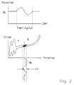
Das Gasspurenmeßsystem gemaß Fig. 1 besteht aus einem elektrochemischen Zwei- oder Dreielektrodensensor 1, einer Auswerteelektronik 2 mit einer Anzeige 3 und der Diagnoseschaltung 4, 5, 6. Die wesentlichen Komponenten der Diagnoseschaltung sind der Rechner 4, der Testspannungsgenerator 5 und der Alarmgeber 6. Der Sensor 1 erzeugt abhängig von der anstehenden Gaskonzentration ein Stromsignal, das von der analogen Auswerteelektronik verstärkt und vom Instrument 3 angezeigt wird. Außerdem sorgt die Auswerteelektronik 2 dafür, daß zwischen der Arbeitselektrode und der Gegenelektrode des Sensors 1 (bei einem Zweielektrodensensor) bzw. zwischen Arbeitselektrode und Referenzelektrode (bei einem Dreielektrodensensor) in Abhängigkeit von der zu messenden Gasart ein vorgegebenes Sollpotential U₀ eingestellt wird.1 consists of an electrochemical two- or three-
Wenn eine Funktionskontrolle des Sensors 1 durchgeführt werden soll, wird von der Diagnoseschaltung vom Meßmodus vorübergehend in einen Testmodus umgeschaltet. Im Testmodus wird dem Sollpotential U₀ an der Arbeitselektrode eine Testspannung ΔU überlagert. Die Testspannung ΔU kann entweder eine periodische Wechselspannung oder ein einmaliger Rechteckimpuls sein und wird von dem Testspannungsgenerator 5 geliefert. Die Umschaltung vom Meßmodus in den Testmodus erfolgt manuell, z.B. durch Betätigung eines Schalters, oder wird selbsttätig vom Rechner 4 in regelmäßigen Zeitabständen durchgeführt.If a functional check of the
Die Änderung des Arbeitselektrodenpotentials hat eine Änderung des Stromsignals zur Folge, die für Testzwecke ausgenutzt wird. Diese Stromantwort des Sensors oder eine davon durch weitere Meßwertverarbeitung abgeleitete Größe (nachfolgend näher erläutert) wird hier als Testsignal bezeichnet. Die durch die Testspannung hervorgerufenen. Testsignale können z.B. direkt mit vorgegebenen Sollwerten verglichen werden, die für die Sensorqualität spezifisch sind und vorher bei fehlerfrei funktionierenden Sensorzellen empirisch bestimmt wurden. Diese Sollwerte sind ebenfalls im Rechner 4 gespeichert. Der Rechner 4 vergleicht auch die Testsignale mit den vorgegebenen Sollwerten (Komparatorfunktion) und gibt bei einer unzulässigen Überschreitung einen Alarm aus (Alarmgeber 6). Ferner kann das Zeitverhalten des Sensors, insbesondere die Ansprechzeit, durch eine Registrierung der zeitlichen Änderung des Testsignals untersucht werden. Zu diesem Zweck wird dem Sollpotential an der Arbeitselektrode als Testspannung ein kurzer Rechteckimpuls überlagert und das dadurch hervorgerufene Testsignal als Funktion der Zeit registriert. Im folgenden werden Ausführungsbeispiele für einen Funktionstest bei einem Dreielektroden- und Zweielektrodensensor beschrieben.The change in the working electrode potential results in a change in the current signal, which is used for test purposes. This current response of the sensor or a variable derived therefrom by further measured value processing (explained in more detail below) is referred to here as a test signal. The caused by the test voltage. Test signals can, for example, be compared directly with predefined target values which are specific to the sensor quality and which were previously determined empirically in the case of sensor cells which function correctly. These setpoints are also stored in the
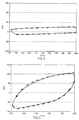
Mit einem potentiostatisch betriebenen Dreielektrodensensor wird für einen kurzen Testzyklus (typisch 1 bis 20 s) eine zyklische Voltametrie durchgeführt. Zu diesem Zweck wird das vorgegebene Sollpotential U₀ mit einer Sinuswechselspannung moduliert und das resultierende Stromsignal an der Arbeitselektrode gemessen. Die Amplitude ΔU der sinusförmigen Wechselspannung liegt im Bereich von 1 bis 200 mV, die Frequenz zwischen 0,01-10 s⁻¹, vorzugsweise 0,1-1 s⁻¹. In dem unteren Bild in Fig. 2 ist ein zyklisches Voltagramm (Kurve A) dargestellt, das man erhält, wenn das Arbeitselektrodenpotential (bezogen auf die Referenzelektrode) in einem weiten Bereich variiert wird und das zugehörige Stromsignal registriert wird. Ein solches zyklisches Voltagramm wird standardmäßig zur elektrochemischen Analyse von Katalysatoroberflächen und Elektrolyten herangezogen. Ein differentielles zyklisches Voltagramm (Kurve B) erhält man dagegen, wenn dem stationären Sollpotential U₀, wie oben beschrieben, eine Wechselspannung ΔU überlagert wird und die dazugehörende Stromsignaländerung an der Arbeitselektrode registriert wird. Von dem stationären Sollpotential U₀ ausgehend, wird so ein kleiner Ausschnitt des zyklischen Voltagramms mit der sich ergebenden Hysterese zwischen anodischem und kathodischem Durchlauf durchfahren (Kurve B). Die Hysterese entsteht durch den Aufbau bzw. den Abbau der Elektrodendeckschicht und ist von der Änderungsgeschwindigkeit des Potentials abhängig. Die Fläche dieser Hysteresekurve des differentiellen zyklischen Voltagramms, d.h. das Integral über die Differenz zwischen kathodischem und anodischem Durchlauf, liefert ein Kriterium für die Funktion des gesamten elektrochemischen Dreielektrodensensors. Aus diesem Grund wird hier die Hysteresefläche als Testsignal verwendet. Das Testsignal wird also hier im Rechner 4 durch Integration des in die Arbeitselektrode fließenden Stromsignals über eine Periode der Wechselspannung gebildet und mit vorgewählten Sollwerten verglichen.With a potentiostatically operated three-electrode sensor, a cyclic voltammetry is carried out for a short test cycle (typically 1 to 20 s). For this purpose, the predetermined target potential U₀ is modulated with an alternating sine voltage and the resulting current signal is measured at the working electrode. The amplitude ΔU of the sinusoidal AC voltage is in the range from 1 to 200 mV, the frequency between 0.01-10 s⁻¹, preferably 0.1-1 s⁻¹. The lower picture in FIG. 2 shows a cyclic voltagram (curve A) which is obtained when the working electrode potential (based on the reference electrode) is varied over a wide range and the associated current signal is registered. Such a cyclic voltagram is used as standard for the electrochemical analysis of catalyst surfaces and electrolytes. A differential cyclic voltagram (curve B), on the other hand, is obtained if an alternating voltage ΔU is superimposed on the stationary target potential U₀, as described above, and the associated change in current signal is registered at the working electrode. Starting from the stationary set potential U₀, a small section of the cyclic voltagram with the resulting hysteresis between anodic and cathodic passage is traversed (curve B). The hysteresis arises from the buildup or breakdown of the electrode cover layer and is dependent on the rate of change of the potential. The area of this differential cyclic voltagram hysteresis curve, i.e. the integral over the difference between cathodic and anodic passage provides a criterion for the function of the entire electrochemical three-electrode sensor. For this reason, the hysteresis area is used here as a test signal. The test signal is thus formed here in the
Fig. 3 zeigt ein experimentell registriertes, differentielles zyklisches Voltagramm einer defekten und Fig. 4 einer intakten Sensorzelle, die mit dem hier beschriebenen Testverfahren verglichen wurden. Die aufgenommenen Hysteresekurven bei einer Modulation der Arbeitspotentiale von 150 mV mit einer Wechselspannung von 50 mV zeigen einen deutlichen Unterschied zwischen den beiden Sensoren. Die ca. um den Faktor 5 unterschiedlichen Hystereseflächen ermöglichen eine klare Erkennung der defekten Zelle. Die Form und die Fläche der Hysteresekurve sind unabhängig von der Begasung der Zelle, so daß der Funktionstest auch direkt während einer Messung bei Begasung durchgeführt werden kann.FIG. 3 shows an experimentally registered, differential cyclic voltagram of a defective and FIG. 4 an intact sensor cell, which were compared with the test method described here. The recorded hysteresis curves with a modulation of the working potential of 150 mV with a AC voltage of 50 mV show a clear difference between the two sensors. The hysteresis areas, which differ by a factor of around 5, enable the defective cell to be clearly identified. The shape and area of the hysteresis curve are independent of the fumigation of the cell, so that the function test can also be carried out directly during a fumigation measurement.
Ein Bruch einer der Elektrodenableitungen, Eintrocknen oder Auslaufen des Elektrolyten, fehlende Benetzung einer der Elektroden, Vergiftung der Katalysatoren und andere Fehler machen sich durch eine signifikante Veränderung der Hysteresefläche bemerkbar und können daher als Fehlfunktion erkannt werden und in ein Alarmsignal oder eine Fehlermeldung umgesetzt werden. Durch den kurzen Testzyklus wird praktisch die kontinuierliche Überwachung einer Gaskonzentration nicht gestört. Im übrigen kann der Testzyklus zusätzlich durch eine Speicherung des letzten Meßwertes überbrückt werden. In extrem zeitkritischen Fällen können zwei identische Zellen parallel betrieben werden, wobei der Funktionstest im Wechseltakt erfolgt und jeweils ein Sensor getestet wird, während der andere in den Meßmodus geschaltet ist und den kontinuierlichen Meßbetrieb sicherstellt.A break in one of the electrode leads, drying or leakage of the electrolyte, lack of wetting of one of the electrodes, poisoning of the catalysts and other errors are noticeable by a significant change in the hysteresis area and can therefore be recognized as a malfunction and converted into an alarm signal or an error message. The short test cycle practically does not disturb the continuous monitoring of a gas concentration. The test cycle can also be bridged by storing the last measured value. In extremely time-critical cases, two identical cells can be operated in parallel, the function test being carried out in alternating cycles and one sensor being tested, while the other is switched to the measurement mode and ensuring continuous measurement operation.
Das Sensormeßsignal ist in diesem Fall der bei einem voreingestellten Arbeitselektrodenpotential (U₀) amperometrisch gemessene Strom. Diesem Sollpotential wird mit Hilfe des Testspannungsgenerators 5 kurzzeitig ein Rechteckimpuls mit einer Dauer von 1 ms bis 100 ms und einer Amplitude von 1 bis 200 mV überlagert. Als Testspannung wird also hier keine periodische Wechselspannung, sondern ein einmaliger Spannungsimpuls verwendet. Dieser Spannungsimpuls hat eine charakteristische Stromantwort zur Folge, die hier als Testsignal benutzt wird und eine Information über die Funktionstüchtigkeit des Sensors liefert. Auch bei diesem Test werden Defekte der Sensorzelle als signifikante Änderung der Stromantwort erkannt.In this case, the sensor measurement signal is the current measured amperometrically at a preset working electrode potential (U₀). With the help of the
Die beschriebenen Testfunktionen, wie Umschaltung in den Testmodus, Zuschaltung des Testspannungsgenerators 5, Integration und Differentiation der Signalspannungen, Vergleich mit Standardwerten, Alarmauslösung, können natürlich auch mit diskreten elektrischen Bauelementen oder Baugruppen realisiert werden. Die Diagnoseschaltung kann aber dann nicht so raumsparend aufgebaut werden wie bei Verwendung eines Mikroprozessors.The test functions described, such as switching to the test mode, switching on the
Claims (6)
Applications Claiming Priority (2)
| Application Number | Priority Date | Filing Date | Title |
|---|---|---|---|
| DE4318891 | 1993-06-07 | ||
| DE19934318891 DE4318891A1 (en) | 1993-06-07 | 1993-06-07 | Electrochemical gas trace measuring system with function control |
Publications (2)
| Publication Number | Publication Date |
|---|---|
| EP0628810A2 true EP0628810A2 (en) | 1994-12-14 |
| EP0628810A3 EP0628810A3 (en) | 1995-11-15 |
Family
ID=6489813
Family Applications (1)
| Application Number | Title | Priority Date | Filing Date |
|---|---|---|---|
| EP94250126A Withdrawn EP0628810A3 (en) | 1993-06-07 | 1994-05-16 | Electrochemical analyser for gas traces with functioning check. |
Country Status (2)
| Country | Link |
|---|---|
| EP (1) | EP0628810A3 (en) |
| DE (1) | DE4318891A1 (en) |
Cited By (6)
| Publication number | Priority date | Publication date | Assignee | Title |
|---|---|---|---|---|
| US8877035B2 (en) | 2005-07-20 | 2014-11-04 | Bayer Healthcare Llc | Gated amperometry methods |
| WO2017136407A1 (en) * | 2016-02-02 | 2017-08-10 | Msa Technology, Llc | Sensor interrogation with fast recovery |
| US9835582B2 (en) | 2005-09-30 | 2017-12-05 | Ascensia Diabetes Care Holdings Ag | Devices using gated voltammetry methods |
| US9933385B2 (en) | 2007-12-10 | 2018-04-03 | Ascensia Diabetes Care Holdings Ag | Method of using an electrochemical test sensor |
| US10067082B2 (en) | 2004-02-06 | 2018-09-04 | Ascensia Diabetes Care Holdings Ag | Biosensor for determining an analyte concentration |
| US10190150B2 (en) | 2006-10-24 | 2019-01-29 | Ascensia Diabetes Care Holdings Ag | Determining analyte concentration from variant concentration distribution in measurable species |
Families Citing this family (10)
| Publication number | Priority date | Publication date | Assignee | Title |
|---|---|---|---|---|
| DE29504089U1 (en) * | 1995-03-10 | 1996-04-11 | Palocz Andresen Michael Dr Ing | Continuous measurement of the odorant concentration in gas pressure control stations using an odorant detector |
| DE19510574C1 (en) * | 1995-03-23 | 1996-06-05 | Testo Gmbh & Co | Condition monitoring system for amperometric electrochemical gas sensor |
| DE19628539A1 (en) * | 1996-07-16 | 1998-03-12 | Csb Syst Software Entwicklung | Arrangement and method for quality assurance of electronic measuring devices |
| DE69631142T2 (en) * | 1996-10-29 | 2004-06-03 | Zellweger Analytics Ltd., Poole | Condition monitoring of a gas detector |
| DE19734860C2 (en) * | 1997-08-12 | 1999-12-16 | Bosch Gmbh Robert | Method for the determination of oxidisable components in a gas mixture |
| DE19743979A1 (en) * | 1997-10-06 | 1999-04-08 | Conducta Endress & Hauser | Operation of electrochemical sensor, especially an amperometric gas sensor |
| FR2798996A1 (en) * | 1999-09-23 | 2001-03-30 | Suisse Electronique Microtech | SELF-DIAGNOSTIC ELECTROCHEMICAL SENSOR |
| DE10260046B4 (en) * | 2002-12-19 | 2004-11-25 | Gerald Scharrer | Method for checking the reactivity of an electronic sensor and device for carrying out the method |
| GB201420982D0 (en) | 2014-11-26 | 2015-01-07 | Inside Biometrics Ltd | Verifying operation of a meter |
| DE102015016742B4 (en) * | 2015-12-24 | 2018-11-29 | Gerald Scharrer | Method for checking the reactivity of an electrical and / or electronic sensor |
Citations (3)
| Publication number | Priority date | Publication date | Assignee | Title |
|---|---|---|---|---|
| DE3136248A1 (en) * | 1980-09-18 | 1982-08-05 | List, Hans, Prof. Dipl.-Ing. Dr.Dr.h.c., 8020 Graz | METHOD FOR CHECKING THE CONDITION OF POLAROGRAPHIC MEASURING ELECTRODES AND DEVICE FOR CARRYING OUT THE METHOD |
| US4705617A (en) * | 1983-05-06 | 1987-11-10 | Sensormedics Corporation | Apparatus for deplating cutaneous gas sensors |
| WO1990012315A1 (en) * | 1989-04-04 | 1990-10-18 | Neotronics Limited | Fault detection in electrochemical gas sensing equipment |
Family Cites Families (7)
| Publication number | Priority date | Publication date | Assignee | Title |
|---|---|---|---|---|
| US4077861A (en) * | 1976-01-28 | 1978-03-07 | Teledyne Industries, Inc. | Polarographic sensor |
| US4189367A (en) * | 1978-10-19 | 1980-02-19 | Leeds & Northrup Company | Method for testing ion selective electrodes in continuous measuring systems |
| FI78990C (en) * | 1984-10-30 | 1989-10-10 | Outokumpu Oy | FOERFARANDE FOER MAETNING OCH REGLERING AV DEN ELEKTROKEMISKA POTENTIALEN OCH / ELLER KOMPONENTHALTEN I EN BEHANDLINGSPROCESS AV VAERDEMATERIAL. |
| DE3668991D1 (en) * | 1986-04-15 | 1990-03-15 | Yokagawa Electrofact B V | DEVICE FOR TESTING THE COMPLETENESS OF AN ELECTRODE IN A POTENTIOMETRIC ELECTRODESYSTEM. |
| DE3705901C2 (en) * | 1987-02-24 | 1996-12-12 | Siemens Ag | Pressure transducer |
| JPH03134552A (en) * | 1989-10-20 | 1991-06-07 | Hitachi Ltd | Detecting apparatus with self-calibration function |
| JP2788511B2 (en) * | 1989-11-15 | 1998-08-20 | 日本碍子株式会社 | Processing method of oxygen concentration detector |
-
1993
- 1993-06-07 DE DE19934318891 patent/DE4318891A1/en not_active Withdrawn
-
1994
- 1994-05-16 EP EP94250126A patent/EP0628810A3/en not_active Withdrawn
Patent Citations (3)
| Publication number | Priority date | Publication date | Assignee | Title |
|---|---|---|---|---|
| DE3136248A1 (en) * | 1980-09-18 | 1982-08-05 | List, Hans, Prof. Dipl.-Ing. Dr.Dr.h.c., 8020 Graz | METHOD FOR CHECKING THE CONDITION OF POLAROGRAPHIC MEASURING ELECTRODES AND DEVICE FOR CARRYING OUT THE METHOD |
| US4705617A (en) * | 1983-05-06 | 1987-11-10 | Sensormedics Corporation | Apparatus for deplating cutaneous gas sensors |
| WO1990012315A1 (en) * | 1989-04-04 | 1990-10-18 | Neotronics Limited | Fault detection in electrochemical gas sensing equipment |
Cited By (14)
| Publication number | Priority date | Publication date | Assignee | Title |
|---|---|---|---|---|
| US10067082B2 (en) | 2004-02-06 | 2018-09-04 | Ascensia Diabetes Care Holdings Ag | Biosensor for determining an analyte concentration |
| US8877035B2 (en) | 2005-07-20 | 2014-11-04 | Bayer Healthcare Llc | Gated amperometry methods |
| US10670553B2 (en) | 2005-09-30 | 2020-06-02 | Ascensia Diabetes Care Holdings Ag | Devices using gated voltammetry methods |
| US11435312B2 (en) | 2005-09-30 | 2022-09-06 | Ascensia Diabetes Care Holdings Ag | Devices using gated voltammetry methods |
| US9835582B2 (en) | 2005-09-30 | 2017-12-05 | Ascensia Diabetes Care Holdings Ag | Devices using gated voltammetry methods |
| US11091790B2 (en) | 2006-10-24 | 2021-08-17 | Ascensia Diabetes Care Holdings Ag | Determining analyte concentration from variant concentration distribution in measurable species |
| US10190150B2 (en) | 2006-10-24 | 2019-01-29 | Ascensia Diabetes Care Holdings Ag | Determining analyte concentration from variant concentration distribution in measurable species |
| US9933385B2 (en) | 2007-12-10 | 2018-04-03 | Ascensia Diabetes Care Holdings Ag | Method of using an electrochemical test sensor |
| US10690614B2 (en) | 2007-12-10 | 2020-06-23 | Ascensia Diabetes Care Holdings Ag | Method of using an electrochemical test sensor |
| US10234417B2 (en) | 2016-02-02 | 2019-03-19 | Msa Technology, Llc | Sensor interrogation with fast recovery |
| AU2017214406B2 (en) * | 2016-02-02 | 2020-07-30 | Msa Technology, Llc | Sensor interrogation with fast recovery |
| CN108369206A (en) * | 2016-02-02 | 2018-08-03 | Msa技术有限公司 | Sensor interrogation with fast quick-recovery |
| WO2017136407A1 (en) * | 2016-02-02 | 2017-08-10 | Msa Technology, Llc | Sensor interrogation with fast recovery |
| EP4249909A3 (en) * | 2016-02-02 | 2023-11-22 | MSA Technology, LLC | Sensor interrogation with fast recovery |
Also Published As
| Publication number | Publication date |
|---|---|
| EP0628810A3 (en) | 1995-11-15 |
| DE4318891A1 (en) | 1994-12-08 |
Similar Documents
| Publication | Publication Date | Title |
|---|---|---|
| EP0628810A2 (en) | Electrochemical analyser for gas traces with functioning check | |
| DE10362049B9 (en) | In-operation test of a signal path | |
| DE19716520B4 (en) | Formed as a circuit device for detecting operating variables of electric motors and electric motor | |
| DE10062062C1 (en) | Electrochemical sensor used e.g. in control technology has a microprocessor integrated on chip of an electronic device for receiving and further processing signals from the device | |
| EP3265754B1 (en) | Measuring bridge arrangement with improved error detection | |
| DE3844386C2 (en) | ||
| DE3809107C2 (en) | ||
| DE4439584A1 (en) | Transient method for determining solution resistance for simple and accurate measurement of corrosion rate | |
| DE4231128C2 (en) | Limiting current oxygen concentration | |
| EP0497994B1 (en) | Method and circuit for monitoring an ion- or redox-potential measuring electrode system | |
| WO2004090524A1 (en) | Device for operating a gas sensor | |
| EP1143239A1 (en) | Method for monitoring the quality of electrochemical measuring sensors and measuring device with an electrochemical sensor | |
| EP0419769A2 (en) | Method for continuously monitoring an electrode system for potentiometric measurements | |
| DE19820207A1 (en) | Antenna test arrangement for vehicle control system | |
| DE19625896A1 (en) | Warning of impending failure in auto-calibration system of e.g. gas analysis instruments | |
| EP0635135B1 (en) | Method of monitoring rpm sensors | |
| DE102009029073B4 (en) | Method for carrying out a self-test for a micromechanical sensor device and corresponding micromechanical sensor device | |
| DE19536315A1 (en) | Method for monitoring automated pH measurements | |
| EP1002223B1 (en) | Method and device for determining the time curve of the intensity of radiation in a weathering testing device | |
| DE102017113474A1 (en) | Device for monitoring the remaining life of device systems, devices or subcomponents of devices | |
| DE3813269A1 (en) | NETWORK MONITORING CIRCUIT | |
| DE102018124092A1 (en) | Electronic circuit for an electrochemical sensor and method for functional analysis of the electrochemical sensor | |
| EP0479033A2 (en) | Method for the determination of the concentration of electrochemically convertible gases | |
| WO2022083998A1 (en) | Error analysis in a sensor | |
| DE102019123163A1 (en) | MEASURING DEVICE AND CALIBRATION METHOD |
Legal Events
| Date | Code | Title | Description |
|---|---|---|---|
| PUAI | Public reference made under article 153(3) epc to a published international application that has entered the european phase |
Free format text: ORIGINAL CODE: 0009012 |
|
| AK | Designated contracting states |
Kind code of ref document: A2 Designated state(s): DE ES FR GB IT NL |
|
| PUAL | Search report despatched |
Free format text: ORIGINAL CODE: 0009013 |
|
| RAP1 | Party data changed (applicant data changed or rights of an application transferred) |
Owner name: COMPUR MONITORS SENSOR TECHNOLOGY GMBH |
|
| AK | Designated contracting states |
Kind code of ref document: A3 Designated state(s): DE ES FR GB IT NL |
|
| STAA | Information on the status of an ep patent application or granted ep patent |
Free format text: STATUS: THE APPLICATION IS DEEMED TO BE WITHDRAWN |
|
| 18D | Application deemed to be withdrawn |
Effective date: 19960517 |