EP0629082A1 - Spatial correction method of digital images - Google Patents
Spatial correction method of digital images Download PDFInfo
- Publication number
- EP0629082A1 EP0629082A1 EP94401070A EP94401070A EP0629082A1 EP 0629082 A1 EP0629082 A1 EP 0629082A1 EP 94401070 A EP94401070 A EP 94401070A EP 94401070 A EP94401070 A EP 94401070A EP 0629082 A1 EP0629082 A1 EP 0629082A1
- Authority
- EP
- European Patent Office
- Prior art keywords
- row
- rows
- pixels
- offset
- image
- Prior art date
- Legal status (The legal status is an assumption and is not a legal conclusion. Google has not performed a legal analysis and makes no representation as to the accuracy of the status listed.)
- Granted
Links
Images


Classifications
-
- G—PHYSICS
- G06—COMPUTING; CALCULATING OR COUNTING
- G06T—IMAGE DATA PROCESSING OR GENERATION, IN GENERAL
- G06T7/00—Image analysis
- G06T7/20—Analysis of motion
-
- H—ELECTRICITY
- H04—ELECTRIC COMMUNICATION TECHNIQUE
- H04N—PICTORIAL COMMUNICATION, e.g. TELEVISION
- H04N23/00—Cameras or camera modules comprising electronic image sensors; Control thereof
- H04N23/60—Control of cameras or camera modules
- H04N23/68—Control of cameras or camera modules for stable pick-up of the scene, e.g. compensating for camera body vibrations
- H04N23/681—Motion detection
- H04N23/6811—Motion detection based on the image signal
-
- H—ELECTRICITY
- H04—ELECTRIC COMMUNICATION TECHNIQUE
- H04N—PICTORIAL COMMUNICATION, e.g. TELEVISION
- H04N23/00—Cameras or camera modules comprising electronic image sensors; Control thereof
- H04N23/60—Control of cameras or camera modules
- H04N23/68—Control of cameras or camera modules for stable pick-up of the scene, e.g. compensating for camera body vibrations
- H04N23/682—Vibration or motion blur correction
Definitions
- the present invention relates generally to digital image processing in order to improve the visual appearance of images and thus facilitate their subsequent exploitation.
- the invention relates more particularly to a method of spatial correction of digital images captured by devices on board mobile vehicles such as planes or ships.
- a device "photographs" an image line by line and reconstructs the image by juxtaposing the lines.
- the mobile machine undergoes during its movement disturbing movements such as roll or drift (yaw) which cause distortions of the image.
- an angular speed measuring gyrometer can be associated with the device so as to measure in real time the angle of the disturbing movements relative to the trajectory of the device and to correct the image distortion accordingly.
- the on-board device can be placed on a stabilized platform which corrects any disturbing movement. The on-board device then no longer undergoes disturbing movement.
- correction materials such as an angular speed measuring gyrometer or a stabilized platform
- jitter a synchronization signal
- the present invention aims to provide a spatial digital image processing method which improves the visual appearance of an image economically, by correcting not only image distortions due to disturbing movements, but also distortions due to synchronization faults.
- a method of spatial digital image correction composed of a set of rows of pixels which are rows or columns of the image, is characterized in that it comprises comparing the rows two by two to determine the first offsets between rows expressed as a whole number of pixels, determining second offsets between rows expressed as a non-integer number of pixels, as a function of the first offsets, the determination for each row of a third offset of said row relative to a reference row as a function of the second offsets, and the correction of each row by an offset of the pixels of said each row relative to the reference row equal to the whole part of the third offset for said each row, and by a spatial smoothing of pixels of said each row with smoothing coefficients function of the third offset for said each row.
- the comparison of the rows two by two comprises, for two given rows, the calculation of correlation sums between the two rows offset respectively when one is subjected with respect to the other to predetermined shifts expressed in whole number of pixels, the search for a minimum correlation sum among the correlation sums calculated in order to deduce therefrom said first offset between the two rows expressed in whole number of pixels.
- a sum of correlation between two rows offset by an offset expressed as an integer of pixels is equal to the sum of the absolute values of the differences of the values of the pixels of one row and of the values of the pixels offset from said offset of the other row.
- the determination of the second offset between two rows expressed as a non-integer number of pixels is refined by an interpolation of the correlation sums as a function of the predetermined offsets between the two rows, by a polynomial function of order greater than or equal to 2 around the first offset, the second offset being the abscissa of a minimum of the interpolation function.
- the polynomial function may be a parabolic function whose vertex constitutes said minimum.
- the determination for a given row of a third offset of said row relative to a reference row is carried out by the sum of the second offsets of the rows included between the reference row and the given row.
- the spatial smoothing coefficients of a row are such that their sum is equal to 1.
- the spatial smoothing coefficients of a row are such that a first coefficient is equal to the decimal part of the third shift in the row and a second coefficient is equal to or complementary to 1 of the first coefficient.
- the second offsets between rows are replaced by offsets corrected as a function of the second offsets and such that their average value is zero.
- This step is based on the distinction between the offsets to be corrected due to disturbances such as roll and "natural offsets" in the image, such as a road or a watercourse not parallel to the trajectory of the craft. .
- the second offsets between rows are replaced by corrected offsets respectively equal to the average of the second offsets.
- a shooting means 2 is fixed essentially comprising a detection means preferably sensitive to infrared, a single-line analyzer and a means memory and / or data transmission means.
- a line L is an "elementary band" of band 3, transverse to band 3, and the juxtaposition of a set of successive lines forms an image of a portion of band 3, the movement of the aircraft along the strip providing image scanning (frame).
- a line picked up by the detection means undergoes an analog / digital conversion at the input of the analyzer.
- a line is a set of M pixels and a group of N lines is a matrix of N x M pixels, forming a digital image with N rows and M columns.
- a line or a column of the image constitutes a row of pixels in the matrix, and by extension a row of the image within the meaning of the present invention.
- a digital line is memorized by the memory means.
- the brightness levels of the pixels of the line are transmitted by the transmission means to a receiver associated with a storage and data processing means.
- the term "brightness" refers to the luminance for a black and white image, or to one of the primary red, green and blue components or to one of the luminance and chrominance signals for a color image.
- the shooting device and in particular the optical detection means are fixed relative to the aircraft.
- the aircraft preferably flies in a straight line and at constant altitude.
- the aircraft undergoes during the flight disturbing movements in particular of roll, that is to say small alternating rotations R around the longitudinal axis of the aircraft, and of drift, that is to say a rotation D around a vertical axis, or yaw, that is to say small alternating rotations around a vertical axis.
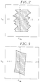
- Figure 2 is shown schematically an image disturbed only by the roll of the aircraft.
- the actual geometric shape of the scene on the portion of strip of land photographed is a dark rectangle, on a light background.
- the image provided by the analyzer on board the rolled aircraft has a deformed geometric shape.
- the image is composed of N rows L1 to L N and M columns C1 to C M , of which a row L n and a column C m are shown by way of example, with 1 ⁇ n ⁇ N and 1 ⁇ m ⁇ M.
- Roll causes image distortion in the line direction, that is, the lines are offset from each other.
- an image comprises for example 1024 rows and 1024 columns.
- a schematic image is disturbed only by drifts of the aircraft mainly in the same direction relative to the trajectory of the aircraft.
- the actual geometric shape is again a dark rectangle on a light background.
- the image provided by the analyzer on board the aircraft subject to drift has a deformed geometric shape resulting from the transformation of the original rectangle substantially into a diamond.
- a row L n among N rows and a column C m among M columns are also represented in FIG. 3.
- the drift causes a deformation in the column direction, that is to say the columns are offset with respect to each other .
- the deformations due to roll and the deformations due to the drift combine randomly.
- these two types of deformation make it difficult for an operator to read and interpret the images.
- other distortions alter an image.
- the data is synchronized by a threshold reference on a rising edge of a synchronization signal.
- the rising edge is noisy, the position of the threshold on the rising edge undergoes variations causing a jitter phenomenon, that is to say instability in the direction of the lines of the image. This instability causes shifts between lines similar to the deformations due to roll, but of lower amplitude.
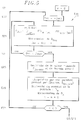
- an image correction method for more particularly to a deformed image of the roll is illustrated as an algorithm consisting of five main steps E10 to E50 and programmed in a computer memory. Image correction is performed in the aircraft, or alternatively on the ground. In all cases, as has already been specified, an image is a matrix of N x M pixels stored.
- the method comprises a first step E10 of reading an image which consists in reading the brightness levels of the N ⁇ M pixels of the image with N rows and M columns in an image memory.
- Step E20 determines and stores the offsets of the lines taken two by two successively.
- Step E20 is composed of a set of steps E21 to E27 which will be described in detail with reference to FIG. 5.
- Step E30 treats the offsets between lines to separate the offsets due to the roll, from any offset not related to the shooting, but actually existing on the portion of land photographed, for example a road forming an angle with the edges of the image, or a meandering stream.
- Step E30 is composed of a set of steps E31 to E34 which will be described in detail with reference to FIG. 6.
- Step E40 determines the corrected image from the offsets between lines determined in step E30. As a variant, step E40 determines the corrected image from the offsets between lines determined at step E20; this variant does not include step E30.
- step E40 consists of a set of steps E41 to E46 which will be described in detail with reference to FIG. 7.
- the new image corrected for the effects of roll is stored in step E50, and is preferably also displayed on the screen of a display console associated with the computer.
- the image corrected in step E40 can be processed again from step E10.
- Several successive correction cycles improve the image more than a single cycle.
- the number of correction cycles is either fixed, determined once and for all, for example equal to 1, 2 or 3, or chosen by the operator, or again determined dynamically by the algorithm on an image quality criterion corrected.
- the determination of the offsets between lines comprises a set of steps E21 to E27. Any line L n of the image is compared with the adjacent line L n-1 previously stored. Step E21 initializes the determination on line L2 which is compared with line L1.
- the line L1 is not affected by the image correction and is a reference line.
- the reference line is the line L N and the comparison then begins with the line L N-1 , which is compared with the line L N.
- the reference line is any line in the image.
- Step E22 initializes an integer shift of pixel Dec to a value -Dmin.
- Lag Dec is the comparison offset from line L n with line L n-1 .
- step E24 the offset Dec is compared with a predetermined value Dmax which is the maximum value of the offset Dec. If the value of the offset Dec is less than or equal to the value Dmax, step E23 is again carried out. Otherwise, all the correlation sums S Dec for Dec varying from -Dmin to Dmax are determined, i.e. sums by number of (Dmin + Dmax + 1), and the algorithm goes to step E25.
- the variation limits -Dmin and Dmax of the offset Dec are for example -25 and +25 pixels.
- Step E25 searches for the minimum sum S Decmin among the sums determined previously, as well as the associated Decmin offset.
- the minimum sum S Decmin is the first sum found of which the two adjacent sums preceding and following are greater than it when Dec increases from - Dmin to Dmax.
- all the sums S Dec are analyzed, by comparing the sums two by two, and keeping as the result of each comparison the lowest sum S Dec.
- the minimum sum S Decmin is the first sum found of which the two adjacent sums preceding and following it are greater by difference values greater than a predetermined threshold.
- Step E26 determines the offset D n of the line L n with respect to the line L n-1 , with an accuracy less than the pixel; in general, D n is a non-integer number of pixels.
- the shift D n is determined as a function of the shifts Decmin, (Decmin-1) and (Decmin + 1) as well as the correlation sums associated with each of these shifts D Decmin , S Decmin-1 and S Decmin + 1 . In a coordinate system having the offsets for abscissa x and the correlation sums for ordinates y, these three pairs of offset and sum define three points.
- the offset D n can be determined as the abscissa of the minimum of the parabola passing through the three points (Decmin, S Decmin ), (Decmin + k, S Decmin + k ), (Decmin-k, S Decmin- k ) where k is an integer, for example 2 or 3.
- the parabola is replaced by a polynomial function of a higher order than two.
- Step E27 compares the value of n with the total number of lines N. If n is less than or equal at N, there remains at least one line for which the offset D n has not been determined and the calculation resumes for a new line from step E22. Otherwise, all the offsets D2 to D N are determined and the algorithm goes to step E31 which is described below.
- any line L n is not compared to the adjacent line L n-1 , but to the line L ni , where i is an integer greater than 1, then the parameter n is incremented by i.
- the integer i is worth 2 and only the rows of even rank are treated.
- the lines of odd rank are offset (step E40) by an offset equal to the offset calculated for the line of previous even rank. The number of calculations is reduced and the execution speed is increased.
- the processing of offsets between lines comprises four main steps E31 to E34.
- the purpose of this processing is to correct the values of the shifts D n , for n varying from 2 to N, determined in step E26.
- the offsets D n depend on the offsets due to rolling, but also on "offsets" represented by inclined or broken lines and actually existing on the strip of land considered, for example a road not parallel to the edges of the strip of land .
- the correction of the offsets is based on the observation that the variations in the orientation of the aircraft relative to its trajectory due to the roll are statistically zero.
- the roll offsets are zero on average over a large number of lines, 1024 for example, while the "real offsets" on the ground are not a priori zero on average.
- the correction results in corrected offset values, the mean of which is zero.
- the correction is first order on the offsets; alternatively, the correction is of a higher order.
- the correction of the offsets is such that a predetermined set of lines of the image is not modified during the determination of the corrected image, which will be described in detail below.
- this predetermined set of lines comprises the lines L1, L N / 2 and L N.
- the set includes a larger number of lines, for example 4.5 or 6, which are evenly distributed or not in the image.
- the number and / or the position in the image of the lines of this set are chosen by the operator.
- Step E31 determines three coefficients S1, S2 and P used for the correction of the offsets.
- the coefficient S1 is the sum of all the shifts D n , for 2 ⁇ n ⁇ N.
- the coefficient S2 is the sum of the shifts D n , for 2 ⁇ n ⁇ N / 2, that is to say for the half-image between the lines L1 and L N / 2 .
- the coefficient P represents a coefficient equal to 4 (S1-2S2) / N2 relating to the variation of the offset of the lines with respect to the first reference line between the limit lines L1 and L N / 2 , and L N / 2 and L N.
- Step E32 initializes the determination of the offset correction on the second line since, as already specified, the first line of the image is not modified during the determination of the corrected image.
- Step E33 calculates a correction coefficient Cor n , which is equal to S1 / N + P x (n - N / 2) in order to reduce the variation in the offset of the lines relative to the first reference line along a right.
- the coefficient Cor n is then subtracted from the offset D n , which produces a corrected offset Dc n .
- the parameter n is incremented by 1.
- Step E34 compares the parameter n with the value N; if n is less than or equal to N, step E33 is again carried out for this new value of n. Otherwise, all the corrected offsets Dc n , for 2 ⁇ n ⁇ N, are determined and the algorithm goes to step E41 which is detailed below.
- the determination of the corrected image comprises a set of steps E41 to E46 and is carried out line by line.
- Step E41 initializes the correction of the image to the second line L2 of the image.
- a shift Decal n of the line L n is determined which is equal to the sum of the shifts Dc i , for 2 ⁇ i ⁇ n, and which defines the shift of the line L n with respect to the line of reference L1.
- Decal n is the sum of the shifts D i for 2 ⁇ i ⁇ n, calculated in step E26.
- the offset Decal n is generally a non-integer, the whole part of which is denoted En.
- the decimal part of Decal n is noted k n1 and the complement to 1 of k n1 is noted k n2 .
- Step E43 initializes at 1 a parameter m, representative of the rank of a pixel in the line L n .
- Step E44 determines the corrected luminance level Pc n, m of the pixel of rank m in the line L n by a pixel shift equal to the integer part of Decal n then by a spatial smoothing of pixel values of the line. Smoothing results from the contribution of two adjacent recorded pixels of rows m + En and m + En + 1 in the corrected pixel.
- the corrected level Pc n, m is thus the sum of the levels of pixel PIX n, m + En and PIX n, m + En + 1 respectively weighted by the coefficients k n1 and k n2 .
- the corrected level Pc n, m is memorized and the parameter m is incremented by 1.
- the coefficients k n1 and k n2 are determined differently, and are for example equal to 0 and 1 respectively, or to 0.5 and 0 , 5.
- the corrected level Pc n, m is a weighted sum of more than two pixel levels, for example PIX n, m + En-1 , PIX n, m + En and PIX n, m + En + 1 .
- the weighting coefficients are preferably such that their sum is equal to 1, so that there is no change in the average value of the pixels of the line.
- Step E45 checks whether the parameter m is less than or equal to the number M of the image column and therefore to the number of pixels in the row L n . If m is less than or equal to M, at least one pixel remains whose corrected value has not been determined, and step E44 is again traversed. When all the pixels of the line L n are corrected, then the parameter n is incremented by 1 to go to the next line. Step E46 checks whether the parameter n is less than or equal to N. In the event of a positive response, the algorithm proceeds with steps E42 to E45 for a new line. When all the lines are corrected, the algorithm proceeds to step E50 of memorizing the corrected image. As has already been said, as a variant, the main steps E10 to E40 can be carried out several times sequentially before proceeding to step E50.
- an image distortion correction method due to drift is illustrated as an algorithm consisting of five main steps E100 to E500, analogous to the steps E10 to E50 previously described with reference to Figure 4.
- the main difference is that the image correction is done column by column, not line by line.
- N ⁇ M pixel brightness levels stored from an image with N rows and M columns are read.
- Step E200 determines and stores the offsets of the columns taken two by two successively.
- Step E200 is composed of a set of steps E210 to E270 which will be described in detail with reference to FIG. 9.
- Step E300 processes the offsets between columns to separate the offsets due to drift from any offset not related to the shooting, but actually existing on the strip of land photographed.
- Step E300 is composed of a set of steps E310 to E340 which will be described in detail with reference to FIG. 10.
- Step E400 determines the corrected image from the offsets between columns determined in step E300.
- step E400 determines the corrected image from the offsets between columns determined in step E200; this variant does not include step E300.
- step E400 consists of a set of steps E410 to E460 which will be described in detail with reference to FIG. 11.
- the new image corrected for the effects of the drift is stored in step E500 and is preferably also displayed on the screen of a display console associated with the computer.
- step E400 the image corrected in step E400 can be processed again from step E100.
- the determination of the offsets between columns comprises the steps E210 to E270, which are respectively analogous to the steps E21 to E27 described with reference to FIG. 5, with the difference that the offsets are not determined row by row, but column by column.
- the letter "C” is added to the names of the different parameters.
- the columns are compared two by two to determine a first offset DecCmin of the column C m relative to the column C m-1 , expressed in whole number of pixels, then a second offset DC m of the column C m relative to the column C m-1 expressed as a non-integer number of pixels.
- the algorithm goes to step E310.
- the processing of the offsets between columns comprises four steps E310 to E340.
- the purpose of this processing is to correct the values of the DC m offsets, for 2 ⁇ m ⁇ M, determined in step E260.
- Step E310 includes the calculation of the sum SC and the mean MC of the shifts DC m , for 2 ⁇ m ⁇ M.
- Step E320 initializes the parameter m to 2 and step E330 determines the corrected offset DCc m of the column C m , which is equal to the mean MC of the offsets DC m .
- the parameter m is incremented by 1 to go to the next column.
- step E340 if m is less than or equal to M, step E330 is again carried out for this value of m; otherwise, the algorithm proceeds to the next step E340.
- the calculation of the sum SC and of the average MC of the shifts DC m is replaced by the calculation of a set of sums and averages calculated on groups of offset values.
- the corrected offset DCc m is then equal either to SC1, or to SC2, or to SC3 depending on whether m is between 2 and m1, or m1 + 1 and m2, or m2 + 1 and M.
- the algorithm does not include the steps E310 to E340 previously described. In this case, the algorithm goes directly from step E270 to step E410.
- the determination of the corrected image comprises the steps E410 to E460, respectively analogous to the steps E41 to E46 described with reference to FIG. 7.
- the determination of the corrected image is not carried out line by row, but column by column.
- the corrected brightness levels of pixel PC n, m are determined , for 1 ⁇ n ⁇ N, each according to the levels recorded or calculated in step E42 PIX n + ECm, m and PIX n + ECm +1, m of two adjacent pixels in the same column.
- the algorithm proceeds to step E500 of memorizing the corrected image.
- the two types of image correction respectively according to steps E10 to E40 and E100 to E400 are for example carried out sequentially on an image, in this order or the reverse order, or else an operator chooses to carry out only one of the two types of correction for a given image.
Abstract
Description
La présente invention concerne d'une manière générale le traitement d'image numérique pour améliorer l'aspect visuel de d'images et ainsi en faciliter l'exploitation ultérieure.The present invention relates generally to digital image processing in order to improve the visual appearance of images and thus facilitate their subsequent exploitation.
L'invention a trait plus particulièrement à un procédé de correction spatiale d'images numériques captées par des dispositifs embarqués dans des engins mobiles tels qu'avions ou navires. Un tel dispositif "photographie" une image ligne par ligne et reconstitue l'image par la juxtaposition des lignes. Or l'engin mobile subit au cours de son déplacement des mouvements perturbants tels que roulis ou dérive (lacet) qui provoquent des distorsions de l'image.The invention relates more particularly to a method of spatial correction of digital images captured by devices on board mobile vehicles such as planes or ships. Such a device "photographs" an image line by line and reconstructs the image by juxtaposing the lines. However, the mobile machine undergoes during its movement disturbing movements such as roll or drift (yaw) which cause distortions of the image.
Si le dispositif embarqué est fixe par rapport à l'engin mobile, un gyromètre de mesure de vitesse angulaire peut être associé au dispositif de manière à mesurer en temps réel l'angle des mouvements perturbants par rapport à la trajectoire de l'engin et à corriger en conséquence la distorsion de l'image.If the on-board device is fixed relative to the mobile device, an angular speed measuring gyrometer can be associated with the device so as to measure in real time the angle of the disturbing movements relative to the trajectory of the device and to correct the image distortion accordingly.
Alternativement, le dispositif embarqué peut être placé sur une plate-forme stabilisée qui corrige tout mouvement perturbant. Le dispositif embarqué ne subit alors plus de mouvement perturbant.Alternatively, the on-board device can be placed on a stabilized platform which corrects any disturbing movement. The on-board device then no longer undergoes disturbing movement.
Ces matériels de correction, tels que gyromètre de mesure de vitesse angulaire ou plate-forme stabilisée, sont très coûteux et ne corrigent pas des distorsions supplémentaires, sous forme d'instabilité dans le sens ligne de l'image, provoquées par du bruit sur un signal de synchronisation ("gigue") lors de la transmission des images par exemple de l'engin mobile, tel qu'avion ou navire, vers une station terrestre de traitement et diffusion ou reproduction d'image.These correction materials, such as an angular speed measuring gyrometer or a stabilized platform, are very expensive and do not correct additional distortions, in the form of instability in the line direction of the image, caused by noise on a synchronization signal ("jitter") during the transmission of images, for example from the mobile machine, such as airplane or ship, to a station terrestrial image processing and dissemination or reproduction.
La présente invention vise à fournir un procédé de traitement spatial d'image numérique qui améliore l'aspect visuel d'une image de manière économique, en corrigeant non seulement des distorsions d'image dues à des mouvements perturbants, mais également des distorsions dues à des défauts de synchronisation.The present invention aims to provide a spatial digital image processing method which improves the visual appearance of an image economically, by correcting not only image distortions due to disturbing movements, but also distortions due to synchronization faults.
A cette fin, un procédé de correction spatiale d'image numérique composée d'un ensemble de rangées de pixels qui sont des lignes ou des colonnes de l'image, est caractérisé en ce qu'il comprend
la comparaison des rangées deux à deux pour déterminer des premiers décalages entre rangées exprimés en nombre entier de pixel,
la détermination de seconds décalages entre rangées exprimés en nombre non entier de pixel, en fonction des premiers décalages,
la détermination pour chaque rangée d'un troisième décalage de ladite rangée par rapport à une rangée de référence en fonction des seconds décalages, et
la correction de chaque rangée par un décalage des pixels de ladite chaque rangée par rapport à la rangée de référence égal à la partie entière du troisième décalage pour ladite chaque rangée, et par un lissage spatial de pixels de ladite chaque rangée avec des coefficients de lissage fonction du troisième décalage pour ladite chaque rangée.To this end, a method of spatial digital image correction composed of a set of rows of pixels which are rows or columns of the image, is characterized in that it comprises
comparing the rows two by two to determine the first offsets between rows expressed as a whole number of pixels,
determining second offsets between rows expressed as a non-integer number of pixels, as a function of the first offsets,
the determination for each row of a third offset of said row relative to a reference row as a function of the second offsets, and
the correction of each row by an offset of the pixels of said each row relative to the reference row equal to the whole part of the third offset for said each row, and by a spatial smoothing of pixels of said each row with smoothing coefficients function of the third offset for said each row.
La comparaison des rangées deux à deux comprend pour deux rangées données, le calcul de sommes de corrélation entre les deux rangées décalées respectivement lorsque l'une est soumise par rapport à l'autre à des décalages prédéterminés exprimés en nombre entier de pixel, la recherche d'une somme de corrélation minimale parmi les sommes de corrélation calculées afin d'en déduire ledit premier décalage entre les deux rangées exprimé en nombre entier de pixel.The comparison of the rows two by two comprises, for two given rows, the calculation of correlation sums between the two rows offset respectively when one is subjected with respect to the other to predetermined shifts expressed in whole number of pixels, the search for a minimum correlation sum among the correlation sums calculated in order to deduce therefrom said first offset between the two rows expressed in whole number of pixels.
Une somme de corrélation entre deux rangées décalées d'un décalage exprimé en nombre entier de pixel est égale à la somme des valeurs absolues des différences des valeurs des pixels d'une rangée et des valeurs des pixels décalés dudit décalage de l'autre rangée.A sum of correlation between two rows offset by an offset expressed as an integer of pixels is equal to the sum of the absolute values of the differences of the values of the pixels of one row and of the values of the pixels offset from said offset of the other row.
De préférence, la détermination du second décalage entre deux rangées exprimée en nombre non entier de pixel est affinée par une interpolation des sommes de corrélation fonction des décalages prédéterminés entre les deux rangées, par une fonction polynômiale d'ordre supérieur ou égal à 2 autour du premier décalage, le second décalage étant l'abscisse d'un minimum de la fonction d'interpolation. Par exemple, la fonction polynômiale peut-être une fonction parabolique dont le sommet constitue ledit minimum.Preferably, the determination of the second offset between two rows expressed as a non-integer number of pixels is refined by an interpolation of the correlation sums as a function of the predetermined offsets between the two rows, by a polynomial function of order greater than or equal to 2 around the first offset, the second offset being the abscissa of a minimum of the interpolation function. For example, the polynomial function may be a parabolic function whose vertex constitutes said minimum.
La détermination pour une rangée donnée d'un troisième décalage de ladite rangée par rapport à une rangée de référence est réalisée par la somme des seconds décalages des rangées comprises entre la rangée de référence et la rangée donnée.The determination for a given row of a third offset of said row relative to a reference row is carried out by the sum of the second offsets of the rows included between the reference row and the given row.
Selon une autre caractéristique, les coefficients de lissage spatial d'une rangée sont tels que leur somme est égale à 1. Par exemple, les coefficients de lissage spatial d'une rangée sont tels qu'un premier coefficient est égal à la partie décimale du troisième décalage de la rangée et qu'un second coefficient est égal ou complémentaire à 1 du premier coefficient.According to another characteristic, the spatial smoothing coefficients of a row are such that their sum is equal to 1. For example, the spatial smoothing coefficients of a row are such that a first coefficient is equal to the decimal part of the third shift in the row and a second coefficient is equal to or complementary to 1 of the first coefficient.
De préférence, les seconds décalages entre rangées sont remplacés par des décalages corrigés fonctions des seconds décalages et tels que leur valeur moyenne est nulle. Cette étape est fondée sur la distinction entre les décalages à corriger dus à des perturbations telles que roulis et des "décalages naturels" dans l'image, tels qu'une route ou un cours d'eau non parallèle à la trajectoire de l'engin.Preferably, the second offsets between rows are replaced by offsets corrected as a function of the second offsets and such that their average value is zero. This step is based on the distinction between the offsets to be corrected due to disturbances such as roll and "natural offsets" in the image, such as a road or a watercourse not parallel to the trajectory of the craft. .
En variante, lorsque les décalages à corriger sont dus à de la dérive, les seconds décalages entre rangées sont remplacés par des décalages corrigés respectivement égaux à la moyenne des seconds décalages.As a variant, when the offsets to be corrected are due to drift, the second offsets between rows are replaced by corrected offsets respectively equal to the average of the second offsets.
D'autres caractéristiques et avantages de la présente invention apparaîtront plus clairement à la lecture de la description suivante de plusieurs réalisations préférées de l'invention, en référence aux dessins annexés correspondants dans lesquels :
- la figure 1 est une vue schématique en perspective d'un aéronef équipé d'un dispositif de prise de vue;
- la figure 2 est une représentation schématique d'un premier type de déformation d'image;
- la figure 3 est une représentation schématique d'un second type de déformation d'image;
- la figure 4 est un bloc-diagramme des étapes principales d'un procédé de correction d'image selon une première réalisation;
- la figure 5 est un algorithme de détermination de premier et second décalages entre lignes selon une première réalisation;
- la figure 6 est un algorithme de correction de second décalage entre lignes selon la première réalisation;
- la figure 7 est un algorithme de détermination de l'image corrigée selon la première réalisation;
- la figure 8 est un bloc-diagramme des étapes principales d'un procédé de correction d'image selon une seconde réalisation;
- la figure 9 est un algorithme de détermination de premier et second décalages entre lignes selon la seconde réalisation;
- la figure 10 est un algorithme de correction de second décalage entre lignes selon la seconde réalisation; et
- la figure 11 est un algorithme de détermination de l'image corrigée selon la seconde réalisation.
- Figure 1 is a schematic perspective view of an aircraft equipped with a shooting device;
- Figure 2 is a schematic representation of a first type of image distortion;
- Figure 3 is a schematic representation of a second type of image distortion;
- FIG. 4 is a block diagram of the main steps of an image correction method according to a first embodiment;
- FIG. 5 is an algorithm for determining first and second offsets between lines according to a first embodiment;
- Figure 6 is a second line offset correction algorithm according to the first embodiment;
- FIG. 7 is an algorithm for determining the corrected image according to the first embodiment;
- FIG. 8 is a block diagram of the main steps of an image correction method according to a second embodiment;
- FIG. 9 is an algorithm for determining first and second shifts between lines according to the second embodiment;
- Figure 10 is a second line offset correction algorithm according to the second embodiment; and
- FIG. 11 is an algorithm for determining the corrected image according to the second embodiment.
En référence à la figure 1, dans un aéronef 1, tel qu'un avion ou un drone, est fixé un moyen de prise de vue 2 comprenant essentiellement un moyen de détection de préférence sensible aux infrarouges, un analyseur mono-ligne et un moyen de mémoire et/ou un moyen de transmission de données.With reference to FIG. 1, in an
L'aéronef 1 survole une bande rectiligne de terrain 3 de manière à photographier cette bande. La prise de vue est effectuée par un balayage électronique ligne par ligne. Une ligne L est une "bande élémentaire" de la bande 3, transversale à la bande 3, et la juxtaposition d'un ensemble de lignes successives forme une image d'une portion de bande 3, le déplacement de l'aéronef le long de la bande fournissant le balayage d'image (trame).The
Une ligne captée par le moyen de détection subit notamment une conversion analogique/numérique en entrée de l'analyseur. Une ligne est un ensemble de M pixels et un groupe de N lignes est une matrice de N x M pixels, formant une image numérique à N lignes et M colonnes. Une ligne ou une colonne de l'image constitue une rangée de pixels dans la matrice, et par extension une rangée de l'image au sens de la présente invention. Une ligne numérique est mémorisée par le moyen de mémoire. En variante, les niveaux de luminosité des pixels de la ligne sont émis par le moyen de transmission vers un récepteur associé à un moyen de mémorisation et de traitement de données. Le terme "luminosité" se rapporte à la luminance pour une image en noir et blanc, ou bien à l'une des composantes primaires rouge, verte et bleue ou à l'un des signaux de luminance et de chrominance pour une image en couleur.A line picked up by the detection means undergoes an analog / digital conversion at the input of the analyzer. A line is a set of M pixels and a group of N lines is a matrix of N x M pixels, forming a digital image with N rows and M columns. A line or a column of the image constitutes a row of pixels in the matrix, and by extension a row of the image within the meaning of the present invention. A digital line is memorized by the memory means. As a variant, the brightness levels of the pixels of the line are transmitted by the transmission means to a receiver associated with a storage and data processing means. The term "brightness" refers to the luminance for a black and white image, or to one of the primary red, green and blue components or to one of the luminance and chrominance signals for a color image.
Le dispositif de prise de vue et en particulier le moyen de détection optique sont fixes par rapport à l'aéronef. Pour obtenir des images reproduisant le plus fidèlement possible la scène effective de la bande 3, l'aéronef vole de préférence en ligne droite et à altitude constante. Cependant, en raison des conditions atmosphériques, l'aéronef subit en cours de vol des mouvements perturbants notamment de roulis, c'est-à-dire des petites rotations alternées R autour de l'axe longitudinal de l'aéronef, et de dérive, c'est-à-dire une rotation D autour d'un axe vertical, ou de lacet, c'est-à-dire des petites rotations alternées autour d'un axe vertical.The shooting device and in particular the optical detection means are fixed relative to the aircraft. To obtain images reproducing as effectively as possible the effective scene of
Dans la figure 2 est montrée schématiquement une image perturbée uniquement par le roulis de l'aéronef. La forme géométrique réelle de la scène sur la portion de bande de terrain photographiée est un rectangle foncé, sur un fond clair. L'image fournie par l'analyseur à bord de l'aéronef soumis au roulis présente une forme géométrique déformée.In Figure 2 is shown schematically an image disturbed only by the roll of the aircraft. The actual geometric shape of the scene on the portion of strip of land photographed is a dark rectangle, on a light background. The image provided by the analyzer on board the rolled aircraft has a deformed geometric shape.
L'image est composée de N lignes L₁ à LN et de M colonnes C₁ à CM, dont une ligne Ln et une colonne Cm sont représentées à titre d'exemple, avec 1 ≦ n ≦ N et 1 ≦ m ≦ M. Le roulis provoque une déformation de l'image dans le sens ligne, c'est-à-dire les lignes sont décalées les unes par rapport aux autres.The image is composed of N rows L₁ to L N and M columns C₁ to C M , of which a row L n and a column C m are shown by way of example, with 1 ≦ n ≦ N and 1 ≦ m ≦ M. Roll causes image distortion in the line direction, that is, the lines are offset from each other.
En pratique, une image comprend par exemple 1024 lignes et 1024 colonnes.In practice, an image comprises for example 1024 rows and 1024 columns.
En référence à la figure 3, une image schématique est perturbée uniquement par des dérives de l'aéronef principalement suivant un même sens par rapport à la trajectoire de l'aéronef. La forme géométrique réelle est à nouveau un rectangle foncé sur fond clair. L'image fournie par l'analyseur à bord de l'aéronef soumis à la dérive présente une forme géométrique déformée résultant de la transformation du rectangle d'origine sensiblement en losange.With reference to FIG. 3, a schematic image is disturbed only by drifts of the aircraft mainly in the same direction relative to the trajectory of the aircraft. The actual geometric shape is again a dark rectangle on a light background. The image provided by the analyzer on board the aircraft subject to drift has a deformed geometric shape resulting from the transformation of the original rectangle substantially into a diamond.
Une ligne Ln parmi N lignes et une colonne Cm parmi M colonnes sont également représentées dans la figure 3. La dérive provoque une déformation dans le sens colonne, c'est-à-dire les colonnes sont décalées les unes par rapport aux autres.A row L n among N rows and a column C m among M columns are also represented in FIG. 3. The drift causes a deformation in the column direction, that is to say the columns are offset with respect to each other .
En pratique, les déformations dues aux roulis et les déformations dues à la dérive se combinent aléatoirement. Dans le cas d'images réelles, porteuses en général d'un grand nombre de détails, ces deux types de déformation rendent difficiles la lecture et l'interprétation des images par un opérateur. De plus, d'autres déformations altèrent une image. En particulier, dans le cas de la transmission d'images entre l'aéronef et un moyen de réception, la synchronisation des données est réalisée par une référence de seuil sur un front montant d'un signal de synchronisation. Lorsque le front montant est bruité, la position du seuil sur le front montant subit des variations provoquant un phénomène de gigue (jitter), c'est-à-dire d'instabilité dans le sens des lignes de l'image. Cette instabilité provoque des décalages entre lignes analogues aux déformations dues au roulis, mais de plus faibles amplitude.In practice, the deformations due to roll and the deformations due to the drift combine randomly. In the case of real images, generally carrying a large number of details, these two types of deformation make it difficult for an operator to read and interpret the images. In addition, other distortions alter an image. In particular, in the case of the transmission of images between the aircraft and a reception means, the data is synchronized by a threshold reference on a rising edge of a synchronization signal. When the rising edge is noisy, the position of the threshold on the rising edge undergoes variations causing a jitter phenomenon, that is to say instability in the direction of the lines of the image. This instability causes shifts between lines similar to the deformations due to roll, but of lower amplitude.
En référence à la figure 4, un procédé de correction d'image destiné plus particulièrement à une image déformée par du roulis est illustré sous la forme d'un algorithme composé de cinq étapes principales E10 à E50 et programmé dans une mémoire de calculateur. La correction d'image est réalisée dans l'aéronef, ou en variante au sol. Dans tous les cas, comme il a déjà été précisé, une image est une matrice de N x M pixels mémorisée. Le procédé comprend une première étape E10 de lecture d'une image qui consiste à lire les niveaux de luminosité des N x M pixels de l'image à N lignes et M colonnes dans une mémoire d'image.Referring to Figure 4, an image correction method for more particularly to a deformed image of the roll is illustrated as an algorithm consisting of five main steps E10 to E50 and programmed in a computer memory. Image correction is performed in the aircraft, or alternatively on the ground. In all cases, as has already been specified, an image is a matrix of N x M pixels stored. The method comprises a first step E10 of reading an image which consists in reading the brightness levels of the N × M pixels of the image with N rows and M columns in an image memory.
L'étape E20 détermine et mémorise les décalages des lignes prises deux à deux successivement. L'étape E20 est composée d'un ensemble d'étapes E21 à E27 qui seront décrites en détail en référence à la figure 5.Step E20 determines and stores the offsets of the lines taken two by two successively. Step E20 is composed of a set of steps E21 to E27 which will be described in detail with reference to FIG. 5.
L'étape E30 traite les décalages entre lignes pour séparer les décalages dus au roulis, de tout décalage non lié à la prise de vue, mais existant réellement sur la portion de terrain photographiée, par exemple une route formant un angle avec les bords de l'image, ou un cours d'eau qui serpente. L'étape E30 est composée d'un ensemble d'étapes E31 à E34 qui seront décrites en détail en référence à la figure 6.Step E30 treats the offsets between lines to separate the offsets due to the roll, from any offset not related to the shooting, but actually existing on the portion of land photographed, for example a road forming an angle with the edges of the image, or a meandering stream. Step E30 is composed of a set of steps E31 to E34 which will be described in detail with reference to FIG. 6.
L'étape E40 détermine l'image corrigée à partir des décalages entre lignes déterminés à l'étape E30. En variante, l'étape E40 détermine l'image corrigée à partir des décalages entre lignes déterminés à l'étape E20; cette variante ne comprend pas l'étape E30.Step E40 determines the corrected image from the offsets between lines determined in step E30. As a variant, step E40 determines the corrected image from the offsets between lines determined at step E20; this variant does not include step E30.
Dans tous les cas, l'étape E40 se compose d'un ensemble d'étapes E41 à E46 qui seront décrites en détail en référence à la figure 7.In all cases, step E40 consists of a set of steps E41 to E46 which will be described in detail with reference to FIG. 7.
La nouvelle image corrigée des effets du roulis est mémorisée à l'étape E50, et est, de préférence, également affichée à l'écran d'une console de visualisation associée au calculateur.The new image corrected for the effects of roll is stored in step E50, and is preferably also displayed on the screen of a display console associated with the computer.
En variante, l'image corrigée à l'étape E40 peut être traitée à nouveau à partir de l'étape E10. Plusieurs cycles de correction successifs améliorent plus l'image qu'un cycle unique. Le nombre de cycles de correction est soit fixe, déterminé une fois pour toute, par exemple égal à 1, 2 ou 3, soit choisi par l'opérateur, soit encore déterminé dynamiquement par l'algorithme sur un critère de qualité de l'image corrigée.Alternatively, the image corrected in step E40 can be processed again from step E10. Several successive correction cycles improve the image more than a single cycle. The number of correction cycles is either fixed, determined once and for all, for example equal to 1, 2 or 3, or chosen by the operator, or again determined dynamically by the algorithm on an image quality criterion corrected.
Comme illustrée à la figure 5, la détermination des décalages entre lignes comprend un ensemble d'étapes E21 à E27. Une ligne quelconque Ln de l'image est comparée à la ligne adjacente Ln-1 précédemment mémorisée. L'étape E21 initialise la détermination à la ligne L₂ qui est comparée à la ligne L₁. Dans la suite, la ligne L₁ n'est pas affectée par la correction d'image et est une ligne de référence. En variante, l'ordre des calculs est inversé, la ligne de référence est la ligne LN et la comparaison commence alors à la ligne LN-1, qui est comparée à la ligne LN. Selon une autre variante, la ligne de référence est une ligne quelconque de l'image.As illustrated in FIG. 5 , the determination of the offsets between lines comprises a set of steps E21 to E27. Any line L n of the image is compared with the adjacent line L n-1 previously stored. Step E21 initializes the determination on line L₂ which is compared with line L₁. In the following, the line L₁ is not affected by the image correction and is a reference line. As a variant, the order of the calculations is reversed, the reference line is the line L N and the comparison then begins with the line L N-1 , which is compared with the line L N. According to another variant, the reference line is any line in the image.
L'étape E22 initialise un décalage en nombre entier de pixel Dec à une valeur -Dmin. Le décalage Dec est le décalage de comparaison de la ligne Ln avec la ligne Ln-1.Step E22 initializes an integer shift of pixel Dec to a value -Dmin. Lag Dec is the comparison offset from line L n with line L n-1 .
Pour une valeur de décalage Dec donnée, l'étape E23 compare la ligne Ln à la ligne Ln-1, en calculant une somme de corrélation SDec entre les deux lignes, pour le décalage Dec. La somme SDec est égale à :
où :
- PIXn-1,m est le niveau de luminosité du pixel au croisement de la ligne Ln-1 et de la colonne Cm,
- PIXn,m+Dec est le niveau de luminosité du pixel au croisement de la ligne Ln et de la colonne Cm+Dec,
- Bord est un entier, strictement inférieur à M, égal à un nombre de pixels situés sur chacun des deux bords de l'image, et non considérés dans la comparaison; à titre d'exemple, pour des lignes de 1024 pixels, les bords non considérés sont d'une largeur comprise entre 50 et 100 pixels.
or :
- PIX n-1, m is the brightness level of the pixel at the intersection of the line L n-1 and the column C m ,
- PIX n, m + Dec is the brightness level of the pixel at the intersection of the line L n and the column C m + Dec ,
- Edge is an integer, strictly less than M, equal to a number of pixels located on each of the two edges of the image, and not considered in the comparison; for example, for lines of 1024 pixels, the edges not considered are between 50 and 100 pixels wide.
La valeur de SDec est mémorisée, puis le décalage de comparaison Dec est incrémenté de 1.The value of S Dec is stored, then the comparison offset Dec is incremented by 1.
A l'étape E24, le décalage Dec est comparé à une valeur prédéterminée Dmax qui est la valeur maximale du décalage Dec. Si la valeur du décalage Dec est inférieure ou égale à la valeur Dmax, l'étape E23 est à nouveau déroulée. Sinon, toutes les sommes de corrélation SDec pour Dec variant de -Dmin à Dmax sont déterminées, c'est-à-dire des sommes au nombre de (Dmin + Dmax + 1), et l'algorithme passe à l'étape E25.In step E24, the offset Dec is compared with a predetermined value Dmax which is the maximum value of the offset Dec. If the value of the offset Dec is less than or equal to the value Dmax, step E23 is again carried out. Otherwise, all the correlation sums S Dec for Dec varying from -Dmin to Dmax are determined, i.e. sums by number of (Dmin + Dmax + 1), and the algorithm goes to step E25.
Les bornes de variation -Dmin et Dmax du décalage Dec sont à titre d'exemple -25 et +25 pixels.The variation limits -Dmin and Dmax of the offset Dec are for example -25 and +25 pixels.
L'étape E25 recherche la somme minimale SDecmin parmi les sommes déterminées précédemment, ainsi que le décalage Decmin associé. Pour trouver la somme minimale SDecmin parmi (Dmin + Dmax + 1) sommes, les valeurs adjacentes à SDec sont comparées deux à deux. La somme minimale SDecmin est la première somme trouvée dont les deux sommes adjacentes précédente et suivante lui sont supérieures lorsque Dec croît de - Dmin à Dmax. En variante, toutes les sommes SDec sont analysées, en comparant les sommes deux à deux, et en gardant comme résultat de chaque comparaison la somme SDec la plus faible. Selon une autre variante, la somme minimale SDecmin est la première somme trouvée dont les deux sommes adjacentes précédente et suivante lui sont supérieures de valeurs de différence supérieures à un seuil prédéterminé.Step E25 searches for the minimum sum S Decmin among the sums determined previously, as well as the associated Decmin offset. To find the minimum sum S Decmin among (Dmin + Dmax + 1) sums, the values adjacent to S Dec are compared two by two. The minimum sum S Decmin is the first sum found of which the two adjacent sums preceding and following are greater than it when Dec increases from - Dmin to Dmax. As a variant, all the sums S Dec are analyzed, by comparing the sums two by two, and keeping as the result of each comparison the lowest sum S Dec. According to another variant, the minimum sum S Decmin is the first sum found of which the two adjacent sums preceding and following it are greater by difference values greater than a predetermined threshold.
Dans tous les cas, à la somme minimale trouvée SDecmin est associé le décalage de la ligne Ln par rapport à la ligne Ln-1 exprimé en nombre entier de pixel Decmin. Or, un décalage exprimé en nombre entier de pixel ne sert à corriger une image que d'un décalage relativement élevé d'une ligne à l'autre. En pratique, le décalage d'une ligne à l'autre survenu au cours de la prise de vue est fréquemment inférieur au pixel; l'invention prévoit alors d'affiner le calcul du décalage.In all cases, with the minimum sum found S Decmin is associated the offset of the line L n with respect to the line L n-1 expressed in whole number of pixels Decmin. However, an offset expressed as an integer pixel only serves to correct an image of a relatively high offset from one line to another. In practice, the line-to-line offset that occurred during shooting is frequently less than the pixel; the invention then plans to refine the offset calculation.
L'étape E26 détermine le décalage Dn de la ligne Ln par rapport à la ligne Ln-1, avec une précision inférieure au pixel; d'une manière générale, Dn est un nombre non entier de pixel. Le décalage Dn est déterminé en fonction des décalages Decmin, (Decmin-1) et (Decmin + 1) ainsi que des sommes de corrélation associées à chacun de ces décalages DDecmin , SDecmin-1 et SDecmin+1. Dans un repère ayant les décalages pour abscisses x et les sommes de corrélation pour ordonnées y, ces trois couples de décalage et somme définissent trois points. En recherchant la parabole d'équation :![]()
passant par ces trois points, est déduit le sommet de cette parabole qui a pour ordonnée la somme minimum affinée et pour abscisse le décalage plus précis Dn de la ligne Ln par rapport à la ligne Ln-1. Le décalage Dn résulte de la résolution du système à trois équations de parabole correspondant aux trois points afin d'en déduire les coefficients a, b et c. Ce décalage est ainsi égal à :![]()
![]()
passing through these three points, is deduced the vertex of this parabola which has for ordinate the refined minimum sum and for abscissa the more precise shift D n of the line L n compared to the line L n-1 . The shift D n results from the resolution of the system with three equations of parabola corresponding to the three points in order to deduce the coefficients a, b and c. This offset is thus equal to: ![]()
La valeur de Dn est ensuite mémorisée et le paramètre n est incrémenté de 1.The value of D n is then stored and the parameter n is incremented by 1.
En variante, le décalage Dn peut être déterminé comme l'abscisse du minimum de la parabole passant par les trois points (Decmin, SDecmin), (Decmin + k, SDecmin + k), (Decmin-k, SDecmin-k) où k est un entier, valant 2 ou 3 par exemple. Selon une autre variante, la parabole est remplacée par une fonction polynômiale d'ordre plus élevé que deux.As a variant, the offset D n can be determined as the abscissa of the minimum of the parabola passing through the three points (Decmin, S Decmin ), (Decmin + k, S Decmin + k ), (Decmin-k, S Decmin- k ) where k is an integer, for example 2 or 3. According to another variant, the parabola is replaced by a polynomial function of a higher order than two.
L'étape E27 compare la valeur de n avec le nombre total de lignes N. Si n est inférieur ou égal à N, il reste au moins une ligne pour laquelle le décalage Dn n'a pas été déterminé et le calcul reprend pour une nouvelle ligne à partir de l'étape E22. Sinon, tous les décalages D₂ à DN sont déterminés et l'algorithme passe à l'étape E31 qui est décrite dans la suite.Step E27 compares the value of n with the total number of lines N. If n is less than or equal at N, there remains at least one line for which the offset D n has not been determined and the calculation resumes for a new line from step E22. Otherwise, all the offsets D₂ to D N are determined and the algorithm goes to step E31 which is described below.
En variante, une ligne quelconque Ln n'est pas comparée à la ligne adjacente Ln-1, mais à la ligne Ln-i, où i est un entier supérieur à 1, puis le paramètre n est incrémenté de i. A titre d'exemple, l'entier i vaut 2 et seules les lignes de rang pair sont traitées. Les lignes de rang impair sont décalées (étape E40) d'un décalage égal au décalage calculé pour la ligne de rang pair précédente. Le nombre de calculs est réduit et la vitesse d'exécution est augmentée.As a variant, any line L n is not compared to the adjacent line L n-1 , but to the line L ni , where i is an integer greater than 1, then the parameter n is incremented by i. For example, the integer i is worth 2 and only the rows of even rank are treated. The lines of odd rank are offset (step E40) by an offset equal to the offset calculated for the line of previous even rank. The number of calculations is reduced and the execution speed is increased.
En référence à la figure 6, le traitement des décalages entre lignes comprend quatre étapes principales E31 à E34. Ce traitement a pour but de corriger les valeurs des décalages Dn, pour n variant de 2 à N, déterminées à l'étape E26. En effet, les décalages Dn dépendent des décalages dus au roulis, mais également de "décalages" représentés par des traits inclinés ou brisés et existant réellement sur la bande de terrain considérée, par exemple une route non parallèle aux bords de la bande de terrain. La correction des décalages repose sur le constat que les variations de l'orientation de l'aéronef par rapport à sa trajectoire dues au roulis sont nulles statistiquement. Par conséquent, les décalages dus au roulis sont nuls en moyenne sur un grand nombre de lignes, 1024 par exemple, tandis que les "décalages existant réellement" sur le terrain ne sont pas a priori nuls en moyenne. La correction a pour résultat des valeurs de décalage corrigées, dont la moyenne est nulle. La correction est du premier ordre sur les décalages; en variante, la correction est d'ordre plus élevé.With reference to FIG. 6 , the processing of offsets between lines comprises four main steps E31 to E34. The purpose of this processing is to correct the values of the shifts D n , for n varying from 2 to N, determined in step E26. Indeed, the offsets D n depend on the offsets due to rolling, but also on "offsets" represented by inclined or broken lines and actually existing on the strip of land considered, for example a road not parallel to the edges of the strip of land . The correction of the offsets is based on the observation that the variations in the orientation of the aircraft relative to its trajectory due to the roll are statistically zero. Consequently, the roll offsets are zero on average over a large number of lines, 1024 for example, while the "real offsets" on the ground are not a priori zero on average. The correction results in corrected offset values, the mean of which is zero. The correction is first order on the offsets; alternatively, the correction is of a higher order.
La correction des décalages est telle qu'un ensemble prédéterminé de lignes de l'image n'est pas modifié lors de la détermination de l'image corrigée, qui sera décrite en détail dans la suite. A titre d'exemple, si l'entier N est pair, cet ensemble prédéterminé de lignes comprend les lignes L₁, LN/2 et LN. En variante, l'ensemble comprend un nombre plus important de lignes, par exemple 4,5 ou 6, qui sont régulièrement réparties ou non dans l'image. Selon une autre variante, le nombre et/ou la position dans l'image des lignes de cet ensemble sont choisis par l'opérateur.The correction of the offsets is such that a predetermined set of lines of the image is not modified during the determination of the corrected image, which will be described in detail below. By way of example, if the integer N is even, this predetermined set of lines comprises the lines L₁, L N / 2 and L N. As a variant, the set includes a larger number of lines, for example 4.5 or 6, which are evenly distributed or not in the image. According to another variant, the number and / or the position in the image of the lines of this set are chosen by the operator.
L'étape E31 détermine trois coefficients S₁, S₂ et P utilisés pour la correction des décalages. Le coefficient S₁ est la somme de tous les décalages Dn, pour 2≦n≦N. Le coefficient S₂ est la somme des décalages Dn, pour 2≦n≦N/2, c'est-à-dire pour la demi-image entre les lignes L₁ et LN/2. Le coefficient P représente un coefficient égal à 4(S₁-2S₂)/N² relatif à la variation du décalage des lignes par rapport à la première ligne de référence entre les lignes limites L₁ et LN/2, et LN/2 et LN.Step E31 determines three coefficients S₁, S₂ and P used for the correction of the offsets. The coefficient S₁ is the sum of all the shifts D n , for 2 ≦ n ≦ N. The coefficient S₂ is the sum of the shifts D n , for 2 ≦ n ≦ N / 2, that is to say for the half-image between the lines L₁ and L N / 2 . The coefficient P represents a coefficient equal to 4 (S₁-2S₂) / N² relating to the variation of the offset of the lines with respect to the first reference line between the limit lines L₁ and L N / 2 , and L N / 2 and L N.
L'étape E32 initialise la détermination de la correction de décalage à la deuxième ligne puisque, comme il a déjà été précisé, la première ligne de l'image n'est pas modifiée lors de la détermination de l'image corrigée. L'étape E33 calcule un coefficient correcteur Corn, qui est égal à S1/N + P x (n - N/2) afin de ramener la variation du décalage des lignes par rapport à la première ligne de référence le long d'une droite. Le coefficient Corn est ensuite soustrait du décalage Dn, ce qui produit un décalage corrigé Dcn. Le paramètre n est incrémenté de 1.Step E32 initializes the determination of the offset correction on the second line since, as already specified, the first line of the image is not modified during the determination of the corrected image. Step E33 calculates a correction coefficient Cor n , which is equal to S1 / N + P x (n - N / 2) in order to reduce the variation in the offset of the lines relative to the first reference line along a right. The coefficient Cor n is then subtracted from the offset D n , which produces a corrected offset Dc n . The parameter n is incremented by 1.
L'étape E34 compare le paramètre n à la valeur N; si n est inférieur ou égal à N, l'étape E33 est à nouveau déroulée pour cette nouvelle valeur de n. Sinon, tous les décalages corrigés Dcn, pour 2≦n≦N, sont déterminés et l'algorithme passe à l'étape E41 qui est détaillée dans la suite.Step E34 compares the parameter n with the value N; if n is less than or equal to N, step E33 is again carried out for this new value of n. Otherwise, all the corrected offsets Dc n , for 2 ≦ n ≦ N, are determined and the algorithm goes to step E41 which is detailed below.
En référence à la figure 7, la détermination de l'image corrigée comprend un ensemble d'étapes E41 à E46 et est effectuée ligne par ligne.With reference to FIG. 7 , the determination of the corrected image comprises a set of steps E41 to E46 and is carried out line by line.
L'étape E41 initialise la correction de l'image à la deuxième ligne L₂ de l'image. A l'étape E42 est déterminé un décalage Decaln de la ligne Ln qui est égal à la somme des décalages Dci, pour 2≦i≦n, et qui définit le décalage de la ligne Ln par rapport à la ligne de référence L₁. En variante, Decaln est la somme des décalages Di pour 2≦i≦n, calculés à l'étape E26. Dans tous les cas, le décalage Decaln est en général un nombre non entier, dont la partie entière est notée En. La partie décimale de Decaln est notée kn1 et le complémentaire à 1 de kn1 est noté kn2. L'étape E43 initialise à 1 un paramètre m, représentatif du rang d'un pixel dans la ligne Ln.Step E41 initializes the correction of the image to the second line L₂ of the image. In step E42, a shift Decal n of the line L n is determined which is equal to the sum of the shifts Dc i , for 2 ≦ i ≦ n, and which defines the shift of the line L n with respect to the line of reference L₁. As a variant, Decal n is the sum of the shifts D i for 2 ≦ i ≦ n, calculated in step E26. In all cases, the offset Decal n is generally a non-integer, the whole part of which is denoted En. The decimal part of Decal n is noted k n1 and the complement to 1 of k n1 is noted k n2 . Step E43 initializes at 1 a parameter m, representative of the rank of a pixel in the line L n .
L'étape E44 détermine le niveau de luminance corrigé Pcn,m du pixel de rang m dans la ligne Ln par un décalage de pixel égal à la partie entière de Decaln puis par un lissage spatial de valeurs de pixel de la ligne. Le lissage résulte de la contribution de deux pixels enregistrés adjacents de rangs m + En et m + En + 1 dans le pixel corrigé. Le niveau corrigé Pcn,m est ainsi la somme des niveaux de pixel PIXn,m+En et PIXn,m+En+1 respectivement pondérés par les coefficients kn1 et kn2. Le niveau corrigé Pcn,m est mémorisé et le paramètre m est incrémenté de 1. En variante, les coefficients kn1 et kn2 sont déterminés différemment, et sont par exemple égaux à 0 et 1 respectivement, ou à 0,5 et 0,5. Selon une autre variante, le niveau corrigé Pcn,m est une somme pondérée de plus de deux niveaux de pixel, par exemple PIXn,m+En-1, PIXn,m+En et PIXn,m+En+1. Dans tous les cas, les coefficients de pondération sont de préférence tels que leur somme est égale à 1, de sorte qu'il n'y ait pas de modification de la valeur moyenne des pixels de la ligne.Step E44 determines the corrected luminance level Pc n, m of the pixel of rank m in the line L n by a pixel shift equal to the integer part of Decal n then by a spatial smoothing of pixel values of the line. Smoothing results from the contribution of two adjacent recorded pixels of rows m + En and m + En + 1 in the corrected pixel. The corrected level Pc n, m is thus the sum of the levels of pixel PIX n, m + En and PIX n, m + En + 1 respectively weighted by the coefficients k n1 and k n2 . The corrected level Pc n, m is memorized and the parameter m is incremented by 1. As a variant, the coefficients k n1 and k n2 are determined differently, and are for example equal to 0 and 1 respectively, or to 0.5 and 0 , 5. According to another variant, the corrected level Pc n, m is a weighted sum of more than two pixel levels, for example PIX n, m + En-1 , PIX n, m + En and PIX n, m + En + 1 . In all cases, the weighting coefficients are preferably such that their sum is equal to 1, so that there is no change in the average value of the pixels of the line.
L'étape E45 vérifie si le paramètre m est inférieur ou égal au nombre M de colonne de l'image et donc au nombre de pixels de la ligne Ln. Si m est inférieur ou égal à M, il reste au moins un pixel dont la valeur corrigée n'a pas été déterminée, et l'étape E44 est à nouveau parcourue. Lorsque tous les pixels de la ligne Ln sont corrigés, alors le paramètre n est incrémenté de 1 pour passer à la ligne suivante. L'étape E46 vérifie si le paramètre n est inférieur ou égal à N. En cas de réponse positive, l'algorithme déroule les étapes E42 à E45 pour une nouvelle ligne. Lorsque toutes les lignes sont corrigées, l'algorithme passe à l'étape E50 de mémorisation de l'image corrigée. Comme il a déjà été dit, en variante, les étapes principales E10 à E40 peuvent être déroulées plusieurs fois séquentiellement avant de passer à l'étape E50.Step E45 checks whether the parameter m is less than or equal to the number M of the image column and therefore to the number of pixels in the row L n . If m is less than or equal to M, at least one pixel remains whose corrected value has not been determined, and step E44 is again traversed. When all the pixels of the line L n are corrected, then the parameter n is incremented by 1 to go to the next line. Step E46 checks whether the parameter n is less than or equal to N. In the event of a positive response, the algorithm proceeds with steps E42 to E45 for a new line. When all the lines are corrected, the algorithm proceeds to step E50 of memorizing the corrected image. As has already been said, as a variant, the main steps E10 to E40 can be carried out several times sequentially before proceeding to step E50.
En référence à la figure 8, un procédé de correction de déformation d'image due à la dérive est illustré sous la forme d'un algorithme composé de cinq étapes principales E100 à E500, analogues aux étapes E10 à E50 précédemment décrites en référence à la figure 4. La principale différence est que la correction de l'image est effectuée colonne par colonne, et non ligne par ligne. A L'étape E100 sont lus N x M niveaux de luminosité de pixel mémorisés d'une image à N lignes et M colonnes.Referring to Figure 8, an image distortion correction method due to drift is illustrated as an algorithm consisting of five main steps E100 to E500, analogous to the steps E10 to E50 previously described with reference to Figure 4. The main difference is that the image correction is done column by column, not line by line. At step E100, N × M pixel brightness levels stored from an image with N rows and M columns are read.
L'étape E200 détermine et mémorise les décalages des colonnes prises deux à deux successivement. L'étape E200 est composée d'un ensemble d'étapes E210 à E270 qui seront décrites en détail en référence à la figure 9.Step E200 determines and stores the offsets of the columns taken two by two successively. Step E200 is composed of a set of steps E210 to E270 which will be described in detail with reference to FIG. 9.
L'étape E300 traite les décalages entre colonnes pour séparer les décalages dûs à la dérive de tout décalage non lié à la prise de vue, mais existant réellement sur la bande de terrain photographiée. L'étape E300 est composée d'un ensemble d'étapes E310 à E340 qui seront décrites en détail en référence à la figure 10.Step E300 processes the offsets between columns to separate the offsets due to drift from any offset not related to the shooting, but actually existing on the strip of land photographed. Step E300 is composed of a set of steps E310 to E340 which will be described in detail with reference to FIG. 10.
L'étape E400 détermine l'image corrigée à partir des décalages entre colonnes déterminés à l'étape E300. En variante, l'étape E400 détermine l'image corrigée à partir des décalages entre colonnes déterminés à l'étape E200; cette variante ne comprend pas l'étape E300.Step E400 determines the corrected image from the offsets between columns determined in step E300. As a variant, step E400 determines the corrected image from the offsets between columns determined in step E200; this variant does not include step E300.
Dans tous les cas, l'étape E400 se compose d'un ensemble d'étapes E410 à E460 qui seront décrites en détail en référence à la figure 11.In all cases, step E400 consists of a set of steps E410 to E460 which will be described in detail with reference to FIG. 11.
La nouvelle image corrigée des effets de la dérive est mémorisée à l'étape E500 et est, de préférence également affichée à l'écran d'une console de visualisation associée au calculateur.The new image corrected for the effects of the drift is stored in step E500 and is preferably also displayed on the screen of a display console associated with the computer.
En variante, l'image corrigée à l'étape E400 peut être traitée à nouveau à partir de l'étape E100.Alternatively, the image corrected in step E400 can be processed again from step E100.
Comme montrée à la figure 9, la détermination des décalages entre colonnes comprend les étapes E210 à E270, qui sont respectivement analogues aux étapes E21 à E27 décrites en référence à la figure 5, à la différence près que les décalages ne sont pas déterminées ligne à ligne, mais colonne à colonne.As shown in FIG. 9, the determination of the offsets between columns comprises the steps E210 to E270, which are respectively analogous to the steps E21 to E27 described with reference to FIG. 5, with the difference that the offsets are not determined row by row, but column by column.
La lettre "C" est ajoutée aux noms des différents paramètres. Les colonnes sont comparées deux à deux pour déterminer un premier décalage DecCmin de la colonne Cm par rapport à la colonne Cm-1 , exprimé en nombre entier de pixel, puis un second décalage DCm de la colonne Cm par rapport à la colonne Cm-1 exprimé en nombre non entier de pixel. Lorsque tous les décalages DCm, pour 2≦m≦M, sont déterminés, l'algorithme passe à l'étape E310.The letter "C" is added to the names of the different parameters. The columns are compared two by two to determine a first offset DecCmin of the column C m relative to the column C m-1 , expressed in whole number of pixels, then a second offset DC m of the column C m relative to the column C m-1 expressed as a non-integer number of pixels. When all the DC m offsets, for 2 ≦ m ≦ M, are determined, the algorithm goes to step E310.
En référence à la figure 10, le traitement des décalages entre colonnes comprend quatre étapes E310 à E340. Ce traitement a pour but de corriger les valeurs des décalages DCm, pour 2≦m≦M, déterminés à l'étape E260.With reference to FIG. 10, the processing of the offsets between columns comprises four steps E310 to E340. The purpose of this processing is to correct the values of the DC m offsets, for 2 ≦ m ≦ M, determined in step E260.
L'étape E310 comprend le calcul de la somme SC et de la moyenne MC des décalages DCm, pour 2≦m≦M.Step E310 includes the calculation of the sum SC and the mean MC of the shifts DC m , for 2 ≦ m ≦ M.
L'étape E320 initialise le paramètre m à 2 et l'étape E330 détermine le décalage corrigé DCcm de la colonne Cm, qui est égal à la moyenne MC des décalages DCm. Le paramètre m est incrémenté de 1 pour passer à la colonne suivante. A l'étape E340, si m est inférieur ou égal à M, l'étape E330 est à nouveau déroulée pour cette valeur de m; sinon, l'algorithme passe à l'étape suivante E340.Step E320 initializes the parameter m to 2 and step E330 determines the corrected offset DCc m of the column C m , which is equal to the mean MC of the offsets DC m . The parameter m is incremented by 1 to go to the next column. In step E340, if m is less than or equal to M, step E330 is again carried out for this value of m; otherwise, the algorithm proceeds to the next step E340.
Cette correction de dérive suppose que la dérive de l'aéronef est quasiment constante pendant la prise de vue de l'image ce qui implique que la correction est identique pour toutes les colonnes.This drift correction assumes that the drift of the aircraft is almost constant during the shooting of the image, which implies that the correction is identical for all the columns.
En variante lorsque la dérive de l'aéronef est modifiée graduellement pendant la prise de vue de l'image, le calcul de la somme SC et de la moyenne MC des décalages DCm, pour 2≦m≦M, est remplacé par le calcul d'un ensemble de sommes et moyennes calculées sur des groupes de valeurs de décalage. Par exemple, lorsque la dérive présente trois valeurs successives pendant la prise de vue, les sommes et moyennes sont:
![]()

![]()

![]()
avec 2≦m1≦m2≦M. Le décalage corrigé DCcm est alors égal soit à SC₁, soit à SC₂, soit à SC₃ suivant que m est compris entre 2 et m1, ou m1 + 1 et m2, ou m2 + 1 et M.As a variant when the drift of the aircraft is gradually modified during the shooting of the image, the calculation of the sum SC and of the average MC of the shifts DC m , for 2 ≦ m ≦ M, is replaced by the calculation of a set of sums and averages calculated on groups of offset values. For example, when the drift has three successive values during the shooting, the sums and means are: ![]()
![]()
![]()
with 2 ≦ m1 ≦ m2 ≦ M. The corrected offset DCc m is then equal either to SC₁, or to SC₂, or to SC₃ depending on whether m is between 2 and m1, or m1 + 1 and m2, or m2 + 1 and M.
En variante, l'algorithme ne comprend pas les étapes E310 à E340 précédemment décrites. Dans ce cas, l'algorithme passe directement de l'étape E270 à l'étape E410.As a variant, the algorithm does not include the steps E310 to E340 previously described. In this case, the algorithm goes directly from step E270 to step E410.
En référence à la figure 11, la détermination de l'image corrigée comprend les étapes E410 à E460, respectivement analogues aux étapes E41 à E46 décrites en référence à la figure 7. La détermination de l'image corrigée n'est pas effectuée ligne par ligne, mais colonne par colonne. Pour chaque colonne Cm sont déterminés les niveaux de luminosité corrigés de pixel PCn,m, pour 1≦n≦N, chacun en fonction de niveaux enregistrés ou calculés à l'étape E42 PIXn+ECm,m et PIXn+ECm+1,m de deux pixels adjacents dans la même colonne. Lorsque toutes les colonnes sont corrigées, l'algorithme passe à l'étape E500 de mémorisation de l'image corrigée.With reference to FIG. 11, the determination of the corrected image comprises the steps E410 to E460, respectively analogous to the steps E41 to E46 described with reference to FIG. 7. The determination of the corrected image is not carried out line by row, but column by column. For each column C m, the corrected brightness levels of pixel PC n, m are determined , for 1 ≦ n ≦ N, each according to the levels recorded or calculated in step E42 PIX n + ECm, m and PIX n + ECm +1, m of two adjacent pixels in the same column. When all the columns are corrected, the algorithm proceeds to step E500 of memorizing the corrected image.
Les deux types de correction d'image respectivement suivant les étapes E10 à E40 et E100 à E400 sont par exemple effectués séquentiellement sur une image, suivant cet ordre ou l'ordre inverse, ou bien un opérateur choisit de n'effectuer que l'un des deux types de correction pour une image donnée.The two types of image correction respectively according to steps E10 to E40 and E100 to E400 are for example carried out sequentially on an image, in this order or the reverse order, or else an operator chooses to carry out only one of the two types of correction for a given image.
Claims (9)
caractérisé en ce qu'il comprend
la comparaison (E23;E230) des rangées deux à deux pour déterminer (E25;E250) des premiers décalages entre rangées (Decmin;DecCmin) exprimés en nombre entier de pixel,
la détermination (E26;E260) de seconds décalages entre rangées (Dn;DCm) exprimés en nombre non entier de pixel, en fonction des premiers décalages,
la détermination (E42;E420) pour chaque rangée (Ln;Cm) d'un troisième décalage (Decaln;DecalCm) de ladite rangée (Ln;Cm) par rapport à une rangée de référence (L₁;C₁) en fonction des seconds décalages (Dn;DCm), et
la correction de chaque rangée (E44;E440) par un décalage des pixels de ladite chaque rangée par rapport à la rangée de référence égal à la partie entière du troisième décalage pour ladite chaque rangée, et par un lissage spatial des pixels de ladite chaque rangée avec des coefficients de lissage (kn1,kn2;kCm1,kCm2) fonction du troisième décalage pour ladite chaque rangée. 1 - Method for spatial correction of digital image composed of a set of rows of pixels (L₁ to L N ; C₁ to C M ) which are rows or columns of the image,
characterized in that it includes
comparing (E23; E230) the rows two by two to determine (E25; E250) the first offsets between rows (Decmin; DecCmin) expressed in whole number of pixels,
the determination (E26; E260) of second shifts between rows (D n ; DC m ) expressed as a non-integer number of pixels, as a function of the first shifts,
determining (E42; E420) for each row (L n ; C m ) a third offset (Decal n ; DecalC m ) of said row (L n ; C m ) relative to a reference row (L₁; C₁ ) as a function of the second shifts (D n ; DC m ), and
correcting each row (E44; E440) by shifting the pixels of said each row relative to the reference row equal to the whole part of the third shift for said each row, and by spatially smoothing the pixels of said each row with smoothing coefficients (k n1 , k n2 ; kC m1 , kC m2 ) function of the third shift for said each row.
Applications Claiming Priority (2)
| Application Number | Priority Date | Filing Date | Title |
|---|---|---|---|
| FR9307081A FR2706715B1 (en) | 1993-06-11 | 1993-06-11 | Method for spatial correction of digital image. |
| FR9307081 | 1993-06-11 |
Publications (2)
| Publication Number | Publication Date |
|---|---|
| EP0629082A1 true EP0629082A1 (en) | 1994-12-14 |
| EP0629082B1 EP0629082B1 (en) | 1999-02-03 |
Family
ID=9448054
Family Applications (1)
| Application Number | Title | Priority Date | Filing Date |
|---|---|---|---|
| EP94401070A Expired - Lifetime EP0629082B1 (en) | 1993-06-11 | 1994-05-11 | Spatial correction method of digital images |
Country Status (3)
| Country | Link |
|---|---|
| EP (1) | EP0629082B1 (en) |
| DE (1) | DE69416342T2 (en) |
| FR (1) | FR2706715B1 (en) |
Cited By (3)
| Publication number | Priority date | Publication date | Assignee | Title |
|---|---|---|---|---|
| EP0830788A1 (en) * | 1995-06-07 | 1998-03-25 | Recon/Optical, Inc. | Electro-optical step-frame camera system with image motion compensation |
| US7193640B2 (en) | 2003-10-31 | 2007-03-20 | Polaroid Corporation | Printer color registration correction |
| US7938060B2 (en) | 2004-09-13 | 2011-05-10 | Southeastern Mills, Inc. | Breadcrumb manufacturing system and method |
Citations (2)
| Publication number | Priority date | Publication date | Assignee | Title |
|---|---|---|---|---|
| GB2168874A (en) * | 1984-12-19 | 1986-06-25 | Itek Corp | Image-motion distortion correction |
| US5189518A (en) * | 1989-10-17 | 1993-02-23 | Mitsubishi Denki Kabushiki Kaisha | Image blur correcting apparatus |
-
1993
- 1993-06-11 FR FR9307081A patent/FR2706715B1/en not_active Expired - Fee Related
-
1994
- 1994-05-11 DE DE69416342T patent/DE69416342T2/en not_active Expired - Fee Related
- 1994-05-11 EP EP94401070A patent/EP0629082B1/en not_active Expired - Lifetime
Patent Citations (2)
| Publication number | Priority date | Publication date | Assignee | Title |
|---|---|---|---|---|
| GB2168874A (en) * | 1984-12-19 | 1986-06-25 | Itek Corp | Image-motion distortion correction |
| US5189518A (en) * | 1989-10-17 | 1993-02-23 | Mitsubishi Denki Kabushiki Kaisha | Image blur correcting apparatus |
Non-Patent Citations (1)
| Title |
|---|
| UOMORI ET AL.: "Electronic Image Stabilization System for Video Cameras and VCRs", SMPTE JOURNAL, vol. 101, no. 2, February 1992 (1992-02-01), SCARSDALE, NY US, pages 66 - 75 * |
Cited By (4)
| Publication number | Priority date | Publication date | Assignee | Title |
|---|---|---|---|---|
| EP0830788A1 (en) * | 1995-06-07 | 1998-03-25 | Recon/Optical, Inc. | Electro-optical step-frame camera system with image motion compensation |
| EP0830788A4 (en) * | 1995-06-07 | 2000-02-23 | Recon Optical Inc | Electro-optical step-frame camera system with image motion compensation |
| US7193640B2 (en) | 2003-10-31 | 2007-03-20 | Polaroid Corporation | Printer color registration correction |
| US7938060B2 (en) | 2004-09-13 | 2011-05-10 | Southeastern Mills, Inc. | Breadcrumb manufacturing system and method |
Also Published As
| Publication number | Publication date |
|---|---|
| FR2706715B1 (en) | 1995-08-18 |
| DE69416342D1 (en) | 1999-03-18 |
| DE69416342T2 (en) | 1999-08-26 |
| FR2706715A1 (en) | 1994-12-23 |
| EP0629082B1 (en) | 1999-02-03 |
Similar Documents
| Publication | Publication Date | Title |
|---|---|---|
| EP3171589B1 (en) | Drone equipped with a video camera sending sequences of images corrected for the wobble effect | |
| US11800228B2 (en) | Method and apparatus for capturing digital video | |
| ELIASON et al. | Adaptive box filters for removal of random noise from digital images | |
| KR950005537B1 (en) | Method and system for processing image improvement | |
| EP0650299A1 (en) | Image processing system comprising fixed cameras and a system simulating a moving camera | |
| EP1843295B1 (en) | Method of recreating the movements of the line of sight of an optical instrument | |
| CN105516583A (en) | Mobile appratus, in particular rotary-wing drone, provided with video camera delivering sequences of images dynamically corrected for the wobble effect | |
| EP1749278A2 (en) | Image data processing method by reducing image noise, and camera integrating means for implementing said method | |
| EP1298592B1 (en) | Stabilizing images of a scene, gray level offset correction, moving object detection and adjustment of two image pickup devices based on image stabilization | |
| KR920003048B1 (en) | Resolution enhancement and zoom by degradation estimates | |
| EP0135578A1 (en) | Resolution enhancement and zoom. | |
| EP3114831B1 (en) | Optimised video denoising for heterogeneous multisensor system | |
| FR3038431A1 (en) | HIGH RESOLUTION CAMERA BLOCK FOR DRONE, WITH CORRECTION OF ONDULATING OSCILLATION TYPE INSTABILITIES | |
| EP2502202A1 (en) | Method for estimating the movement of a travelling observation instrument flying over a celestial body | |
| RU2450342C1 (en) | Image reconstruction device | |
| RU2440614C1 (en) | Apparatus for processing two-dimensional signals when reconstructing images | |
| US10341566B2 (en) | Method and apparatus for implementing a digital graduated filter for an imaging apparatus | |
| FR2831753A1 (en) | Contrast matching method for image systems, involves forming filter ratio by filtering generated images and multiplying image by filter ratio to form adjusted image | |
| US7245742B2 (en) | Video surveillance with speckle imaging | |
| EP0629082B1 (en) | Spatial correction method of digital images | |
| US11706528B2 (en) | Method and apparatus for implementing a digital graduated filter for an imaging apparatus | |
| EP0604245B1 (en) | Method for detecting the appearance of dot objects in an image | |
| RU2661534C1 (en) | Device for reconstruction of images based on hash-functions | |
| RU2730215C1 (en) | Device for image reconstruction with search for similar units based on a neural network | |
| FR2736741A1 (en) | METHOD FOR PROCESSING A SOURCE SEQUENCE OF BLINKING DIGITAL IMAGES |
Legal Events
| Date | Code | Title | Description |
|---|---|---|---|
| PUAI | Public reference made under article 153(3) epc to a published international application that has entered the european phase |
Free format text: ORIGINAL CODE: 0009012 |
|
| AK | Designated contracting states |
Kind code of ref document: A1 Designated state(s): DE GB |
|
| 17P | Request for examination filed |
Effective date: 19941031 |
|
| 17Q | First examination report despatched |
Effective date: 19970521 |
|
| GRAG | Despatch of communication of intention to grant |
Free format text: ORIGINAL CODE: EPIDOS AGRA |
|
| GRAG | Despatch of communication of intention to grant |
Free format text: ORIGINAL CODE: EPIDOS AGRA |
|
| GRAH | Despatch of communication of intention to grant a patent |
Free format text: ORIGINAL CODE: EPIDOS IGRA |
|
| GRAH | Despatch of communication of intention to grant a patent |
Free format text: ORIGINAL CODE: EPIDOS IGRA |
|
| RAP1 | Party data changed (applicant data changed or rights of an application transferred) |
Owner name: SAGEM SA |
|
| GRAA | (expected) grant |
Free format text: ORIGINAL CODE: 0009210 |
|
| AK | Designated contracting states |
Kind code of ref document: B1 Designated state(s): DE GB |
|
| GBT | Gb: translation of ep patent filed (gb section 77(6)(a)/1977) |
Effective date: 19990209 |
|
| REF | Corresponds to: |
Ref document number: 69416342 Country of ref document: DE Date of ref document: 19990318 |
|
| PLBE | No opposition filed within time limit |
Free format text: ORIGINAL CODE: 0009261 |
|
| STAA | Information on the status of an ep patent application or granted ep patent |
Free format text: STATUS: NO OPPOSITION FILED WITHIN TIME LIMIT |
|
| 26N | No opposition filed | ||
| REG | Reference to a national code |
Ref country code: GB Ref legal event code: IF02 |
|
| PGFP | Annual fee paid to national office [announced via postgrant information from national office to epo] |
Ref country code: DE Payment date: 20070426 Year of fee payment: 14 |
|
| PGFP | Annual fee paid to national office [announced via postgrant information from national office to epo] |
Ref country code: GB Payment date: 20070427 Year of fee payment: 14 |
|
| GBPC | Gb: european patent ceased through non-payment of renewal fee |
Effective date: 20080511 |
|
| PG25 | Lapsed in a contracting state [announced via postgrant information from national office to epo] |
Ref country code: DE Free format text: LAPSE BECAUSE OF NON-PAYMENT OF DUE FEES Effective date: 20081202 |
|
| PG25 | Lapsed in a contracting state [announced via postgrant information from national office to epo] |
Ref country code: GB Free format text: LAPSE BECAUSE OF NON-PAYMENT OF DUE FEES Effective date: 20080511 |