EP0629101A1 - Hearing aid to be worn in the ear and method for manufacturing the same - Google Patents
Hearing aid to be worn in the ear and method for manufacturing the same Download PDFInfo
- Publication number
- EP0629101A1 EP0629101A1 EP94810287A EP94810287A EP0629101A1 EP 0629101 A1 EP0629101 A1 EP 0629101A1 EP 94810287 A EP94810287 A EP 94810287A EP 94810287 A EP94810287 A EP 94810287A EP 0629101 A1 EP0629101 A1 EP 0629101A1
- Authority
- EP
- European Patent Office
- Prior art keywords
- hearing aid
- membrane
- aid according
- skeleton
- ear
- Prior art date
- Legal status (The legal status is an assumption and is not a legal conclusion. Google has not performed a legal analysis and makes no representation as to the accuracy of the status listed.)
- Granted
Links
Images


Classifications
-
- H—ELECTRICITY
- H04—ELECTRIC COMMUNICATION TECHNIQUE
- H04R—LOUDSPEAKERS, MICROPHONES, GRAMOPHONE PICK-UPS OR LIKE ACOUSTIC ELECTROMECHANICAL TRANSDUCERS; DEAF-AID SETS; PUBLIC ADDRESS SYSTEMS
- H04R25/00—Deaf-aid sets, i.e. electro-acoustic or electro-mechanical hearing aids; Electric tinnitus maskers providing an auditory perception
- H04R25/65—Housing parts, e.g. shells, tips or moulds, or their manufacture
- H04R25/652—Ear tips; Ear moulds
-
- H—ELECTRICITY
- H04—ELECTRIC COMMUNICATION TECHNIQUE
- H04R—LOUDSPEAKERS, MICROPHONES, GRAMOPHONE PICK-UPS OR LIKE ACOUSTIC ELECTROMECHANICAL TRANSDUCERS; DEAF-AID SETS; PUBLIC ADDRESS SYSTEMS
- H04R25/00—Deaf-aid sets, i.e. electro-acoustic or electro-mechanical hearing aids; Electric tinnitus maskers providing an auditory perception
- H04R25/65—Housing parts, e.g. shells, tips or moulds, or their manufacture
- H04R25/658—Manufacture of housing parts
- H04R25/659—Post-processing of hybrid ear moulds for customisation, e.g. in-situ curing
Definitions
- the invention relates to a hearing aid to be worn in the ear and a method for its production in accordance with the preambles of the corresponding independent claims.
- the well-known hearing aids to be worn in the ear meet the requirements mentioned to a varying degree. Some of these are briefly described below and compared with the list of requirements above.
- the most frequently used method for the production of hearing aids to be worn in the ear is that a hearing aid consultant, who at the same time examines the hearing impairments of the potential user, produces a silicone cast of the ear canal, so that a transparent, positive model of the ear canal is created after this silicone cast and that in this model a plastic polymerizing with the help of light is poured, which hardens from the outside in to a certain layer thickness.
- a hollow molded body is formed in which the electronic components of the hearing aid are installed, with at least one opening for the loudspeaker and for a pressure equalization channel being arranged against the inside of the ear.
- the molded body Towards the exit of the auditory canal, the molded body is closed with a cover, which in turn contains an opening for the pressure compensation channel and a separate compartment for a replaceable battery.
- the hearing aid produced in this way has a molded body with a very good fit, but this covers the skin of the auditory canal to such an extent that there can be no question of ventilation. This inevitably leads to increased excretion of sweat and cerumen.
- the part of the ear canal that remains free between the eardrum and the hearing aid is open to the outside through the pressure equalization channel, so that pressure equalization can take place and moisture can also escape.
- the pressure equalization channel can in turn increase the feedback between loudspeaker and microphone.
- a further disadvantage of this hearing aid is that the openings to the loudspeaker and pressure equalization channel can easily become clogged with cerumen, although these can be covered with a liquid-impermeable but gas-permeable membrane, as proposed according to European patent application No. 0310866 (published April 12, 1989) becomes.
- the described method for producing the hearing aid is complex because the molded body has to be cast in several positive-negative steps and because these production steps are such that they cannot be carried out by the hearing aid consultant himself. In other words, the manufacturer of the hearing aids must deal with the individual completion of individual, user-specific devices.
- the object of the invention to provide a hearing aid to be worn in the ear with a shaped body adapted to an individual ear canal, the hearing aid on the one hand having improvements in terms of wearing comfort compared to known hearing aids of this type and on the other hand being manufactured in a simpler process, in particular individualized can be. Furthermore, a method is to be specified according to which the hearing aid is manufactured, in particular individualized.
- a general hearing aid (not yet adapted to an individual auditory canal) is produced as standard.
- This has an advantageously plastically deformable skeleton which carries the electronic components of the hearing aid and to which a flexible membrane is attached in such a way that a skeleton and membrane form a casting space which has an open casting channel towards the outside.
- the hearing aid is now individualized (adapted to an individual ear canal) by deforming the skeleton according to the individual shape of the ear canal, by positioning the hearing aid, which has already been partially customized in this way, in the ear and then pouring the casting space with a hardening plastic mass, the membrane deforming and the resulting molded body is shaped according to the ear canal.
- the skeleton and membrane are designed and attached to each other in such a way that no reworking of the hearing aid individualized by skeletal deformation and casting of the molded body is necessary.
- the material and structure of the membrane are such that they are permeable to gases due to their extremely fine porosity and corresponding surface quality, but are impermeable to liquids and that they are sufficiently elastic to be able to fit the ear canal wall as wrinkle-free as possible .
- the membrane is not only gas-permeable perpendicular to its surfaces, but also parallel to it, such that not only can the air displaced during casting escape through this membrane, but that it can also serve as a pressure compensation means and for ventilation of the ear canal skin. This property can be further increased if the membrane has on its side facing the skeleton a coarse porous intermediate layer, which can be a layer of an open-cell foam or a mesh. So that the membrane can continue to function for a long time, it is also water and oil repellent.
- a foamed and stretched PTFE membrane which is sold under the name GORE-TEX® by W.L. Gore & Co GmbH (D-88011 Putzbrunn near Munich) is manufactured, has the required properties and is suitable for the application. It is a foamed and stretched PTFE material (polytetrafluoroethane) that forms a very porous membrane. This membrane not only has the requested physical properties, but is also very kind to the skin and body (it can also be used as a provisional skin for large wounds).
- Woven, knitted or knitted materials made of plastic fibers are conceivable as further membrane materials, which are coated with an oil and water-repellent layer at least on the surface facing the ear canal.
- This layer can be, for example, an evaporated layer of Parylen® (Union Carbide Corp., USA) or silane.
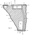
- Figure 1 shows the principle of the hearing aid according to the invention in a very schematic manner.
- the hearing aid is shown cut in its already individualized state and parallel to the axis of the auditory canal. It essentially has the shape of an irregular truncated cone with a lateral surface M, a larger end face AS facing in the auditory canal and a smaller end face IS facing inward in the auditory canal.
- the hearing aid essentially consists of a shaped body 1, the shape of which is adapted to the auditory canal and at least on the lateral surface M, that is, where it touches the auditory canal wall when the device is being worn, as already described, is covered with a membrane 2.
- the hearing aid also has a skeleton, which essentially consists of three parts: an outer support element 3, which essentially forms the outer end face AS of the device, an inner support element 4, which essentially forms the inner end face of the device, and a connecting element 5, that connects the two support elements 3 and 4 together.
- the connecting element 5 serves to hold the two support elements 3 and 4 in a mutual position before the casting of the molded body, which roughly corresponds to an auditory canal.
- the connecting element 5 is advantageously deformable to a limited extent, so that the mutual position of the support elements 3 and 4 can be adapted to the individual auditory canal as a first individualization step.
- the outer support element 3 carries a microphone 31, for which it is provided with sound passage openings 32 at the corresponding point. Furthermore, the outer support element 3 forms a closable battery compartment 33 and carries a pouring or injection opening 34.
- the inner support element 4 carries a loudspeaker 41 and is also provided with sound passage openings 42.
- the membrane 2 which surrounds the molded body at least on its lateral surface M, is attached to the two support elements around the two end faces AS and IS (positions X in the figure).
- the membrane 2 can also completely span the inner end face IS. It can also partially span the outer end face, but must leave the pouring or injection opening 34 and the battery compartment 33 freely accessible.
- the amplifier electronics can either be carried by one of the support elements or by the connecting element. It can also be cast into the molded body without special attachment to the skeleton.
- the skeleton is advantageously made of plastic.
- the membrane can be attached to the support elements, for example by welding, by gluing or by appropriate tensioning elements. Further fastening options are described in connection with FIGS. 2 to 4.
- the general hearing aid from which the individualized hearing aid shown schematically in FIG. 1 is produced differs from this in that the molded body 1 is only present as an undetermined casting cavity between the support elements and the membrane.
- the membrane 2 fastened to the support elements 3 and 4 thus loosely surrounds the skeleton and, together with the support elements, forms a casting space which surrounds the skeleton in a substantially tubular manner and which opens out to the outside through the pouring channel 34.
- the casting space between the membrane and the skeleton is poured out through the casting channel 34 with a suitable plastic, while the hearing aid is positioned in the auditory canal.
- the plastic hardens to an individualized molded body 1.
- the requirements for the plastic are that it can be easily poured in through the pouring channel and that it hardens quickly. Of course, it must be skin-friendly.
- the casting compound made by 3M under the name Imprint® and mainly used in dental technology based on vinyl polysiloxane is very suitable for the present application.
- This two-component casting compound is available in easy-to-use twin cartridges with mixing tips, which can be placed directly on the pouring channel 34.
- casting compounds can also be used. Such materials are advantageously used that do not split off any low molecular weight residues during the polymerization.
- Additives for example small foam bodies or hollow glass spheres, can be added to the casting composition to improve the properties of the molded body as a sound and vibration damper.
- the steps required to individualize the general hearing aid are deforming the skeleton and casting the molded body. Both steps can be carried out by the hearing aid consultant without any problems, such that the user can take the hearing aid with him after a session and that the manufacturer only has to process general hearing aids.
- FIGS. 2 to 4 differ from one another essentially in that the electronic components are accessible to different extents.
- the principle described in connection with FIG. 1 has been retained in all embodiments.
- FIG. 2 shows a first exemplary embodiment of the hearing aid according to the invention, again in section parallel to the auditory canal axis.
- the device is positioned in an auditory canal, the auditory canal walls being indicated by the lines G.
- the hearing aid shown is already individualized. It has a skeleton, which in turn consists of an outer support element 3, an inner support element 4 and a connecting element 5 and which carries the electronic components.
- This skeleton is arranged in a cast molded body 1, the surface of which facing the auditory canal is covered by a sack-shaped membrane 2.
- the two support elements 3 and 4 are designed as an inner capsule 4.1 with an inner closing element 4.2 and an outer capsule 3.1 with an outer closing element 3.2, through which an at least partial accessibility of the electronic components on the individualized hearing aid.
- the loudspeaker 41 is accommodated in the inner capsule 4.1 and is inserted through its opening before the closing element 4.2 is placed on it.
- the microphone 31 is advantageously accommodated in correspondingly arranged compartments in a microphone compartment 31.1 and a battery in a battery compartment 33.
- the amplifier electronics 6 can also be accommodated in the outer capsule 3.1.
- the electrical connections between the electronic components of the hearing aid run, for example, through the deformable connecting element 5.
- the pouring channel 34 is also arranged, for example molded onto the outer capsule 3.1.
- the openings of the individual compartments of the outer capsule 3.1 and the opening of the pouring channel 34 advantageously lie essentially in one plane, so that they can be closed together by the closing element 3.2.
- separate closing elements can also be provided for the different openings or partial areas of the common closing element 3.2 can be designed for individual of the openings in such a way that they can be opened and closed without the entire closing element 3.2 having to be opened.
- the battery compartment 33 is closed with such a partial closing element 33.1 and is therefore very easily accessible to the user.
- the sack-shaped membrane 2 has a main opening, the edge of which is fastened around the region in which the opening of the outer capsule 3.1 and the opening of the pouring channel 34 are arranged such that the entire skeleton essentially except for the opening of the pouring channel 34 and the opening of the outer capsule 3.1 is enclosed by the membrane 2.
- the membrane 2 is fastened around the outer capsule by an outer membrane fixing means, which for example consists of a fixing ring 10 (shown on the left side of the figure) arranged in a form-fitting manner around the outer capsule or by a correspondingly positive design of the edge areas of the closing element 3.2 (on shown on the right side of the figure). If the membrane 2 is fastened to the outer capsule 3.1 by the closing element 3.2, it is necessary that the closing element 3.2, as shown in the figure for the battery compartment 33, also have a removable partial area or at least one opening for the pouring channel 34.
- the membrane 2 is fastened with an inner membrane fixing means, wherein it spans the speaker opening (as shown) or can have a further opening in this area.
- the inner membrane fixation means is, for example, the perforated inner closing element 4.2 which fits the opening of the inner capsule 4.1 and which holds the membrane 2 around the opening of the capsule 4.1 in such a way that the casting compound cannot enter the opening which spans the capsule opening Part 21 of the membrane 2 protects mechanically in use and does not represent an obstacle to the sound of the loudspeaker (sound passage openings).
- That part of the opening of the outer capsule 3.1 which lies above the microphone compartment 31.1 can also be covered with a membrane. As shown in FIG. 1, this can be achieved with a separate piece 22 of the membrane clamped between the closing element 4.2 and the capsule wall, or in such a way that the membrane 2 also stretches in one piece over this opening, being held in the same way as at the Opening the inner capsule 3.1.
- the closing element 3.2 is advantageously perforated.
- the membrane 2 can also be welded or glued to the capsules or the corresponding closing elements, as already mentioned.
- FIGS. 1 and 2 show a further embodiment of the hearing aid according to the invention.
- the principle in turn corresponds to that described in connection with FIG. 1 and also the basic components of the hearing aid, so that both no longer need to be described.
- the difference from the hearing aids according to FIGS. 1 and 2 is that the connecting element 5 is hollow and serves as a pressure compensation channel, for which purpose corresponding mouth openings 45 and 35 are provided in the inner (4) and in the outer support element 3.
- the pouring opening 34 is arranged such that it opens into the battery compartment 33.
- the inner end face IS is covered with a separate membrane piece 46, the area of the microphone 31 and the outer mouth opening 45 of the pressure compensation channel with a separate membrane piece 36.
- Microphone 31 and loudspeaker 41 are cast directly by the casting compound or can be surrounded on the molded body side with a sound insulation material 37.
- FIG. 3 shows the hearing aid in the general state as it is delivered by the manufacturer.
- Figure 4 shows the hearing aid in the ear canal G, ready for pouring.
- the battery and the battery compartment cover are removed.
- the separate membrane pieces 36 and 46 (FIG. 3) are removed, and by means of the pressure equalization channel with a wire 7, a protective element 48 is attached to the inner end face IS of the hearing aid, by means of which not only the eardrum is to be protected when pouring, but also to help position the not yet individualized hearing aid in the ear canal.
- the protective element 48 consists for example of foam.
- the wire 7 carrying the protective element can additionally serve as an aid for inserting the hearing aid into the auditory canal and for removing it.
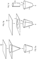
- the membrane Before pouring, that is to say in the general state of the hearing aid, the membrane must already have a shape corresponding to a certain extent to the auditory canal, so that in the individualized state of the hearing aid it spans the molded body without wrinkles. In particular, it should be possible to fasten it around its main opening (outer end face) and around the opening on the inner end face as wrinkle-free as possible. To do this, the membrane must be in the form of a sack that tapers away from the main opening. Such a membrane bag can, as shown in FIGS . 5a to 5c , be produced in different ways.
- a bag S can be drawn from a flat piece ME of a membrane.
- This method of production requires sufficient deformability of the membrane, but is particularly advantageous if the membrane is to span the inner end face of the hearing aid, that is, if the membrane bag is to have only one main opening but no further opening.
- FIG. 5b shows a method for producing a membrane bag S, likewise from a flat membrane piece ME, from which a piece K is cut in the form of a unwound truncated cone. This piece of K is welded to the membrane bag S with a main opening H and a further opening W.
- FIG. 5c shows the production of a membrane bag again with a main opening H and a further opening W from a piece of membrane hose MS by expanding its one end to a larger diameter.
- this can be applied to a second layer (intermediate layer) which is arranged on the finished hearing aid between the membrane and the molded body, that is to say not with the skin of the Ear canal comes into contact.
- this layer can be an open-cell foam or a mesh onto which the membrane is drawn. It turns out that such an intermediate layer can also facilitate the manufacture of the membrane bag.
Abstract
Description
Die Erfindung betrifft eine im Ohr zu tragende Hörhilfe und ein Verfahren zu deren Herstellung gemäss den Oberbegriffen der entsprechenden unabhängigen Patentansprüche.The invention relates to a hearing aid to be worn in the ear and a method for its production in accordance with the preambles of the corresponding independent claims.
Im Ohr zu tragende Hörhilfen weisen üblicherweise ein im Ohr gegen aussen angeordnetes Mikrophon, einen gegen das Ohrinnere weisenden Lautsprecher, eine verstärkende Elektronik und eine auswechselbare Batterie für den Betrieb auf, wobei alle diese elektronischen Bestandteile in einem Formkörper angeordnet sind, der in seiner Form mehr oder weniger der Form des Gehörganges angepasst ist und im Gehörgang getragen wird. Damit die Hörhilfe bequem getragen werden kann und damit sie ihre Funktion optimal ausüben kann, sind an den Formkörper verschiedene Anforderungen gestellt, die er je nach Ausführungsform mehr oder weniger gut erfüllt. Diese Anforderungen sind im wesentlichen die folgenden:
- Der Formkörper soll möglichst gut in den Gehörgang passen, damit er gut sitzt und trotzdem bequem ist.
- Der Formkörper soll leicht in den Gehörgang einführbar und aus dem Gehörgang entfernbar sein.
- Der Formkörper soll trotz guter Passform einen Druckausgleich im Gehörgang ermöglichen.
- Der Formkörper soll eine Rückkoppelung des durch den Lautsprecher erzeugten Schalls zum Mikrophon möglichst verhindern.
- Der Formkörper soll gut hautverträglich sein, er soll insbesondere eine Belüftung der Haut des Gehörganges ermöglichen und Schweiss- und Cerumenausscheidung nicht anregen.
- Der Formkörper soll unempfindlich sein gegen die Ausscheidungen des Gehörganges und einfach von diesen zu reinigen, insbesondere soll er auch die elektronischen Bestandteile der Hörhilfe vor diesen Ausscheidungen schützen.
- The molded body should fit into the ear canal as well as possible so that it sits well and is still comfortable.
- The molded body should be easy to insert into the auditory canal and removable from the auditory canal.
- The molded body should enable pressure equalization in the ear canal despite a good fit.
- The molded body is intended to prevent feedback of the sound generated by the loudspeaker to the microphone as far as possible.
- The molded body should be well tolerated by the skin, in particular it should allow ventilation of the skin of the ear canal and should not stimulate sweat and cerumen excretion.
- The molded body should be insensitive to the excretions of the auditory canal and easy to clean from them, in particular it should also protect the electronic components of the hearing aid from these excretions.
Zu diesen Anforderungen, die die Funktion der Hörhilfe und deren Tragkomfort betreffen, kommen ökonomische Anforderungen derart, dass der Formkörper einfach herstellbar sein soll. Es könnte ebenfalls aus ökonomischen Gründen zusätzlich wünschbar sein, dass die elektronischen Bestandteile zugänglich in der Hörhilfe integriert sind, damit sie ausgewechselt werden können.In addition to these requirements, which relate to the function of the hearing aid and its comfort, there are economic requirements such that the molded body should be easy to manufacture. It could also be desirable for economic reasons that the electronic components are integrated in the hearing aid so that they can be replaced.
Den genannten Anforderungen genügen die bekannten, im Ohr zu tragenden Hörhilfen in verschiedenem Masse. Im folgenden sollen einige davon kurz beschrieben und mit der obigen Anforderungsliste verglichen werden.The well-known hearing aids to be worn in the ear meet the requirements mentioned to a varying degree. Some of these are briefly described below and compared with the list of requirements above.
Die am häufigsten angewendete Methode zur Herstellung von im Ohr zu tragenden Hörhilfen besteht darin, dass durch einen Hörhilfenberater, der gleichzeitig die Hörschwächen des potentiellen Anwenders untersucht, ein Silikonabguss des Gehörganges hergestellt wird, dass nach diesem Silikonabguss ein transparentes, positives Modell des Gehörganges erstellt wird und dass in dieses Modell ein mit Hilfe von Licht polymerisierender Kunststoff gegossen wird, der von aussen nach innen bis zu einer bestimmten Schichtdicke härtet. Auf diese Art und Weise entsteht ein hohler Formkörper, in dem die elektronischen Bestandteile der Hörhilfe eingebaut werden, wobei gegen das Ohrinnere mindestens eine Öffnung für den Lautsprecher und für einen Druckausgleichskanal angeordnet werden. Gegen den Ausgang des Gehörganges wird der Formkörper mit einem Deckel abgeschlossen, der seinerseits eine Öffnung für den Druckausgleichskanal und ein separates Fach für eine auswechselbare Batterie enthält.The most frequently used method for the production of hearing aids to be worn in the ear is that a hearing aid consultant, who at the same time examines the hearing impairments of the potential user, produces a silicone cast of the ear canal, so that a transparent, positive model of the ear canal is created after this silicone cast and that in this model a plastic polymerizing with the help of light is poured, which hardens from the outside in to a certain layer thickness. In this way, a hollow molded body is formed in which the electronic components of the hearing aid are installed, with at least one opening for the loudspeaker and for a pressure equalization channel being arranged against the inside of the ear. Towards the exit of the auditory canal, the molded body is closed with a cover, which in turn contains an opening for the pressure compensation channel and a separate compartment for a replaceable battery.
Die derart hergestellte Hörhilfe weist einen Formkörper mit einer sehr guten Passform auf, wobei dieser aber die Haut des Gehörganges derart lückenlos abdeckt, dass von einer Belüftung nicht die Rede sein kann. Dies führt auch unweigerlich zu erhöhter Ausscheidung von Schweiss und Cerumen. Der zwischen Trommelfell und Hörhilfe frei bleibende Teil des Gehörganges ist durch den Druckausgleichskanal gegen aussen offen, sodass ein Druckausgleich stattfinden und auch Feuchtigkeit entweichen kann. Der Druckausgleichskanal kann aber seinerseits die Rückkoppelung zwischen Lautsprecher und Mikrophon zu erhöhen.The hearing aid produced in this way has a molded body with a very good fit, but this covers the skin of the auditory canal to such an extent that there can be no question of ventilation. This inevitably leads to increased excretion of sweat and cerumen. The part of the ear canal that remains free between the eardrum and the hearing aid is open to the outside through the pressure equalization channel, so that pressure equalization can take place and moisture can also escape. The pressure equalization channel can in turn increase the feedback between loudspeaker and microphone.
Ein weiterer Nachteil dieser Hörhilfe besteht darin, dass die Öffnungen zu Lautsprecher und Druckausgleichskanal leicht mit Cerumen verstopfen können, wobei diese aber mit einer flüssigkeitsundurchlässigen aber gasdurchlässigen Membran abgedeckt sein können, wie dies gemäss der europäischen Patentanmeldung Nr.0310866 (publiziert 12.4.89) vorgeschlagen wird.A further disadvantage of this hearing aid is that the openings to the loudspeaker and pressure equalization channel can easily become clogged with cerumen, although these can be covered with a liquid-impermeable but gas-permeable membrane, as proposed according to European patent application No. 0310866 (published April 12, 1989) becomes.
Das beschriebene Verfahren zur Herstellung des Hörgerätes ist aufwendig, weil der Formkörper in mehreren positiv-negativ-Schritten gegossen werden muss und weil diese Herstellungsschritte derart sind, dass sie nicht vom Hörhilfenberater selbst ausgeführt werden können. Das heisst mit anderen Worten, der Hersteller der Hörhilfen muss sich mit der individuellen Fertigstellung einzelner, anwenderspezifischer Geräte befassen.The described method for producing the hearing aid is complex because the molded body has to be cast in several positive-negative steps and because these production steps are such that they cannot be carried out by the hearing aid consultant himself. In other words, the manufacturer of the hearing aids must deal with the individual completion of individual, user-specific devices.
Zur Vereinfachung des Herstellungsverfahrens sind verschiedene Vorschläge gemacht worden. Nach US-Patentschrift Nr. 4962537 wird beispielsweise vorgeschlagen, den Formkörper in Form eines doppelwandigen Sacks aus einem flexiblen Material vorzusehen, wobei direkt im Ohr des Anwenders zwischen die beiden Wandungen eine erhärtende Kunststoffmasse gepresst wird. Mit dieser Methode können einige Verfahrensschritte bei der Herstellung eingespart werden, aber der gegossene Formkörper muss trotzdem noch nachbearbeitet werden, insbesondere müssen an ihm eine Öffnungen für einen Druckausgleichskanal und für den Lautsprecher nachträglich angebracht werden, und es ist zweifelhaft, ob dies vom Hörhilfenberater selbst durchgeführt werden kann.Various proposals have been made to simplify the manufacturing process. According to US Pat. No. 4962537, it is proposed, for example, to provide the shaped body in the form of a double-walled sack made of a flexible material, a hardening plastic compound being pressed directly in the user's ear between the two walls. This method can save some procedural steps in production, but the cast molding still has to be reworked, in particular an opening for a pressure equalization channel and for the loudspeaker must be retrofitted to it, and it is doubtful whether this was done by the hearing aid consultant himself can be.
Dasselbe gilt für die Hörhilfe gemäss der internationalen Patentanmeldung Nr. WO92/03894, deren Formkörper direkt in den Hörgang gegossen wird.The same applies to the hearing aid according to international patent application No. WO92 / 03894, the molded body of which is poured directly into the auditory canal.
Die beiden genannten Herstellungsverfahren sind zwar einfacher als das eingangs beschriebene Verfahren, verbessern aber die Nachteile bezüglich Hautkontakt und Rückkoppelung nicht. Dasselbe gilt für die Hörhilfe gemäss US Patent Nr. 4834211, bei der als Formkörper ein die elektronischen Bestandteile der Hörhilfe umgebender Ballon dient, der bei jedem Einführen ins Ohr mit einer entsprechenden Pumpe aufgeblasen wird. Bei einer solchen Hörhilfe sind wiederum Hautkontakt und Rückkoppelung nicht verbessert und es kann wohl nicht mehr von einfachem Einführen ins Ohr die Rede sein.Although the two production processes mentioned are simpler than the process described at the outset, they do not improve the disadvantages with regard to skin contact and feedback. The same applies to the hearing aid according to US Pat. No. 4,834,211, in which a balloon surrounding the electronic components of the hearing aid is used as the molded body and is inflated with a corresponding pump each time it is inserted into the ear. With such a hearing aid, skin contact and feedback are again not improved and it can no longer be said that they are simply inserted into the ear.
Es ist nun die Aufgabe der Erfindung, eine im Ohr zu tragende Hörhilfe mit einem an einen individuellen Gehörgang angepassten Formkörper zu schaffen, wobei die Hörhilfe einerseits in Bezug auf den Tragkomfort gegenüber bekannten derartigen Hörhilfen Verbesserungen aufweist und andererseits in einem einfacheren Verfahren hergestellt, insbesondere individualisiert werden kann. Ferner ist ein Verfahren anzugeben, nach dem die Hörhilfe hergestellt, insbesondere individualisiert wird.It is now the object of the invention to provide a hearing aid to be worn in the ear with a shaped body adapted to an individual ear canal, the hearing aid on the one hand having improvements in terms of wearing comfort compared to known hearing aids of this type and on the other hand being manufactured in a simpler process, in particular individualized can be. Furthermore, a method is to be specified according to which the hearing aid is manufactured, in particular individualized.
Das erfindungsgemässe Verfahren ist grob umrissen das folgende: Es wird serienmässig eine generelle (noch nicht an einen individuellen Gehörgang angepasste) Hörhilfe hergestellt. Diese weist ein vorteilhafterweise begrenzt plastisch verformbares Skelett auf, das die elektronischen Bestandteile der Hörhilfe trägt und an dem eine flexible Membran derart befestigt ist, dass durch Skelett und Membran ein Giessraum gebildet wird, der gegen aussen einen offenen Giesskanal aufweist. Die Hörhilfe wird nun individualisiert (an einen individuellen Gehörgang angepasste), indem das Skelett entsprechend der individuellen Gehörgangform verformt wird, indem die derart bereits teilweise individualisierte Hörhilfe im Ohr positioniert und dann der Giessraum mit einer erhärtenden Kunststoffmasse ausgegossen wird, wobei sich die Membran verformt und der entstehende Formkörper sich entsprechend dem Gehörgang formt. Dabei sind Skelett und Membran derart ausgebildet und aneinander befestigt, dass keine Nacharbeit der durch Skelettverformung und Giessen des Formkörpers individualisierten Hörhilfe notwendig ist.The method according to the invention is roughly outlined as follows: A general hearing aid (not yet adapted to an individual auditory canal) is produced as standard. This has an advantageously plastically deformable skeleton which carries the electronic components of the hearing aid and to which a flexible membrane is attached in such a way that a skeleton and membrane form a casting space which has an open casting channel towards the outside. The hearing aid is now individualized (adapted to an individual ear canal) by deforming the skeleton according to the individual shape of the ear canal, by positioning the hearing aid, which has already been partially customized in this way, in the ear and then pouring the casting space with a hardening plastic mass, the membrane deforming and the resulting molded body is shaped according to the ear canal. The skeleton and membrane are designed and attached to each other in such a way that no reworking of the hearing aid individualized by skeletal deformation and casting of the molded body is necessary.
Das Material und die Struktur der Membran sind derart, dass diese durch eine äusserst feine Porosität und entsprechende Oberflächenqualität für Gase durchlässig, für Flüssigkeiten aber undurchlässig ist und dass sie genügend elastisch ist, um sich beim Giessen des Formkörpers möglichst faltenfrei an die Gehörgangwand anlegen zu können. Die Membran ist dabei nicht nur senkrecht zu ihren Oberflächen gasdurchlässig sondern auch parallel dazu, derart, dass nicht nur durch diese Membran die beim Giessen verdrängte Luft entweichen kann, sondern dass sie auch als Druckausgleichsmittel und zur Belüftung der Gehörganghaut dienen kann. Diese Eigenschaft kann noch erhöht werden, indem die Membran an ihrer dem Skelett zugewandten Seite eine grober poröse Zwischenschicht trägt, die eine Schicht eines offenporigen Schaumstoffes oder ein Netz sein kann. Damit die Membran ihre Funktion auch langzeitig ausüben kann, ist sie zusätzlich wasser- und ölabstossend.The material and structure of the membrane are such that they are permeable to gases due to their extremely fine porosity and corresponding surface quality, but are impermeable to liquids and that they are sufficiently elastic to be able to fit the ear canal wall as wrinkle-free as possible . The membrane is not only gas-permeable perpendicular to its surfaces, but also parallel to it, such that not only can the air displaced during casting escape through this membrane, but that it can also serve as a pressure compensation means and for ventilation of the ear canal skin. This property can be further increased if the membrane has on its side facing the skeleton a coarse porous intermediate layer, which can be a layer of an open-cell foam or a mesh. So that the membrane can continue to function for a long time, it is also water and oil repellent.
Es zeigt sich, dass eine geschäumte und gereckte PTFE-Membran, die unter dem Namen GORE-TEX® von der Firma W.L. Gore & Co GmbH (D-88011 Putzbrunn bei München) hergestellt wird, die geforderten Eigenschaften aufweist und sich für die Anwendung eignet. Es handelt sich dabei um ein geschäumtes und gerecktes PTFE-Material (Polytetrafluoroethan), das eine feinst poröse Membran bildet. Diese Membran hat nicht nur die gefragten physikalischen Eigenschaften, sondern ist dazu sehr Haut- und Körper-freundlich (sie kann auch als provisorische Haut bei grossflächigen Wunden verwendet werden).It turns out that a foamed and stretched PTFE membrane, which is sold under the name GORE-TEX® by W.L. Gore & Co GmbH (D-88011 Putzbrunn near Munich) is manufactured, has the required properties and is suitable for the application. It is a foamed and stretched PTFE material (polytetrafluoroethane) that forms a very porous membrane. This membrane not only has the requested physical properties, but is also very kind to the skin and body (it can also be used as a provisional skin for large wounds).
Als weitere Membranmaterialien sind aus Kunststoffasern beispielsweise gewebte, gestrickte oder gewirkte Materialien denkbar, die mindestens auf der dem Gehörgang zugewandten Oberfläche beschichtet sind mit einer öl- und wasserabstossenden Schicht. Diese Schicht kann beispielsweise eine aufgedampfte Schicht von Parylen® (Union Carbide Corp., USA) oder Silan sein.Woven, knitted or knitted materials made of plastic fibers are conceivable as further membrane materials, which are coated with an oil and water-repellent layer at least on the surface facing the ear canal. This layer can be, for example, an evaporated layer of Parylen® (Union Carbide Corp., USA) or silane.
Anhand der folgenden Figuren sollen nun das erfindungsgemässe Herstellungsverfahren und die nach dem Verfahren hergestellte Hörhilfe anhand einiger beispielhafter Ausführungsformen detailliert beschrieben werden.Using the following figures, the manufacturing method according to the invention and the hearing aid manufactured according to the method will now be described in detail using some exemplary embodiments.
Dabei zeigen:
-
Figur 1 - ein Schema der wichtigsten Teile der erfindungsgemässen Hörhilfe zur Erklärung ihrer Funktionen (Schnitt parallel zur Gehörgangachse);
-
Figur 2 - eine beispielhafte Ausführungsform der erfindungsgemässen individualisierten Hörhilfe, parallel zur Gehörgangachse geschnitten;
-
Figuren 3 und 4 - eine weitere, beispielhafte Ausführungsformen der erfindungsgemässen Hörhilfe in generellem Zustand (
Figur 3 und unmittelbar vor dem Giessen des Formkörpers); - Figuren 5a bis 5c
- verschiedene Verfahren zur Herstellung eines Membransackes für die erfindungsgemässe Hörhilfe.
- Figure 1
- a diagram of the most important parts of the hearing aid according to the invention to explain their functions (section parallel to the auditory canal axis);
- Figure 2
- an exemplary embodiment of the individualized hearing aid according to the invention, cut parallel to the auditory canal axis;
- Figures 3 and 4
- a further, exemplary embodiments of the hearing aid according to the invention in a general state (FIG. 3 and immediately before the molding is cast);
- Figures 5a to 5c
- Various methods for producing a membrane bag for the hearing aid according to the invention.
Figur 1 zeigt das Prinzip der erfindungsgemässen Hörhilfe in einer sehr schematischen Art und Weise. Die Hörhilfe ist dabei in ihrem bereits individualisierten Zustand und parallel zur Achse des Gehörganges geschnitten dargestellt. Sie hat im wesentlichen die Form eines unregelmässigen Kegelstumpfes mit einer Mantelfläche M, einer im Gehörgang gegen aussen gerichteten, grösseren Stirnseite AS und einer im Gehörgang gegen innen gewandten, kleineren Stirnseite IS. Figure 1 shows the principle of the hearing aid according to the invention in a very schematic manner. The hearing aid is shown cut in its already individualized state and parallel to the axis of the auditory canal. It essentially has the shape of an irregular truncated cone with a lateral surface M, a larger end face AS facing in the auditory canal and a smaller end face IS facing inward in the auditory canal.
Die Hörhilfe besteht im wesentlichen aus einem Formkörper 1, der in seiner Form dem Gehörgang angepasst ist und mindestens auf der Mantelfläche M, das heisst da, wo er die Gehörgangwand beim Tragen des Gerätes berührt, wie bereits beschrieben mit einer Membran 2 überdeckt ist. Die Hörhilfe besitzt ferner ein Skelett, das im wesentlichen aus drei Teilen besteht: aus einem äusseren Tragelement 3, das im wesentlichen die äussere Stirnseite AS des Gerätes bildet, einem inneren Tragelement 4, das im wesentlichen die innere Stirnfläche des Gerätes bildet, und einem Verbindungselement 5, das die beiden Tragelemente 3 und 4 miteinander verbindet. Das Verbindungselement 5 dient dazu, die beiden Tragelemente 3 und 4 vor dem Giessen des Formkörpers in einer gegenseitigen Lage zu halten, die grob einem Gehörgang entspricht. Das Verbindungselement 5 ist dabei vorteilhafterweise beschränkt deformierbar, sodass als erster Individualisierungsschritt die gegenseitige Lage der Tragelemente 3 und 4 dem individuellen Gehörgang angepasst werden kann.The hearing aid essentially consists of a shaped
Das äussere Tragelement 3 trägt ein Mikrophon 31, für das es an der entsprechenden Stelle mit Schalldurchtrittsöffnungen 32 versehen ist. Ferner bildet das äussere Tragelement 3 ein verschliessbares Batteriefach 33 und trägt eine Eingiess- oder Einspritzöffnung 34.The
Das innere Tragelement 4 trägt einen Lautsprecher 41 und ist ebenfalls mit Schalldurchtrittsöffnungen 42 versehen.The inner support element 4 carries a
Die Membran 2, die den Formkörper mindestens auf seiner Mantelfläche M umgibt, ist rund um die beiden Stirnseiten AS und IS an den beiden Tragelementen befestigt (Stellen X in der Figur). Die Membran 2 kann zusätzlich die innere Stirnfläche IS ganz überspannen. Sie kann auch die äussere Stirnfläche teilweise überspannen, muss aber die Eingiess- oder Einspritzöffnung 34 und das Batteriefach 33 frei zugänglich lassen.The
Die Verstärkerelektronik (nicht dargestellt) kann entweder von einem der Tragelemente oder vom Verbindungselement getragen werden. Sie kann auch ohne spezielle Befestigung am Skelett in den Formkörper eingegossen sein.The amplifier electronics (not shown) can either be carried by one of the support elements or by the connecting element. It can also be cast into the molded body without special attachment to the skeleton.
Das Skelett besteht vorteilhafterweise aus Kunststoff. Die Membran kann an den Tragelementen beispielsweise durch Schweissung, durch Kleben oder durch entsprechende Spannelemente befestigt sein. Weitere Befestigungsmöglichkeiten werden im Zusammenhang mit den Figuren 2 bis 4 beschrieben.The skeleton is advantageously made of plastic. The membrane can be attached to the support elements, for example by welding, by gluing or by appropriate tensioning elements. Further fastening options are described in connection with FIGS. 2 to 4.
Die generelle Hörhilfe, aus der die in der Figur 1 schematisch dargestellte, individualisierte Hörhilfe hergestellt wird, unterscheidet sich von dieser dadurch, dass der Formkörper 1 nur als noch unbestimmter Giessholraum zwischen Tragelementen und Membran vorhanden ist. Die an den Tragelementen 3 und 4 befestigte Membran 2 umgibt also das Skelett locker und bildet mit den Tragelementen zusammen einen das Skelett im wesentlichen rohrförmig umgebenden Giessraum, der sich durch den Giesskanal 34 gegen aussen öffnet.The general hearing aid from which the individualized hearing aid shown schematically in FIG. 1 is produced differs from this in that the molded
Der Giessraum zwischen Membran und Skelett wird durch den Giesskanal 34 mit einem geeigneten Kunststoff ausgegossen, während die Hörhilfe im Gehörgang positioniert ist. Der Kunststoff erhärtet zum individualisierten Formkörper 1. Die Anforderungen an den Kunststoff sind, dass er einfach durch den Giesskanal eingegossen werden kann und dass er schnell aushärtet. Selbstverständlich muss er Haut-verträglich sein.The casting space between the membrane and the skeleton is poured out through the casting
Es zeigt sich, dass die von der Firma 3M unter dem Namen Imprint® hergestellte, vor allem in der Dentaltechnik angewendete Giessmasse auf der Basis von Vinylpolysiloxan für die vorliegende Anwendung sehr geeignet ist. Diese Zweikomponenten-Giessmasse ist in einfach handhabbaren Zwillingskartuschen mit Mischkanülen erhältlich, die direkt auf den Giesskanal 34 aufgesetzt werden können.It can be seen that the casting compound made by 3M under the name Imprint® and mainly used in dental technology based on vinyl polysiloxane is very suitable for the present application. This two-component casting compound is available in easy-to-use twin cartridges with mixing tips, which can be placed directly on the pouring
Selbstverständlich lassen sich auch andere Giessmassen verwenden. Vorteilhafterweise werden derartige Materialien angewendet, die bei der Polymerisation keine niedermolekularen Reste abspalten. Der Giessmasse können zur Verbesserung der Eigenschaften des Formkörpers als Schall- und Vibrationsdämpfer Zusätze, beispielsweise kleine Schaumstoffkörper oder hohle Glaskugeln, zugesetzt werden.Of course, other casting compounds can also be used. Such materials are advantageously used that do not split off any low molecular weight residues during the polymerization. Additives, for example small foam bodies or hollow glass spheres, can be added to the casting composition to improve the properties of the molded body as a sound and vibration damper.
Während dem Giessvorgang, insbesondere auch während der letzten Phasen dieses Giessvorganges, wenn der Formkörper bereits stark an der Gehörgangwand anliegt, findet durch die Membran und die Zwischenschicht, wenn eine solche vorgesehen ist, parallel zu deren Hauptflächen ein Druckausgleich statt, sodass sich durch das Giessen im durch den Formkörper abgeschlossenen Gehörgang kein Druck aufbauen kann.During the casting process, in particular also during the last phases of this casting process, when the molded body is already strongly against the auditory canal wall, pressure is equalized through the membrane and the intermediate layer, if one is provided, parallel to their main surfaces, so that the casting takes place no pressure can build up in the ear canal closed by the molded body.
Die Herstellung der in der Figur 1 schematisch dargestellten Hörhilfe geht nun beispielsweise in den folgenden Schritten vor:
- Skelett herstellen, beispielsweise durch Spritzgiessen eines geeigneten Kunststoffes.
Lautsprecher 41,Mikrophon 31 und Verstärkerelektronik am Skelett installieren und elektrisch miteinander undmit dem Batteriefach 33 verbinden.- Skelett
mit der Membran 2 umgeben und diese anden Tragelementen 3 und 4 befestigen (Stellen X). - Die in den ersten drei Schritten hergestellte generelle Hörhilfe durch entsprechende Deformation des Skeletts bzw. des
Verbindungselementes 5 grob an einen individuellen Gehörgang anpassen. - Grob angepasste Hörhilfe im Gehörgang positionieren und Formkörper durch Ausgiessen des Giessraums zwischen Membran und Skelett herstellen.
- Batterie einsetzen.
- Create a skeleton, for example by injection molding a suitable plastic.
- Install
loudspeaker 41,microphone 31 and amplifier electronics on the skeleton and connect them electrically to one another and to thebattery compartment 33. - Surround the skeleton with the
membrane 2 and attach it to thesupport elements 3 and 4 (positions X). - Roughly adapt the general hearing aid produced in the first three steps to an individual auditory canal by appropriately deforming the skeleton or the connecting
element 5. - Position the roughly adapted hearing aid in the ear canal and produce the molded body by pouring the casting space between the membrane and the skeleton.
- Insert the battery.
Die zur Individualisierung der generellen Hörhilfe notwendigen Schritte sind das Verformen des Skeletts und das Giessen des Formkörpers. Beide Schritte können ohne Probleme vom Hörhilfenberater durchgeführt werden, derart, dass der Anwender die Hörhilfe nach einer Session mitnehmen kann und dass der Fabrikant lediglich generelle Hörhilfen bearbeiten muss.The steps required to individualize the general hearing aid are deforming the skeleton and casting the molded body. Both steps can be carried out by the hearing aid consultant without any problems, such that the user can take the hearing aid with him after a session and that the manufacturer only has to process general hearing aids.
Die in den Figuren 2 bis 4 dargestellten, beispielhaften Ausführungsformen der erfindungsgemässen Hörhilfe unterscheiden sich voneinander im wesentlichen dadurch dass die elektronischen Bestandteile in verschiedenem Masse zugänglich sind. Das im Zusammenhang mit der Figur 1 beschriebene Prinzip ist in allen Ausführungsformen erhalten.The exemplary embodiments of the hearing aid according to the invention shown in FIGS. 2 to 4 differ from one another essentially in that the electronic components are accessible to different extents. The principle described in connection with FIG. 1 has been retained in all embodiments.
Figur 2 zeigt eine erste beispielhafte Ausführungsform der erfindungsgemässen Hörhilfe wiederum im Schnitt parallel zur Gehörgangachse. Das Gerät ist in einem Gehörgang positioniert, wobei die Gehörgangwände mit den Linien G angedeutet sind. Die dargestellte Hörhilfe ist bereits individualisiert. Sie besitzt ein Skelett, das wiederum aus einem äusseren Tragelement 3, einem inneren Tragelement 4 und einem Verbindungselement 5 besteht und das die elektronischen Bestandteile trägt. Dieses Skelett ist in einem gegossenen Formkörper 1 angeordnet, dessen gegen den Gehörgang gerichtete Oberfläche von einer sackförmigen Membran 2 bedeckt ist. FIG. 2 shows a first exemplary embodiment of the hearing aid according to the invention, again in section parallel to the auditory canal axis. The device is positioned in an auditory canal, the auditory canal walls being indicated by the lines G. The hearing aid shown is already individualized. It has a skeleton, which in turn consists of an
Die beiden Tragelemente 3 und 4 sind als eine innere Kapsel 4.1 mit einem inneren Schliesselement 4.2 und eine äussere Kapsel 3.1 mit einem äusseren Schliesselement 3.2 ausgebildet, durch die eine wenigstens teilweise Zugänglichkeit der elektronischen Bestandteile an der individualisierten Hörhilfe möglich wird.The two
In der inneren Kapsel 4.1 ist der Lautsprecher 41 untergebracht, der durch deren Öffnung eingeführt wird, bevor das Schliesselement 4.2 darauf gesetzt wird. In der äusseren Kapsel 3.1 sind vorteilhafterweise in entsprechend angeordneten Fächern das Mikrophon 31 in einem Mikrophonfach 31.1 und in einem Batteriefach 33 eine Batterie untergebracht. Auch die Verstärkerelektronik 6 kann in der äusseren Kapsel 3.1 untergebracht sein. Die elektrischen Verbindungen zwischen den elektronischen Bestandteilen der Hörhilfe verlaufen beispielsweise durch das deformierbare Verbindungselement 5.The
Im Bereiche der äusseren Kapsel 3.1 und ebenfalls gegen aussen offen ist auch der Giesskanal 34 angeordnet, beispielsweise an der äusseren Kapsel 3.1 angeformt. Die Öffnungen der einzelnen Fächer der äusseren Kapsel 3.1 und die Öffnung des Giesskanales 34 liegen vorteilhafterweise im wesentlichen in einer Ebene, sodass sie gemeinsam vom Schliesselement 3.2 geschlossen werden können. Es können für die verschiedenen Öffnungen aber auch separate Schliesselemente vorgesehen sein oder für einzelne der Öffnungen Teilbereiche des gemeinsamen Schliesselementes 3.2 derart ausgestaltet sein, dass sie geöffnet und geschlossen werden können, ohne dass das ganze Schliesselement 3.2 geöffnet werden muss. In der Figur 2 ist das Batteriefach 33 mit einem derartigen Teilschliesselement 33.1 abgeschlossen und dadurch für den Anwender sehr einfach zugänglich.In the area of the outer capsule 3.1 and also open to the outside, the pouring
Die sackförmige Membran 2 besitzt eine Hauptöffnung, deren Kante rund um den Bereich, in dem die Öffnung der äusseren Kapsel 3.1 und die Öffnung des Giesskanals 34 angeordnet sind, derart befestigt ist, dass das ganze Skelett im wesentlichen bis auf die Öffnung des Giesskanales 34 und die Öffnung der äusseren Kapsel 3.1 durch die Membran 2 umschlossen ist. Die Befestigung der Membran 2 rund um die äussere Kapsel wird übernommen durch ein äusseres Membranfixiermittel, das beispielsweise aus einem formschlüssig um die äussere Kapsel angeordneten Fixierring 10 (auf der linken Seite der Figur dargestellt) oder durch entsprechend formschlüssige Ausgestaltung der Randbereiche des Schliesselementes 3.2 (auf der rechten Seite der Figur dargestellt) bestehen kann. Wird die Membran 2 durch das Schliesselement 3.2 an der äusseren Kapsel 3.1 befestigt, ist es notwendig, dass das Schliesselement 3.2, wie dies in der Figur für das Batteriefach 33 dargestellt ist, auch für den Giesskanal 34 einen entfernbaren Teilbereich oder mindestens eine Öffnung aufweist.The sack-shaped
Rund um die Öffnung der inneren Kapsel 4.1 ist die Membran 2 mit einem inneren Membranfixiermittel befestigt, wobei sie die Lautsprecheröffnung überspannen (wie dargestellt) oder in diesem Bereiche eine weitere Öffnung aufweisen kann. Das innere Membranfixiermittel ist beispielsweise das formschlüssig auf die Öffnung der inneren Kapsel 4.1 passende, perforierte innere Schliesselement 4.2, das die Membran 2 rund um die Öffnung der Kapsel 4.1 derart festhält, dass die Giessmasse nicht in die Öffnung treten kann, das den die Kapselöffnung überspannenden Teil 21 der Membran 2 im Gebrauch mechanisch schützt und das für den Schall des Lautsprechers aber kein Hindernis darstellt (Schalldurchtrittsöffnungen).Around the opening of the inner capsule 4.1, the
Auch derjenige Teil der Öffnung der äusseren Kapsel 3.1, der über dem Mikrophonfach 31.1 liegt, kann mit einer Membran abgedeckt sein. Dies kann, wie in der Figur 1 dargestellt, mit einem zwischen Schliesselement 4.2 und Kapselwand eingeklemmten, separaten Stück 22 der Membran realisiert werden oder aber derart, dass die Membran 2 sich einstückig auch über diese Öffnung spannt, wobei sie in gleicher Weise festgehalten wird wie an der Öffnung der inneren Kapsel 3.1. Im das Mikrophonfach 31.1 überdeckenden Bereich ist das Schliesselement 3.2 vorteilhafterweise perforiert.That part of the opening of the outer capsule 3.1 which lies above the microphone compartment 31.1 can also be covered with a membrane. As shown in FIG. 1, this can be achieved with a
Die Membran 2 kann an den Kapseln oder den entsprechenden Schliesselementen wie bereits erwähnt auch angeschweisst oder angeklebt sein.The
Figuren 3 und 4 zeigen eine weitere Ausführungsform der erfindungsgemässen Hörhilfe. Das Prinzip entspricht wiederum dem im Zusammenhang mit der Figur 1 beschriebenen und auch die prinzipiellen Bestandteile der Hörhilfe, sodass beides nicht mehr beschrieben werden muss. Der Unterschied zu den Hörhilfen gemäss Figuren 1 und 2 besteht darin, dass das Verbindungselement 5 hohl ist und als Druckausgleichskanal dient, wozu im inneren (4) und im äusseren Tragelement 3 korrespondierende Mündungsöffnungen 45 und 35 vorgesehen sind. Ferner ist die Eingiessöffnung 34 derart angeordnet, dass sie ins Batteriefach 33 mündet. Die innere Stirnseite IS ist mit einem separaten Membranstück 46, der Bereich des Mikrophons 31 und der äusseren Mündungsöffnung 45 des Druckausgleichskanals mit einem separaten Membranstück 36 bedeckt. Mikrophon 31 und Lautsprecher 41 werden direkt von der Giessmasse umgossen oder können formkörperseitig mit einem Schallisolationsmaterial 37 umgeben sein. Figures 3 and 4 show a further embodiment of the hearing aid according to the invention. The principle in turn corresponds to that described in connection with FIG. 1 and also the basic components of the hearing aid, so that both no longer need to be described. The difference from the hearing aids according to FIGS. 1 and 2 is that the connecting
Figur 3 zeigt die Hörhilfe in generellem Zustand, wie sie vom Hersteller abgeliefert wird. FIG. 3 shows the hearing aid in the general state as it is delivered by the manufacturer.
Figur 4 zeigt die Hörhilfe im Gehörgang G, bereit zum Ausgiessen. Um die Eingiessöffnung 34 frei zu geben, sind Batterie und Batteriefachdeckel entfernt. Um die Mündungsöffnungen 35 und 45 des Druckausgleichskanals freizugeben, sind die separaten Membranstücke 36 und 46 (Fig. 3) entfernt, und durch den Druckausgleichskanal mit einem Draht 7 befestigt ist auf der inneren Stirnseite IS der Hörhilfe ein Schutzelement 48 angebracht, durch das nicht nur das Trommelfell beim Giessen geschützt werden soll, sondern das auch helfen soll, die noch nicht individualisierte Hörhilfe im Gehörgang zu positionieren. Das Schutzelement 48 besteht beispielsweise aus Schaumstoff. Der das Schutzelement tragende Draht 7 kann zusätzlich als Hilfe zum Einführen der Hörhilfe in den Gehörkanal und zu dessen Entfernung dienen. Figure 4 shows the hearing aid in the ear canal G, ready for pouring. In order to open the pouring
Die Membran muss vor dem Ausgiessen, also im generellen Zustande der Hörhilfe bereits eine einigermassen dem Gehörgang entsprechende Form aufweisen, damit sie den Formkörper im individualisierten Zustand der Hörhilfe faltenfrei umspannt. Insbesondere sollte sie rund um ihre Hauptöffnung (äussere Stirnseite) und rund um die Öffnung an der inneren Stirnseite möglichst faltenfrei befestigt werden können. Dazu muss die Membran in Form eines sich von der Hauptöffnung weg verjüngenden Sacks vorliegen. Ein derartiger Membransack kann, wie in den Figuren 5a bis 5c dargestellt, auf verschiedene Arten hergestellt werden.Before pouring, that is to say in the general state of the hearing aid, the membrane must already have a shape corresponding to a certain extent to the auditory canal, so that in the individualized state of the hearing aid it spans the molded body without wrinkles. In particular, it should be possible to fasten it around its main opening (outer end face) and around the opening on the inner end face as wrinkle-free as possible. To do this, the membrane must be in the form of a sack that tapers away from the main opening. Such a membrane bag can, as shown in FIGS . 5a to 5c , be produced in different ways.
Bei genügender Verformbarkeit der Membran kann ein derartiger Sack S, wie dies in der Figur 5a dargestellt ist, aus einem flachen Stück ME einer Membran gezogen werden. Diese Herstellungsweise bedingt eine genügende Verformbarkeit der Membran, ist aber insbesondere vorteilhaft, wenn die innere stirnseite der Hörhilfe von der Membran überspannt werden soll, das heisst, wenn der Membransack nur eine Hauptöffnung aber keine weitere Öffnung aufweisen soll.If the membrane is sufficiently deformable, such a bag S, as shown in FIG. 5a , can be drawn from a flat piece ME of a membrane. This method of production requires sufficient deformability of the membrane, but is particularly advantageous if the membrane is to span the inner end face of the hearing aid, that is, if the membrane bag is to have only one main opening but no further opening.
Figur 5b zeigt ein Verfahren zur Herstellung eines Membransackes S ebenfalls aus einem ebenen Membranstück ME, aus dem ein Stück K in der Form eines abgewickelten Kegelstumpfmantels geschnitten wird. Dieses Stück K wird zum Membransack S mit einer Hauptöffnung H und einer weiteren Öffnung W geschweisst. FIG. 5b shows a method for producing a membrane bag S, likewise from a flat membrane piece ME, from which a piece K is cut in the form of a unwound truncated cone. This piece of K is welded to the membrane bag S with a main opening H and a further opening W.
Figur 5c zeigt die Herstellung eines Membransackes wiederum mit Hauptöffnung H und weiterer Öffnung W aus einem Stück Membranschlauch MS durch Ausweitung seines einen Endes auf einen grösseren Durchmesser. FIG. 5c shows the production of a membrane bag again with a main opening H and a further opening W from a piece of membrane hose MS by expanding its one end to a larger diameter.
Um den Gasaustausch in der Richtung der Hauptflächen der Membran zu unterstützen, kann, wie bereits erwähnt, diese auf eine zweite Schicht (Zwischenschicht) aufgezogen sein, die an der fertigen Hörhilfe zwischen der Membran und dem Formkörper angeordnet ist, also nicht mit der Haut des Gehörganges in Berührung kommt. Diese Schicht kann, wie bereits erwähnt ein offenporiger Schaumstoff oder ein Netz sein, auf die die Membran aufgezogen ist. Es zeigt sich, dass eine derartige Zwischenschicht auch die Herstellung des Membransackes erleichtern kann.In order to support the gas exchange in the direction of the main surfaces of the membrane, as already mentioned, this can be applied to a second layer (intermediate layer) which is arranged on the finished hearing aid between the membrane and the molded body, that is to say not with the skin of the Ear canal comes into contact. As already mentioned, this layer can be an open-cell foam or a mesh onto which the membrane is drawn. It turns out that such an intermediate layer can also facilitate the manufacture of the membrane bag.
Claims (16)
Applications Claiming Priority (3)
| Application Number | Priority Date | Filing Date | Title |
|---|---|---|---|
| CH175793 | 1993-06-11 | ||
| CH1757/93 | 1993-06-11 | ||
| CH175793 | 1993-06-11 |
Publications (2)
| Publication Number | Publication Date |
|---|---|
| EP0629101A1 true EP0629101A1 (en) | 1994-12-14 |
| EP0629101B1 EP0629101B1 (en) | 2001-09-05 |
Family
ID=4217863
Family Applications (1)
| Application Number | Title | Priority Date | Filing Date |
|---|---|---|---|
| EP94810287A Expired - Lifetime EP0629101B1 (en) | 1993-06-11 | 1994-05-17 | Hearing aid to be worn in the ear and method for manufacturing the same |
Country Status (6)
| Country | Link |
|---|---|
| US (1) | US5530763A (en) |
| EP (1) | EP0629101B1 (en) |
| AT (1) | ATE205357T1 (en) |
| AU (1) | AU677647B2 (en) |
| DE (1) | DE59409849D1 (en) |
| DK (1) | DK0629101T3 (en) |
Cited By (10)
| Publication number | Priority date | Publication date | Assignee | Title |
|---|---|---|---|---|
| WO2000074915A2 (en) * | 2000-09-07 | 2000-12-14 | Phonak Ag | Method of producing hearing aids and a hearing aid |
| DE19843389C2 (en) * | 1998-09-22 | 2002-07-11 | Fariborz-Hassan Dirinpur | Perforated earmold for hearing aids |
| EP1432285A2 (en) * | 2003-12-30 | 2004-06-23 | Phonak Ag | Hydrophobic coating of individual hearing aid components |
| US7174028B1 (en) | 2000-09-07 | 2007-02-06 | Phonak Ag | Method for manufacturing hearing aids, and a hearing aid |
| EP1060640B2 (en) † | 1998-03-02 | 2007-03-14 | Phonak Ag | Hearing aid |
| DE102006014884B3 (en) * | 2006-03-30 | 2007-08-23 | Siemens Audiologische Technik Gmbh | In-the-ear hearing device e.g. headset, has elastic tape fixed within housing, where tape pulls face plate and/or module vertically to corresponding opening in housing under preloading |
| EP1758427A3 (en) * | 2005-08-26 | 2008-10-08 | Siemens Audiologische Technik GmbH | In-the-ear hearing aid with electronic module |
| EP2007171A3 (en) * | 2007-06-20 | 2009-11-11 | Siemens Medical Instruments Pte. Ltd. | Closing unit with component support for a hearing device |
| US8416975B2 (en) | 2008-04-02 | 2013-04-09 | Siemens Medical Instruments Pte. Ltd. | Hearing aid housing |
| WO2020225365A1 (en) * | 2019-05-09 | 2020-11-12 | Sivantos Pte. Ltd. | Method for adapting an otoplastic of a hearing aid, hearing aid, and hearing aid system |
Families Citing this family (72)
| Publication number | Priority date | Publication date | Assignee | Title |
|---|---|---|---|---|
| SE9402631L (en) * | 1994-08-04 | 1995-07-24 | Peter Joakim Lenz | Hearing aid device |
| US5818946A (en) * | 1996-03-22 | 1998-10-06 | Walter; Dieter Waldemar | Ruggedized solar charged hearing aid |
| EP0821541A3 (en) * | 1996-07-24 | 2004-06-02 | Bernafon AG | Hearing aid which is to be worn completely in the ear canal and which is individualised by moulding a body |
| EP0821542A3 (en) * | 1996-07-24 | 2004-06-02 | Bernafon AG | Hearing aid which is to be worn completely in the ear canal and which is individualised by moulding a body |
| EP0821543A3 (en) * | 1996-07-24 | 2004-06-02 | Bernafon AG | Membrane as outer surface of a hearing aid which is individualised by moulding a body |
| US7787647B2 (en) | 1997-01-13 | 2010-08-31 | Micro Ear Technology, Inc. | Portable system for programming hearing aids |
| US6754361B1 (en) * | 1997-04-17 | 2004-06-22 | 3M Innovative Properties Company | Ergonomic headset assembly |
| ITFO970022A1 (en) * | 1997-09-16 | 1999-03-16 | Otosan Di Gianardi Massimiliano | SAFETY ACCESSORY FOR FABRIC AND WAX CONES USED IN CLEANING THE EARPHONE CABLE |
| US6432247B1 (en) | 1997-12-18 | 2002-08-13 | Softear Technologies, L.L.C. | Method of manufacturing a soft hearing aid |
| US6254526B1 (en) | 1997-12-18 | 2001-07-03 | Softear Technologies, L.L.C. | Hearing aid having hard mounting plate and soft body bonded thereto |
| US6022311A (en) * | 1997-12-18 | 2000-02-08 | General Hearing Instrument, Inc. | Apparatus and method for a custom soft-solid hearing aid |
| US6728383B1 (en) | 1997-12-18 | 2004-04-27 | Softear Technologies, L.L.C. | Method of compensating for hearing loss |
| US6438244B1 (en) * | 1997-12-18 | 2002-08-20 | Softear Technologies | Hearing aid construction with electronic components encapsulated in soft polymeric body |
| US6695943B2 (en) | 1997-12-18 | 2004-02-24 | Softear Technologies, L.L.C. | Method of manufacturing a soft hearing aid |
| DE69833801T2 (en) | 1997-12-18 | 2006-11-16 | Softear Technologies, L.L.C. | BENDING HORIZONTAL DEVICE AND METHOD OF MANUFACTURING |
| US6473512B1 (en) | 1997-12-18 | 2002-10-29 | Softear Technologies, L.L.C. | Apparatus and method for a custom soft-solid hearing aid |
| US6434248B1 (en) * | 1997-12-18 | 2002-08-13 | Softear Technologies, L.L.C. | Soft hearing aid moulding apparatus |
| US6228020B1 (en) | 1997-12-18 | 2001-05-08 | Softear Technologies, L.L.C. | Compliant hearing aid |
| US6366863B1 (en) | 1998-01-09 | 2002-04-02 | Micro Ear Technology Inc. | Portable hearing-related analysis system |
| US6134333A (en) * | 1998-03-17 | 2000-10-17 | Sonic Innovations, Inc. | Disposable oleophobic and hydrophobic barrier for a hearing aid |
| US6167141A (en) * | 1998-04-30 | 2000-12-26 | Beltone Electronics Corporation | Multimaterial hearing aid housing |
| US20050141739A1 (en) * | 2003-02-28 | 2005-06-30 | Softear Technologies, L.L.C. (A Louisiana Limited Liability Company) | Soft hearing aid with stainless steel wire |
| US7217335B2 (en) * | 1998-05-26 | 2007-05-15 | Softear Technologies, L.L.C. | Method of manufacturing a soft hearing aid |
| US20080063231A1 (en) * | 1998-05-26 | 2008-03-13 | Softear Technologies, L.L.C. | Method of manufacturing a soft hearing aid |
| US6105713A (en) * | 1998-09-17 | 2000-08-22 | Sonic Innovations, Inc. | Cover movable by rotation forming a cerumen barrier in a hearing aid |
| US6393130B1 (en) | 1998-10-26 | 2002-05-21 | Beltone Electronics Corporation | Deformable, multi-material hearing aid housing |
| US6584207B1 (en) * | 1999-02-02 | 2003-06-24 | Beltone Electronics Corporation | Molded hearing aid housing |
| WO2001043489A2 (en) * | 1999-12-09 | 2001-06-14 | Sonionmicrotronic Nederland B.V. | Miniature microphone |
| US6532295B1 (en) * | 1999-12-10 | 2003-03-11 | Sonic Innovations, Inc. | Method for fitting a universal hearing device shell and conformal tip in an ear canal |
| ATE527827T1 (en) | 2000-01-20 | 2011-10-15 | Starkey Lab Inc | METHOD AND DEVICE FOR HEARING AID ADJUSTMENT |
| US7130437B2 (en) * | 2000-06-29 | 2006-10-31 | Beltone Electronics Corporation | Compressible hearing aid |
| US20020076060A1 (en) * | 2000-12-19 | 2002-06-20 | Hall Ronald W. | Programmable headset and programming apparatus and method |
| US7062058B2 (en) * | 2001-04-18 | 2006-06-13 | Sonion Nederland B.V. | Cylindrical microphone having an electret assembly in the end cover |
| US6937735B2 (en) * | 2001-04-18 | 2005-08-30 | SonionMicrotronic Néderland B.V. | Microphone for a listening device having a reduced humidity coefficient |
| US7136496B2 (en) * | 2001-04-18 | 2006-11-14 | Sonion Nederland B.V. | Electret assembly for a microphone having a backplate with improved charge stability |
| WO2003027231A2 (en) * | 2001-09-04 | 2003-04-03 | Bristol-Myers Squibb Company | Polynucleotide encoding adapter protein, pmn29 |
| US7239714B2 (en) | 2001-10-09 | 2007-07-03 | Sonion Nederland B.V. | Microphone having a flexible printed circuit board for mounting components |
| US20030123687A1 (en) * | 2001-11-27 | 2003-07-03 | Gn Resound A/S | Modular hearing aid assembly |
| US7103392B2 (en) * | 2002-01-15 | 2006-09-05 | 3M Innovative Properties Company | Wireless intercom system |
| US6993292B2 (en) * | 2002-02-26 | 2006-01-31 | 3M Innovative Properties Company | Self-monitoring radio network |
| DE10213844C1 (en) * | 2002-03-27 | 2003-10-02 | Siemens Audiologische Technik | Cerumen protection system for hearing aids |
| DE10219679A1 (en) * | 2002-05-02 | 2003-11-20 | Audio Service Gmbh As | Hearing aid or hearing aid parts for use in the ear canal and / or auricle of a wearer |
| US7043038B2 (en) * | 2002-07-24 | 2006-05-09 | Phonak Ag | In-the-ear hearing device |
| US8280082B2 (en) * | 2002-10-08 | 2012-10-02 | Sonion Nederland B.V. | Electret assembly for a microphone having a backplate with improved charge stability |
| JP4190499B2 (en) * | 2002-11-13 | 2008-12-03 | ベルナフォーン・アクチェンゲゼルシャフト | Set and method for manufacturing a hearing aid and hearing aid manufactured according to the method |
| US7120388B2 (en) * | 2002-12-16 | 2006-10-10 | 3M Innovative Properties Company | Wireless intercom system and method of communicating using wireless intercom system |
| WO2005051040A1 (en) * | 2003-11-13 | 2005-06-02 | Rafferty Richard A | Hearing aid that facilitates removel of earwax and trapping of moisture |
| DK1432285T3 (en) * | 2003-12-30 | 2016-08-01 | Sonova Ag | Hydrophobic coating of the individual components of the hearing instrument |
| US8150082B2 (en) * | 2005-02-22 | 2012-04-03 | Rion Co., Ltd. | Waterproof hearing aid |
| US20070003081A1 (en) * | 2005-06-30 | 2007-01-04 | Insound Medical, Inc. | Moisture resistant microphone |
| WO2007109517A1 (en) * | 2006-03-17 | 2007-09-27 | Donaldson Company, Inc | Hearing aid microphone cover |
| CN101507292A (en) * | 2006-08-31 | 2009-08-12 | 唯听助听器公司 | Filter for a hearing aid and a hearing aid |
| CA2601662A1 (en) | 2006-09-18 | 2008-03-18 | Matthias Mullenborn | Wireless interface for programming hearing assistance devices |
| US8846161B2 (en) * | 2006-10-03 | 2014-09-30 | Brigham Young University | Hydrophobic coating and method |
| AU2007303131A1 (en) * | 2006-10-03 | 2008-04-10 | Sonic Innovations, Inc. | Hydrophobic and oleophobic coating and method for preparing the same |
| JP5070296B2 (en) * | 2007-01-03 | 2012-11-07 | ヴェーデクス・アクティーセルスカプ | Hearing aid component and method of making a hearing aid component |
| DE102007014365A1 (en) * | 2007-03-26 | 2008-10-02 | Siemens Audiologische Technik Gmbh | Receiver housing for hearing aid i.e. in-the-ear hearing aid, has opening for barometric pressure balance of sound channel and covered by air permeable material such as air permeable membrane or tiling or porous material |
| WO2008154954A1 (en) * | 2007-06-18 | 2008-12-24 | Phonak Ag | Cover for apertures of an electric micro-device housing |
| US9071914B2 (en) * | 2007-08-14 | 2015-06-30 | Insound Medical, Inc. | Combined microphone and receiver assembly for extended wear canal hearing devices |
| US20090052709A1 (en) * | 2007-08-24 | 2009-02-26 | Smith Richard C | Hearing aid sleeve |
| EP2548383B1 (en) | 2010-03-19 | 2014-04-16 | Advanced Bionics AG | Waterproof acoustic element enclosure and apparatus including the same. |
| CN103404167B (en) | 2011-01-18 | 2017-03-01 | 领先仿生公司 | Moistureproof earphone and the implantable cochlear stimulation system including moistureproof earphone |
| US8761423B2 (en) | 2011-11-23 | 2014-06-24 | Insound Medical, Inc. | Canal hearing devices and batteries for use with same |
| US8682016B2 (en) | 2011-11-23 | 2014-03-25 | Insound Medical, Inc. | Canal hearing devices and batteries for use with same |
| DK2898704T3 (en) | 2012-09-18 | 2018-01-02 | Sonova Ag | ENCAPSULATED HEARING DEVICE |
| RU2016150946A (en) | 2014-05-30 | 2018-07-02 | Револ Текнолоджиз Инк. | ADJUSTABLE HEARING EAR INPUT |
| US10250964B2 (en) * | 2017-05-10 | 2019-04-02 | Logitech Europe S.A. | Apparatus and method of forming a custom earpiece |
| US10957445B2 (en) | 2017-10-05 | 2021-03-23 | Hill-Rom Services, Inc. | Caregiver and staff information system |
| DE102017219470A1 (en) * | 2017-11-02 | 2019-05-02 | Sivantos Pte. Ltd. | hearing Aid |
| US10869115B2 (en) | 2018-01-03 | 2020-12-15 | Logitech Europe S.A. | Apparatus and method of forming a custom earpiece |
| USD871130S1 (en) * | 2018-03-02 | 2019-12-31 | Gowanus Kitchen Lab, Llc | Frywall structure |
| US11554908B2 (en) | 2021-03-10 | 2023-01-17 | Susan C. Maccario | Combination dispensing and side disposal container and method |
Citations (7)
| Publication number | Priority date | Publication date | Assignee | Title |
|---|---|---|---|---|
| WO1988003740A1 (en) * | 1986-11-13 | 1988-05-19 | Epic Corporation | Method and apparatus for reducing acoustical distortion |
| GB2203379A (en) * | 1987-04-10 | 1988-10-19 | Oticon As | Making hearing aids |
| EP0289750A1 (en) * | 1987-05-06 | 1988-11-09 | Siemens Aktiengesellschaft | Method and device for making and ear tip |
| EP0310866A1 (en) * | 1987-10-05 | 1989-04-12 | Siemens Audiologische Technik GmbH | Device for closing the apertures of hearing aids or earpieces for hearing aids |
| WO1992003894A1 (en) * | 1990-08-20 | 1992-03-05 | Minnesota Mining And Manufacturing Company | Hearing aid and method for preparing same |
| FR2667500A1 (en) * | 1990-10-05 | 1992-04-10 | Gravot Gilles | Method for moulding ear devices, such as noise protection devices or ear plugs, and devices thus obtained |
| US5131411A (en) * | 1990-08-20 | 1992-07-21 | Virginia Polytechnic Institute & State University | Custom-fitting earplug formed in situ using foaming action |
Family Cites Families (2)
| Publication number | Priority date | Publication date | Assignee | Title |
|---|---|---|---|---|
| DE8518681U1 (en) * | 1985-06-27 | 1986-06-12 | Siemens AG, 1000 Berlin und 8000 München | Hearing aid |
| US5068902A (en) * | 1986-11-13 | 1991-11-26 | Epic Corporation | Method and apparatus for reducing acoustical distortion |
-
1994
- 1994-05-17 DK DK94810287T patent/DK0629101T3/en active
- 1994-05-17 DE DE59409849T patent/DE59409849D1/en not_active Expired - Lifetime
- 1994-05-17 EP EP94810287A patent/EP0629101B1/en not_active Expired - Lifetime
- 1994-05-17 AT AT94810287T patent/ATE205357T1/en not_active IP Right Cessation
- 1994-05-26 AU AU63326/94A patent/AU677647B2/en not_active Expired
- 1994-06-10 US US08/258,259 patent/US5530763A/en not_active Expired - Lifetime
Patent Citations (7)
| Publication number | Priority date | Publication date | Assignee | Title |
|---|---|---|---|---|
| WO1988003740A1 (en) * | 1986-11-13 | 1988-05-19 | Epic Corporation | Method and apparatus for reducing acoustical distortion |
| GB2203379A (en) * | 1987-04-10 | 1988-10-19 | Oticon As | Making hearing aids |
| EP0289750A1 (en) * | 1987-05-06 | 1988-11-09 | Siemens Aktiengesellschaft | Method and device for making and ear tip |
| EP0310866A1 (en) * | 1987-10-05 | 1989-04-12 | Siemens Audiologische Technik GmbH | Device for closing the apertures of hearing aids or earpieces for hearing aids |
| WO1992003894A1 (en) * | 1990-08-20 | 1992-03-05 | Minnesota Mining And Manufacturing Company | Hearing aid and method for preparing same |
| US5131411A (en) * | 1990-08-20 | 1992-07-21 | Virginia Polytechnic Institute & State University | Custom-fitting earplug formed in situ using foaming action |
| FR2667500A1 (en) * | 1990-10-05 | 1992-04-10 | Gravot Gilles | Method for moulding ear devices, such as noise protection devices or ear plugs, and devices thus obtained |
Cited By (19)
| Publication number | Priority date | Publication date | Assignee | Title |
|---|---|---|---|---|
| EP1060640B2 (en) † | 1998-03-02 | 2007-03-14 | Phonak Ag | Hearing aid |
| US7372973B2 (en) | 1998-03-02 | 2008-05-13 | Phonak Ag | Hearing aid |
| DE19843389C2 (en) * | 1998-09-22 | 2002-07-11 | Fariborz-Hassan Dirinpur | Perforated earmold for hearing aids |
| WO2000074915A3 (en) * | 2000-09-07 | 2002-04-25 | Phonak Ag | Method of producing hearing aids and a hearing aid |
| WO2000074915A2 (en) * | 2000-09-07 | 2000-12-14 | Phonak Ag | Method of producing hearing aids and a hearing aid |
| US7174028B1 (en) | 2000-09-07 | 2007-02-06 | Phonak Ag | Method for manufacturing hearing aids, and a hearing aid |
| US7267847B2 (en) | 2003-12-30 | 2007-09-11 | Phonak Ag | Hydrophobic coating of individual components of hearing aid devices |
| EP1432285A3 (en) * | 2003-12-30 | 2004-12-22 | Phonak Ag | Hydrophobic coating of individual hearing aid components |
| EP1432285A2 (en) * | 2003-12-30 | 2004-06-23 | Phonak Ag | Hydrophobic coating of individual hearing aid components |
| EP1758427A3 (en) * | 2005-08-26 | 2008-10-08 | Siemens Audiologische Technik GmbH | In-the-ear hearing aid with electronic module |
| DE102006014884B3 (en) * | 2006-03-30 | 2007-08-23 | Siemens Audiologische Technik Gmbh | In-the-ear hearing device e.g. headset, has elastic tape fixed within housing, where tape pulls face plate and/or module vertically to corresponding opening in housing under preloading |
| EP1841287A2 (en) * | 2006-03-30 | 2007-10-03 | Siemens Audiologische Technik GmbH | In-the-ear hearing aid with a band element for fixing the faceplate |
| EP1841287A3 (en) * | 2006-03-30 | 2009-10-21 | Siemens Audiologische Technik GmbH | In-the-ear hearing aid with a band element for fixing the faceplate |
| US8045740B2 (en) | 2006-03-30 | 2011-10-25 | Siemens Audiologische Technik Gmbh | In-the-ear hearing apparatus having a band element for attaching a housing part |
| EP2007171A3 (en) * | 2007-06-20 | 2009-11-11 | Siemens Medical Instruments Pte. Ltd. | Closing unit with component support for a hearing device |
| US8605926B2 (en) | 2007-06-20 | 2013-12-10 | Siemens Medical Instruments Pte. Ltd. | Sealing unit with component mount for a hearing apparatus |
| US8416975B2 (en) | 2008-04-02 | 2013-04-09 | Siemens Medical Instruments Pte. Ltd. | Hearing aid housing |
| WO2020225365A1 (en) * | 2019-05-09 | 2020-11-12 | Sivantos Pte. Ltd. | Method for adapting an otoplastic of a hearing aid, hearing aid, and hearing aid system |
| US11818551B2 (en) | 2019-05-09 | 2023-11-14 | Sivantos Pte. Ltd. | Method for adapting an otoplastic of a hearing aid, hearing aid, and hearing aid system |
Also Published As
| Publication number | Publication date |
|---|---|
| DK0629101T3 (en) | 2001-12-31 |
| AU6332694A (en) | 1994-12-15 |
| ATE205357T1 (en) | 2001-09-15 |
| DE59409849D1 (en) | 2001-10-11 |
| AU677647B2 (en) | 1997-05-01 |
| US5530763A (en) | 1996-06-25 |
| EP0629101B1 (en) | 2001-09-05 |
Similar Documents
| Publication | Publication Date | Title |
|---|---|---|
| EP0629101B1 (en) | Hearing aid to be worn in the ear and method for manufacturing the same | |
| EP0325107B1 (en) | Method for manufacturing an ear mould or ear piece | |
| DE102006008044B3 (en) | In-the-ear hearing aid, has ventilation channel with openings in first- and second-housing zones | |
| DE19706306C1 (en) | In-ear hearing aid | |
| DE60132617T2 (en) | HEARING PROTECTION AND ITS MANUFACTURING PROCESS | |
| DE3113828C2 (en) | Face mask and method of making the same | |
| DE102010048317A1 (en) | Artificial nose with speaking valve | |
| EP0821543A2 (en) | Membrane as outer surface of a hearing aid which is individualised by moulding a body | |
| EP0855847A2 (en) | Sheath for hearing aids, hearing aids or parts thereof provided therewith, hearing test process and device | |
| DE3504891A1 (en) | EAR-MOLD PROTECTIVE DEVICE | |
| EP1562400B1 (en) | Replaceable protective membrane of listening device of hearing-aids | |
| EP2509340A1 (en) | Ear canal insert with a filter element | |
| DE102013018905A1 (en) | Set for sticking over a tracheostoma of a laryngectomized patient | |
| DE4339899C2 (en) | Part of a hearing device to be worn in the ear or hearing device to be worn in the ear and method for individually adapting a hearing device | |
| DE4438512A1 (en) | Medical breathing mask | |
| EP1563712B1 (en) | Set and method for producing a hearing aid and hearing aid produced according to this method | |
| EP0821541A2 (en) | Hearing aid which is to be worn completely in the ear canal and which is individualised by moulding a body | |
| EP0821542A2 (en) | Hearing aid which is to be worn completely in the ear canal and which is individualised by moulding a body | |
| DE10048337C1 (en) | Hearing aid device has housing worn behind ear provided with retaining element cooperating with otoplastic worn within ear | |
| DE69837803T2 (en) | hearing aid | |
| DE2913644A1 (en) | Electric hearing aid earpiece worn inside ear - transmits sound through inflated balloon inserted in ear canal | |
| DE10345504B3 (en) | Universal ear plug for use with in-ear hearing aid has cylindrical section fitting into auditory canal and dished or funnel-shaped section fitting aound outside of latter | |
| EP4011320B1 (en) | Film clamping element | |
| DE4300804A1 (en) | Balloon ear plug tampon | |
| DE102019200372A1 (en) | Process for the production and use of a hearing aid and hearing aid |
Legal Events
| Date | Code | Title | Description |
|---|---|---|---|
| PUAI | Public reference made under article 153(3) epc to a published international application that has entered the european phase |
Free format text: ORIGINAL CODE: 0009012 |
|
| AK | Designated contracting states |
Kind code of ref document: A1 Designated state(s): AT BE CH DE DK ES FR GB GR IE IT LI LU MC NL PT SE |
|
| 17P | Request for examination filed |
Effective date: 19950527 |
|
| 17Q | First examination report despatched |
Effective date: 19981110 |
|
| GRAG | Despatch of communication of intention to grant |
Free format text: ORIGINAL CODE: EPIDOS AGRA |
|
| GRAG | Despatch of communication of intention to grant |
Free format text: ORIGINAL CODE: EPIDOS AGRA |
|
| GRAH | Despatch of communication of intention to grant a patent |
Free format text: ORIGINAL CODE: EPIDOS IGRA |
|
| GRAH | Despatch of communication of intention to grant a patent |
Free format text: ORIGINAL CODE: EPIDOS IGRA |
|
| GRAA | (expected) grant |
Free format text: ORIGINAL CODE: 0009210 |
|
| AK | Designated contracting states |
Kind code of ref document: B1 Designated state(s): AT BE CH DE DK ES FR GB GR IE IT LI LU MC NL PT SE |
|
| PG25 | Lapsed in a contracting state [announced via postgrant information from national office to epo] |
Ref country code: NL Free format text: LAPSE BECAUSE OF FAILURE TO SUBMIT A TRANSLATION OF THE DESCRIPTION OR TO PAY THE FEE WITHIN THE PRESCRIBED TIME-LIMIT Effective date: 20010905 Ref country code: IT Free format text: LAPSE BECAUSE OF FAILURE TO SUBMIT A TRANSLATION OF THE DESCRIPTION OR TO PAY THE FEE WITHIN THE PRE;WARNING: LAPSES OF ITALIAN PATENTS WITH EFFECTIVE DATE BEFORE 2007 MAY HAVE OCCURRED AT ANY TIME BEFORE 2007. THE CORRECT EFFECTIVE DATE MAY BE DIFFERENT FROM THE ONE RECORDED.SCRIBED TIME-LIMIT Effective date: 20010905 Ref country code: IE Free format text: LAPSE BECAUSE OF FAILURE TO SUBMIT A TRANSLATION OF THE DESCRIPTION OR TO PAY THE FEE WITHIN THE PRESCRIBED TIME-LIMIT Effective date: 20010905 Ref country code: GB Free format text: LAPSE BECAUSE OF FAILURE TO SUBMIT A TRANSLATION OF THE DESCRIPTION OR TO PAY THE FEE WITHIN THE PRESCRIBED TIME-LIMIT Effective date: 20010905 Ref country code: FR Free format text: LAPSE BECAUSE OF FAILURE TO SUBMIT A TRANSLATION OF THE DESCRIPTION OR TO PAY THE FEE WITHIN THE PRESCRIBED TIME-LIMIT Effective date: 20010905 |
|
| REF | Corresponds to: |
Ref document number: 205357 Country of ref document: AT Date of ref document: 20010915 Kind code of ref document: T |
|
| REG | Reference to a national code |
Ref country code: CH Ref legal event code: EP |
|
| REF | Corresponds to: |
Ref document number: 59409849 Country of ref document: DE Date of ref document: 20011011 |
|
| REG | Reference to a national code |
Ref country code: IE Ref legal event code: FG4D Free format text: GERMAN |
|
| RAP2 | Party data changed (patent owner data changed or rights of a patent transferred) |
Owner name: BERNAFON AG |
|
| NLT2 | Nl: modifications (of names), taken from the european patent patent bulletin |
Owner name: BERNAFON AG |
|
| PG25 | Lapsed in a contracting state [announced via postgrant information from national office to epo] |
Ref country code: SE Free format text: LAPSE BECAUSE OF FAILURE TO SUBMIT A TRANSLATION OF THE DESCRIPTION OR TO PAY THE FEE WITHIN THE PRESCRIBED TIME-LIMIT Effective date: 20011205 Ref country code: PT Free format text: LAPSE BECAUSE OF FAILURE TO SUBMIT A TRANSLATION OF THE DESCRIPTION OR TO PAY THE FEE WITHIN THE PRESCRIBED TIME-LIMIT Effective date: 20011205 |
|
| PG25 | Lapsed in a contracting state [announced via postgrant information from national office to epo] |
Ref country code: GR Free format text: LAPSE BECAUSE OF FAILURE TO SUBMIT A TRANSLATION OF THE DESCRIPTION OR TO PAY THE FEE WITHIN THE PRESCRIBED TIME-LIMIT Effective date: 20011207 |
|
| REG | Reference to a national code |
Ref country code: DK Ref legal event code: T3 Ref country code: CH Ref legal event code: NV Representative=s name: FREI PATENTANWALTSBUERO |
|
| NLV1 | Nl: lapsed or annulled due to failure to fulfill the requirements of art. 29p and 29m of the patents act | ||
| GBV | Gb: ep patent (uk) treated as always having been void in accordance with gb section 77(7)/1977 [no translation filed] |
Effective date: 20010905 |
|
| PG25 | Lapsed in a contracting state [announced via postgrant information from national office to epo] |
Ref country code: ES Free format text: LAPSE BECAUSE OF FAILURE TO SUBMIT A TRANSLATION OF THE DESCRIPTION OR TO PAY THE FEE WITHIN THE PRESCRIBED TIME-LIMIT Effective date: 20020326 |
|
| PG25 | Lapsed in a contracting state [announced via postgrant information from national office to epo] |
Ref country code: MC Free format text: LAPSE BECAUSE OF NON-PAYMENT OF DUE FEES Effective date: 20020517 Ref country code: LU Free format text: LAPSE BECAUSE OF NON-PAYMENT OF DUE FEES Effective date: 20020517 Ref country code: AT Free format text: LAPSE BECAUSE OF NON-PAYMENT OF DUE FEES Effective date: 20020517 |
|
| REG | Reference to a national code |
Ref country code: IE Ref legal event code: FD4D |
|
| PG25 | Lapsed in a contracting state [announced via postgrant information from national office to epo] |
Ref country code: BE Free format text: LAPSE BECAUSE OF NON-PAYMENT OF DUE FEES Effective date: 20020531 |
|
| PLBE | No opposition filed within time limit |
Free format text: ORIGINAL CODE: 0009261 |
|
| STAA | Information on the status of an ep patent application or granted ep patent |
Free format text: STATUS: NO OPPOSITION FILED WITHIN TIME LIMIT |
|
| 26N | No opposition filed | ||
| PGFP | Annual fee paid to national office [announced via postgrant information from national office to epo] |
Ref country code: CH Payment date: 20130510 Year of fee payment: 20 Ref country code: DK Payment date: 20130527 Year of fee payment: 20 Ref country code: DE Payment date: 20130527 Year of fee payment: 20 |
|
| REG | Reference to a national code |
Ref country code: DK Ref legal event code: EUP Effective date: 20140517 |
|
| REG | Reference to a national code |
Ref country code: DE Ref legal event code: R071 Ref document number: 59409849 Country of ref document: DE |
|
| REG | Reference to a national code |
Ref country code: CH Ref legal event code: PL |
|
| PG25 | Lapsed in a contracting state [announced via postgrant information from national office to epo] |
Ref country code: DE Free format text: LAPSE BECAUSE OF EXPIRATION OF PROTECTION Effective date: 20140520 |