EP0630218B1 - Implant with reinforced resorbable stem - Google Patents
Implant with reinforced resorbable stem Download PDFInfo
- Publication number
- EP0630218B1 EP0630218B1 EP93906067A EP93906067A EP0630218B1 EP 0630218 B1 EP0630218 B1 EP 0630218B1 EP 93906067 A EP93906067 A EP 93906067A EP 93906067 A EP93906067 A EP 93906067A EP 0630218 B1 EP0630218 B1 EP 0630218B1
- Authority
- EP
- European Patent Office
- Prior art keywords
- implant
- bone
- component
- core
- cavity
- Prior art date
- Legal status (The legal status is an assumption and is not a legal conclusion. Google has not performed a legal analysis and makes no representation as to the accuracy of the status listed.)
- Expired - Lifetime
Links
Images


Classifications
-
- A—HUMAN NECESSITIES
- A61—MEDICAL OR VETERINARY SCIENCE; HYGIENE
- A61F—FILTERS IMPLANTABLE INTO BLOOD VESSELS; PROSTHESES; DEVICES PROVIDING PATENCY TO, OR PREVENTING COLLAPSING OF, TUBULAR STRUCTURES OF THE BODY, e.g. STENTS; ORTHOPAEDIC, NURSING OR CONTRACEPTIVE DEVICES; FOMENTATION; TREATMENT OR PROTECTION OF EYES OR EARS; BANDAGES, DRESSINGS OR ABSORBENT PADS; FIRST-AID KITS
- A61F2/00—Filters implantable into blood vessels; Prostheses, i.e. artificial substitutes or replacements for parts of the body; Appliances for connecting them with the body; Devices providing patency to, or preventing collapsing of, tubular structures of the body, e.g. stents
- A61F2/02—Prostheses implantable into the body
- A61F2/30—Joints
- A61F2/32—Joints for the hip
-
- A—HUMAN NECESSITIES
- A61—MEDICAL OR VETERINARY SCIENCE; HYGIENE
- A61F—FILTERS IMPLANTABLE INTO BLOOD VESSELS; PROSTHESES; DEVICES PROVIDING PATENCY TO, OR PREVENTING COLLAPSING OF, TUBULAR STRUCTURES OF THE BODY, e.g. STENTS; ORTHOPAEDIC, NURSING OR CONTRACEPTIVE DEVICES; FOMENTATION; TREATMENT OR PROTECTION OF EYES OR EARS; BANDAGES, DRESSINGS OR ABSORBENT PADS; FIRST-AID KITS
- A61F2/00—Filters implantable into blood vessels; Prostheses, i.e. artificial substitutes or replacements for parts of the body; Appliances for connecting them with the body; Devices providing patency to, or preventing collapsing of, tubular structures of the body, e.g. stents
- A61F2/02—Prostheses implantable into the body
- A61F2/30—Joints
- A61F2/30721—Accessories
- A61F2/30734—Modular inserts, sleeves or augments, e.g. placed on proximal part of stem for fixation purposes or wedges for bridging a bone defect
-
- A—HUMAN NECESSITIES
- A61—MEDICAL OR VETERINARY SCIENCE; HYGIENE
- A61F—FILTERS IMPLANTABLE INTO BLOOD VESSELS; PROSTHESES; DEVICES PROVIDING PATENCY TO, OR PREVENTING COLLAPSING OF, TUBULAR STRUCTURES OF THE BODY, e.g. STENTS; ORTHOPAEDIC, NURSING OR CONTRACEPTIVE DEVICES; FOMENTATION; TREATMENT OR PROTECTION OF EYES OR EARS; BANDAGES, DRESSINGS OR ABSORBENT PADS; FIRST-AID KITS
- A61F2/00—Filters implantable into blood vessels; Prostheses, i.e. artificial substitutes or replacements for parts of the body; Appliances for connecting them with the body; Devices providing patency to, or preventing collapsing of, tubular structures of the body, e.g. stents
- A61F2/02—Prostheses implantable into the body
- A61F2/30—Joints
- A61F2/30767—Special external or bone-contacting surface, e.g. coating for improving bone ingrowth
-
- A—HUMAN NECESSITIES
- A61—MEDICAL OR VETERINARY SCIENCE; HYGIENE
- A61F—FILTERS IMPLANTABLE INTO BLOOD VESSELS; PROSTHESES; DEVICES PROVIDING PATENCY TO, OR PREVENTING COLLAPSING OF, TUBULAR STRUCTURES OF THE BODY, e.g. STENTS; ORTHOPAEDIC, NURSING OR CONTRACEPTIVE DEVICES; FOMENTATION; TREATMENT OR PROTECTION OF EYES OR EARS; BANDAGES, DRESSINGS OR ABSORBENT PADS; FIRST-AID KITS
- A61F2/00—Filters implantable into blood vessels; Prostheses, i.e. artificial substitutes or replacements for parts of the body; Appliances for connecting them with the body; Devices providing patency to, or preventing collapsing of, tubular structures of the body, e.g. stents
- A61F2/02—Prostheses implantable into the body
- A61F2/30—Joints
- A61F2/32—Joints for the hip
- A61F2/36—Femoral heads ; Femoral endoprostheses
- A61F2/3601—Femoral heads ; Femoral endoprostheses for replacing only the epiphyseal or metaphyseal parts of the femur, e.g. endoprosthetic femoral heads or necks directly fixed to the natural femur by internal fixation devices
- A61F2/3603—Femoral heads ; Femoral endoprostheses for replacing only the epiphyseal or metaphyseal parts of the femur, e.g. endoprosthetic femoral heads or necks directly fixed to the natural femur by internal fixation devices implanted without ablation of the whole natural femoral head
-
- A—HUMAN NECESSITIES
- A61—MEDICAL OR VETERINARY SCIENCE; HYGIENE
- A61F—FILTERS IMPLANTABLE INTO BLOOD VESSELS; PROSTHESES; DEVICES PROVIDING PATENCY TO, OR PREVENTING COLLAPSING OF, TUBULAR STRUCTURES OF THE BODY, e.g. STENTS; ORTHOPAEDIC, NURSING OR CONTRACEPTIVE DEVICES; FOMENTATION; TREATMENT OR PROTECTION OF EYES OR EARS; BANDAGES, DRESSINGS OR ABSORBENT PADS; FIRST-AID KITS
- A61F2/00—Filters implantable into blood vessels; Prostheses, i.e. artificial substitutes or replacements for parts of the body; Appliances for connecting them with the body; Devices providing patency to, or preventing collapsing of, tubular structures of the body, e.g. stents
- A61F2/02—Prostheses implantable into the body
- A61F2/30—Joints
- A61F2/38—Joints for elbows or knees
-
- A—HUMAN NECESSITIES
- A61—MEDICAL OR VETERINARY SCIENCE; HYGIENE
- A61B—DIAGNOSIS; SURGERY; IDENTIFICATION
- A61B17/00—Surgical instruments, devices or methods, e.g. tourniquets
- A61B17/56—Surgical instruments or methods for treatment of bones or joints; Devices specially adapted therefor
- A61B17/58—Surgical instruments or methods for treatment of bones or joints; Devices specially adapted therefor for osteosynthesis, e.g. bone plates, screws, setting implements or the like
- A61B17/68—Internal fixation devices, including fasteners and spinal fixators, even if a part thereof projects from the skin
- A61B17/84—Fasteners therefor or fasteners being internal fixation devices
- A61B17/86—Pins or screws or threaded wires; nuts therefor
-
- A—HUMAN NECESSITIES
- A61—MEDICAL OR VETERINARY SCIENCE; HYGIENE
- A61B—DIAGNOSIS; SURGERY; IDENTIFICATION
- A61B17/00—Surgical instruments, devices or methods, e.g. tourniquets
- A61B2017/00004—(bio)absorbable, (bio)resorbable, resorptive
-
- A—HUMAN NECESSITIES
- A61—MEDICAL OR VETERINARY SCIENCE; HYGIENE
- A61F—FILTERS IMPLANTABLE INTO BLOOD VESSELS; PROSTHESES; DEVICES PROVIDING PATENCY TO, OR PREVENTING COLLAPSING OF, TUBULAR STRUCTURES OF THE BODY, e.g. STENTS; ORTHOPAEDIC, NURSING OR CONTRACEPTIVE DEVICES; FOMENTATION; TREATMENT OR PROTECTION OF EYES OR EARS; BANDAGES, DRESSINGS OR ABSORBENT PADS; FIRST-AID KITS
- A61F2/00—Filters implantable into blood vessels; Prostheses, i.e. artificial substitutes or replacements for parts of the body; Appliances for connecting them with the body; Devices providing patency to, or preventing collapsing of, tubular structures of the body, e.g. stents
- A61F2/02—Prostheses implantable into the body
- A61F2/30—Joints
- A61F2/32—Joints for the hip
- A61F2/34—Acetabular cups
-
- A—HUMAN NECESSITIES
- A61—MEDICAL OR VETERINARY SCIENCE; HYGIENE
- A61F—FILTERS IMPLANTABLE INTO BLOOD VESSELS; PROSTHESES; DEVICES PROVIDING PATENCY TO, OR PREVENTING COLLAPSING OF, TUBULAR STRUCTURES OF THE BODY, e.g. STENTS; ORTHOPAEDIC, NURSING OR CONTRACEPTIVE DEVICES; FOMENTATION; TREATMENT OR PROTECTION OF EYES OR EARS; BANDAGES, DRESSINGS OR ABSORBENT PADS; FIRST-AID KITS
- A61F2/00—Filters implantable into blood vessels; Prostheses, i.e. artificial substitutes or replacements for parts of the body; Appliances for connecting them with the body; Devices providing patency to, or preventing collapsing of, tubular structures of the body, e.g. stents
- A61F2/02—Prostheses implantable into the body
- A61F2/30—Joints
- A61F2/32—Joints for the hip
- A61F2/36—Femoral heads ; Femoral endoprostheses
- A61F2/3662—Femoral shafts
-
- A—HUMAN NECESSITIES
- A61—MEDICAL OR VETERINARY SCIENCE; HYGIENE
- A61F—FILTERS IMPLANTABLE INTO BLOOD VESSELS; PROSTHESES; DEVICES PROVIDING PATENCY TO, OR PREVENTING COLLAPSING OF, TUBULAR STRUCTURES OF THE BODY, e.g. STENTS; ORTHOPAEDIC, NURSING OR CONTRACEPTIVE DEVICES; FOMENTATION; TREATMENT OR PROTECTION OF EYES OR EARS; BANDAGES, DRESSINGS OR ABSORBENT PADS; FIRST-AID KITS
- A61F2/00—Filters implantable into blood vessels; Prostheses, i.e. artificial substitutes or replacements for parts of the body; Appliances for connecting them with the body; Devices providing patency to, or preventing collapsing of, tubular structures of the body, e.g. stents
- A61F2/02—Prostheses implantable into the body
- A61F2/30—Joints
- A61F2/38—Joints for elbows or knees
- A61F2/3859—Femoral components
-
- A—HUMAN NECESSITIES
- A61—MEDICAL OR VETERINARY SCIENCE; HYGIENE
- A61F—FILTERS IMPLANTABLE INTO BLOOD VESSELS; PROSTHESES; DEVICES PROVIDING PATENCY TO, OR PREVENTING COLLAPSING OF, TUBULAR STRUCTURES OF THE BODY, e.g. STENTS; ORTHOPAEDIC, NURSING OR CONTRACEPTIVE DEVICES; FOMENTATION; TREATMENT OR PROTECTION OF EYES OR EARS; BANDAGES, DRESSINGS OR ABSORBENT PADS; FIRST-AID KITS
- A61F2/00—Filters implantable into blood vessels; Prostheses, i.e. artificial substitutes or replacements for parts of the body; Appliances for connecting them with the body; Devices providing patency to, or preventing collapsing of, tubular structures of the body, e.g. stents
- A61F2/02—Prostheses implantable into the body
- A61F2/30—Joints
- A61F2/38—Joints for elbows or knees
- A61F2/389—Tibial components
-
- A—HUMAN NECESSITIES
- A61—MEDICAL OR VETERINARY SCIENCE; HYGIENE
- A61F—FILTERS IMPLANTABLE INTO BLOOD VESSELS; PROSTHESES; DEVICES PROVIDING PATENCY TO, OR PREVENTING COLLAPSING OF, TUBULAR STRUCTURES OF THE BODY, e.g. STENTS; ORTHOPAEDIC, NURSING OR CONTRACEPTIVE DEVICES; FOMENTATION; TREATMENT OR PROTECTION OF EYES OR EARS; BANDAGES, DRESSINGS OR ABSORBENT PADS; FIRST-AID KITS
- A61F2/00—Filters implantable into blood vessels; Prostheses, i.e. artificial substitutes or replacements for parts of the body; Appliances for connecting them with the body; Devices providing patency to, or preventing collapsing of, tubular structures of the body, e.g. stents
- A61F2/02—Prostheses implantable into the body
- A61F2/30—Joints
- A61F2/40—Joints for shoulders
-
- A—HUMAN NECESSITIES
- A61—MEDICAL OR VETERINARY SCIENCE; HYGIENE
- A61F—FILTERS IMPLANTABLE INTO BLOOD VESSELS; PROSTHESES; DEVICES PROVIDING PATENCY TO, OR PREVENTING COLLAPSING OF, TUBULAR STRUCTURES OF THE BODY, e.g. STENTS; ORTHOPAEDIC, NURSING OR CONTRACEPTIVE DEVICES; FOMENTATION; TREATMENT OR PROTECTION OF EYES OR EARS; BANDAGES, DRESSINGS OR ABSORBENT PADS; FIRST-AID KITS
- A61F2/00—Filters implantable into blood vessels; Prostheses, i.e. artificial substitutes or replacements for parts of the body; Appliances for connecting them with the body; Devices providing patency to, or preventing collapsing of, tubular structures of the body, e.g. stents
- A61F2/02—Prostheses implantable into the body
- A61F2/30—Joints
- A61F2002/30001—Additional features of subject-matter classified in A61F2/28, A61F2/30 and subgroups thereof
- A61F2002/30003—Material related properties of the prosthesis or of a coating on the prosthesis
- A61F2002/3006—Properties of materials and coating materials
- A61F2002/30062—(bio)absorbable, biodegradable, bioerodable, (bio)resorbable, resorptive
-
- A—HUMAN NECESSITIES
- A61—MEDICAL OR VETERINARY SCIENCE; HYGIENE
- A61F—FILTERS IMPLANTABLE INTO BLOOD VESSELS; PROSTHESES; DEVICES PROVIDING PATENCY TO, OR PREVENTING COLLAPSING OF, TUBULAR STRUCTURES OF THE BODY, e.g. STENTS; ORTHOPAEDIC, NURSING OR CONTRACEPTIVE DEVICES; FOMENTATION; TREATMENT OR PROTECTION OF EYES OR EARS; BANDAGES, DRESSINGS OR ABSORBENT PADS; FIRST-AID KITS
- A61F2/00—Filters implantable into blood vessels; Prostheses, i.e. artificial substitutes or replacements for parts of the body; Appliances for connecting them with the body; Devices providing patency to, or preventing collapsing of, tubular structures of the body, e.g. stents
- A61F2/02—Prostheses implantable into the body
- A61F2/30—Joints
- A61F2002/30001—Additional features of subject-matter classified in A61F2/28, A61F2/30 and subgroups thereof
- A61F2002/30108—Shapes
- A61F2002/3011—Cross-sections or two-dimensional shapes
- A61F2002/30112—Rounded shapes, e.g. with rounded corners
-
- A—HUMAN NECESSITIES
- A61—MEDICAL OR VETERINARY SCIENCE; HYGIENE
- A61F—FILTERS IMPLANTABLE INTO BLOOD VESSELS; PROSTHESES; DEVICES PROVIDING PATENCY TO, OR PREVENTING COLLAPSING OF, TUBULAR STRUCTURES OF THE BODY, e.g. STENTS; ORTHOPAEDIC, NURSING OR CONTRACEPTIVE DEVICES; FOMENTATION; TREATMENT OR PROTECTION OF EYES OR EARS; BANDAGES, DRESSINGS OR ABSORBENT PADS; FIRST-AID KITS
- A61F2/00—Filters implantable into blood vessels; Prostheses, i.e. artificial substitutes or replacements for parts of the body; Appliances for connecting them with the body; Devices providing patency to, or preventing collapsing of, tubular structures of the body, e.g. stents
- A61F2/02—Prostheses implantable into the body
- A61F2/30—Joints
- A61F2002/30001—Additional features of subject-matter classified in A61F2/28, A61F2/30 and subgroups thereof
- A61F2002/30108—Shapes
- A61F2002/3011—Cross-sections or two-dimensional shapes
- A61F2002/30138—Convex polygonal shapes
- A61F2002/30153—Convex polygonal shapes rectangular
-
- A—HUMAN NECESSITIES
- A61—MEDICAL OR VETERINARY SCIENCE; HYGIENE
- A61F—FILTERS IMPLANTABLE INTO BLOOD VESSELS; PROSTHESES; DEVICES PROVIDING PATENCY TO, OR PREVENTING COLLAPSING OF, TUBULAR STRUCTURES OF THE BODY, e.g. STENTS; ORTHOPAEDIC, NURSING OR CONTRACEPTIVE DEVICES; FOMENTATION; TREATMENT OR PROTECTION OF EYES OR EARS; BANDAGES, DRESSINGS OR ABSORBENT PADS; FIRST-AID KITS
- A61F2/00—Filters implantable into blood vessels; Prostheses, i.e. artificial substitutes or replacements for parts of the body; Appliances for connecting them with the body; Devices providing patency to, or preventing collapsing of, tubular structures of the body, e.g. stents
- A61F2/02—Prostheses implantable into the body
- A61F2/30—Joints
- A61F2002/30001—Additional features of subject-matter classified in A61F2/28, A61F2/30 and subgroups thereof
- A61F2002/30316—The prosthesis having different structural features at different locations within the same prosthesis; Connections between prosthetic parts; Special structural features of bone or joint prostheses not otherwise provided for
- A61F2002/30329—Connections or couplings between prosthetic parts, e.g. between modular parts; Connecting elements
- A61F2002/30331—Connections or couplings between prosthetic parts, e.g. between modular parts; Connecting elements made by longitudinally pushing a protrusion into a complementarily-shaped recess, e.g. held by friction fit
-
- A—HUMAN NECESSITIES
- A61—MEDICAL OR VETERINARY SCIENCE; HYGIENE
- A61F—FILTERS IMPLANTABLE INTO BLOOD VESSELS; PROSTHESES; DEVICES PROVIDING PATENCY TO, OR PREVENTING COLLAPSING OF, TUBULAR STRUCTURES OF THE BODY, e.g. STENTS; ORTHOPAEDIC, NURSING OR CONTRACEPTIVE DEVICES; FOMENTATION; TREATMENT OR PROTECTION OF EYES OR EARS; BANDAGES, DRESSINGS OR ABSORBENT PADS; FIRST-AID KITS
- A61F2/00—Filters implantable into blood vessels; Prostheses, i.e. artificial substitutes or replacements for parts of the body; Appliances for connecting them with the body; Devices providing patency to, or preventing collapsing of, tubular structures of the body, e.g. stents
- A61F2/02—Prostheses implantable into the body
- A61F2/30—Joints
- A61F2/30767—Special external or bone-contacting surface, e.g. coating for improving bone ingrowth
- A61F2/30771—Special external or bone-contacting surface, e.g. coating for improving bone ingrowth applied in original prostheses, e.g. holes or grooves
- A61F2002/30878—Special external or bone-contacting surface, e.g. coating for improving bone ingrowth applied in original prostheses, e.g. holes or grooves with non-sharp protrusions, for instance contacting the bone for anchoring, e.g. keels, pegs, pins, posts, shanks, stems, struts
-
- A—HUMAN NECESSITIES
- A61—MEDICAL OR VETERINARY SCIENCE; HYGIENE
- A61F—FILTERS IMPLANTABLE INTO BLOOD VESSELS; PROSTHESES; DEVICES PROVIDING PATENCY TO, OR PREVENTING COLLAPSING OF, TUBULAR STRUCTURES OF THE BODY, e.g. STENTS; ORTHOPAEDIC, NURSING OR CONTRACEPTIVE DEVICES; FOMENTATION; TREATMENT OR PROTECTION OF EYES OR EARS; BANDAGES, DRESSINGS OR ABSORBENT PADS; FIRST-AID KITS
- A61F2/00—Filters implantable into blood vessels; Prostheses, i.e. artificial substitutes or replacements for parts of the body; Appliances for connecting them with the body; Devices providing patency to, or preventing collapsing of, tubular structures of the body, e.g. stents
- A61F2/02—Prostheses implantable into the body
- A61F2/30—Joints
- A61F2/30767—Special external or bone-contacting surface, e.g. coating for improving bone ingrowth
- A61F2/30907—Nets or sleeves applied to surface of prostheses or in cement
- A61F2002/30919—Sleeves
-
- A—HUMAN NECESSITIES
- A61—MEDICAL OR VETERINARY SCIENCE; HYGIENE
- A61F—FILTERS IMPLANTABLE INTO BLOOD VESSELS; PROSTHESES; DEVICES PROVIDING PATENCY TO, OR PREVENTING COLLAPSING OF, TUBULAR STRUCTURES OF THE BODY, e.g. STENTS; ORTHOPAEDIC, NURSING OR CONTRACEPTIVE DEVICES; FOMENTATION; TREATMENT OR PROTECTION OF EYES OR EARS; BANDAGES, DRESSINGS OR ABSORBENT PADS; FIRST-AID KITS
- A61F2/00—Filters implantable into blood vessels; Prostheses, i.e. artificial substitutes or replacements for parts of the body; Appliances for connecting them with the body; Devices providing patency to, or preventing collapsing of, tubular structures of the body, e.g. stents
- A61F2/02—Prostheses implantable into the body
- A61F2/30—Joints
- A61F2/32—Joints for the hip
- A61F2/34—Acetabular cups
- A61F2002/3401—Acetabular cups with radial apertures, e.g. radial bores for receiving fixation screws
-
- A—HUMAN NECESSITIES
- A61—MEDICAL OR VETERINARY SCIENCE; HYGIENE
- A61F—FILTERS IMPLANTABLE INTO BLOOD VESSELS; PROSTHESES; DEVICES PROVIDING PATENCY TO, OR PREVENTING COLLAPSING OF, TUBULAR STRUCTURES OF THE BODY, e.g. STENTS; ORTHOPAEDIC, NURSING OR CONTRACEPTIVE DEVICES; FOMENTATION; TREATMENT OR PROTECTION OF EYES OR EARS; BANDAGES, DRESSINGS OR ABSORBENT PADS; FIRST-AID KITS
- A61F2/00—Filters implantable into blood vessels; Prostheses, i.e. artificial substitutes or replacements for parts of the body; Appliances for connecting them with the body; Devices providing patency to, or preventing collapsing of, tubular structures of the body, e.g. stents
- A61F2/02—Prostheses implantable into the body
- A61F2/30—Joints
- A61F2/32—Joints for the hip
- A61F2/34—Acetabular cups
- A61F2002/348—Additional features
- A61F2002/3495—Spherical shell significantly smaller than a hemisphere, e.g. extending over less than 160 degrees
-
- A—HUMAN NECESSITIES
- A61—MEDICAL OR VETERINARY SCIENCE; HYGIENE
- A61F—FILTERS IMPLANTABLE INTO BLOOD VESSELS; PROSTHESES; DEVICES PROVIDING PATENCY TO, OR PREVENTING COLLAPSING OF, TUBULAR STRUCTURES OF THE BODY, e.g. STENTS; ORTHOPAEDIC, NURSING OR CONTRACEPTIVE DEVICES; FOMENTATION; TREATMENT OR PROTECTION OF EYES OR EARS; BANDAGES, DRESSINGS OR ABSORBENT PADS; FIRST-AID KITS
- A61F2210/00—Particular material properties of prostheses classified in groups A61F2/00 - A61F2/26 or A61F2/82 or A61F9/00 or A61F11/00 or subgroups thereof
- A61F2210/0004—Particular material properties of prostheses classified in groups A61F2/00 - A61F2/26 or A61F2/82 or A61F9/00 or A61F11/00 or subgroups thereof bioabsorbable
-
- A—HUMAN NECESSITIES
- A61—MEDICAL OR VETERINARY SCIENCE; HYGIENE
- A61F—FILTERS IMPLANTABLE INTO BLOOD VESSELS; PROSTHESES; DEVICES PROVIDING PATENCY TO, OR PREVENTING COLLAPSING OF, TUBULAR STRUCTURES OF THE BODY, e.g. STENTS; ORTHOPAEDIC, NURSING OR CONTRACEPTIVE DEVICES; FOMENTATION; TREATMENT OR PROTECTION OF EYES OR EARS; BANDAGES, DRESSINGS OR ABSORBENT PADS; FIRST-AID KITS
- A61F2220/00—Fixations or connections for prostheses classified in groups A61F2/00 - A61F2/26 or A61F2/82 or A61F9/00 or A61F11/00 or subgroups thereof
- A61F2220/0025—Connections or couplings between prosthetic parts, e.g. between modular parts; Connecting elements
- A61F2220/0033—Connections or couplings between prosthetic parts, e.g. between modular parts; Connecting elements made by longitudinally pushing a protrusion into a complementary-shaped recess, e.g. held by friction fit
-
- A—HUMAN NECESSITIES
- A61—MEDICAL OR VETERINARY SCIENCE; HYGIENE
- A61F—FILTERS IMPLANTABLE INTO BLOOD VESSELS; PROSTHESES; DEVICES PROVIDING PATENCY TO, OR PREVENTING COLLAPSING OF, TUBULAR STRUCTURES OF THE BODY, e.g. STENTS; ORTHOPAEDIC, NURSING OR CONTRACEPTIVE DEVICES; FOMENTATION; TREATMENT OR PROTECTION OF EYES OR EARS; BANDAGES, DRESSINGS OR ABSORBENT PADS; FIRST-AID KITS
- A61F2230/00—Geometry of prostheses classified in groups A61F2/00 - A61F2/26 or A61F2/82 or A61F9/00 or A61F11/00 or subgroups thereof
- A61F2230/0002—Two-dimensional shapes, e.g. cross-sections
- A61F2230/0004—Rounded shapes, e.g. with rounded corners
-
- A—HUMAN NECESSITIES
- A61—MEDICAL OR VETERINARY SCIENCE; HYGIENE
- A61F—FILTERS IMPLANTABLE INTO BLOOD VESSELS; PROSTHESES; DEVICES PROVIDING PATENCY TO, OR PREVENTING COLLAPSING OF, TUBULAR STRUCTURES OF THE BODY, e.g. STENTS; ORTHOPAEDIC, NURSING OR CONTRACEPTIVE DEVICES; FOMENTATION; TREATMENT OR PROTECTION OF EYES OR EARS; BANDAGES, DRESSINGS OR ABSORBENT PADS; FIRST-AID KITS
- A61F2230/00—Geometry of prostheses classified in groups A61F2/00 - A61F2/26 or A61F2/82 or A61F9/00 or A61F11/00 or subgroups thereof
- A61F2230/0002—Two-dimensional shapes, e.g. cross-sections
- A61F2230/0017—Angular shapes
- A61F2230/0019—Angular shapes rectangular
-
- A—HUMAN NECESSITIES
- A61—MEDICAL OR VETERINARY SCIENCE; HYGIENE
- A61F—FILTERS IMPLANTABLE INTO BLOOD VESSELS; PROSTHESES; DEVICES PROVIDING PATENCY TO, OR PREVENTING COLLAPSING OF, TUBULAR STRUCTURES OF THE BODY, e.g. STENTS; ORTHOPAEDIC, NURSING OR CONTRACEPTIVE DEVICES; FOMENTATION; TREATMENT OR PROTECTION OF EYES OR EARS; BANDAGES, DRESSINGS OR ABSORBENT PADS; FIRST-AID KITS
- A61F2310/00—Prostheses classified in A61F2/28 or A61F2/30 - A61F2/44 being constructed from or coated with a particular material
- A61F2310/00005—The prosthesis being constructed from a particular material
- A61F2310/00011—Metals or alloys
- A61F2310/00017—Iron- or Fe-based alloys, e.g. stainless steel
-
- A—HUMAN NECESSITIES
- A61—MEDICAL OR VETERINARY SCIENCE; HYGIENE
- A61F—FILTERS IMPLANTABLE INTO BLOOD VESSELS; PROSTHESES; DEVICES PROVIDING PATENCY TO, OR PREVENTING COLLAPSING OF, TUBULAR STRUCTURES OF THE BODY, e.g. STENTS; ORTHOPAEDIC, NURSING OR CONTRACEPTIVE DEVICES; FOMENTATION; TREATMENT OR PROTECTION OF EYES OR EARS; BANDAGES, DRESSINGS OR ABSORBENT PADS; FIRST-AID KITS
- A61F2310/00—Prostheses classified in A61F2/28 or A61F2/30 - A61F2/44 being constructed from or coated with a particular material
- A61F2310/00005—The prosthesis being constructed from a particular material
- A61F2310/00011—Metals or alloys
- A61F2310/00023—Titanium or titanium-based alloys, e.g. Ti-Ni alloys
-
- A—HUMAN NECESSITIES
- A61—MEDICAL OR VETERINARY SCIENCE; HYGIENE
- A61F—FILTERS IMPLANTABLE INTO BLOOD VESSELS; PROSTHESES; DEVICES PROVIDING PATENCY TO, OR PREVENTING COLLAPSING OF, TUBULAR STRUCTURES OF THE BODY, e.g. STENTS; ORTHOPAEDIC, NURSING OR CONTRACEPTIVE DEVICES; FOMENTATION; TREATMENT OR PROTECTION OF EYES OR EARS; BANDAGES, DRESSINGS OR ABSORBENT PADS; FIRST-AID KITS
- A61F2310/00—Prostheses classified in A61F2/28 or A61F2/30 - A61F2/44 being constructed from or coated with a particular material
- A61F2310/00005—The prosthesis being constructed from a particular material
- A61F2310/00011—Metals or alloys
- A61F2310/00029—Cobalt-based alloys, e.g. Co-Cr alloys or Vitallium
-
- A—HUMAN NECESSITIES
- A61—MEDICAL OR VETERINARY SCIENCE; HYGIENE
- A61F—FILTERS IMPLANTABLE INTO BLOOD VESSELS; PROSTHESES; DEVICES PROVIDING PATENCY TO, OR PREVENTING COLLAPSING OF, TUBULAR STRUCTURES OF THE BODY, e.g. STENTS; ORTHOPAEDIC, NURSING OR CONTRACEPTIVE DEVICES; FOMENTATION; TREATMENT OR PROTECTION OF EYES OR EARS; BANDAGES, DRESSINGS OR ABSORBENT PADS; FIRST-AID KITS
- A61F2310/00—Prostheses classified in A61F2/28 or A61F2/30 - A61F2/44 being constructed from or coated with a particular material
- A61F2310/00005—The prosthesis being constructed from a particular material
- A61F2310/00179—Ceramics or ceramic-like structures
- A61F2310/00185—Ceramics or ceramic-like structures based on metal oxides
- A61F2310/00239—Ceramics or ceramic-like structures based on metal oxides containing zirconia or zirconium oxide ZrO2
-
- Y—GENERAL TAGGING OF NEW TECHNOLOGICAL DEVELOPMENTS; GENERAL TAGGING OF CROSS-SECTIONAL TECHNOLOGIES SPANNING OVER SEVERAL SECTIONS OF THE IPC; TECHNICAL SUBJECTS COVERED BY FORMER USPC CROSS-REFERENCE ART COLLECTIONS [XRACs] AND DIGESTS
- Y10—TECHNICAL SUBJECTS COVERED BY FORMER USPC
- Y10S—TECHNICAL SUBJECTS COVERED BY FORMER USPC CROSS-REFERENCE ART COLLECTIONS [XRACs] AND DIGESTS
- Y10S623/00—Prosthesis, i.e. artificial body members, parts thereof, or aids and accessories therefor
- Y10S623/902—Method of implanting
- Y10S623/908—Bone
Definitions
- prosthetic replacement of joints has evolved over the years from early, relatively crude models to current prostheses which closely replicate functions and motions of a natural joint.
- Some of the joints amenable to prosthetic replacement include the shoulder, hip, knee, ankle and wrist.
- Prosthetic joints have provided patients with increased comfort, range of motion and nearly normal lifestyles.
- Some of the problems encountered with prosthetic joints include excessive wear between components of the prosthetic implants which move with respect to each other. Additionally, movement of the implant with respect to the patient's bone compromises fixation. A third problem is an abnormal stress transference from the implant to the bone.
- cemented implants have beer developed.
- the cement initially acts as a grout to "form fit" the implant to the bone. After the cement cures to a hard material, it becomes mechanically fixed to the bone by interdigitating into the bone trabeculae.
- Cementing a plastic or metal implant securely to natural bone has greatly improved the status of joint replacement over the prior state of merely implanting the component into the bone and hoping that it actually stayed securely in place.
- Cement fixation generally provides excellent short term results. However, younger, heavier, or more active individuals may find that the bond between cement and bone eventually breaks down. Consequently, a loosening or separation between the bone and the implant occurs.
- an alternative is to coat a surface of the implant with a porous material which allows the patient's bone to grow into the pores, thereby mechanically fixing the implant to bone or alternatively coating the implant with a calcium-phosphate type of ceramic which may chemically bond the implant to bone.
- the implant is biologically attached to the bone.
- This "cementless" procedure represents the current state of the art in implantation of joint prostheses. The patient's own tissue eventually holds the implant securely in place, either mechanically or chemically, and the implant subsequently becomes a permanent part of the bone.
- the etiology is possibly a histiocytic foreign body reaction.
- the reaction may be from fractured particulate cement and/or secondary to polyethylene particulate wear debris.
- the reaction is felt to be secondary to particulate polyethylene or particulate metal alloy from fretting wear of the implant. Regarding reaction to metal alloy, fretting secondary to micro-motion at the implant-bone interface theoretically initiates the foreign body immune response.
- a further problem encountered with joint implants is an abnormal stress transference from the implant to the bone.
- the ideal stress transference of load to the bone is the normal, anatomical transference.
- the implant material should have mechanical properties similar to those of bone and should replace only the destroyed joint surface.
- no implant material, or only a minimal amount of implant material would be placed in the intramedullary canal of the bone.
- This is difficult to do with implants having porous surfaces.
- Such implants require immediate rigid fixation for a sufficient time period, at least six to twelve weeks, to assure bony attachment or chemical bonding. If the device is not held rigidly, micro-motion occurs at the implant-bone interface. The result is a less stable fibrous tissue interface rather than the necessary, more stable, securely-fixed bony attachment.
- the implant rigidly in the bone
- the stem "press-fits" into the intramedullary cavity of the bone, e.g., the femur.
- Such a press-fit of the stem into the shaft of the bone holds the device rigidly and allows for an adequate bone attachment or chemical bonding for secure fixation.
- the implant it also provides the desired proper anatomical placement of the implant in the bone in a reproducible manner. If no intramedullary cavity is available, as in the pelvis for example, the implant is anchored to the bone with a threaded anchor bolt.
- the shortcoming of the aforesaid approach is that loading of the bone is no longer physiologic. Instead of the normal loading primarily at the end of the bone near the joint surface, the bone is loaded more distally where the stem of the implant is affixed. The result is an abnormal transference of stress which bypasses or "unloads" the end or joint surface portion of the bone. Consequently that portion of bone undergoes resorption. This leads to weakening over a period of years, thus creating a potential for fracture or resorption of the bone that previously held the implant securely. The result is again a loosening of the implant within the bone with all the adverse consequences previously mentioned.
- the implant stem or anchor should fit tightly into place with respect to the natural bone.
- the implant may be porous-coated as well as coated with a chemical material such as calcium-phosphate ceramics to permit bony attachment and/or chemical bonding therein.
- the implant should not interfere substantially with stress transference in the long term.
- the '161 patent provides an implant with an anchor comprised of a biodegradable material.
- the biodegradable anchor includes an elongated member which has an exterior surface shaped to tightly engage a bone cavity. Because of the tight engagement, the anchor is substantially immovable within the cavity upon implantation.
- the anchor is made of a material which resorbs at preselected time periods after implantation, such as a number of weeks or months up to approximately one year or more.
- an implant constructed in accordance with the present invention has a composite anchor, including a stem having a nonresorbable core surrounded by a layer of resorbable material.
- the core increases the mechanical strength required for a load bearing anchor, such as in the hip or knee.
- the core extends from the permanent articulating bearing surface component into the medullary canal.
- the resorbable layer gives secure anchorage of the stem with an interference fit equivalent to that obtainable with the current state of the art in prosthetic joint replacement.
- Selected surface portions of the permanent implant component are porous to permit and direct bony attachment.
- a coating of calcium phosphate may be provided to enhance bony ingrowth and possibly chemically bond the implant to bone.
- the polymer surrounding the metal core of the anchor slowly degrades and ultimately disappears.
- the polymer surrounding the metal core of the anchor slowly degrades and ultimately disappears.
- the small diameter nonresorbable core remains in the medullary cavity of the bone.
- a small diameter core remains permanently within the medullary canal, no load bearing occurs through that core because it is spaced apart from cortical bone and, therefore, does not come in contact with the surrounding cortical bone structure.
- the core becomes essentially nonfunctional and the bone does not "realize" that any stem is actually present.
- biomechanical terms only the permanent implant component forming the articulating surface of the joint remains as a permanent functional component and it is the only artificial component across which stresses are being transferred.
- the present invention defined by the appended claims, provides an implant with an anchor including a nonresorbable core surrounded by a resorbable sleeve.
- the nonresorbable core strengthens and reinforces the sleeve.
- the core is sized so that it can not accept significant load bearing. Consequently, once the sleeve is resorbed, the nonresorbable core is nonfunctional and does not impede normal stress transfer.
- the invention negates the problem of distal loading of the bone with resultant proximal bone resorption seen with stemmed devices. Problems such as those seen in hip replacement arthroplasty are eliminated or minimized. Because the remaining small diameter core is essentially free floating within the medullary cavity, fretting with potential for osteolysis is no longer a significant potential.
- Selected portions of the implant surface intended to contact the bone are porous. Such a surface promotes bony attachment to further anchor the implant and to approximate the natural mode and stress transference situation after bony ingrowth has occurred.
- the resorbable sleeve disappears by a natural biologic erosion.
- the resorption of the sleeve material can be predetermined to take place over any desired length of time, i.e, six weeks, eight weeks, twelve weeks, six months, one year or more. These factors will depend on how much time the particular bone normally takes to adequately attach to the implant as well as clinical considerations such as the age and overall health and mobility of the individual.
- the nonresorbable core is typically formed from a metal alloy such as a titanium alloy, most preferably titanium-6-aluminum-4-vanadium. Alternatively, other alloys of cobalt-chromium or stainless steel may be employed. Other materials which can be used for the core include nonresorbable ceramics such as aluminum oxide and zirconia.
- the permanent implant can also be formed from materials such as nonresorbable plastics, e.g., polyethylene or even composite materials such as carbon fiber-reinforced polymers such as polysulfone.
- articulating surfaces of the permanent, functional implant are formed of permanent nonresorbable materials such as a metal alloy, ceramic, carbon and polymers.
- Preferred alloys are titanium, such as titanium-6-aluminum-4-vanadium.
- Other alloys include cobalt-chromium and stainless steel.
- Ceramics suitable for permanent articulating surfaces include aluminum oxide and zirconia.
- the length and diameter of the elongated, composite anchor or stem will vary according to the physical characteristics of the patient. Preferably, diameter variations are achieved by varying the thickness of the resorbable sleeve.
- a head or ball component of a hip replacement is preferably of modular construction to cooperate with a neck portion.
- stem or anchor portions having an inner permanent core and an outer resorbable sleeve are preferably formed by modular construction. Taper locks are preferably used for interconnecting the parts which make up a complete implant.
- the resorbable sleeve and resorbable anchoring bolts or screws are fabricated from a variety of biodegradable materials. Many examples of such materials are known to the artisan, including certain ceramics such as calcium hydroxyapatite or tricalcium phosphate, high molecular weight poly-L-lactic acid (PLLA) polymers, such as that used to fabricate currently used bioresorbable screws, adapted to prosthetic implants, other polymers, such as polymers of glycolic acid or lactic acid, polyamides of ⁇ -amino acids, polydioxanone, polylactic acid-polyglycolic acid copolymers, polyorthoester, polycarbonate and polyetheretherketone (PEEK). Also, unmodified or modified natural polymers such as gelatin or starch can be used.
- PLLA high molecular weight poly-L-lactic acid
- PEEK polyetheretherketone
- unmodified or modified natural polymers such as gelatin or starch can be used.
- a total prosthetic hip constructed in accordance with the present invention is made up of a femoral implant 1A and an acetabular implant 1B.
- the femoral implant includes a trochanteric body piece 2 which has a porous surface 22 over the portion of its exterior which is intended to be directly affixed to the natural bone.
- pores of the porous surface are preferably sized in a range between about 250-450 ⁇ . The exact dimensioning of the pores is known to those skilled in the art and is not particularly critical.
- an anchor 4 which is comprised of a permanent core 8 and a resorbable sleeve 6.
- Core 8 is preferably made of a metal alloy such as titanium-6-aluminum-4-vanadium.
- Outer resorbable sleeve 6 is formed of a biodegradable material, for example, high molecular weight poly-L-lactic acid (PLLA) polymers.
- PLLA high molecular weight poly-L-lactic acid
- Other such materials include calcium hydroxyapatite, tricalcium phosphate and the compounds previously mentioned.
- anchor 4 is affixed to trochanteric body piece 2 by means of a taper lock 10.
- anchor 4 includes a female portion and trochanteric body piece 2 includes a male portion of taper lock 10.
- the male and female portions have cooperating surfaces which are tapered at an angle selected so that they become effectively permanently secured to each other when the two portions are firmly pushed together.
- the female portion is preferably formed in anchor 4 so as to prevent formation of stress concentrations in the trochanteric body piece 2.
- the interconnection between trochanteric body 2 and anchor 4 is typically in the region of anchor 4 which straightens out in a lateral plane, although it may be located at other sites along anchor 4.
- resorbable outer sleeve 6 has multiple outer diameter sizes to fit different medullary shaft diameters while inner core 8 has a constant diameter so that the outer diameter of anchor 4 varies with the thickness of resorbable sleeve 6.
- the parts inventory will include anchors of varying lengths.
- cross section of inner core 8 of anchor 4 is not rounded, but, for example, a quadrilateral, e.g ., square or rectangular. See Fig. 4.
- a quadrilateral e.g ., square or rectangular.
- Trochanteric body piece 2 is in continuity with a modular head or ball 12, preferably formed of metal alloy such as a titanium alloy. Titanium-6-aluminum-4-vanadium is a preferred alloy. Other suitable alloys include cobalt-chromium and stainless steel.
- Trochanteric body piece 2 is connected to head 12 by a neck 13 which extends medially and upwardly with respect to trochanteric body piece 2. Head 12 cooperates with an acetabular cup 14 of the acetabular implant 1A.
- neck 13 forms a taper lock 34 with head 12 to secure the two to each other.
- Head 12 preferably has a female aperture which cooperates with a male extension of neck 13 to form the taper lock 34.
- other locking means such as a threaded screw arrangement (not separately illustrated), can be used.
- the acetabular implant includes an inner acetabular component 16 and an outer acetabular component 18.
- Inner component 16 is preferably formed of polyethylene although other noncorroding, nonresorbable high strength materials can be used.
- Outer acetabular component 18 is formed of titanium alloy although other high-strength materials, such as cobalt chromium alloy, stainless steel alloy and ceramics, can be used.
- the femoral head is preferably formed of zirconia.
- Inner acetabular component 16 is cup-shaped and has a concave surface facing and engaging ball 12 of the femoral implant and permitting free movement of the ball in the socket.
- Outer acetabular component 18 includes multiple fixation holes, or alternatively a single bore, positioned so that upon implantation the bore is aligned with a pectineal line of the patient's pelvis as is described in greater detail in U.S. Patent No. 4,990,161.
- resorbable screws 20 are used to secure acetabular cup 14 to pelvic bone 35.
- the holes and bore can include a recess defining an inwardly facing shoulder that, upon implantation, engages a set screw having a threaded end extending into and engaging screw 20 (as is more fully described in U.S. Patent 4,990,161).
- the set screw is nonresorbable and acts as an interconnection between resorbable screw 20 and nonresorbable outer component 18.
- the exterior surface of outer component 18 in contact with the bone of the patient's pelvis and where stress transference is to take place has a porous surface 32 for anchorage of component to bone.
- Porous surface 32 promotes bone ingrowth into the area of load transfer between the pelvis and acetabular cup 14.
- the pores are preferably sized in a range between about 250-450 ⁇ .
- Inner and outer acetabular components 16/18 are held together by means known to the artisan. Typically, a lip is provided on one of components 16/18 and a key arrangement locks components 16/18 together.
- Resorbable screw 20 has a first end including an external thread formed to cut into and firmly engage the bone structure.
- Resorbable screws 20 are typically 6.5mm in diameter.
- an opposite free end of screw 20 includes an internal thread which is engaged by a nonresorbable set screw.
- Screw 20 is preferably fabricated from a resorbable material such as modified or unmodified natural polymers, biodegradable ceramics, and other materials known to the artisan.
- the material is engineered to resorb at a predetermined time. For most applications, this time will coincide with a time period sufficient to allow mature bony attachment about acetabular component 14 for adequate mechanical fixation of the implant to the pelvis.
- resorbable screw 20 is aligned with the bone of the natural acetabular cup. Screw 20 is tightened to firmly secure acetabular cup 14 to the bone.
- inner component 16 may be positioned so that an overhanging portion 28 protrudes beyond the natural cup. This provides better seating of ball or head 12 over a wider range of motion and helps prevent accidental dislocations of ball or head 12 and the socket.
- the head and neck of femur 24 are resected and an external femoral loading face is formed.
- the loading face is planar and generally perpendicular to a pectineal line and at an angle of approximately 70° to a longitudinal axis of femur 24.
- a cavity is shaped in the intertrochanteric aspect of the femur 5 by removing soft non-load bearing bone tissue which is mostly marrow. The entire intertrochanteric cavity may be broached slightly under size relative to the implant to achieve a secure press fit.
- Trochanteric body 2 has a nonresorbable male taper lock depending therefrom. Prior to implantation, anchor 4 is connected to trochanteric body 2 by pressing a portion of taper lock 10 of body 2 into a reciprocating portion of taper lock 10 formed in anchor 4. Alternatively, this lock can be a screw connection.
- Trochanteric body 2 including anchor 4 is pressed into the appropriately dimensioned intertrochanteric upwardly opening cavity in femur 24 until the internal and external loading surfaces firmly engage the bone.
- elongated anchor 4 slides into the medullary canal of the femur and acts as a guide to prevent misalignment of trochanteric body 2 during the insertion. This is particularly important when substantial force must be applied to overcome the press fit between the body and the cavity.
- Resorbable sleeve 6 firmly engages the walls of the medullary canal with a press fit to secure and fix anchor 4 and trochanteric body 2 until bony ingrowth has attached body 2 to the patient's own femur.
- Inner metallic core 8 acts as a reinforcement to strengthen anchor 4 and prevent it from cracking, breaking or otherwise deforming. After sleeve 6 is totally resorbed, inner core 8 is essentially free floating within, that is, it does not contact the cortical walls of, medullary cavity 26 and it is sized such that it does not accept loads.
- Fig. 2 illustrates an alternative embodiment of the femoral implant of the present invention. It comprises a resurface femoral head implant 36 having an anchor 38.
- Anchor 38 includes a resorbable sleeve 44 surrounding a nonresorbable inner core 46.
- Resurface component 36 is formed of a nonresorbable material, preferably a metal alloy.
- Implant 36 defines a generally semi-spherical head 37 which is shaped to fit into and cooperate with an acetabular cup 56 upon implantation. The surgeon selects implant 36 from an inventory of several, perhaps 4 or 5, sizes varying from small to large.
- Resurface component 36 is placed in contact with a patient's transected femoral head 64.
- This transection across the femoral head should be inclined approximately 70° to the longitudinal axis of the femur so that the applied loading forces act substantially perpendicular to the implant surface. Consequently, substantially only compressive forces are generated between the implant and the femur with theoretical enhancement and earlier bony attachment over the exterior load transferring implant surface.
- This 70° inclination being perpendicular to the implant surface would tend to enhance stabilization of the implant following resorption of the resorbable sleeve.
- Resurface implant 36 protrudes from the generally planar surface of a partially resected femoral head 64.
- a porous surface 66 is defined by a portion of the implant which is in intimate contact with the transected femur head 64. Porous surface 66 promotes bony attachment of the implant to the femur.
- Fig. 3 is an illustration of a further embodiment of a resurface femoral head component making the 70° inclination concave rather than planar, thus affording greater stability of the implant.
- surface 66a is curved instead of being substantially planar.
- Core 46 is preferably formed as one piece with head 37.
- core 36 can be secured to resurface component 36 by any number of means known in the art, e.g ., with the above-described taper lock or with a threaded connection.
- Anchor 38 extends in a lateral and downward direction with respect to head 37. That is, a lower or distal surface of implant 36 which contacts partially resected femoral head 64 is placed at approximately a 70° cut angle with a longitudinal axis of femur 24.
- Anchor 38 is seated tightly into intramedullary canal 26 with a press-fit.
- Resorbable sleeve 44 may be tapered and dimensioned to interface the breached bone canal.
- a cross-sectional view of either anchor 38 shows a quadrilateral inner core cross section, most preferably of a square or rectangular shape. See Fig. 5.
- Anchor 38 is preferably also of modular construction as described above so that the size appropriate for a given patient can be selected from an inventory of differently sized and/or shaped anchors.
- the modules are connected just prior to implantation with a taper lock, for example.
- the inventory consists of a select number of cores 46 of equal diameter but differing lengths and a number of resorbable sleeves 44, all having the same inner diameter so that they fit snugly onto any of the cores but of different outer diameter so that they can be press-fit into medullary canals of varying diameters.
- the optimal length of the combined core and sleeve would be such that it would contact the lateral cortical wall of the femur distal to the greater trochanter and opposite the lesser trochanter thus further stabilizing the implant.
- the sleeves will have a sufficient length so that they can be fitted onto the largest core.
- the sleeve is cut to the appropriate length just prior to assembly and installation.
- Acetabular cup 56 is constructed as described above and includes an outer component 58 and an inner component 60.
- the outer component is usually formed of a metal alloy, such as a titanium alloy.
- Inner component 60 is preferably formed of polyethylene. Other materials are suitable as discussed above.
- the outer component 58 is provided with a porous surface 52 as well as possibly being coated with calcium phosphate to direct and encourage bony attachment as previously discussed.
- Resorbable screws 54 hold outer component 58 to pelvic bone 35 until bony attachment occurs.
- Resorbable screws 54 are typically 6.5mm in diameter.
- the prosthesis includes a femoral component 70 and a tibial component 90.
- Femoral component 70 includes a stem 74 having a resorbable outer sleeve 76 and an inner nonresorbable core 78.
- Inner core 78 is typically formed of a metal alloy such as a titanium alloy, preferably titanium-6-aluminum-4-vanadium.
- the stem can be of a modular construction as previously described.
- a cross-sectional view of stem 74 shows a quadrilateral-shaped core dimension as previously discussed. See Fig. 6.
- Femoral component 70 also includes an articular bearing surface which is preferably formed of a metal alloy.
- a selected portion of articular bearing component 72 to be in contact with the natural femur has a porous surface 84 for bony attachment.
- Articular bearing component 72 terminates proximally in a portion of a lock, preferably a taper lock 80. Alternatively a screw-type lock may be utilized.
- taper lock 80 of femoral component 72 is preferably a female portion.
- Taper lock 80 is designed to cooperate with a distal termination of stem 74 which includes an opposite cooperating portion of lock 80, preferably a male portion of taper lock 80.
- Tibial component 90 includes a stem 92 which is comprised of an inner nonresorbable core 96 and a resorbable outer sleeve 94.
- Inner core 96 is formed of a metal alloy.
- a preferred alloy is titanium-6-aluminum-4-vanadium although other alloys, such as cobalt-chromium or stainless steel, can be used.
- Resorbable outer sleeve 94 is again preferably of modular construction as is inner metal core 96.
- Inner metal core 96 preferably has a cross-section which is quadrilateral in shape, preferably square or rectangular, to reduce possible slippage or torsion.
- Inner metal core 96 terminates proximally in a portion of a taper lock 98, preferably a male portion which cooperates with a female termination of a tibial tray component 88.
- Tibial tray 88 is nonresorbable and is preferably formed of a metal alloy such as titanium-6-aluminum-4-vanadium. At a lower or distal surface of tibial tray 88, there is a porous surface 82 for the desired bony attachment.
- bearing component 86 Proximal to tibial tray 88 is a bearing component 86 which can be made of polyethylene, ceramic or even a metal alloy. Bearing component 86 is in contact at its lower or distal surface with an upper or proximal surface of tibial tray 88.
- Bearing component 86 and tibial tray 88 are held together by means well known to the artisan. Usually, one of tibial tray 88 or bearing component 86 is provided with a lip. A key arrangement locks the two components together. Resorbable screws 100 anchor tibial tray 88 to the patient's tibia until bony attachment into the lower surface of tibial tray 88 assures bony fixation.
- Bearing component 86 is configured at its upper or proximal surface with two cup-shaped or concave portions designed to cooperate with femoral component 72.
- Femoral component 72 is provided at its lower or distal surface with projections which are convex and cooperating to adapt with the configuration of bearing component 86.
- This arrangement is in imitation of the natural human knee joint. That is, the femoral projections of femoral component 72 represent and mimic the femoral condyles and the upper or proximal surface of bearing component 86 is shaped to mimic the articulating surface of the proximal tibia.
- femoral implant 70 is inserted into the patient's femoral medullary cavity after resection of the distal femur. Resected portions include the articulating surfaces. Femoral implant 70 is inserted after opening of a cavity in the femoral shaft. Femoral stem component 70 acts as an alignment and anchoring mechanism for the artificial joint.
- tibial component 90 is placed into the opening in the patient's tibial medullary shaft.
- Tibial stem component 90 acts as an alignment and anchoring mechanism for the artificial knee joint.
- Femoral articular bearing component 72 has a porous surface 84 which is in intimate contact with the transected natural femur.
- the porous surface 82 of tibial tray component 88 is in intimate contact with the transected natural tibia.
- Porous surfaces 84/82 permit and direct bony ingrowth into the prosthetic devices to permanently anchor them.
- the resorbable materials including sleeve 76 of femoral implant 70 and sleeve 94 of tibial implant 90, resorb over a predetermined time period.
- Resorbable anchoring devices including a resorbable sleeve reinforced by an inner nonresorbable strengthening core are applicable to all joints including wrist, finger, elbow, ankle, foot, toe and shoulder.
- the artisan may readily appreciate other uses and variations of the present invention.
- the invention is not to be limited by the aforementioned examples but rather by the scope of the claims which follow.
Abstract
Description
- This application is a continuation-in-part of Serial No. 07/850,891 filed March 12, 1992.
- The prosthetic replacement of joints has evolved over the years from early, relatively crude models to current prostheses which closely replicate functions and motions of a natural joint. Some of the joints amenable to prosthetic replacement include the shoulder, hip, knee, ankle and wrist. Prosthetic joints have provided patients with increased comfort, range of motion and nearly normal lifestyles.
- Some of the problems encountered with prosthetic joints include excessive wear between components of the prosthetic implants which move with respect to each other. Additionally, movement of the implant with respect to the patient's bone compromises fixation. A third problem is an abnormal stress transference from the implant to the bone.
- To address some of the problems of fixing the implant to the bone, cemented implants have beer developed. The cement initially acts as a grout to "form fit" the implant to the bone. After the cement cures to a hard material, it becomes mechanically fixed to the bone by interdigitating into the bone trabeculae. Cementing a plastic or metal implant securely to natural bone has greatly improved the status of joint replacement over the prior state of merely implanting the component into the bone and hoping that it actually stayed securely in place. Cement fixation generally provides excellent short term results. However, younger, heavier, or more active individuals may find that the bond between cement and bone eventually breaks down. Consequently, a loosening or separation between the bone and the implant occurs.
- To address the problem of cement breakage or implant separation, an alternative is to coat a surface of the implant with a porous material which allows the patient's bone to grow into the pores, thereby mechanically fixing the implant to bone or alternatively coating the implant with a calcium-phosphate type of ceramic which may chemically bond the implant to bone. As a result in either case, the implant is biologically attached to the bone. This "cementless" procedure represents the current state of the art in implantation of joint prostheses. The patient's own tissue eventually holds the implant securely in place, either mechanically or chemically, and the implant subsequently becomes a permanent part of the bone.
- Another problem, seen with both cemented and cementless implants, is occasional extensive osteolysis. This osteolysis, or bone dissolution, occurs throughout all areas of the bone into which the stem was implanted. The etiology is possibly a histiocytic foreign body reaction. In the case of cemented devices, the reaction may be from fractured particulate cement and/or secondary to polyethylene particulate wear debris. In the case of cementless stemmed implants, the reaction is felt to be secondary to particulate polyethylene or particulate metal alloy from fretting wear of the implant. Regarding reaction to metal alloy, fretting secondary to micro-motion at the implant-bone interface theoretically initiates the foreign body immune response.
- A further problem encountered with joint implants is an abnormal stress transference from the implant to the bone. The ideal stress transference of load to the bone is the normal, anatomical transference. To approximate it, the implant material should have mechanical properties similar to those of bone and should replace only the destroyed joint surface. Thus no implant material, or only a minimal amount of implant material, would be placed in the intramedullary canal of the bone. This is difficult to do with implants having porous surfaces. The reason is that such implants require immediate rigid fixation for a sufficient time period, at least six to twelve weeks, to assure bony attachment or chemical bonding. If the device is not held rigidly, micro-motion occurs at the implant-bone interface. The result is a less stable fibrous tissue interface rather than the necessary, more stable, securely-fixed bony attachment.
- Currently the most common method of holding the implant rigidly in the bone is by providing the implant with a stem. The stem "press-fits" into the intramedullary cavity of the bone, e.g., the femur. Such a press-fit of the stem into the shaft of the bone holds the device rigidly and allows for an adequate bone attachment or chemical bonding for secure fixation. For the surgeon it also provides the desired proper anatomical placement of the implant in the bone in a reproducible manner. If no intramedullary cavity is available, as in the pelvis for example, the implant is anchored to the bone with a threaded anchor bolt.
- Document EP-A-0321389 discloses an implant for a bone joint, whereby an anchor adapted to be inserted in a cavity in the bone is constructed of a high strength permanent core and an outer layer promoting bone ingrowth.
- The shortcoming of the aforesaid approach is that loading of the bone is no longer physiologic. Instead of the normal loading primarily at the end of the bone near the joint surface, the bone is loaded more distally where the stem of the implant is affixed. The result is an abnormal transference of stress which bypasses or "unloads" the end or joint surface portion of the bone. Consequently that portion of bone undergoes resorption. This leads to weakening over a period of years, thus creating a potential for fracture or resorption of the bone that previously held the implant securely. The result is again a loosening of the implant within the bone with all the adverse consequences previously mentioned.
- For implants which are held in place with a screw, such as an acetabular cup of a hip prosthesis, the non-physiologic transference of stresses is less pronounced. This is because the location and orientation of the anchoring bolt can be selected to minimize non-natural load transference stresses. Nevertheless, the potential problems remain; namely, fretting with resultant corrosion and lysis or fatigue failure from micro-motion and eventual fracture of the anchoring bolt.
- Because a stem placed down the medullary cavity of the bone produces an abnormal stress distribution, the possibility of using an implant without a stem presents itself. Such an implant would essentially only resurface the destroyed articular surface. This is more readily done in certain joints, such as the knee, elbow, or ankle, than in others, such as the hip, shoulder or wrist.
- However, even if a stemless implant is feasible, its immediate rigid fixation is not as secure as if the implant were anchored with a stem or a bolt. Because the stem or bolt functions to align an implant in its correct position until bone attachment is complete, an alternative mechanism is necessary to accomplish these functions if a stemless implant is used. One such mechanism could be transcortical fixation of the implant with multiple screws. This, however, makes it more difficult for the surgeon to correctly and reproducibly position and align the implant. An alternative approach is disclosed and claimed in U.S. Patent No. 4,990,161.
- To approximate an ideal physiologic stress transference across a bone joint, the implant stem or anchor should fit tightly into place with respect to the natural bone. The implant may be porous-coated as well as coated with a chemical material such as calcium-phosphate ceramics to permit bony attachment and/or chemical bonding therein. Finally, the implant should not interfere substantially with stress transference in the long term. One approach to provide these features is found U.S. Patent No. 4,990,161.
- The '161 patent provides an implant with an anchor comprised of a biodegradable material. The biodegradable anchor includes an elongated member which has an exterior surface shaped to tightly engage a bone cavity. Because of the tight engagement, the anchor is substantially immovable within the cavity upon implantation. The anchor is made of a material which resorbs at preselected time periods after implantation, such as a number of weeks or months up to approximately one year or more.
- Unfortunately, totally resorbable polymers do not necessarily possess the structural strength and integrity for a load-bearing stem. To overcome this problem and provide the required strength and rigidity, an implant constructed in accordance with the present invention has a composite anchor, including a stem having a nonresorbable core surrounded by a layer of resorbable material. The core increases the mechanical strength required for a load bearing anchor, such as in the hip or knee. For long bone or joint implants, the core extends from the permanent articulating bearing surface component into the medullary canal.
- Initially, the resorbable layer gives secure anchorage of the stem with an interference fit equivalent to that obtainable with the current state of the art in prosthetic joint replacement. Selected surface portions of the permanent implant component are porous to permit and direct bony attachment. A coating of calcium phosphate may be provided to enhance bony ingrowth and possibly chemically bond the implant to bone.
- After an optimal period of time elapses to permit sufficient bony attachment around the permanent, porous implant component, the polymer surrounding the metal core of the anchor slowly degrades and ultimately disappears. As a result, only the small diameter nonresorbable core remains in the medullary cavity of the bone. Although a small diameter core remains permanently within the medullary canal, no load bearing occurs through that core because it is spaced apart from cortical bone and, therefore, does not come in contact with the surrounding cortical bone structure. The core becomes essentially nonfunctional and the bone does not "realize" that any stem is actually present. In biomechanical terms only the permanent implant component forming the articulating surface of the joint remains as a permanent functional component and it is the only artificial component across which stresses are being transferred.
- Thus, the present invention defined by the appended claims, provides an implant with an anchor including a nonresorbable core surrounded by a resorbable sleeve. The nonresorbable core strengthens and reinforces the sleeve. The core is sized so that it can not accept significant load bearing. Consequently, once the sleeve is resorbed, the nonresorbable core is nonfunctional and does not impede normal stress transfer.
- The invention negates the problem of distal loading of the bone with resultant proximal bone resorption seen with stemmed devices. Problems such as those seen in hip replacement arthroplasty are eliminated or minimized. Because the remaining small diameter core is essentially free floating within the medullary cavity, fretting with potential for osteolysis is no longer a significant potential.
- Selected portions of the implant surface intended to contact the bone are porous. Such a surface promotes bony attachment to further anchor the implant and to approximate the natural mode and stress transference situation after bony ingrowth has occurred. After the stem is no longer required, the resorbable sleeve disappears by a natural biologic erosion. The resorption of the sleeve material can be predetermined to take place over any desired length of time, i.e, six weeks, eight weeks, twelve weeks, six months, one year or more. These factors will depend on how much time the particular bone normally takes to adequately attach to the implant as well as clinical considerations such as the age and overall health and mobility of the individual.
- The nonresorbable core is typically formed from a metal alloy such as a titanium alloy, most preferably titanium-6-aluminum-4-vanadium. Alternatively, other alloys of cobalt-chromium or stainless steel may be employed. Other materials which can be used for the core include nonresorbable ceramics such as aluminum oxide and zirconia. The permanent implant can also be formed from materials such as nonresorbable plastics, e.g., polyethylene or even composite materials such as carbon fiber-reinforced polymers such as polysulfone.
- Generally, articulating surfaces of the permanent, functional implant are formed of permanent nonresorbable materials such as a metal alloy, ceramic, carbon and polymers. Preferred alloys are titanium, such as titanium-6-aluminum-4-vanadium. Other alloys include cobalt-chromium and stainless steel. Ceramics suitable for permanent articulating surfaces include aluminum oxide and zirconia.
- The length and diameter of the elongated, composite anchor or stem will vary according to the physical characteristics of the patient. Preferably, diameter variations are achieved by varying the thickness of the resorbable sleeve.
- Modular construction is most preferred where practical to facilitate interchange of parts and thereby minimize the inventory of parts that must be kept. For example, a head or ball component of a hip replacement is preferably of modular construction to cooperate with a neck portion. Also, stem or anchor portions having an inner permanent core and an outer resorbable sleeve are preferably formed by modular construction. Taper locks are preferably used for interconnecting the parts which make up a complete implant.
- The resorbable sleeve and resorbable anchoring bolts or screws are fabricated from a variety of biodegradable materials. Many examples of such materials are known to the artisan, including certain ceramics such as calcium hydroxyapatite or tricalcium phosphate, high molecular weight poly-L-lactic acid (PLLA) polymers, such as that used to fabricate currently used bioresorbable screws, adapted to prosthetic implants, other polymers, such as polymers of glycolic acid or lactic acid, polyamides of α-amino acids, polydioxanone, polylactic acid-polyglycolic acid copolymers, polyorthoester, polycarbonate and polyetheretherketone (PEEK). Also, unmodified or modified natural polymers such as gelatin or starch can be used.
-
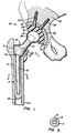
- Fig. 1 is a schematic, front elevation view through a human hip joint, illustrating the pelvis and the upper portion of the femur, and shows a prosthetic hip constructed in accordance with the present invention immediately after installation;
- Fig. 2 is a schematic front elevation view through a human hip joint illustrating an alternate embodiment of a prosthetic hip constructed in accordance with the present invention;
- Fig. 3 is a schematic front elevation view through a human hip joint illustrating a further embodiment of a resurface femoral head component making the 70° inclination concave rather than planar;
- Fig. 4 is a schematic front elevation view of a prosthetic knee constructed in accordance with the present invention;
- Fig. 5 is a cross-sectional view taken through line 4-4 of Fig. 1;
- Fig. 6 is a cross-sectional view taken through line 5-5 of Fig. 2; and
- Fig. 7 is a cross-sectional view taken through line 6-6 of Fig. 3.
-
- Referring to Fig. 1, a total prosthetic hip constructed in accordance with the present invention is made up of a femoral implant 1A and an acetabular implant 1B. The femoral implant includes a trochanteric body piece 2 which has a
porous surface 22 over the portion of its exterior which is intended to be directly affixed to the natural bone. To achieve the desired bony ingrowth, pores of the porous surface are preferably sized in a range between about 250-450 µ. The exact dimensioning of the pores is known to those skilled in the art and is not particularly critical. Also included is an anchor 4 which is comprised of apermanent core 8 and aresorbable sleeve 6.Core 8 is preferably made of a metal alloy such as titanium-6-aluminum-4-vanadium. - Outer
resorbable sleeve 6 is formed of a biodegradable material, for example, high molecular weight poly-L-lactic acid (PLLA) polymers. Other such materials include calcium hydroxyapatite, tricalcium phosphate and the compounds previously mentioned. - In a preferred embodiment, anchor 4 is affixed to trochanteric body piece 2 by means of a taper lock 10. Preferably anchor 4 includes a female portion and trochanteric body piece 2 includes a male portion of taper lock 10. The male and female portions have cooperating surfaces which are tapered at an angle selected so that they become effectively permanently secured to each other when the two portions are firmly pushed together. The female portion is preferably formed in anchor 4 so as to prevent formation of stress concentrations in the trochanteric body piece 2. The interconnection between trochanteric body 2 and anchor 4 is typically in the region of anchor 4 which straightens out in a lateral plane, although it may be located at other sites along anchor 4.
- This modular construction of the femoral implant 1A makes it possible to stock an inventory of differently shaped and/or sized components that can be assembled to fit any given patient. Thus, resorbable
outer sleeve 6 has multiple outer diameter sizes to fit different medullary shaft diameters whileinner core 8 has a constant diameter so that the outer diameter of anchor 4 varies with the thickness ofresorbable sleeve 6. In addition, the parts inventory will include anchors of varying lengths. Thus, the surgeon can select the permanent implant and the anchor which have the desired dimensions and shapes from the available inventory, assemble them with the above-discussed taper locks, and then install the implant in the patient. - In another embodiment the cross section of
inner core 8 of anchor 4 is not rounded, but, for example, a quadrilateral, e.g., square or rectangular. See Fig. 4. By extending the square cross section to taper lock 10 it is possible to predetermine the relative angular orientation of the modular components of the implant. Anchor 4 is inserted by press fitting into place. - Trochanteric body piece 2 is in continuity with a modular head or
ball 12, preferably formed of metal alloy such as a titanium alloy. Titanium-6-aluminum-4-vanadium is a preferred alloy. Other suitable alloys include cobalt-chromium and stainless steel. Trochanteric body piece 2 is connected to head 12 by a neck 13 which extends medially and upwardly with respect to trochanteric body piece 2.Head 12 cooperates with an acetabular cup 14 of the acetabular implant 1A. - In one embodiment, neck 13 forms a
taper lock 34 withhead 12 to secure the two to each other.Head 12 preferably has a female aperture which cooperates with a male extension of neck 13 to form thetaper lock 34. Alternatively, other locking means, such as a threaded screw arrangement (not separately illustrated), can be used. - The acetabular implant includes an
inner acetabular component 16 and anouter acetabular component 18.Inner component 16 is preferably formed of polyethylene although other noncorroding, nonresorbable high strength materials can be used.Outer acetabular component 18 is formed of titanium alloy although other high-strength materials, such as cobalt chromium alloy, stainless steel alloy and ceramics, can be used. The femoral head is preferably formed of zirconia. -
Inner acetabular component 16 is cup-shaped and has a concave surface facing and engagingball 12 of the femoral implant and permitting free movement of the ball in the socket.Outer acetabular component 18 includes multiple fixation holes, or alternatively a single bore, positioned so that upon implantation the bore is aligned with a pectineal line of the patient's pelvis as is described in greater detail in U.S. Patent No. 4,990,161. - Preferably,
resorbable screws 20 are used to secure acetabular cup 14 topelvic bone 35. Alternatively, the holes and bore can include a recess defining an inwardly facing shoulder that, upon implantation, engages a set screw having a threaded end extending into and engaging screw 20 (as is more fully described in U.S. Patent 4,990,161). The set screw is nonresorbable and acts as an interconnection betweenresorbable screw 20 and nonresorbableouter component 18. - The exterior surface of
outer component 18 in contact with the bone of the patient's pelvis and where stress transference is to take place has aporous surface 32 for anchorage of component to bone.Porous surface 32 promotes bone ingrowth into the area of load transfer between the pelvis and acetabular cup 14. To achieve the desired ingrowth, the pores are preferably sized in a range between about 250-450 µ. - Inner and outer
acetabular components 16/18 are held together by means known to the artisan. Typically, a lip is provided on one ofcomponents 16/18 and a keyarrangement locks components 16/18 together. -
Resorbable screw 20 has a first end including an external thread formed to cut into and firmly engage the bone structure. Resorbable screws 20 are typically 6.5mm in diameter. In a presently less preferred alternative, an opposite free end ofscrew 20 includes an internal thread which is engaged by a nonresorbable set screw. -
Screw 20 is preferably fabricated from a resorbable material such as modified or unmodified natural polymers, biodegradable ceramics, and other materials known to the artisan. The material is engineered to resorb at a predetermined time. For most applications, this time will coincide with a time period sufficient to allow mature bony attachment about acetabular component 14 for adequate mechanical fixation of the implant to the pelvis. - During implantation,
resorbable screw 20 is aligned with the bone of the natural acetabular cup.Screw 20 is tightened to firmly secure acetabular cup 14 to the bone. After implantation,inner component 16 may be positioned so that an overhangingportion 28 protrudes beyond the natural cup. This provides better seating of ball orhead 12 over a wider range of motion and helps prevent accidental dislocations of ball orhead 12 and the socket. - To implant the femoral implant 1A into a
femur 24, the head and neck offemur 24 are resected and an external femoral loading face is formed. The loading face is planar and generally perpendicular to a pectineal line and at an angle of approximately 70° to a longitudinal axis offemur 24. A cavity is shaped in the intertrochanteric aspect of the femur 5 by removing soft non-load bearing bone tissue which is mostly marrow. The entire intertrochanteric cavity may be broached slightly under size relative to the implant to achieve a secure press fit. - Trochanteric body 2 has a nonresorbable male taper lock depending therefrom. Prior to implantation, anchor 4 is connected to trochanteric body 2 by pressing a portion of taper lock 10 of body 2 into a reciprocating portion of taper lock 10 formed in anchor 4. Alternatively, this lock can be a screw connection.
- Trochanteric body 2, including anchor 4, is pressed into the appropriately dimensioned intertrochanteric upwardly opening cavity in
femur 24 until the internal and external loading surfaces firmly engage the bone. During the implantation process, elongated anchor 4 slides into the medullary canal of the femur and acts as a guide to prevent misalignment of trochanteric body 2 during the insertion. This is particularly important when substantial force must be applied to overcome the press fit between the body and the cavity. -
Resorbable sleeve 6 firmly engages the walls of the medullary canal with a press fit to secure and fix anchor 4 and trochanteric body 2 until bony ingrowth has attached body 2 to the patient's own femur. Innermetallic core 8 acts as a reinforcement to strengthen anchor 4 and prevent it from cracking, breaking or otherwise deforming. Aftersleeve 6 is totally resorbed,inner core 8 is essentially free floating within, that is, it does not contact the cortical walls of,medullary cavity 26 and it is sized such that it does not accept loads. - Once the implant is firmly fixed by bony attachment in its proper position, the function of anchor 4 is over and its functional portion,
sleeve 6, is eliminated by resorption. The final result is a functionally stemless femoral component that allows a near perfect physiologic transference of stresses to the proximal femur as opposed to a stemmed implant which is fixed distally. Distal fixation, as encountered with permanent stems which remain in contact with cortical bone, creates a potential for stress shielding and bone resorption proximally with an increased chance of mechanical failure. - After implantation, after proximal bony attachment and after resorption of
outer sleeve 6, there is no significant distal loading on the bone. This is the normal physiologic and anatomic situation. The absence of such distal loading about the femoral cortex adjacent to anchor 4 coupled with the transfer of loading and stresses proximally assures that the femoral implant is top loaded in a manner analogous to the normal femur in a healthy hip joint. - Fig. 2 illustrates an alternative embodiment of the femoral implant of the present invention. It comprises a resurface
femoral head implant 36 having ananchor 38.Anchor 38 includes aresorbable sleeve 44 surrounding a nonresorbableinner core 46. Resurfacecomponent 36 is formed of a nonresorbable material, preferably a metal alloy.Implant 36 defines a generallysemi-spherical head 37 which is shaped to fit into and cooperate with anacetabular cup 56 upon implantation. The surgeon selectsimplant 36 from an inventory of several, perhaps 4 or 5, sizes varying from small to large. - Resurface
component 36 is placed in contact with a patient's transectedfemoral head 64. This transection across the femoral head should be inclined approximately 70° to the longitudinal axis of the femur so that the applied loading forces act substantially perpendicular to the implant surface. Consequently, substantially only compressive forces are generated between the implant and the femur with theoretical enhancement and earlier bony attachment over the exterior load transferring implant surface. This 70° inclination being perpendicular to the implant surface would tend to enhance stabilization of the implant following resorption of the resorbable sleeve. Resurfaceimplant 36 protrudes from the generally planar surface of a partially resectedfemoral head 64. Aporous surface 66 is defined by a portion of the implant which is in intimate contact with the transectedfemur head 64.Porous surface 66 promotes bony attachment of the implant to the femur. - Fig. 3 is an illustration of a further embodiment of a resurface femoral head component making the 70° inclination concave rather than planar, thus affording greater stability of the implant. Thus, surface 66a is curved instead of being substantially planar.
-
Core 46 is preferably formed as one piece withhead 37. Alternatively,core 36 can be secured to resurfacecomponent 36 by any number of means known in the art, e.g., with the above-described taper lock or with a threaded connection.Anchor 38 extends in a lateral and downward direction with respect tohead 37. That is, a lower or distal surface ofimplant 36 which contacts partially resectedfemoral head 64 is placed at approximately a 70° cut angle with a longitudinal axis offemur 24. -
Anchor 38 is seated tightly intointramedullary canal 26 with a press-fit.Resorbable sleeve 44 may be tapered and dimensioned to interface the breached bone canal. A cross-sectional view of eitheranchor 38 shows a quadrilateral inner core cross section, most preferably of a square or rectangular shape. See Fig. 5. -
Anchor 38 is preferably also of modular construction as described above so that the size appropriate for a given patient can be selected from an inventory of differently sized and/or shaped anchors. The modules are connected just prior to implantation with a taper lock, for example. For optimal efficiency, the inventory consists of a select number ofcores 46 of equal diameter but differing lengths and a number ofresorbable sleeves 44, all having the same inner diameter so that they fit snugly onto any of the cores but of different outer diameter so that they can be press-fit into medullary canals of varying diameters. The optimal length of the combined core and sleeve would be such that it would contact the lateral cortical wall of the femur distal to the greater trochanter and opposite the lesser trochanter thus further stabilizing the implant. - Finally, the sleeves will have a sufficient length so that they can be fitted onto the largest core. For shorter cores, the sleeve is cut to the appropriate length just prior to assembly and installation.
-
Acetabular cup 56 is constructed as described above and includes anouter component 58 and aninner component 60. The outer component is usually formed of a metal alloy, such as a titanium alloy.Inner component 60 is preferably formed of polyethylene. Other materials are suitable as discussed above. Theouter component 58 is provided with aporous surface 52 as well as possibly being coated with calcium phosphate to direct and encourage bony attachment as previously discussed. - Outer and
inner components 58/60 are held together by means known in the art as discussed above. Resorbable screws 54 holdouter component 58 topelvic bone 35 until bony attachment occurs. Resorbable screws 54 are typically 6.5mm in diameter. - Turning now to Fig. 4, a total knee prosthesis constructed in accordance with the present invention is shown. The prosthesis includes a
femoral component 70 and atibial component 90.Femoral component 70 includes astem 74 having a resorbableouter sleeve 76 and aninner nonresorbable core 78.Inner core 78 is typically formed of a metal alloy such as a titanium alloy, preferably titanium-6-aluminum-4-vanadium. The stem can be of a modular construction as previously described. A cross-sectional view ofstem 74 shows a quadrilateral-shaped core dimension as previously discussed. See Fig. 6. -
Femoral component 70 also includes an articular bearing surface which is preferably formed of a metal alloy. A selected portion ofarticular bearing component 72 to be in contact with the natural femur has aporous surface 84 for bony attachment.Articular bearing component 72 terminates proximally in a portion of a lock, preferably ataper lock 80. Alternatively a screw-type lock may be utilized. - The portion of
taper lock 80 offemoral component 72 is preferably a female portion. Taper lock 80 is designed to cooperate with a distal termination ofstem 74 which includes an opposite cooperating portion oflock 80, preferably a male portion oftaper lock 80. -
Tibial component 90 includes astem 92 which is comprised of aninner nonresorbable core 96 and a resorbableouter sleeve 94.Inner core 96 is formed of a metal alloy. A preferred alloy is titanium-6-aluminum-4-vanadium although other alloys, such as cobalt-chromium or stainless steel, can be used. Resorbableouter sleeve 94 is again preferably of modular construction as isinner metal core 96.Inner metal core 96 preferably has a cross-section which is quadrilateral in shape, preferably square or rectangular, to reduce possible slippage or torsion. -
Inner metal core 96 terminates proximally in a portion of ataper lock 98, preferably a male portion which cooperates with a female termination of atibial tray component 88.Tibial tray 88 is nonresorbable and is preferably formed of a metal alloy such as titanium-6-aluminum-4-vanadium. At a lower or distal surface oftibial tray 88, there is aporous surface 82 for the desired bony attachment. - Proximal to
tibial tray 88 is a bearingcomponent 86 which can be made of polyethylene, ceramic or even a metal alloy.Bearing component 86 is in contact at its lower or distal surface with an upper or proximal surface oftibial tray 88. -
Bearing component 86 andtibial tray 88 are held together by means well known to the artisan. Usually, one oftibial tray 88 or bearingcomponent 86 is provided with a lip. A key arrangement locks the two components together. Resorbable screws 100 anchortibial tray 88 to the patient's tibia until bony attachment into the lower surface oftibial tray 88 assures bony fixation. -
Bearing component 86 is configured at its upper or proximal surface with two cup-shaped or concave portions designed to cooperate withfemoral component 72.Femoral component 72 is provided at its lower or distal surface with projections which are convex and cooperating to adapt with the configuration of bearingcomponent 86. This arrangement is in imitation of the natural human knee joint. That is, the femoral projections offemoral component 72 represent and mimic the femoral condyles and the upper or proximal surface of bearingcomponent 86 is shaped to mimic the articulating surface of the proximal tibia. - In installation,
femoral implant 70 is inserted into the patient's femoral medullary cavity after resection of the distal femur. Resected portions include the articulating surfaces.Femoral implant 70 is inserted after opening of a cavity in the femoral shaft.Femoral stem component 70 acts as an alignment and anchoring mechanism for the artificial joint. - In similar fashion, an appropriately dimensioned area in the tibial medullary shaft is opened. After appropriate resection of the proximal tibial area including the articulating surface,
tibial component 90 is placed into the opening in the patient's tibial medullary shaft.Tibial stem component 90 acts as an alignment and anchoring mechanism for the artificial knee joint. - Femoral
articular bearing component 72 has aporous surface 84 which is in intimate contact with the transected natural femur. Similarly, theporous surface 82 oftibial tray component 88 is in intimate contact with the transected natural tibia.Porous surfaces 84/82 permit and direct bony ingrowth into the prosthetic devices to permanently anchor them. After bony attachment has occurred, the resorbable materials, includingsleeve 76 offemoral implant 70 andsleeve 94 oftibial implant 90, resorb over a predetermined time period. - After resorption of
sleeves 76/94, remaininginner cores 78/96 are nonfunctional. That is, they are dimensioned such that they do not contact the bony cortices, thereby accepting no load bearing. Thus, the cores are essentially free floating within the medullary canal. As a consequence, no significant abnormal stress transference occurs, in contrast to conventional, non-resorbing stemmed devices. - Although hip and knee replacement have been described with particularity, the present invention is not so limited. Resorbable anchoring devices including a resorbable sleeve reinforced by an inner nonresorbable strengthening core are applicable to all joints including wrist, finger, elbow, ankle, foot, toe and shoulder. The artisan may readily appreciate other uses and variations of the present invention. The invention is not to be limited by the aforementioned examples but rather by the scope of the claims which follow.
Claims (8)
- An implant for a bone joint including:a component (1A, 36, 70, 90) defining an operative portion of the joint, the component having an interface facing generally away from the joint and adapted to be placed into intimate contact with an actual bone to which the component is to be fixed; andan anchor (4, 38, 74, 92) connected to the component (A1, 36, 70,90) and adapted to be inserted in a cavity in the bone for orienting and immovably fixing the component to the bone immediately upon implantation, the anchor being constructed of a high strength, permanent core (8, 46, 78, 96) and an outer layer (6, 44, 76, 94), the outer layer (6, 44, 76, 94) being 44, 76, 94), the outer layer (6, 44, 76, 94) being securely engages the walls of the cavity in the bone and, immediately after implantation, immovably secures the implant to the bone, characterized in that at least part of said interface includes means promoting bony ingrowth when the interface is in intimate contact with the natural bone, the permanent core is shaped so that its surfaces are sufficiently spaced from walls of the cavity after the implantation of the implant to prevent subsequent bone growth from reaching the core, the layer is constructed of biodegradable material so that it completely resorbs after a period of time and thereby completely vacates the portion of the cavity occupied by it following implantation; whereby, after the layer has resorbed, the core of the anchor is spaced from and out of contact with the walls defining the cavity so that substantially no load transference between the walls defining the cavity and the core can take place.
- The implant according to claim 1 characterized in that the component (1A, 36, 70) comprises a convex surface adapted to cooperate with a concave surface of another joint member (56, 90).
- The implant according to claim 1 characterized in that the outer layer (6, 44, 76, 94) is removably connected to the core (8, 46, 78, 96) to enable the selection of the outer layer from a supply of differently formed outer layers and thereby fit the outer layer to the shape of the cavity.
- The implant according to claim 1 characterized in that a cross sectional area of the core (8, 46, 78, 96) is quadrilateral.
- The implant according to claim 1 characterized in that the component (1A, 70, 90) has:a permanent, articulating implant component having a surface to contact the bone (22, 66, 82, 84) and a surface to interact with a cooperating surface of a joint; and a securing means (10, 80) for joining the articulating implant component to the core.
- The implant according to claim 5 characterized in that the securing means comprises a taper lock (10, 80).
- The implant according to claim 1 characterized in that the core (8, 46, 78, 96) is formed of a metal alloy selected from a group consisting of titanium-6-aluminium-4-vanadium, cobalt-chromium, and stainless steel.
- The implant according to claim 1 characterized in that the outer layer (6, 44, 76, 94) is formed from a material selected from a group consisting of polymers of glycolic acid, poymers of lactic acid, polyamides of α-amino acids, polylactic acid, polyglycolic acid, polylactic acid-polyglycolic acid copolymers, polyetheretherketone (PEEK), polyorthoester, polycarbonate, unmodified polymers, modified polymers, calcium phosphate, calcium hydroxyapatite and tricalcium phosphate.
Applications Claiming Priority (5)
| Application Number | Priority Date | Filing Date | Title |
|---|---|---|---|
| US897197 | 1986-08-18 | ||
| US85009192A | 1992-03-12 | 1992-03-12 | |
| US850091 | 1992-03-12 | ||
| US07/897,197 US5571193A (en) | 1992-03-12 | 1992-06-11 | Implant with reinforced resorbable stem |
| PCT/US1993/001463 WO1993017639A1 (en) | 1992-03-12 | 1993-02-18 | Implant with reinforced resorbable stem |
Publications (3)
| Publication Number | Publication Date |
|---|---|
| EP0630218A1 EP0630218A1 (en) | 1994-12-28 |
| EP0630218A4 EP0630218A4 (en) | 1995-04-19 |
| EP0630218B1 true EP0630218B1 (en) | 2000-05-03 |
Family
ID=27126901
Family Applications (1)
| Application Number | Title | Priority Date | Filing Date |
|---|---|---|---|
| EP93906067A Expired - Lifetime EP0630218B1 (en) | 1992-03-12 | 1993-02-18 | Implant with reinforced resorbable stem |
Country Status (8)
| Country | Link |
|---|---|
| US (3) | US5571193A (en) |
| EP (1) | EP0630218B1 (en) |
| JP (1) | JPH07506739A (en) |
| AT (1) | ATE192313T1 (en) |
| AU (1) | AU668380B2 (en) |
| CA (1) | CA2131541C (en) |
| DE (1) | DE69328552D1 (en) |
| WO (1) | WO1993017639A1 (en) |
Cited By (1)
| Publication number | Priority date | Publication date | Assignee | Title |
|---|---|---|---|---|
| KR20200141441A (en) * | 2018-03-07 | 2020-12-18 | 코싱턴 리미티드 | Temporary spacer device for human joints |
Families Citing this family (107)
| Publication number | Priority date | Publication date | Assignee | Title |
|---|---|---|---|---|
| FR2720627B1 (en) * | 1994-06-06 | 1996-10-31 | Jacques Hummer | Orthopedic fixation element. |
| DE19530531C2 (en) * | 1995-08-19 | 1997-08-07 | Frank Dr Med Lampe | Hip joint endoprosthesis with bioresorbable, axially supported middle part |
| EP0761242A1 (en) * | 1995-08-21 | 1997-03-12 | Bristol-Myers Squibb Company | Orthopaedic implant with bearing surface |
| US5782930A (en) * | 1996-02-13 | 1998-07-21 | Hommedica Inc. | Polyetheretherketone (PEEK) retaining ring for an acetabular cup assembly |
| GB9623540D0 (en) * | 1996-11-12 | 1997-01-08 | Johnson & Johnson Professional | Hip joint prosthesis |
| US5755810A (en) * | 1996-11-13 | 1998-05-26 | Cunningham; Robert A. | Hip implant prosthesis |
| US5880976A (en) * | 1997-02-21 | 1999-03-09 | Carnegie Mellon University | Apparatus and method for facilitating the implantation of artificial components in joints |
| US6205411B1 (en) | 1997-02-21 | 2001-03-20 | Carnegie Mellon University | Computer-assisted surgery planner and intra-operative guidance system |
| DE19755536A1 (en) * | 1997-12-13 | 1999-06-17 | Ceramtec Ag | Acetabular cup |
| US6156070A (en) * | 1999-03-26 | 2000-12-05 | Howmedica Osteonics Corp. | Allograft prosthetic joints and method |
| US6228121B1 (en) | 1999-06-21 | 2001-05-08 | Depuy Othopedics, Inc. | Prosthesis system and method of implanting |
| US6187008B1 (en) | 1999-07-07 | 2001-02-13 | Bristol-Myers Squibb | Device for temporarily fixing bones |
| US7635390B1 (en) * | 2000-01-14 | 2009-12-22 | Marctec, Llc | Joint replacement component having a modular articulating surface |
| US8114163B2 (en) * | 2000-04-10 | 2012-02-14 | Biomet Manufacturing Corp. | Method and apparatus for adjusting height and angle for a radial head |
| US8920509B2 (en) | 2000-04-10 | 2014-12-30 | Biomet Manufacturing, Llc | Modular radial head prosthesis |
| US8535382B2 (en) | 2000-04-10 | 2013-09-17 | Biomet Manufacturing, Llc | Modular radial head prostheses |
| AU2001280610A1 (en) * | 2000-07-31 | 2002-02-13 | Massachusetts General Hospital | Improved acetabular components providing greater range of motion |
| US6913623B1 (en) | 2000-08-15 | 2005-07-05 | Centerpulse Orthopedics, Inc. | Two piecefused femoral hip stem |
| US6652591B2 (en) | 2000-12-14 | 2003-11-25 | Depuy Orthopaedics, Inc. | Prosthesis with feature aligned to trabeculae |
| US6620197B2 (en) | 2001-01-23 | 2003-09-16 | Depuy Orthopaedics, Inc. | Method and apparatus for performing a shoulder replacement procedure in the treatment of cuff tear arthropathy |
| US8123814B2 (en) | 2001-02-23 | 2012-02-28 | Biomet Manufacturing Corp. | Method and appartus for acetabular reconstruction |
| US7597715B2 (en) * | 2005-04-21 | 2009-10-06 | Biomet Manufacturing Corp. | Method and apparatus for use of porous implants |
| DE50209814D1 (en) * | 2001-05-18 | 2007-05-10 | Copf Peter | Cementless hip joint endoprosthesis as a surface replacement of the proximal femur |
| US7261741B2 (en) * | 2001-06-30 | 2007-08-28 | Depuy Products, Inc. | Prosthesis with resorbable collar |
| GB0116341D0 (en) | 2001-07-04 | 2001-08-29 | Smith & Nephew | Biodegradable polymer systems |
| EP1416866A4 (en) * | 2001-07-16 | 2007-04-18 | Depuy Products Inc | Devices form naturally occurring biologically derived |
| US6749639B2 (en) | 2001-08-27 | 2004-06-15 | Mayo Foundation For Medical Education And Research | Coated prosthetic implant |
| ITRM20010628A1 (en) * | 2001-10-23 | 2003-04-23 | Univ Roma | HIP PROSTHESIS AND RELATED METHOD OF DESIGN. |
| US6709462B2 (en) | 2002-01-11 | 2004-03-23 | Mayo Foundation For Medical Education And Research | Acetabular shell with screw access channels |
| GB0202233D0 (en) | 2002-01-31 | 2002-03-20 | Smith & Nephew | Bioresorbable polymers |
| GB0207170D0 (en) | 2002-03-26 | 2002-05-08 | Mcminn Derek J W | Hip joint prosthesis |
| US6923833B2 (en) * | 2002-04-09 | 2005-08-02 | Ray C. Wasielewski | Biologically reabsorbable acetabular constraining components and materials for use with a hip replacement prosthesis and bioreabsorbable materials to augment hip replacement stability and function |
| US6981991B2 (en) * | 2002-06-27 | 2006-01-03 | Ferree Bret A | Arthroplasty devices configured to reduce shear stress |
| US20040078081A1 (en) * | 2002-09-09 | 2004-04-22 | Ferree Bret A. | Bioresorbable components and methods for spinal arthroplasty |
| US20040083004A1 (en) * | 2002-10-23 | 2004-04-29 | Wasielewski Ray C. | Use of snap-on semiannular augments to inhibit multi-directional instability after total hip arthroplasty |
| US7309361B2 (en) * | 2002-10-23 | 2007-12-18 | Wasielewski Ray C | Biologic modular tibial and femoral component augments for use with total knee arthroplasty |
| US6926740B2 (en) | 2002-12-13 | 2005-08-09 | Depuy Products, Inc. | Modular orthopaedic implant apparatus and method |
| US7338498B2 (en) * | 2003-03-31 | 2008-03-04 | Depuy Products, Inc. | Prosthetic implant, trial and associated method |
| US8366713B2 (en) | 2003-03-31 | 2013-02-05 | Depuy Products, Inc. | Arthroplasty instruments and associated method |
| US8105327B2 (en) | 2003-03-31 | 2012-01-31 | Depuy Products, Inc. | Punch, implant and associated method |
| US20040193278A1 (en) * | 2003-03-31 | 2004-09-30 | Maroney Brian J. | Articulating surface replacement prosthesis |
| US8545506B2 (en) * | 2003-03-31 | 2013-10-01 | DePuy Synthes Products, LLC | Cutting guide for use with an extended articulation orthopaedic implant |
| US7527631B2 (en) * | 2003-03-31 | 2009-05-05 | Depuy Products, Inc. | Arthroplasty sizing gauge |
| US7517364B2 (en) | 2003-03-31 | 2009-04-14 | Depuy Products, Inc. | Extended articulation orthopaedic implant and associated method |
| US20040193276A1 (en) * | 2003-03-31 | 2004-09-30 | Maroney Brian J. | Modular articulating surface replacement prosthesis |
| GB0317192D0 (en) * | 2003-07-19 | 2003-08-27 | Smith & Nephew | High strength bioresorbable co-polymers |
| US7699879B2 (en) * | 2003-10-21 | 2010-04-20 | Warsaw Orthopedic, Inc. | Apparatus and method for providing dynamizable translations to orthopedic implants |
| US20050085814A1 (en) * | 2003-10-21 | 2005-04-21 | Sherman Michael C. | Dynamizable orthopedic implants and their use in treating bone defects |
| US20050136764A1 (en) * | 2003-12-18 | 2005-06-23 | Sherman Michael C. | Designed composite degradation for spinal implants |
| GB0329654D0 (en) | 2003-12-23 | 2004-01-28 | Smith & Nephew | Tunable segmented polyacetal |
| US7879042B2 (en) * | 2004-03-05 | 2011-02-01 | Depuy Products, Inc. | Surface replacement extractor device and associated method |
| WO2005117763A2 (en) * | 2004-05-28 | 2005-12-15 | Smith & Nephew, Inc. | Fluted intramedullary stem |
| US7892290B2 (en) * | 2004-05-28 | 2011-02-22 | Smith & Nephew, Inc. | Fluted sleeve hip prosthesis for modular stem |
| KR20070056050A (en) * | 2004-07-01 | 2007-05-31 | 오소플랜 피티와이 엘티디 | Hip resurfacing component |
| US20060129148A1 (en) * | 2004-10-01 | 2006-06-15 | Simmons Edward D | Screw sleeve made of polyetheretherketone (PEEK) for augmentation of bone screw insertion in osteoporotic or revision lumbar spine instrumentation |
| US9452001B2 (en) * | 2005-02-22 | 2016-09-27 | Tecres S.P.A. | Disposable device for treatment of infections of human limbs |
| ITVI20050049A1 (en) * | 2005-02-22 | 2006-08-23 | Tecres Spa | DISPOSABLE DEVICE FOR THE TREATMENT OF INFECTION OF ARTS OF THE HUMAN BODY, PARTICULARLY OF ARTS WITH LONG BONES |
| US7474223B2 (en) * | 2005-04-18 | 2009-01-06 | Warsaw Orthopedic, Inc. | Method and apparatus for implant identification |
| US8266780B2 (en) * | 2005-04-21 | 2012-09-18 | Biomet Manufacturing Corp. | Method and apparatus for use of porous implants |
| US8066778B2 (en) * | 2005-04-21 | 2011-11-29 | Biomet Manufacturing Corp. | Porous metal cup with cobalt bearing surface |
| US8292967B2 (en) * | 2005-04-21 | 2012-10-23 | Biomet Manufacturing Corp. | Method and apparatus for use of porous implants |
| US8021432B2 (en) | 2005-12-05 | 2011-09-20 | Biomet Manufacturing Corp. | Apparatus for use of porous implants |
| US7976580B2 (en) * | 2005-08-18 | 2011-07-12 | Mayo Foundation For Medical Education And Research | Semi-constrained 1st carpometacarpal implant arthroplasty and method |
| CA2625264C (en) | 2005-10-13 | 2015-12-15 | Synthes (U.S.A.) | Drug-impregnated sleeve for a medical implant |
| GB2432318A (en) * | 2005-11-18 | 2007-05-23 | Corin Ltd | Resurfacing femoral head component |
| US7635447B2 (en) * | 2006-02-17 | 2009-12-22 | Biomet Manufacturing Corp. | Method and apparatus for forming porous metal implants |
| US20080015691A1 (en) | 2006-06-15 | 2008-01-17 | Depuy Products, Inc. | Orthopaedic implants having bioresorbable posts |
| WO2008005941A2 (en) * | 2006-06-30 | 2008-01-10 | Hodge Biomotion Technologies, Llc | Precision acetabular machining system and resurfacing acetabular implant |
| US20080053169A1 (en) * | 2006-08-30 | 2008-03-06 | Victoria Marie Ricker | Theft deterrent device for bags |
| CA2679365C (en) | 2006-11-30 | 2016-05-03 | Smith & Nephew, Inc. | Fiber reinforced composite material |
| CN101199870B (en) * | 2006-12-15 | 2010-05-19 | 上海杰事杰新材料股份有限公司 | Hydroxyl apatite/nylon nanometer artificial bone preparing method |
| US8562616B2 (en) | 2007-10-10 | 2013-10-22 | Biomet Manufacturing, Llc | Knee joint prosthesis system and method for implantation |
| US8187280B2 (en) | 2007-10-10 | 2012-05-29 | Biomet Manufacturing Corp. | Knee joint prosthesis system and method for implantation |
| US8157869B2 (en) | 2007-01-10 | 2012-04-17 | Biomet Manufacturing Corp. | Knee joint prosthesis system and method for implantation |
| US8163028B2 (en) | 2007-01-10 | 2012-04-24 | Biomet Manufacturing Corp. | Knee joint prosthesis system and method for implantation |
| US8328873B2 (en) | 2007-01-10 | 2012-12-11 | Biomet Manufacturing Corp. | Knee joint prosthesis system and method for implantation |
| US20080195221A1 (en) * | 2007-01-22 | 2008-08-14 | Zimmer Gmbh | Implant and a method for partial replacement of joint surfaces |
| US7909883B2 (en) * | 2007-02-21 | 2011-03-22 | Sidebotham Christopher G | Percutaneous implant for limb salvage |
| US9370427B2 (en) * | 2007-04-13 | 2016-06-21 | Christopher G. Sidebotham | Bone-compliant femoral stem |
| JP5416090B2 (en) * | 2007-04-18 | 2014-02-12 | スミス アンド ネフュー ピーエルシー | Expansion molding of shape memory polymer |
| US9000066B2 (en) * | 2007-04-19 | 2015-04-07 | Smith & Nephew, Inc. | Multi-modal shape memory polymers |
| DE602008006181D1 (en) * | 2007-04-19 | 2011-05-26 | Smith & Nephew Inc | GRAFT FIXATION |
| JP5205462B2 (en) * | 2007-09-25 | 2013-06-05 | バイオメット・マニュファクチャリング・コーポレイション | Cementless tibial tray |
| US9539097B2 (en) | 2007-11-08 | 2017-01-10 | Linares Medical Devices, Llc | Hip and knee joint assemblies incorporating debris collection architecture between the ball and seat interface |
| US8979938B2 (en) * | 2007-11-08 | 2015-03-17 | Linares Medical Devices, Llc | Artificial knee implant including liquid ballast supporting / rotating surfaces and incorporating flexible multi-material and natural lubricant retaining matrix applied to a joint surface |
| US8764837B2 (en) * | 2008-03-26 | 2014-07-01 | Linares Medical Devices, Llc | Reinforced joint assembly |
| US8828088B2 (en) * | 2007-11-08 | 2014-09-09 | Linares Medical Devices, Llc | Joint assembly incorporating undercut surface design to entrap accumulating wear debris from plastic joint assembly |
| US8702801B2 (en) * | 2008-02-25 | 2014-04-22 | Linares Medical Devices, Llc | Artificial wear resistant plug for mounting to existing joint bone |
| US7988736B2 (en) * | 2008-02-27 | 2011-08-02 | Biomet Manufacturing Corp. | Method and apparatus for providing resorbable fixation of press-fit implants |
| US8123815B2 (en) | 2008-11-24 | 2012-02-28 | Biomet Manufacturing Corp. | Multiple bearing acetabular prosthesis |
| JP5603345B2 (en) * | 2008-12-02 | 2014-10-08 | スミス アンド ネフュー インコーポレーテッド | Iliac canal prosthesis |
| US8556972B2 (en) * | 2009-04-02 | 2013-10-15 | Sevika Holding AG | Monolithic orthopedic implant with an articular finished surface |
| US20100256758A1 (en) * | 2009-04-02 | 2010-10-07 | Synvasive Technology, Inc. | Monolithic orthopedic implant with an articular finished surface |
| US20100262244A1 (en) * | 2009-04-14 | 2010-10-14 | Warsaw Orthopedic, Inc. | Metal Coated Implant |
| US8308810B2 (en) | 2009-07-14 | 2012-11-13 | Biomet Manufacturing Corp. | Multiple bearing acetabular prosthesis |
| US8444699B2 (en) | 2010-02-18 | 2013-05-21 | Biomet Manufacturing Corp. | Method and apparatus for augmenting bone defects |
| US8926705B2 (en) | 2010-05-10 | 2015-01-06 | Linares Medical Devices, Llc | Implantable joint assembly featuring debris entrapment chamber subassemblies along with opposing magnetic fields generated between articulating implant components in order to minimize frictional force and associated wear |
| TWI590843B (en) | 2011-12-28 | 2017-07-11 | 信迪思有限公司 | Films and methods of manufacture |
| CN105555328B (en) | 2013-06-21 | 2019-01-11 | 德普伊新特斯产品公司 | film and manufacturing method |
| BR202014024100U2 (en) * | 2014-09-29 | 2020-02-27 | Universidade Federal Do Rio Grande Do Sul | FEMORAL ISOELASTIC STEM MADE IN POLYMER |
| CN105031745B (en) * | 2015-05-08 | 2018-10-19 | 上海起励生物技术服务中心 | A kind of orthopaedics implant with polymer wrapped metal prostheses |
| CN105030380A (en) * | 2015-05-15 | 2015-11-11 | 江苏奥康尼医疗科技发展有限公司 | Combined artificial hip joint cup |
| JP2020523124A (en) * | 2017-06-14 | 2020-08-06 | エボニック オペレーションズ ゲーエムベーハー | Polymer sleeves and their fabrication and processing to prevent stem wear and improve taper lock in modular and non-modular orthopedic implants |
| CN107899083B (en) * | 2017-11-29 | 2020-05-26 | 南宁越洋科技有限公司 | Preparation method of super-wear-resistant high-toughness bioactive artificial hip joint |
| CN108143520A (en) * | 2017-12-21 | 2018-06-12 | 嘉思特华剑医疗器材(天津)有限公司 | A kind of minimally invasive hip prosthesis system |
| CN110496246B (en) * | 2019-09-09 | 2021-12-14 | 广州飞胜智能科技股份有限公司 | Bone repair material constructed by 3D printing and preparation method |
| AU2021200320A1 (en) * | 2020-01-22 | 2021-08-05 | Howmedica Osteonics Corp. | Femoral implant |
Citations (1)
| Publication number | Priority date | Publication date | Assignee | Title |
|---|---|---|---|---|
| US4990161A (en) * | 1984-03-16 | 1991-02-05 | Kampner Stanley L | Implant with resorbable stem |
Family Cites Families (34)
| Publication number | Priority date | Publication date | Assignee | Title |
|---|---|---|---|---|
| US2112007A (en) * | 1937-01-16 | 1938-03-22 | Pinkney B Adams | Anchoring means for false teeth |
| US3463158A (en) * | 1963-10-31 | 1969-08-26 | American Cyanamid Co | Polyglycolic acid prosthetic devices |
| US3543749A (en) * | 1968-02-19 | 1970-12-01 | Ned M Grove | Mechanical pseudarthrosis of the femur |
| US3623164A (en) * | 1969-10-06 | 1971-11-30 | Gulf Oil Corp | Prosthetic device |
| US3787900A (en) * | 1971-06-09 | 1974-01-29 | Univ Iowa State Res Found | Artificial bone or tooth prosthesis material |
| DE2242867C3 (en) * | 1972-08-31 | 1975-09-25 | Battelle-Institut E.V., 6000 Frankfurt | Process for the production of implantable, ceramic bone replacement, bone composite or prosthesis anchoring materials |
| CA974148A (en) * | 1973-02-06 | 1975-09-09 | Clark Equipment Company | Tree harvester |
| US3929971A (en) * | 1973-03-30 | 1975-12-30 | Research Corp | Porous biomaterials and method of making same |
| US3840904A (en) * | 1973-04-30 | 1974-10-15 | R Tronzo | Acetabular cup prosthesis |
| FR2295729A1 (en) * | 1974-12-27 | 1976-07-23 | Mahay Et Cie | TOTAL HIP PROSTHESIS |
| CH595293A5 (en) * | 1975-02-20 | 1978-02-15 | Battelle Memorial Institute | |
| FR2315902A1 (en) * | 1975-07-01 | 1977-01-28 | Ceraver | Metal rod as prosthetic insert into a bone shank - has longitudinal depressions filled with material promoting growth of bone cells |
| AT352867B (en) * | 1976-05-12 | 1979-10-10 | Battelle Institut E V | BONE REPLACEMENT, BONE COMPOUND OR PROSTHESIS ANCHORING MATERIAL AND PROCESS FOR ITS PRODUCTION |
| DE2620907C3 (en) * | 1976-05-12 | 1984-09-20 | Battelle-Institut E.V., 6000 Frankfurt | Anchoring for highly stressed endoprostheses |
| IL56141A (en) * | 1977-12-23 | 1981-10-30 | Sterling Drug Inc | Whitlockite ceramic and its manufacture |
| US4224696A (en) * | 1978-09-08 | 1980-09-30 | Hexcel Corporation | Prosthetic knee |
| FR2460657A1 (en) * | 1979-07-12 | 1981-01-30 | Anvar | BIODEGRADABLE IMPLANT FOR USE AS A BONE PROSTHESIS PIECE |
| EP0023787B1 (en) * | 1979-07-25 | 1983-07-20 | University Of Exeter | Plugs for the medullary canal of a bone |
| US4488391A (en) * | 1979-10-31 | 1984-12-18 | Joseph Pavnica | Centering clips for window frames |
| GB2072514B (en) * | 1980-03-27 | 1984-02-29 | Nat Res Dev | Orthopaedic implants |
| CH648197A5 (en) * | 1980-05-28 | 1985-03-15 | Synthes Ag | IMPLANT AND SCREW FASTENING ON ITS BONE. |
| DE3274519D1 (en) * | 1981-07-30 | 1987-01-15 | Ceraver | Prosthetic stem composed of titanium or its alloys for the cementless fixation in a long bone |
| US4840632A (en) * | 1984-03-16 | 1989-06-20 | Kampner Stanley L | Hip prosthesis |
| FR2619005B1 (en) * | 1987-08-03 | 1993-09-17 | Omci | HIP PROSTHESIS WITH INTERCHANGEABLE EPIPHYSIS |
| DE8716607U1 (en) * | 1987-12-14 | 1989-01-12 | Mecron Medizinische Produkte Gmbh, 1000 Berlin, De | |
| US4840623A (en) * | 1988-02-01 | 1989-06-20 | Fbk International Corporation | Medical catheter with splined internal wall |
| DE3811345C1 (en) * | 1988-04-02 | 1989-09-07 | Aesculap Ag, 7200 Tuttlingen, De | |
| US4983183A (en) * | 1989-02-06 | 1991-01-08 | Horowitz Stephen M | Hip prosthesis and method for implanting the same |
| US4995883A (en) * | 1989-02-08 | 1991-02-26 | Smith & Nephew Richards Inc. | Modular hip prosthesis |
| GB8903464D0 (en) * | 1989-02-15 | 1989-04-05 | Joint Replacement Instrumentat | Coated femoral prosthesis |
| US5074879A (en) * | 1990-10-26 | 1991-12-24 | Pappas Michael J | Prosthetic device with modular stem |
| GB9011132D0 (en) * | 1990-05-17 | 1990-07-04 | Howmedica | Phosthetic intramedullary femoral prosthesis with preformed sheath |
| CA2041430C (en) * | 1990-10-30 | 2002-11-26 | Jack Eldon Parr | Orthopaedic implant device |
| EP0523926A3 (en) * | 1991-07-15 | 1993-12-01 | Smith & Nephew Richards Inc | Prosthetic implants with bioabsorbable coating |
-
1992
- 1992-06-11 US US07/897,197 patent/US5571193A/en not_active Expired - Fee Related
-
1993
- 1993-02-18 CA CA002131541A patent/CA2131541C/en not_active Expired - Fee Related
- 1993-02-18 AT AT93906067T patent/ATE192313T1/en not_active IP Right Cessation
- 1993-02-18 DE DE69328552T patent/DE69328552D1/en not_active Expired - Lifetime
- 1993-02-18 EP EP93906067A patent/EP0630218B1/en not_active Expired - Lifetime
- 1993-02-18 WO PCT/US1993/001463 patent/WO1993017639A1/en active IP Right Grant
- 1993-02-18 JP JP5515700A patent/JPH07506739A/en active Pending
- 1993-02-18 AU AU37247/93A patent/AU668380B2/en not_active Ceased
-
1995
- 1995-10-04 US US08/539,038 patent/US5733338A/en not_active Expired - Lifetime
-
1997
- 1997-08-06 US US08/907,272 patent/US6013104A/en not_active Expired - Fee Related
Patent Citations (1)
| Publication number | Priority date | Publication date | Assignee | Title |
|---|---|---|---|---|
| US4990161A (en) * | 1984-03-16 | 1991-02-05 | Kampner Stanley L | Implant with resorbable stem |
Cited By (1)
| Publication number | Priority date | Publication date | Assignee | Title |
|---|---|---|---|---|
| KR20200141441A (en) * | 2018-03-07 | 2020-12-18 | 코싱턴 리미티드 | Temporary spacer device for human joints |
Also Published As
| Publication number | Publication date |
|---|---|
| WO1993017639A1 (en) | 1993-09-16 |
| AU668380B2 (en) | 1996-05-02 |
| CA2131541C (en) | 2001-05-29 |
| ATE192313T1 (en) | 2000-05-15 |
| AU3724793A (en) | 1993-10-05 |
| US6013104A (en) | 2000-01-11 |
| DE69328552D1 (en) | 2000-06-08 |
| JPH07506739A (en) | 1995-07-27 |
| EP0630218A1 (en) | 1994-12-28 |
| US5733338A (en) | 1998-03-31 |
| EP0630218A4 (en) | 1995-04-19 |
| CA2131541A1 (en) | 1993-09-16 |
| US5571193A (en) | 1996-11-05 |
Similar Documents
| Publication | Publication Date | Title |
|---|---|---|
| EP0630218B1 (en) | Implant with reinforced resorbable stem | |
| US4990161A (en) | Implant with resorbable stem | |
| US4840632A (en) | Hip prosthesis | |
| US11833052B2 (en) | Tissue integration design for seamless implant fixation | |
| US6749639B2 (en) | Coated prosthetic implant | |
| US6863690B2 (en) | Humeral shoulder prosthesis | |
| US4514865A (en) | Stemmed femoral component for the human hip | |
| US4406023A (en) | Stemmed femoral component for the human hip | |
| US8728168B2 (en) | Prosthetic implant support structure | |
| US4976740A (en) | Anchored femoral dome | |
| US7931691B2 (en) | External proximal femoral prosthesis for total hip arthroplasty | |
| WO2005117762A2 (en) | Canine femoral stem system | |
| EP1900344A2 (en) | Resurfacing femoral head component | |
| US6887278B2 (en) | Prosthetic implant having segmented flexible stem | |
| WO1996002213A1 (en) | Proximal conical stem | |
| CN100528104C (en) | Hip-joint prosthesis comprising a shaft that can be inserted into the femur | |
| US6071312A (en) | Endoprosthesis, in particular an artificial hip joint | |
| US6383226B1 (en) | Prostheses having curvilinear collars | |
| JP2990531B2 (en) | Hip prosthesis | |
| Zuckerman et al. | A review of the use of modularity in total shoulder arthroplasty | |
| EP1464304A2 (en) | Prosthetic device | |
| Munuera et al. | International Meeting on Total Hip Arthroplasty: Hospital La Paz-Madrid, April 6–8, 2000 | |
| Walcher | First Experience with the PM Prosthesis |
Legal Events
| Date | Code | Title | Description |
|---|---|---|---|
| PUAI | Public reference made under article 153(3) epc to a published international application that has entered the european phase |
Free format text: ORIGINAL CODE: 0009012 |
|
| 17P | Request for examination filed |
Effective date: 19941008 |
|
| AK | Designated contracting states |
Kind code of ref document: A1 Designated state(s): AT BE CH DE DK ES FR GB IE IT LI NL PT SE |
|
| A4 | Supplementary search report drawn up and despatched |
Effective date: 19950227 |
|
| AK | Designated contracting states |
Kind code of ref document: A4 Designated state(s): AT BE CH DE DK ES FR GB IE IT LI NL PT SE |
|
| 17Q | First examination report despatched |
Effective date: 19980916 |
|
| GRAG | Despatch of communication of intention to grant |
Free format text: ORIGINAL CODE: EPIDOS AGRA |
|
| GRAG | Despatch of communication of intention to grant |
Free format text: ORIGINAL CODE: EPIDOS AGRA |
|
| GRAH | Despatch of communication of intention to grant a patent |
Free format text: ORIGINAL CODE: EPIDOS IGRA |
|
| GRAH | Despatch of communication of intention to grant a patent |
Free format text: ORIGINAL CODE: EPIDOS IGRA |
|
| GRAA | (expected) grant |
Free format text: ORIGINAL CODE: 0009210 |
|
| AK | Designated contracting states |
Kind code of ref document: B1 Designated state(s): AT BE CH DE DK ES FR GB IE IT LI NL PT SE |
|
| PG25 | Lapsed in a contracting state [announced via postgrant information from national office to epo] |
Ref country code: NL Free format text: LAPSE BECAUSE OF FAILURE TO SUBMIT A TRANSLATION OF THE DESCRIPTION OR TO PAY THE FEE WITHIN THE PRESCRIBED TIME-LIMIT Effective date: 20000503 Ref country code: ES Free format text: THE PATENT HAS BEEN ANNULLED BY A DECISION OF A NATIONAL AUTHORITY Effective date: 20000503 Ref country code: BE Free format text: LAPSE BECAUSE OF FAILURE TO SUBMIT A TRANSLATION OF THE DESCRIPTION OR TO PAY THE FEE WITHIN THE PRESCRIBED TIME-LIMIT Effective date: 20000503 Ref country code: AT Free format text: LAPSE BECAUSE OF FAILURE TO SUBMIT A TRANSLATION OF THE DESCRIPTION OR TO PAY THE FEE WITHIN THE PRESCRIBED TIME-LIMIT Effective date: 20000503 |
|
| REF | Corresponds to: |
Ref document number: 192313 Country of ref document: AT Date of ref document: 20000515 Kind code of ref document: T |
|
| REG | Reference to a national code |
Ref country code: CH Ref legal event code: EP |
|
| REG | Reference to a national code |
Ref country code: IE Ref legal event code: FG4D |
|
| REF | Corresponds to: |
Ref document number: 69328552 Country of ref document: DE Date of ref document: 20000608 |
|
| ITF | It: translation for a ep patent filed |
Owner name: STUDIO TORTA S.R.L. |
|
| PG25 | Lapsed in a contracting state [announced via postgrant information from national office to epo] |
Ref country code: SE Free format text: LAPSE BECAUSE OF FAILURE TO SUBMIT A TRANSLATION OF THE DESCRIPTION OR TO PAY THE FEE WITHIN THE PRESCRIBED TIME-LIMIT Effective date: 20000803 Ref country code: PT Free format text: LAPSE BECAUSE OF FAILURE TO SUBMIT A TRANSLATION OF THE DESCRIPTION OR TO PAY THE FEE WITHIN THE PRESCRIBED TIME-LIMIT Effective date: 20000803 Ref country code: DK Free format text: LAPSE BECAUSE OF FAILURE TO SUBMIT A TRANSLATION OF THE DESCRIPTION OR TO PAY THE FEE WITHIN THE PRESCRIBED TIME-LIMIT Effective date: 20000803 |
|
| PG25 | Lapsed in a contracting state [announced via postgrant information from national office to epo] |
Ref country code: DE Free format text: LAPSE BECAUSE OF FAILURE TO SUBMIT A TRANSLATION OF THE DESCRIPTION OR TO PAY THE FEE WITHIN THE PRESCRIBED TIME-LIMIT Effective date: 20000804 |
|
| ET | Fr: translation filed | ||
| NLV1 | Nl: lapsed or annulled due to failure to fulfill the requirements of art. 29p and 29m of the patents act | ||
| REG | Reference to a national code |
Ref country code: CH Ref legal event code: PL |
|
| PGFP | Annual fee paid to national office [announced via postgrant information from national office to epo] |
Ref country code: IE Payment date: 20010228 Year of fee payment: 9 |
|
| PLBE | No opposition filed within time limit |
Free format text: ORIGINAL CODE: 0009261 |
|
| STAA | Information on the status of an ep patent application or granted ep patent |
Free format text: STATUS: NO OPPOSITION FILED WITHIN TIME LIMIT |
|
| REG | Reference to a national code |
Ref country code: CH Ref legal event code: NV Representative=s name: BUECHEL, VON REVY & PARTNER Ref country code: CH Ref legal event code: AEN Free format text: DAS PATENT IST AUFGRUND DES WEITERBEHANDLUNGSANTRAGS VOM 18.10.2000 REAKTIVIERT WORDEN. |
|
| 26N | No opposition filed | ||
| REG | Reference to a national code |
Ref country code: GB Ref legal event code: IF02 |
|
| PG25 | Lapsed in a contracting state [announced via postgrant information from national office to epo] |
Ref country code: IE Free format text: LAPSE BECAUSE OF NON-PAYMENT OF DUE FEES Effective date: 20020218 |
|
| REG | Reference to a national code |
Ref country code: IE Ref legal event code: MM4A |
|
| PGFP | Annual fee paid to national office [announced via postgrant information from national office to epo] |
Ref country code: FR Payment date: 20030131 Year of fee payment: 11 |
|
| PGFP | Annual fee paid to national office [announced via postgrant information from national office to epo] |
Ref country code: CH Payment date: 20030203 Year of fee payment: 11 |
|
| PGFP | Annual fee paid to national office [announced via postgrant information from national office to epo] |
Ref country code: GB Payment date: 20030212 Year of fee payment: 11 |
|
| PG25 | Lapsed in a contracting state [announced via postgrant information from national office to epo] |
Ref country code: GB Free format text: LAPSE BECAUSE OF NON-PAYMENT OF DUE FEES Effective date: 20040218 |
|
| PG25 | Lapsed in a contracting state [announced via postgrant information from national office to epo] |
Ref country code: LI Free format text: LAPSE BECAUSE OF NON-PAYMENT OF DUE FEES Effective date: 20040229 Ref country code: CH Free format text: LAPSE BECAUSE OF NON-PAYMENT OF DUE FEES Effective date: 20040229 |
|
| GBPC | Gb: european patent ceased through non-payment of renewal fee |
Effective date: 20040218 |
|
| REG | Reference to a national code |
Ref country code: CH Ref legal event code: PL |
|
| PG25 | Lapsed in a contracting state [announced via postgrant information from national office to epo] |
Ref country code: FR Free format text: LAPSE BECAUSE OF NON-PAYMENT OF DUE FEES Effective date: 20041029 |
|
| REG | Reference to a national code |
Ref country code: FR Ref legal event code: ST |
|
| PG25 | Lapsed in a contracting state [announced via postgrant information from national office to epo] |
Ref country code: IT Free format text: LAPSE BECAUSE OF NON-PAYMENT OF DUE FEES Effective date: 20050218 |