EP0630614B1 - Endoscopic surgical instrument with pivotable and rotatable staple cartridge holding tip portion - Google Patents
Endoscopic surgical instrument with pivotable and rotatable staple cartridge holding tip portion Download PDFInfo
- Publication number
- EP0630614B1 EP0630614B1 EP94304460A EP94304460A EP0630614B1 EP 0630614 B1 EP0630614 B1 EP 0630614B1 EP 94304460 A EP94304460 A EP 94304460A EP 94304460 A EP94304460 A EP 94304460A EP 0630614 B1 EP0630614 B1 EP 0630614B1
- Authority
- EP
- European Patent Office
- Prior art keywords
- staple
- staple cartridge
- sleeve
- cartridge
- support shaft
- Prior art date
- Legal status (The legal status is an assumption and is not a legal conclusion. Google has not performed a legal analysis and makes no representation as to the accuracy of the status listed.)
- Expired - Lifetime
Links
Images


Classifications
-
- A—HUMAN NECESSITIES
- A61—MEDICAL OR VETERINARY SCIENCE; HYGIENE
- A61B—DIAGNOSIS; SURGERY; IDENTIFICATION
- A61B17/00—Surgical instruments, devices or methods, e.g. tourniquets
- A61B17/068—Surgical staplers, e.g. containing multiple staples or clamps
- A61B17/0682—Surgical staplers, e.g. containing multiple staples or clamps for applying U-shaped staples or clamps, e.g. without a forming anvil
- A61B17/0684—Surgical staplers, e.g. containing multiple staples or clamps for applying U-shaped staples or clamps, e.g. without a forming anvil having a forming anvil staying above the tissue during stapling
-
- A—HUMAN NECESSITIES
- A61—MEDICAL OR VETERINARY SCIENCE; HYGIENE
- A61B—DIAGNOSIS; SURGERY; IDENTIFICATION
- A61B17/00—Surgical instruments, devices or methods, e.g. tourniquets
- A61B17/34—Trocars; Puncturing needles
- A61B17/3417—Details of tips or shafts, e.g. grooves, expandable, bendable; Multiple coaxial sliding cannulas, e.g. for dilating
- A61B17/3421—Cannulas
-
- A—HUMAN NECESSITIES
- A61—MEDICAL OR VETERINARY SCIENCE; HYGIENE
- A61B—DIAGNOSIS; SURGERY; IDENTIFICATION
- A61B17/00—Surgical instruments, devices or methods, e.g. tourniquets
- A61B17/28—Surgical forceps
- A61B17/29—Forceps for use in minimally invasive surgery
- A61B2017/2901—Details of shaft
- A61B2017/2902—Details of shaft characterized by features of the actuating rod
- A61B2017/2903—Details of shaft characterized by features of the actuating rod transferring rotary motion
-
- A—HUMAN NECESSITIES
- A61—MEDICAL OR VETERINARY SCIENCE; HYGIENE
- A61B—DIAGNOSIS; SURGERY; IDENTIFICATION
- A61B17/00—Surgical instruments, devices or methods, e.g. tourniquets
- A61B17/28—Surgical forceps
- A61B17/29—Forceps for use in minimally invasive surgery
- A61B17/2909—Handles
- A61B2017/2912—Handles transmission of forces to actuating rod or piston
- A61B2017/2923—Toothed members, e.g. rack and pinion
-
- A—HUMAN NECESSITIES
- A61—MEDICAL OR VETERINARY SCIENCE; HYGIENE
- A61B—DIAGNOSIS; SURGERY; IDENTIFICATION
- A61B17/00—Surgical instruments, devices or methods, e.g. tourniquets
- A61B17/28—Surgical forceps
- A61B17/29—Forceps for use in minimally invasive surgery
- A61B2017/2926—Details of heads or jaws
- A61B2017/2927—Details of heads or jaws the angular position of the head being adjustable with respect to the shaft
- A61B2017/2929—Details of heads or jaws the angular position of the head being adjustable with respect to the shaft with a head rotatable about the longitudinal axis of the shaft
Definitions
- This invention relates to surgical instruments having an articulating end pivotally connected to a shaft, wherein the articulating end may be rotated about a longitudinal axis over a plurality of angles of articulation with respect to the longitudinal axis of the shaft. More specifically, the present invention relates to endoscopic instruments such as a surgical stapling instrument for applying surgical staples to internal body tissue and, more particularly, to a surgical stapler which can be used endoscopically for the repair of hernias. Most specifically, this invention relates to an endoscopic surgical stapling instrument including a staple cartridge which is pivotally and rotatably mounted to allow the surgical staples to be applied to the internal body tissue in any desired orientation. Additionally, the present invention relates to an improved mechanism for providing articulation to the articulating end of the instrument.
- endoscopic surgery a trocar, which is a pointed piercing device, is inserted into the body with a cannula placed around the trocar. After the trocar pierces the body cavity walls, it is removed and the cannula remains in the body. Through this cannula, endoscopic procedures can be conducted. Generally, the endoscopic procedures are performed under insufflation. Some of the more typical endoscopic procedures have included gall bladder removal, tissue repair, and sterilization procedures such as occluding of fallopian tubes.
- hernia repair procedures may contain aspects which are applicable in other procedures. For instance, if it is possible to cover, or reinforce and constrain a hernia, it may be possible to apply this procedure to other vessels or organs, in a similar manner. Also, it is realized that once a device becomes available wherein hernias can be repaired, many of the functional components of the hernia repair device will be useful in other devices capable of performing other procedures. Also, naturally, these mechanisms may be useful for procedures in which open surgery is performed.
- Copending U.S. Patent Application Serial No. 959,184 discloses an endoscopic surgical device which includes an articulating tip allowing the surgeon to articulate a staple cartridge after the device has been inserted into the patient.
- the staple cartridge includes a stack of staples oriented in a vertical plane, which allows for a more efficient packing of staples in the device.
- EP-A-0592244 has been made available to the public after the priority date of the present application.
- the articulation device of the aforedescribed application is effective in providing articulation of the tip of the shaft, it is limited to providing a predetermined number of angles of articulation by use of a ratchet mechanism. Occasionally, the ratchet mechanism may bind and become difficult to operate smoothly.
- an object of the present invention to provide an endoscopic surgical stapler for applying staples to secure a hernia repair patch to internal body tissue.
- Another object of the invention is to provide an endoscopic surgical stapler including a staple cartridge which is pivotally and rotatably mounted to allow the staples to be fastened to the tissue in any desired orientation.
- Yet another object of the invention is to provide an endoscopic surgical instrument having an articulatable tip, which tip may be rotated 360° about its axis after the tip has been articulated with respect to the longitudinal axis of the shaft to which it is pivotally connected.
- an endoscopic stapling mechanism as defined in the claims.
- the invention is adapted to provide rotational motion to a rotatable, articulatable staple cartridge of a surgical stapling instrument having a support shaft supporting the staple cartridge.
- the stapling instrument includes a pivot for pivoting the staple cartridge relative to the support shaft, and the staple cartridge has a longitudinal axis forming an angle of articulation relative to an axis passing longitudinally through the support shaft.
- the device of the invention allows the staple cartridge to be rotated about its longitudinal axis over a plurality of angles of articulation of the staple cartridge after the staple cartridge has been articulated with respect to the support shaft.
- the device includes a first external sleeve rotatably positioned on the support shaft and a second external sleeve positioned on and engaging the staple cartridge.
- the first external sleeve has a distal end terminating proximate the pivot and the second external sleeve has a proximal end terminating proximate the pivot.
- the distal and proximal sleeve ends of the first and second sleeves engage one another for transferring rotational motion from the first external sleeve to the second external sleeve and to the staple cartridge.
- the distal and proximal sleeve ends comprise interconnecting teeth positioned about the external sleeves.
- the distal and proximal sleeve ends comprise frictional annular flanges.
- the first and second sleeves are connected with a series of flexible film strips that are adhesively connected to the ends of the first and second sleeves.
- a stapling instrument having an improved articulation device that includes a control knob rotatably mounted to the support shaft proximate the handle of the instrument.
- the device further includes a mechanism for transferring rotational motion of the control knob to an articulation driver in a longitudinal direction generally parallel to the longitudinal axis of the support shaft.
- the device further includes a flexible cable slidably positioned within the support shaft and connected at one end to the articulation driver and connected at its other end to the staple cartridge at a point spaced from the longitudinal axis of the staple cartridge.
- control knob includes a worm gear for transferring rotational motion about the axis of the control knob to the articulation driver.
- the articulation driver includes a sleeve rotatably positioned on the support shaft, having an annular channel therein for slidably receiving a flange connected to the articulation driver.
- the channel is inclined with respect to the longitudinal axis of the support shaft, thereby providing longitudinal motion of the flange and articulation driver as the sleeve is rotated by the worm gear.
- the present invention further achieves an improved endoscopic surgical stapler which is adapted for insertion through an endoscopic tube or cannula into a body cavity to apply one or more surgical staples to the internal body tissue.
- the surgical stapling instrument includes a staple cartridge which is pivotally mounted at the distal end of a tubular support shaft extending from a handle which includes a staple actuator mechanism for actuating the staple cartridge to fasten the staples seriatim to the tissue.
- the staple cartridge is mounted for pivotal movement relative to the support shaft about an axis transverse to the longitudinal axis of the support shaft to permit the angular orientation of the staple cartridge to be adjusted.
- the staple cartridge is mounted for rotation relative to the support shaft to permit the rotational orientation of the staple cartridge to be adjusted.
- the support shaft is rotatable about its longitudinal axis relative to the handle.
- the surgical stapling instrument is provided with pivot means at the distal end of the support shaft for mounting the staple cartridge for pivotal movement about an axis transverse to the longitudinal axis of the support shaft.
- Actuator means is provided on the handle for pivoting the staple cartridge about the transverse axis to adjust the angular position of the staple cartridge relative to the support shaft.
- the stapling instrument includes means for retaining the staple cartridge in different angular positions relative to the support shaft.
- the staple cartridge has a staple forming mechanism which can be actuated by the staple actuator mechanism with the staple cartridge oriented in any of its different angular positions.
- the surgical stapling instrument includes actuator means on the handle for rotating the support shaft about its longitudinal axis to adjust the rotational orientation of the support shaft and the staple cartridge. Also, means is provided for retaining the support shaft in different rotational positions as the support shaft is rotated about its longitudinal axis.
- the staple cartridge is mounted for rotation about its longitudinal axis relative to the support shaft.
- Actuator means is provided on the handle for rotating the staple cartridge to adjust the rotational position of the staple cartridge relative to the support shaft.
- means is provided for retaining the staple cartridge in different rotational positions as the staple cartridge is rotated about its longitudinal axis relative to the support shaft.
- a staple cartridge for use with-a stapling instrument for applying one or more surgical staples to tissue comprises a cartridge housing adapted to receive a plurality of staples in a row for longitudinal movement therethrough, an anvil mounted on the housing, means for advancing the forwardmost staple in the row into engagement with the anvil, means for rotating the forwardmost staple from a transverse orientation into a longitudinal orientation as the staple is advanced toward the anvil, and means for forming the forwardmost staple about the anvil to attach the staple to the tissue.
- the staple advancing means comprises a staple holder slidably mounted within the cartridge housing for advancing the forwardmost staple from the row and clamping the staple against the anvil.
- the staple rotating means comprises ramp means on the cartridge housing for engaging and rotating the forwardmost staple into a longitudinal orientation as the staple is advanced by the staple holder.
- the staple forming means comprises a staple former slidably mounted within the cartridge housing for movement relative to the staple holder and adapted to form the forwardmost staple about the anvil.
- the staple holder includes an ejector arm for removing the forwardmost staple from the anvil after the staple is formed.
- a preferred embodiment of the staple cartridge is adapted for use with a staple having a generally U-shaped body including a crown with a central offset portion and a pair of depending legs at opposite sides of the crown.
- the staple cartridge comprises an elongated hollow cylindrical cartridge housing including a pair of spaced parallel guide rails therein for slidably supporting a stack of staples for longitudinal movement there along with the staple crowns resting on the guide rails and the staple legs oriented perpendicularly to the longitudinal axis of the cartridge housing.
- a staple follower is slidably mounted on the guide rails for urging the staples forwardly on the guide rails toward the distal end of the cartridge housing.
- An anvil is mounted adjacent to the distal end of the cartridge housing.
- a staple holder is slidably mounted between the guide rails for engaging the central offset portion of the forwardmost staple to advance the staple from the stack into engagement with the anvil.
- Ramp means is provided on the cartridge housing for engaging the crown of the forwardmost staple advanced by the staple holder and rotating the staple into a longitudinal orientation with the staple legs oriented parallel to the longitudinal axis of the cartridge housing.
- a staple former is slidably mounted between the guide rails and movable relative to the staple holder for engaging the crown of the forwardmost staple to form the staple about the anvil to attach the staple to the tissue.
- the staple former comprises an elongated channel-shaped member including upstanding side flanges extending along its opposite sides for engaging and forming the staple.
- the staple holder comprises an elongated plate-like member slidably supported on the staple former and located between the side flanges.
- the staple holder includes a notch at its distal end for receiving the forwardmost staple to be advanced.
- the staple holder also includes a pusher finger at its distal end for engaging the forwardmost staple and clamping the staple against the anvil.
- the staple holder includes an ejector arm at its distal end for removing the formed staple from the anvil when the staple holder is retracted.
- FIGS. 5 to 40 show the stapling instrument of EP-A-0592244 and not the present invention. These figures are included for the understanding of the present invention.
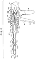
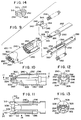
- the present invention is embodied in, and/or retrofittable to, an articulating endoscopic surgical stapling instrument, generally 50, including a distal stapling head assembly 60 which is pivotally connected to an elongated support shaft, or tube 70 rotatably or non-rotatably mounted on a proximal actuator handle assembly generally 80.
- a rotatable tube 70 When a rotatable tube 70 is used, a rotatable adjusting knob 82 may be mounted at the distal end of the actuator handle assembly 80 for rotating the support tube 70 about its longitudinal axis A1.
- a saddle-shaped actuator 84 is slidably mounted on the actuator handle assembly 80 for controlling the pivotal, or articulatable movement of the stapling head assembly 60 relative to the support tube 70 about an axis of articulation A2 running perpendicular to the support tube longitudinal axis A1.
- the actuator handle assembly 80 includes a depending handle grip 86 and a pivotally mounted staple actuating lever 88 for actuating a staple cartridge 100 on the stapling head assembly 60.
- the actuator handle assembly 80, the adjusting knob 82, the saddle-shaped actuator 84 and the staple actuating lever 88 consist of plastic material.
- the support tube 70 preferably includes a sleeve 600 which slidably and rotatably engages the shaft 70 such that the sleeve 600 may be slid toward or away from the stapling head assembly 60 and may be rotated about the shaft longitudinal axis A1 with respect to the stationery shaft 70.
- the stapling head assembly 60 may be articulated about a pivot or articulation axis A2, forming an angle of articulation with respect to the support tube axis A1.
- the stapling head assembly 60 has a longitudinal axis A3 that forms the angle of articulation with respect to the longitudinal axis A1 of the support tube 70, as illustrated.
- the stapling head assembly 60 may be rotated about its axis A3 as will subsequently be described. In the past, this rotation was not possible once the stapling head assembly 60 was placed inside the body.
- the present invention allows rotation of the staple cartridge 100 about the axis A3 at any angle of articulation inside the body. This rotational motion is possible by virtue of the first sleeve 600, which engages a second sleeve 602 fastened to the cartridge 100.
- the first sleeve 600 has a distal end 604 terminating proximate a pivot 236.
- the pivot 236 allows the staple cartridge 100 and stapling head assembly 60 to be articulated about the axis of articulation A2 relative to the support tube 70.
- the second external sleeve 602 has a proximal end 606 also terminating proximate the pivot 236.
- the distal and proximal ends 604 and 606 of the first and second sleeves 600 and 602, respectively, allow for the transfer of rotational motion from the first external sleeve 600 to the second external sleeve 602 to the stapling cartridge 100.
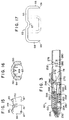
- the distal and proximal sleeve ends comprise a series of interconnecting teeth 608, preferably equally sized and shaped, separated by a plurality of notches, 609, also preferably equally sized and shaped, to complement the teeth 608.
- the teeth 608 of the distal end 604 are received by the notches 609, of the proximal end 606 and vise versa.
- the teeth 608 and notches 609 of each sleeve preferably mate with one another, with little or no gaps between them, as illustrated schematically in Figure 4a.
- rotation of the staple cartridge 100 can be varied, in terms of ease of rotation, by varying the number and depth of teeth 608 and complementary notches 609 on the first and second sleeves.
- the sleeves 600 and 602 each have 18 teeth 608 and notches 609.
- the second sleeve 602 is rotatably positioned around the non-rotating portion, e.g., the clamshell sleeve 224, and clamshell halves, 221, 222 ( Figure 6) of the stapling head assembly 60, and is fastened at its end 610 to the staple cartridge 100, which rotates, as will be subsequently described.
- the end 610 of the sleeve 602 may be fastened to the cartridge 100 in any number of ways, including the use of adhesives, pins, rivets, welding, etc.
- the distal end 604 of the first sleeve 600 may be withdrawn with respect to the second sleeve 602, is preferred that the second sleeve 602 be in a fixed position with respect to the cartridge 100 by being fastened thereto as previously described.
- the first sleeve 600 preferably includes a stop 601 at the end of the sleeve 600 proximate the handle assembly, generally 80, fastened to the support shaft 70.
- the stop 601 assists the surgeon in determining that the sleeve 600 has reached the handle 80 and has been stopped thereby, and may comprise an annular flange around the sleeve 600.
- the first sleeve 600 is biased either toward or away from the handle assembly 80, such as with a spring or other biasing means (not shown).
- the first sleeve distal end 604 and the second sleeve proximal end 606 comprise annular flanges 612 that engage each other with frictional surfaces 614.
- the frictional surfaces 614 may comprise an elastometeric material, such as natural or synthetic rubber, a stippled plastic or metallic surface, or a granulated surface, such as emery cloth or sandpaper, in addition to other frictional surfaces known to those skilled in the art of frictional surfaces.
- the annular flanges 612 may be arranged such that the outside diameter of the flange 612 on the first sleeve distal end 604 is smaller than the inside diameter of the flange 612 on the second sleeve proximal end 606.
- the teeth 608 or annular flanges 612 are replaced with bands of film, which may be adhesive film, connected by a series of strips.
- bands of film which may be adhesive film, connected by a series of strips.
- a first band of adhesive film 616 is fastened about the first sleeve 600 proximate the pivot 236, and a second band of adhesive film 618 is fastened about the second sleeve 602, also proximate the pivot 236.
- the bands 616 and 618 are joined by a plurality of film strips 620 positioned about the pivot 236 and transferring rotational forces from the first sleeve 600 to the second sleeve 602 to the staple cartridge 100.
- the film strips 620 are aligned substantially parallel to the longitudinal axis A1 of the support shaft 70.
- the bands 616, 617 and the films strips 620 preferably comprise a unitary piece of generally rectangular adhesive film, generally 615, having slits 622 forming the strips 620, as illustrated.
- the unitary piece of film may be fabricated of any material suitable for the purpose, including, by way of example, but not limitation, nylon, polyethylene, Teflon®, Ultem®, and polypropylene.
- the film strips 520 may be coated on their internal surfaces with a friction reducing material, known to those skilled in the art, for reducing friction of the strips 520 with respect to the pivot 236.
- Such materials include, by way of example, but not limitation, Teflon®, silicone, and polyethylene.
- a staple 65 adapted for use with the surgical stapling instrument 50 of the present invention comprises a wire-like body of circular cross section which is bent in a generally U-shaped configuration.
- the staple 65 consists of titanium or stainless steel.
- the staple 65 includes a top portion or crown 66 provided with a central dimpled portion 67 which is offset downwardly from the crown 66 by an amount approximately equal to the diameter of the circular cross section of the staple 65.
- the opposite sides of the staple 65 are bent downwardly to provide a pair of depending legs 68 which are substantially perpendicular to the crown 66.
- Each leg 68 has a beveled end 69 which is beveled at an angle of approximately 45 degrees.
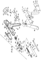
- the handle assembly 80 includes a pair of hollow handle sections 91 and 92 which are adapted to snap fit together.
- the handle sections 91 and 92 include distally extending elongated, semi-cylindrical neck portions 93 and 94 which receive the proximal end of the support tube 70 therebetween and mount the support tube 70 for rotation about its longitudinal axis relative to the handle assembly 80.
- the support tube 70 may be fixed, rather than rotatable, with respect to the handle assembly 80, in which case the surgeon rotates the entire handle assemble 80 to rotate the support tube 70 inside the cannula and/or the body cavity.
- Each of the handle sections 91 and 92 includes an internal annular flange 95 (one shown) for engaging a radially projecting flange 72 at the proximal end of the support tube 70 to retain the support tube 70 within the handle assembly 80.
- the staple actuating lever 88 is pivotally mounted on the actuator handle assembly 80 by a pivot pin 96 extending through a pivot hole 90 in the lever 88.
- the pivot pin 96 is received in a pair of hollow cylindrical support stems 97 (one shown) formed on the inside of the handle sections 91 and 92.
- the adjusting knob 82 comprises a pair of elongated hollow, tapered sleeve-like sections 101 and 102 which fit together over the neck portions 93 and 94 of the handle sections 91 and 92, respectively.
- Each of the sleeve-like knob sections 101 and 102 has an inwardly projecting prong 103 adjacent to its distal end.
- the prongs 103 are received in a pair of holes 74 (one shown) formed on opposite sides of the support tube 70 to secure the knob sections 101 and 102 to the support tube 70.
- Each of the knob sections 101 and 102 includes a semi-circular ratchet 104 on its inner wall for engaging a pair of detentes 105 mounted on resilient arms 106 formed on each of the handle sections 91 and 92.
- the semi-circular ratchets 104 and the detentes 105 provide a ratchet mechanism for retaining the support tube 70 in different rotational positions as the support tube 70 is rotated about its longitudinal axis.
- each ratchet 104 is provided with eight ratchet teeth which allow the support tube to be rotated in sixteen equal angular increments of 22-1/2 degrees.
- Each of the knob sections 101 and 102 has an enlarged rear section 107 provided with alternating longitudinal ridges 108 and finger-receiving grooves 109 which facilitate the rotation of the adjusting knob 82 and the support tube 70 by the surgeon.
- the support tube 70 is an elongated, thin-walled rigid metal tube, e.g., stainless steel. Inside the support tube 70 are mounted an elongated staple driver 76 and an elongated articulation driver 78 which are slidable longitudinally relative to the support tube 70 and relative to each other.
- the articulation driver 78 pivots the stapling head assembly 60 in response to movement of the saddle-shaped actuator 84 along the actuator handle assembly 80.
- the staple driver 76 actuates the staple forming mechanism within the staple cartridge 62 when the staple actuating lever 88 is operated.
- the staple driver 76 and the articulation driver 78 consist of stainless steel.
- the staple driver 76 comprises an elongated thin flat rod including a pair of spaced parallel flanges 110 which extend longitudinally along its top and bottom edges.
- the staple driver 76 has a pivot hole 111 ( Figure 6) adjacent to its distal end and a longitudinal slot 112 ( Figure 5) adjacent to its proximal end.
- the articulation driver 78 comprises an elongated thin flat rod which is slidably mounted adjacent to the staple driver 76 and is slidably received between the flanges 110.
- the articulation driver 78 has an enlarged distal portion 113 ( Figure 6) with a laterally projecting guide pin 114 formed adjacent to its distal end.
- An assembly hole 115 ( Figure 5) is formed adjacent to the proximal end of the articulation driver 78.
- a driver guide member 116 of generally cylindrical shape is mounted within the proximal end of the support tube 70.
- the driver guide member 116 has a pair of opposed, outwardly extending posts 117 which are received in a pair of corresponding holes 118 formed adjacent to the proximal end of the support tube 70.
- the driver guide 116 has a rectangular slot 119 extending therethrough for slidably receiving the staple driver 76 and the articulation driver 78.
- a driver coupling member 120 preferably made of plastic material, includes an opening 122 extending longitudinally therethrough for receiving the proximal ends of the staple driver 76 and the articulation driver 78.
- the driver coupling member 120 is secured to the articulation driver 78 by a coupling pin 124 which is received in the hole 115 in the articulation driver 78 and extends through a pair of apertures 126 formed on opposite sides of the coupling member 120.
- the coupling pin 124 is slidably received in the longitudinal slot 112 of the staple driver 76 to allow the articulation driver 78 to slide longitudinally relative to the staple driver 76.
- a pair of spaced annular flanges 128 and 130 are provided at the proximal end of the coupling member 120 for connection to an articulation control mechanism on the actuator handle assembly 80.
- the saddle-shaped actuator 84 operates a slide member 132 which is coupled to the driver coupling member 120 to operate the articulation driver 78.
- the saddle slide member 132 is a generally flat metal plate with an elongated neck 134 projecting distally and having a pair of curved depending arms 136 provided with inwardly projecting fingers 138 which are received between the annular flanges 128 and 130 on the driver coupling member 120.
- the annular flanges 128 and 130 capture the fingers 138 therebetween and connect the coupling member 120 to the saddle slide member 132 for longitudinal movement therewith.
- the annular flanges 138 allow the coupling member 120 to rotate about its longitudinal axis relative to the saddle slide member 132 when the support shaft 70 is rotated by the adjusting knob 82.
- the saddle slide member 132 is slidably mounted on a pair of horizontal support ledges 140 (one shown) formed on the interior of the handle sections 91 and 92. Each support ledge 140 includes a series of uniformly spaced notches 142 arranged in a longitudinal row.
- the saddle slide member 132 is formed with a transverse notch 144 for receiving a ratchet pin 146 which is biased downwardly into the notch 144 by a coil spring 148 mounted on an inclined post 149 formed on the inside of the saddle-shaped actuator 84.
- a pair of inclined fingers 150 ( Figures 15 and 16) is formed on the inside of the saddle-shaped actuator 84 and spaced from opposite sides of the post 149.
- the ratchet pin 146 extends transversely between the fingers 150 and is slidably received in an inclined slot 151 formed in each of the fingers 150.
- the opposite ends of the ratchet pin 146 are received in the notches 142 formed in the support ledges 140.
- the notches 142 and ratchet pin 146 provide a ratchet mechanism for controlling the angular orientation of the stapling head assembly 60 relative to the longitudinal axis of the support tube 70.
- the notches 142 provide a series of stop positions which correspond to angular orientations preferably of 0, 15, 30, 45 and 60 degrees relative to the longitudinal axis of the support tube 70.
- the saddle-shaped actuator 84 includes a pair of outwardly projecting ribs 85 which serve as finger grips to facilitate the longitudinal movement of the saddle-shaped actuator 84 along the handle assembly 60.
- the saddle-shaped actuator 84 includes a pair of inwardly projecting guides 87 ( Figures 15 and 16) formed on each of its opposite sides which are snap-fit and slidably received into a pair of longitudinally extending channels 89 (one shown) formed on the exterior of the handle sections 91 and 92.
- the staple actuating mechanism includes a driver link assembly 152 which is coupled to-the staple driver 76 and actuated by -the staple actuating lever 88.
- the driver link assembly 152 comprises a block-shaped slide member 154, preferably of plastic material, including a pair of vertically spaced flanges 156 extending from its opposite sides.
- Each of the handle sections 91 and 92 includes a horizontal support ledge 158 which is received between one pair of the side flanges 156 to slidably support the driver link assembly 152 on the actuator handle assembly 80.
- a cylindrical connector pin 160 projecting distally from the front of the slide block 154 includes an annular rim 162 for connecting the drive link assembly 152 to the staple driver 76.
- the connector pin 160 is inserted into a buckle-like connector 164 at the proximal end of the staple driver 76.
- the buckle-like connector 164 has a pair of longitudinally spaced bands 166 and 168 which are curved outwardly in opposite directions and capture the annular flange 162 therebetween to couple the staple driver 76 and the driver link assembly 152 together for movement along the longitudinal axis of the support tube 70. Also, the buckle-like connector 164 is free to rotate about the axis of the connector pin 160 to allow the staple driver 76 and the articulation driver 78 to rotate when the support tube 70 is rotated about its longitudinal axis.
- the staple actuating lever 88 includes a pair of upright fingers 170 which are spaced apart to receive a rearwardly projecting lug 172 formed on the slide member 154.
- the lug 172 is connected to a return coil spring 174 which is anchored to a post 176 on the handle section 92.
- the return spring 174 normally urges the slide 154 rearwardly into engagement with the upright arms 170 to retain the staple actuating lever 88 in the unactuated position ( Figure 2).
- the driver link assembly 152 includes a rearwardly projecting metal leaf spring 178 which is curved downwardly at its proximal end and provided with a pair of spring arms 180 projecting laterally from its opposite sides for engaging a pair of ratchets 182 (one shown) formed on the handle sections 91 and 92.
- the spring arms 180 and the ratchets 182 provide a ratchet mechanism which retains the driver link assembly 152 at different stages of advancement as the staple actuating lever 88 is actuated. Once the spring arms 180 are engaged with the ratchets 182, the driver link assembly 152 cannot return to its unactuated position until the stapling head assembly 60 is completely fired by operating the staple actuating lever 88.
- the stapling head assembly 60 is pivotally mounted at the distal end of the support tube 70 for pivotal movement about an axis transverse to the longitudinal axis of the support tube 70.
- the stapling head assembly 60 is pivotally mounted on the support tube 70 by a pivot connection, generally 200, including a pair of pivot housings 201 and 202 of generally semi-cylindrical shape which are fit together and are inserted into the digital end of the support tube 70.
- the pivot housings 201 and 202 are generally shaped as hollow semi-cylindrical sleeves for slidably receiving the staple driver 76 and the articulation driver 78.
- each of the pivot housings 201 and 202 Adjacent to the proximal end of each of the pivot housings 201 and 202 is a semi-circular groove 204 which receives an O-ring 206 for engaging the interior of the support tube 70.
- the O-ring 206 helps to vent the staple cartridge 100 at the insufflation pressures of-the-abdominal cavity.
- each of the pivot housings 201 and 202 includes a side opening 208 formed therein adjacent to the groove 204.
- silicone is injected into the side openings 208 about the staple driver 76 and the articulation driver 78.
- a pair of dimples 210 ( Figure 7) is formed on opposite sides of the support tube 70 to deform the tube material into the side openings 208 to fasten the pivot housings 201 and 202.
- a hollow cylindrical silicone plug 209 ( Figure 5) can be inserted into the proximal ends of the pivot housings 201 and 202.
- the silicone plug 209 includes a pair of distally projecting flanges 211 which slidably engage the outer surfaces of the staple driver 76 and the articulation driver 78.
- Each of the pivot housings 201 and 202 includes a distally projecting tang 212 which is provided with a pivot hole 214.
- the pivot housings 201 and 202 include front semi-circular flanges 216 which engage the distal end of the support tube 70.
- the pivot connection 200 includes a pair of clamshell members 221 and 222 which are generally semi-cylindrical in shape and fit together inside a tubular clamshell sleeve 224.
- the clamshell members 221 and 222 each include a front semi-circular flange 226 which engages the distal edge of the clamshell sleeve 224.
- the front flanges 226 each include an interior semi-circular groove 228.
- Each of the pivot housings 221 and 222 includes a detent arm 230 projecting inwardly through a side opening 232.
- each pivot housing 221 and 222 includes a rearwardly extending tang 234 provided with an outwardly projecting pivot pin 236.
- the pivot pins 236 on the clamshell members 221 and 222 are pivotally received in the pivot holes 214 on the pivot housings 201 and 202.
- the pivot housing 221 has an arc-shaped groove 238 formed on its interior surface for receiving the guide pin 114 on the articulation driver 78.
- the arc-shaped groove 238 and the guide pin 114 convert longitudinal movement of the articulation driver 78 into pivotal movement of the stapling head assembly 60.
- the pivot housings 201 and 202 and the clamshell members 221 and 222 consist of plastic material.
- the staple cartridge 100 of the stapling head assembly 60 has a hollow cylindrical housing 240 which is tapered at its distal end.
- the staple cartridge housing 240 is a one-piece molded plastic member.
- a hollow, generally cylindrical cartridge retainer 242 is inserted into the open proximal end of the staple cartridge housing 240.
- the cartridge retainer 242 has a pair of spring-like latch arms 244 located at diametrically opposed positions at the front of the retainer 242.
- the latch arms 244 are snap-fitted into a pair of diametrically opposed openings 245 adjacent to the proximal end of the cartridge housing 240 to hold the cartridge housing 240 and the retainer 242 together.
- the retainer 242 includes an annular flange 246 which is received in the annular grooves 228 of the clamshell members 221 and 222 to allow the staple cartridge 100 to rotate about its longitudinal axis relative to the support tube 70 and to the pivot connection 200.
- a set of twelve uniformly spaced circumferential teeth 248 is formed at the proximal end of the retainer 242.
- the teeth 248 are engaged by the detent arms 230 on the clamshell members 221 and 222.
- the detent arms 230 and teeth 248 provide a ratchet mechanism which allows the rotational orientation of the staple cartridge 100 to be adjusted in increments of 30 degrees.
- a staple forming mechanism comprising an anvil 250, a staple holder 252 and a staple former 254 which are preferably made of stainless steel.
- the staple former 254 is channel-shaped in configuration for slidably receiving the staple holder 252 therein.
- the staple former 254 has an elongated central slot 256 with a depending prong 258 at the proximal end of the slot 256.
- the staple holder 252 includes a depending prong 260 which is slidably received in the slot 256 and is biased away from the prong 258 by a compression coil spring 262.
- a feeder shoe 264 is slidably mounted within the staple cartridge 100 for urging a series of staples 65 toward the distal end of the cartridge 100.
- the feeder shoe 264 is biased in the distal direction by a compression coil spring 266 which is mounted on a distally projecting prong 268 on the cartridge retainer 242.
- the staple driver 76 is connected to the staple former 254 by a plunger 270 which is slidably mounted between the clamshell members 221 and 222.
- the plunger 270 is a generally flat metal plate, e.g. aluminum, and includes a longitudinally extending side flange 272 slidably received in a longitudinal groove 274 formed in the clamshell member 222.
- the plunger 270 has a pivot hole 276 adjacent to its proximal end.
- a pivot link 278 includes a pair of laterally projecting pivot pins 280 and 282 which are pivotally received in the pivot holes 111 and 276, respectively, to attach the staple driver 76 to the plunger 270.
- the pivot link 278 transfers the longitudinal movement of the staple driver 76 into longitudinal movement of the plunger 270. Also, the pivot link 278 permits the plunger 270 to pivot relative to the staple driver 76.
- a smaller diameter front disk 284 is spaced from a larger diameter rear disk 286.
- the front disk 284 is inserted between a pair of inwardly projecting fingers 288 at the proximal end of the staple former 254 to transfer the longitudinal movement of the plunger 270 into longitudinal movement of the staple former 254.
- the front disk 284 and the inwardly projecting fingers 288 permit the staple former 254 to rotate relative to the plunger 270.
- the staple cartridge housing 240 has an elongated hollow cylindrical wall 290 which preferably consists of transparent plastic material. Extending longitudinally inside the staple cartridge housing 240 is a first pair of elongated upstanding flanges 292 which are spaced apart and extend parallel to the longitudinal axis of the cylindrical wall 290.
- the elongated flanges 292 provide a set of guide rails for slidably supporting the staples 65 for longitudinal movement relative to the staple cartridge housing 240.
- Each flange or guide rail 292 has a ledge 293 ( Figure 10) which is inclined at an angle to the axis of the cartridge housing 240 and terminates in an extension 294 of the guide rail 292 at the open distal end of the cartridge housing 240.
- Each of the flanges 292 is spaced inwardly from the cylindrical wall 290 to provide a pair of elongated side channels 295 ( Figure 12) for receiving the depending legs 68 of the staples 65.
- the cartridge housing 240 includes a second pair of depending flanges 296 which are spaced apart and extend parallel to the longitudinal axis of the outer cylindrical wall 290.
- the upper flanges 296 terminate above the lower flanges 292 to provide a sufficient clearance therebetween to receive the crowns 66 of the staples 65.
- On the inside of each lower flange 292 is an elongated ledge 298 which slidably supports the staple former 254.
- the staple cartridge housing 240 has a tapered nose 300 at its distal end including an internal horizontal ledge 302 provided with a longitudinal channel 304 for receiving the anvil 250 of the stapling head assembly 100.
- the ledge 302 has a rearwardly projecting post 306 to which the anvil 250 is secured.
- the tapered nose 300 has a central depending tab 308 located above the ledge 302 and provided with a downwardly sloped rear edge 309 which serves as a guide for the dimpled portion 67 of the staple 65 advanced by the staple forming mechanism.
- the tapered nose 300 includes a pair of sloped ramps 310 (Figure 11) on opposite sides of the central tab 308 for engaging the crown 66 of the staple 65 which is advanced by the staple forming mechanism to pivot the staple 65 into an orientation parallel to the longitudinal axis of the cartridge housing 240.
- Each of the ramps 310 terminates at a ledge 312 located adjacent to one of the extensions 294 of the guide rails 292.
- a window 314 is formed on each side of the cartridge housing 240 adjacent to one of the ramps 310 as a result of the molding process used to form the cartridge housing 240.
- the staple former 254 is an elongated, channel-shaped member provided with upstanding side flangers 320 extending along its opposite sides.
- the staple holder 252 is an elongated plate-like member which is slidably supported on the staple former 254 and located between the side flanges 320.
- the compression coil spring 262 normally biases the staple holder 252 distally relative to the staple former 254 with the depending prong 260 biased against the distal end of the elongated central slot 256.
- the staple holder 252 and the staple 254 are inserted into the staple cartridge 240 between the lower upstanding flanges 292.
- the staple former 254 is slidably supported on the ledges 298 formed on the inside of the flanges 292.
- An ejector arm 322 extending from the distal end of the staple holder 252 has a notch 324 for receiving the dimpled portion 67 of the staple 65.
- a pusher finger 326 projects forwardly into the notch 324 at the distal end of the staple holder 252 for engaging the dimpled portion 67 of the staple 65 as the staple holder 252 is advanced to move the staple 65 into engagement with the anvil 250.
- the distal end of the ejector arm 322 is slanted away from the level of the pusher finger 326 and serves to disengage the staple 65 from the anvil 250 as the staple holder 252 is retracted after the staple 65 is formed.
- a pair of fingers 328 at the tip of the ejector arm 322 are spaced apart to receive the depending tab 308 of the cartridge housing 320 therebetween.
- the anvil 250 includes a pair of laterally spaced prongs 330 at its distal end which allow the ejector arm 322 to pass therebetween when the staple holder 252 is advanced.
- Each prong 330 includes an inclined ramp 332 for guiding the crown 66 of the staple 65 into engagement with the proximal side of the prong 330.
- the staple follower 264 is channel-shaped and includes a generally flat top portion 340 which is slidably received between the lower flanges 292 and the upper flanges 296.
- the staple follower 264 also has a pair of depending side flanges 342 on its opposite sides which are received in the channels 294 adjacent to the lower flanges 292.
- the staple follower 264 includes a rearwardly projecting post 344 which is inserted into the distal end of the compression coil spring 266.
- a stack of staples 65 is mounted in the staple cartridge housing 240 with the staple crowns 66 resting on and slidably supported by the elongated flanges or guide rails 292.
- the dimpled portions 67 of the staples 65 rest on top of the staple holder 252.
- the row of staples 65 is urged forwardly toward the distal end of the cartridge 240 by the staple follower 264 and the compression coil spring 266.
- the staple former 254 is biased rearwardly by the return spring 174 ( Figure 2) in the actuator handle assembly 80 to urge the depending prong 258 against the front of the retainer 242.
- the staple holder 252 is biased forwardly by the compression coil spring 262 which urges the depending prong 260 against the front edge of the slot 256 in the staple former 254.
- the ejector arm 322 at the distal end of the staple holder 252 is located adjacent to the guide tab 308 at the front of the tapered nose 300 of the staple cartridge 240.
- the offset or dimpled portion 67 of the forwardmost staple 65 is located at a level different from the remaining staples 65 in the stack.
- the dimpled portion 67 of the forwardmost staple 65 is received in the notch 324 in front of the pusher finger 326.
- the dimpled portion 67 of the forwardmost staple 65 is advanced along the sloped surface 309 and adjacent to the guide tab 308 by the pusher finger 326.
- the top portion or crown 66 of the forwardmost staple 65 is advanced along a path between the inclined ramps 310 ( Figure 14) and the inclined ledges 293 of the guide rails 292 to rotate the staple 65 by 90 degrees about its dimpled portion 67.
- the forwardmost staple 65 is rotated into a longitudinal orientation with its staple legs 68 parallel to the longitudinal axis of the staple cartridge housing 240. Thereafter, as shown in Figure 21, when the staple holder 252 is fully advanced, the forwardmost staple 65 travels along the extensions 294 of the guide rails 292 and is clamped against the anvil prongs 330 with the staple legs 68 projecting distally from the front of the staple cartridge housing 240. The remaining staples 65 in the stack are restrained by the top of the staple holder 252 which engages the dimpled portions 67 of the staples 65.
- the staple forming mechanism of the staple cartridge 100 is actuated by squeezing the staple actuating lever 88 toward the handle grip 86.
- the staple actuating lever 88 is pivoted about the pivot pin 96 and the upright fingers 170 advance the slide member 154 in the distal direction.
- the slide member 154 advances the staple driver 76 in the distal direction which, in turn, advances the plunger 270 to actuate the staple holder 252 and the staple former 254.
- the staple actuating lever 88 is released and returned to its original position by the return coil spring 174, which retracts the slide block 154 and the staple driver 76.
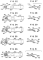
- Figures 22-26 show only one staple 65.
- Figure 22 shows the staple 65 positioned in the notch 324 in front of the pusher finger 326 at the start of the staple forming cycle which corresponds to the position of the staple holder 252 and staple former 254 shown in Figure 19.
- the staple actuating lever 88 is actuated, the staple holder 252 and the staple former 254 are advanced simultaneously to advance the staple 65 toward the prongs 330 of the anvil 250.
- the staple 65 is rotated by 90 degrees into a longitudinal orientation ( Figure 20) with the staple legs 68 pointing distally.
- Figure 23 shows the staple holder 252 and the staple former 254 advanced to a staple clamping position corresponding to Figure 21 in which the staple crown 66 is clamped between the pusher finger 326 and the prongs 330 of the anvil 250. Thereafter, as the staple actuating lever 88 is actuated, only the staple former 254 is advanced while the staple holder 252 remains stationary with the staple 65 clamped against the anvil prongs 330.
- Figure 24 shows the initial movement of the staple former 254 relative to the staple holder 252 to form the staple 65 about the anvil prongs 330.
- the initial contact of the former flanges 320 with the staple 65 results in a slight bending of the staple crown 66 with the staple legs 68 angled toward each other.
- Figure 25 shows an intermediate stage of the staple forming cycle in which the former flanges 320 are further advanced to bend the staple crown 66 around the anvil prongs 330 to bring the staple legs 68 closer together.
- Figure 26 shows the final stage of the staple forming cycle in which the former flanges 320 are fully advanced to bend the staple legs 68 into an overlapping configuration to secure the staple 65 to the tissue.
- the staple actuating lever 88 is released and the staple former 254 is moved rearwardly relative to the staple holder 252 by the compression coil spring 262.
- the staple holder 252 and the staple former 254 are retracted together by the return spring 174 in the actuator handle assembly 80.
- the ejector arm 322 lifts the formed staple 65 from the anvil prongs 330 as the staple holder 252 is retracted.
- the staple holder 252 and the staple former 254 are returned to the start position shown in Figure 19 where the next staple 65 is received in the notch 324 in front of the pusher finger 326. Then, the staple forming cycle is repeated to form the next staple 65.
- the actuator handle assembly 80 includes a precock ratchet mechanism comprising the ratchet spring 178 and the ratchets 182 which prevents the retraction of the staple forming mechanism until the staple 65 is completely formed.
- a precock ratchet mechanism comprising the ratchet spring 178 and the ratchets 182 which prevents the retraction of the staple forming mechanism until the staple 65 is completely formed.
- the operation of the ratchet mechanism is illustrated in Figures 27-31 which show the various ratchet positions corresponding to the stages of the staple forming cycle shown in Figures 22-26, respectively.
- each spring arm 180 of the ratchet spring 178 is initially disengaged from each ratchet 182 with the staple holder 252 and the staple former 254 located in the retracted position ( Figure 22).
- each spring arm 180 of the ratchet spring 178 is engaged in the first notch of each ratchet 182 with the staple holder 252 and the staple former 254 in the advanced position ( Figure 23) in which the staple 65 is clamped against the anvil prongs 330.
- the engagement of the ratchet spring arms 180 with the ratchets 182 prevents the staple holder 252 and the staple former 254 from being retracted until the staple forming cycle is completed.
- each spring arm 180 of the ratchet spring 178 is engaged in the second notch of each ratchet 182 with the flanges 320 of the staple former 254 initially engaged with the staple crown 66 to begin the forming of the staple 65 (Figure 24).
- each spring arm 180 of the ratchet spring 178 is engaged in the third notch of each ratchet 182 with the former flanges 320 advanced to the intermediate stage of the staple forming cycle ( Figure 25) in which the staple legs 68 are partially closed.
- each spring arm 180 of the ratchet spring 178 is disengaged from each ratchet 182 with the former flanges 320 fully advanced ( Figure 26) to bend the staple legs 68 into an overlapping relationship.
- Each spring arm 180 travels rearwardly adjacent to the unnotched side of the corresponding ratchet 182 to allow the ratchet spring 178 to return to its retracted position ( Figure 27) when the staple actuating lever 88 is released.
- the endoscopic surgical stapling instrument 50 is inserted into a body cavity through a trocar tube or cannula installed in a body wall.
- the surgical stapling instrument 50 is introduced into the body cavity in its non-articulated mode, i.e., with the staple cartridge 100 aligned with the longitudinal axis of the support tube 70.
- An endoscope may be inserted into the body cavity through a separate trocar tube or cannula for observation of the surgical site.
- the stapling cartridge 100 is positioned in the desired orientation over the surgical site by operating the rotatable adjusting knob 82 and the saddle-shaped actuator 84 to adjust the rotational orientation of the support tube 70 and the angular orientation of the staple cartridge 100.
- the staple cartridge 100 can be articulated to angles of 15, 30, 45 and 60 degrees relative to the support tube 70 by retracting the saddle-shaped actuator 84.
- the staple cartridge 100 is returned to the non-articulated mode by sliding the saddle-shaped actuator 84 forwardly.
- the surgical stapling instrument 50 is withdrawn from the trocar tube or cannula and the staple cartridge 100 is rotated manually relative to the support tube 70. Then, the surgical stapling instrument 50 is reintroduced into the body cavity in its non-articulated mode and the orientation of the staple cartridge 100 is adjusted by operating the rotatable adjusting knob 82 and the saddle-shaped actuator 84.
- the staple actuator lever 88 is squeezed to actuate the staple forming mechanism in the staple cartridge 100 to fasten one of the staples 65 to the tissue at the surgical site. Thereafter, the staple cartridge 100 is shifted to another location and the operation is repeated to fasten another staple 65 to the tissue. When the staple actuator lever 88 is released, the formed staple 65 is disengaged from the anvil 250 of the staple cartridge 100.
- the surgical stapling instrument 50 can be used to secure a hernia patch 62 at a desired surgical site.
- the hernia patch 62 is attached to internal body tissue 64 by applying a series of staples 65 to the edges of the hernia patch 62.
- the staple cartridge 100 is readily adjustable into the different orientations to apply the staples 65 at various locations along the edges of the hernia patch 62.
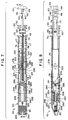
- Figures 32 and 33 illustrate an alternative embodiment of the surgical stapling instrument, generally 350, including a distal stapling head assembly 360 which is pivotally connected to an elongated support tube 370 rotatably mounted on a proximal actuator handle assembly 380.
- a rotatable adjusting knob 382 is mounted at the distal end of the actuator handle assembly 380 for rotating the support tube 370 about its longitudinal axis.
- a saddle-shaped actuator 384 is slidably mounted on the actuator handle assembly 380 for controlling the pivotal movement of the stapling head assembly 360 relative to the support tube 370.
- the actuator handle assembly 380 has a depending handle grip 386 and a pivotally mounted staple actuating lever 388 for actuating the stapling head assembly 360.
- the internal components of the stapling head assembly 360, the support shaft 370 and the actuator handle assembly 380 are substantially identical to the corresponding components of the surgical stapling instrument 50 described above. Accordingly, no detailed description of the internal components of the surgical stapling instrument 350 is necessary, and it will be understood by persons skilled in the art that the previous description of the internal components of the surgical stapling instrument 50 is applicable to the internal components of the surgical stapling instrument 350, unless otherwise described.
- the stapling head assembly 360 includes a rotatably mounted staple cartridge 400 which is substantially identical in construction to the stapling cartridge 100 described above.
- the stapling head assembly 360 is pivotally mounted on the support tube 370 by a pivot connection 390 which is substantially identical to the pivot connection 200 described above.
- the handle assembly 380 includes a pair of hollow handle sections 392 which are adapted to snap fit together.
- Each of the handle sections 392 includes a distally extending elongated, semi-cylindrical neck portion 394 in which the proximal end of the support tube 370 is received and mounted for rotation about its longitudinal axis relative to the handle assembly 380.
- Each of the handle sections 392 includes an internal annular flange 395 (one shown) for engaging a radially projecting flange 372 at the proximal end of the support tube 370 to retain the support tube 370 within the handle assembly 380.
- the staple actuating lever 388 is pivotally mounted on the actuator handle assembly 380 by a pivot pin 396.
- the adjusting knob 382 comprises a pair of elongated, hollow tapered sleeve-like sections 402 which fit together over the neck portions 394 of the handle sections 392.
- Each of the sleeve-like knob sections 402 has an inwardly projecting prong 403 adjacent to its distal end. The prongs 403 are received in a pair of holes formed on opposite sides of the support tube 370 to secure the knob sections 402 to the support tube 370.
- the actuator handle assembly 380 and the adjusting knob 382 include the same ratchet mechanism, described above in connection with the stapling instrument 50, which allows the adjusting knob 382 to rotate the support shaft 370 about its longitudinal axis in sixteen equal intervals of 22-1/2 degrees.
- Each of the knob sections 402 has an enlarged rear section 407 provided with alternating longitudinal ridges 408 and finger receiving grooves 409 which facilitate the rotation of the adjusting knob 382 and the support tube 370 by the surgeon.
- the actuator handle assembly 380 includes a rotatable control knob 410 for controlling the rotation of the staple cartridge 400 about its longitudinal axis relative to the support shaft 370.
- the control knob 410 includes an elongated hollow, conically tapered portion 412 which is rotatably received between the sleeve-like sections 402 of the adjusting knob 382 and the cylindrical neck portions 394 of the handle sections 392.
- a hollow cylindrical, internally toothed geneva gear wheel 414 is secured within the distal end of the conically tapered body 412 for rotation with the control knob 410.
- a first pinion gear 416 which is rotatably mounted on the inside of the support tube 370 extends through a window 372 (Figure 35) formed in the side of the support tube 370 and engages the internal teeth on the geneva gear wheel 414.
- the pinion gear 416 is attached to a flexible cable 418 which extends longitudinally through the support shaft 370 and the pivot connection 390.
- the distal end of the flexible cable 418 is connected to a second pinion gear 420 rotatably supported in a bushing 422 ( Figure 34) mounted on the inside of one of the clamshell members 424 forming part of the pivot connection 390.
- the flexible cable 418 is formed of conventional materials such as steel alloys.
- the staple cartridge 400 is mounted on a cylindrical retainer 426 which is rotatably supported by the clamshell members 424 of the pivot connection 390.
- the cartridge retainer 422 has an internally toothed geneva gear wheel 428 ( Figure 36) at its proximal end which engages the pinion gear 420.
- the control knob 410 is used to control the rotational orientation of the staple cartridge 400 relative to the support shaft 370 and the pivot connection 390.
- the rotation of the control knob 410 is transmitted via the flexible cable 418 to the cartridge retainer 422 which rotates the staple cartridge 400 about its axis.
- the rotational orientation of the staple cartridge 400 relative to the support shaft 370 is adjustable by the rotation of the control knob 410.
- the surgical stapling instrument 350 operates in substantially the same manner as the stapling instrument 50 described above.
- the rotatable adjusting knob 382 is used to rotate the support shaft 370 relative to the actuator handle assembly 380.
- the saddle-shaped actuator 384 is slidable longitudinally along the actuator handle assembly 380 to pivot the stapling head assembly 360 about an axis transverse to the longitudinal axis of the support shaft 370.
- the staple actuating lever 388 is pivoted to actuate the staple forming mechanism of the staple cartridge 400 in substantially the same manner as described above.
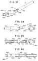
- FIGS 37-40 show an alternative embodiment of a stapling head assembly, generally 460, which can be used with the surgical stapling instrument 50 described above.
- the stapling head assembly 460 is pivotally mounted at the distal end of the support tube 70 by a pivot connection 470 including a tubular pivot housing 472 secured to the support tube 70 and a tubular cartridge support member 474 pivotally connected to the pivot housing 472 by a pair of pivot pins 476 extending laterally from opposite sides of the cartridge support member 474.
- An inclined slot 478 is formed on one side of the cartridge support member 474.
- a staple cartridge 600 is mounted at the distal end of the cartridge support member 474.
- the staple cartridge 600 is generally cylindrical in shape and is adapted to be received in the open distal end of the cartridge support member 474.
- the staple cartridge 600 has a pair of latch pins 602 projecting radially outward its opposite sides.
- the latch pins 602 are received and latched in a pair of slots 604 extending longitudinally from the distal end of the cartridge support member 474.
- the latch pins 602 and slots 604 allow the staple cartridge 600 to be disengaged from the cartridge support member 474 when it is desired to replace the staple cartridge 600.
- an articulation control member 480 is slidably mounted in the pivot housing 472 and is connected to the articulation driver 78.
- a laterally projecting guide pin 482 is located adjacent to the distal end of the articulation control member 480 and is slidably received in the inclined slot 478 of the cartridge support member 474.
- the inclined slot 478 and the guide pin 482 convert longitudinal movement of the articulation driver 78 into pivotal movement of the stapling head assembly 460 about the pivot pins 476.
- a plunger 490 is slidably mounted for longitudinal movement in the cartridge support member 474.
- the plunger 490 includes an elongated laterally projecting side flange 492 which is slidably received in a longitudinal slot 494 ( Figure 38) formed on the side of the cartridge support member 474.
- the plunger 490 has a semi-circular rear edge 495 which is engaged by an inclined cam surface 496 on a drive member 498 mounted at the distal end of the staple driver 76.
- the front end of the plunger 490 is engaged with the staple forming mechanism inside the staple cartridge 600.
- the plunger 490 is advanced to actuate the staple forming mechanism of the staple cartridge 600 which operates in substantially the same manner as described above.
- the semi-circular rear edge 496 of the plunger 90 and the inclined cam surface 498 at the distal end of the staple driver 76 allow the staple forming mechanism to be actuated in any angular orientation of the staple cartridge 600.
Abstract
Description
- This invention relates to surgical instruments having an articulating end pivotally connected to a shaft, wherein the articulating end may be rotated about a longitudinal axis over a plurality of angles of articulation with respect to the longitudinal axis of the shaft. More specifically, the present invention relates to endoscopic instruments such as a surgical stapling instrument for applying surgical staples to internal body tissue and, more particularly, to a surgical stapler which can be used endoscopically for the repair of hernias. Most specifically, this invention relates to an endoscopic surgical stapling instrument including a staple cartridge which is pivotally and rotatably mounted to allow the surgical staples to be applied to the internal body tissue in any desired orientation. Additionally, the present invention relates to an improved mechanism for providing articulation to the articulating end of the instrument.
- With the proliferation of endoscopic surgery, it has been realized that there are many procedures typically performed in open surgery which can be performed endoscopically. In endoscopic surgery, a trocar, which is a pointed piercing device, is inserted into the body with a cannula placed around the trocar. After the trocar pierces the body cavity walls, it is removed and the cannula remains in the body. Through this cannula, endoscopic procedures can be conducted. Generally, the endoscopic procedures are performed under insufflation. Some of the more typical endoscopic procedures have included gall bladder removal, tissue repair, and sterilization procedures such as occluding of fallopian tubes.
- Surgeons realize that it may be possible to perform additional procedures endoscopically, once the proper materials and mechanisms become available for performing these procedures. One of the more basic, and quite logical extensions of current endoscopic procedures has been focused on the repair of hernias. It is realized that to have the capability of performing hernia repair endoscopically will benefit the medical community in many ways. Specifically, it is realized that endoscopic hernia repair will allow the patient to recuperate more rapidly, and without the more than likely extensive physical therapy currently practiced as a result of a hernia repair performed by open surgery.
- Moreover, it is realized that hernia repair procedures may contain aspects which are applicable in other procedures. For instance, if it is possible to cover, or reinforce and constrain a hernia, it may be possible to apply this procedure to other vessels or organs, in a similar manner. Also, it is realized that once a device becomes available wherein hernias can be repaired, many of the functional components of the hernia repair device will be useful in other devices capable of performing other procedures. Also, naturally, these mechanisms may be useful for procedures in which open surgery is performed.
- In response to the above described needs, a number of surgical instruments have been developed for use in endoscopic stapling procedures. One such device, copending U.S. Patent Application Serial No. 759,014, filed September 12, 1991, (See EP-A-0536903) discloses a surgical stapler having a rigid, rotatable shaft containing a stack of staples aligned in a horizontal plane with respect to the shaft. This mechanism has proven quite effective in performing endoscopic surgical procedures; it does not, however, offer means for articulating the tip of the shaft containing the staples in response to a surgeon's need to alter the orientation of the device once it has been inserted into the patient.
- Copending U.S. Patent Application Serial No. 959,184 (See EP-A-0592244) discloses an endoscopic surgical device which includes an articulating tip allowing the surgeon to articulate a staple cartridge after the device has been inserted into the patient. The staple cartridge includes a stack of staples oriented in a vertical plane, which allows for a more efficient packing of staples in the device. EP-A-0592244 has been made available to the public after the priority date of the present application.
- In the device known from EP-A-0592244 no first and second external sleeve means engaging one another are provided as in the present invention in order to transfer rotational movement and rotate the staple cartridge after it has been articulated.
- Although the articulation device of the aforedescribed application is effective in providing articulation of the tip of the shaft, it is limited to providing a predetermined number of angles of articulation by use of a ratchet mechanism. Occasionally, the ratchet mechanism may bind and become difficult to operate smoothly.
- It would, therefore, be useful to provide an endoscopic surgical instrument that is capable of having an articulatable tip that could be rotated about its longitudinal axis in a plurality of angles of articulation with respect to the shaft. This rotation is provided by first and second engaging external sleeves. Additionally, a significant advance in the art would be realized if a new articulation device could be developed to better solve the aforementioned problems of ratchet-type articulation.
- Accordingly, it is an object of the present invention to provide an endoscopic surgical stapler for applying staples to secure a hernia repair patch to internal body tissue.
- Another object of the invention is to provide an endoscopic surgical stapler including a staple cartridge which is pivotally and rotatably mounted to allow the staples to be fastened to the tissue in any desired orientation.
- It is also an object of the invention to provide an endoscopic surgical stapling instrument in which the pivotal movement and rotation of the staple cartridge can be controlled from a remote actuator handle assembly.
- It is another object of the invention to provide an endoscopic surgical stapling instrument which facilitates manipulation by a surgeon to control the orientation and actuation of the staple cartridge.
- Yet another object of the invention is to provide an endoscopic surgical instrument having an articulatable tip, which tip may be rotated 360° about its axis after the tip has been articulated with respect to the longitudinal axis of the shaft to which it is pivotally connected.
- According to the present invention there is provided an endoscopic stapling mechanism as defined in the claims. The invention is adapted to provide rotational motion to a rotatable, articulatable staple cartridge of a surgical stapling instrument having a support shaft supporting the staple cartridge. The stapling instrument includes a pivot for pivoting the staple cartridge relative to the support shaft, and the staple cartridge has a longitudinal axis forming an angle of articulation relative to an axis passing longitudinally through the support shaft. The device of the invention allows the staple cartridge to be rotated about its longitudinal axis over a plurality of angles of articulation of the staple cartridge after the staple cartridge has been articulated with respect to the support shaft.
- The device includes a first external sleeve rotatably positioned on the support shaft and a second external sleeve positioned on and engaging the staple cartridge. The first external sleeve has a distal end terminating proximate the pivot and the second external sleeve has a proximal end terminating proximate the pivot. The distal and proximal sleeve ends of the first and second sleeves engage one another for transferring rotational motion from the first external sleeve to the second external sleeve and to the staple cartridge.
- In a preferred embodiment of the invention, the distal and proximal sleeve ends comprise interconnecting teeth positioned about the external sleeves. In another embodiment of the invention, the distal and proximal sleeve ends comprise frictional annular flanges. In yet another embodiment of the invention, the first and second sleeves are connected with a series of flexible film strips that are adhesively connected to the ends of the first and second sleeves.
- In yet another preferred embodiment of the invention, a stapling instrument is provided having an improved articulation device that includes a control knob rotatably mounted to the support shaft proximate the handle of the instrument. The device further includes a mechanism for transferring rotational motion of the control knob to an articulation driver in a longitudinal direction generally parallel to the longitudinal axis of the support shaft. The device further includes a flexible cable slidably positioned within the support shaft and connected at one end to the articulation driver and connected at its other end to the staple cartridge at a point spaced from the longitudinal axis of the staple cartridge.
- In yet another preferred embodiment of the invention, the control knob includes a worm gear for transferring rotational motion about the axis of the control knob to the articulation driver.
- In another preferred embodiment of the invention, the articulation driver includes a sleeve rotatably positioned on the support shaft, having an annular channel therein for slidably receiving a flange connected to the articulation driver. The channel is inclined with respect to the longitudinal axis of the support shaft, thereby providing longitudinal motion of the flange and articulation driver as the sleeve is rotated by the worm gear.
- The present invention further achieves an improved endoscopic surgical stapler which is adapted for insertion through an endoscopic tube or cannula into a body cavity to apply one or more surgical staples to the internal body tissue. The surgical stapling instrument includes a staple cartridge which is pivotally mounted at the distal end of a tubular support shaft extending from a handle which includes a staple actuator mechanism for actuating the staple cartridge to fasten the staples seriatim to the tissue. The staple cartridge is mounted for pivotal movement relative to the support shaft about an axis transverse to the longitudinal axis of the support shaft to permit the angular orientation of the staple cartridge to be adjusted. Also, the staple cartridge is mounted for rotation relative to the support shaft to permit the rotational orientation of the staple cartridge to be adjusted. In addition, the support shaft is rotatable about its longitudinal axis relative to the handle. These features of the stapling instrument allow the staple cartridge to be precisely aligned with the desired region of the internal body tissue to which the staple is applied. Separate actuator mechanisms are provided on the handle for controlling the rotation of the support shaft, the pivoting of the staple cartridge relative to the support shaft, and the rotation of the staple cartridge relative to the support shaft. These actuator mechanisms facilitate manipulation of the stapling instrument by a surgeon to position the staple cartridge in a desired orientation.
- In accordance with one aspect of the invention, the surgical stapling instrument is provided with pivot means at the distal end of the support shaft for mounting the staple cartridge for pivotal movement about an axis transverse to the longitudinal axis of the support shaft. Actuator means is provided on the handle for pivoting the staple cartridge about the transverse axis to adjust the angular position of the staple cartridge relative to the support shaft. The stapling instrument includes means for retaining the staple cartridge in different angular positions relative to the support shaft. The staple cartridge has a staple forming mechanism which can be actuated by the staple actuator mechanism with the staple cartridge oriented in any of its different angular positions.
- The surgical stapling instrument includes actuator means on the handle for rotating the support shaft about its longitudinal axis to adjust the rotational orientation of the support shaft and the staple cartridge. Also, means is provided for retaining the support shaft in different rotational positions as the support shaft is rotated about its longitudinal axis.
- In a preferred embodiment of the surgical stapling instrument, the staple cartridge is mounted for rotation about its longitudinal axis relative to the support shaft. Actuator means is provided on the handle for rotating the staple cartridge to adjust the rotational position of the staple cartridge relative to the support shaft. Also, means is provided for retaining the staple cartridge in different rotational positions as the staple cartridge is rotated about its longitudinal axis relative to the support shaft.
- In accordance with another aspect of the invention, a staple cartridge for use with-a stapling instrument for applying one or more surgical staples to tissue comprises a cartridge housing adapted to receive a plurality of staples in a row for longitudinal movement therethrough, an anvil mounted on the housing, means for advancing the forwardmost staple in the row into engagement with the anvil, means for rotating the forwardmost staple from a transverse orientation into a longitudinal orientation as the staple is advanced toward the anvil, and means for forming the forwardmost staple about the anvil to attach the staple to the tissue. The staple advancing means comprises a staple holder slidably mounted within the cartridge housing for advancing the forwardmost staple from the row and clamping the staple against the anvil. The staple rotating means comprises ramp means on the cartridge housing for engaging and rotating the forwardmost staple into a longitudinal orientation as the staple is advanced by the staple holder. The staple forming means comprises a staple former slidably mounted within the cartridge housing for movement relative to the staple holder and adapted to form the forwardmost staple about the anvil. Preferably, the staple holder includes an ejector arm for removing the forwardmost staple from the anvil after the staple is formed.
- A preferred embodiment of the staple cartridge is adapted for use with a staple having a generally U-shaped body including a crown with a central offset portion and a pair of depending legs at opposite sides of the crown. The staple cartridge comprises an elongated hollow cylindrical cartridge housing including a pair of spaced parallel guide rails therein for slidably supporting a stack of staples for longitudinal movement there along with the staple crowns resting on the guide rails and the staple legs oriented perpendicularly to the longitudinal axis of the cartridge housing. A staple follower is slidably mounted on the guide rails for urging the staples forwardly on the guide rails toward the distal end of the cartridge housing. An anvil is mounted adjacent to the distal end of the cartridge housing. A staple holder is slidably mounted between the guide rails for engaging the central offset portion of the forwardmost staple to advance the staple from the stack into engagement with the anvil. Ramp means is provided on the cartridge housing for engaging the crown of the forwardmost staple advanced by the staple holder and rotating the staple into a longitudinal orientation with the staple legs oriented parallel to the longitudinal axis of the cartridge housing. A staple former is slidably mounted between the guide rails and movable relative to the staple holder for engaging the crown of the forwardmost staple to form the staple about the anvil to attach the staple to the tissue.
- In the preferred embodiment of the staple cartridge, the staple former comprises an elongated channel-shaped member including upstanding side flanges extending along its opposite sides for engaging and forming the staple. The staple holder comprises an elongated plate-like member slidably supported on the staple former and located between the side flanges. The staple holder includes a notch at its distal end for receiving the forwardmost staple to be advanced. The staple holder also includes a pusher finger at its distal end for engaging the forwardmost staple and clamping the staple against the anvil. In addition, the staple holder includes an ejector arm at its distal end for removing the formed staple from the anvil when the staple holder is retracted.
- The foregoing and other objects, aspects and advantages will be better understood and more readily apparent to those of ordinary skill in the art, as the following detailed description of the preferred embodiments of the invention proceeds, particularly with reference to the accompanying illustrative figures, in which:
- Figure 1 is an overall perspective view of an endoscopic surgical stapling instrument constructed in accordance with a preferred embodiment of this invention;
- Figure 2 is a partially cutaway side view of the stapling instrument of Figure 1;
- Figure 3 is an enlarged longitudinal section of the stapling head and cartridge assembly of Figure 2;
- Figure 4 is an enlarged longitudinal section of the stapling head and cartridge assembly from the opposite side of Figure 3;
- Figure 4a is a schematic plan view of a portion of the first and second sleeves of a preferred embodiment of the invention, illustrating the interlocking teeth.
- Figures 5 and 6 are exploded perspective views showing the components of the stapling instrument of Figure 1;
- Figure 7 is an enlarged partially cutaway horizontal section of a portion of the stapling head assembly and support shaft of Figure 2;
- Figure 8 is an enlarged partially cutaway vertical section of a portion of the stapling head assembly and support shaft of Figure 2;
- Figure 9 is an enlarged, exploded perspective view showing the staple cartridge and the staple forming mechanism of the stapling head assembly;
- Figure 10 is an enlarged longitudinal section of the staple cartridge of Figure 9;
- Figure 11 is an enlarged longitudinal section of the staple cartridge along line 11-11 of Figure 10;
- Figure 12 is an enlarged proximal end view of the staple cartridge;
- Figure 13 is an enlarged distal end view of a portion of the stapling head assembly of Figure 3; Figure 14 is an enlarged fragmentary section of the staple cartridge taken along line 14-14 of Figure 11;
- Figure 15 is a longitudinal section of a slide actuator for pivoting the stapling head assembly;
- Figure 16 is a proximal end view of the slide actuator of Figure 15 Figure 17 is an enlarged plan view of a staple for use with the surgical stapling instrument of this invention;
- Figure 18 illustrates a hernia repair patch fastened to tissue with staples applied by the surgical stapling instrument of this invention;
- Figure 19 is an enlarged longitudinal section of the staple cartridge of Figure 9 showing the staple forming mechanism in a retracted position;
- Figure 20 is an enlarged longitudinal section of the staple cartridge of Figure 9 showing the staple forming mechanism advanced to rotate a staple into a longitudinal orientation;
- Figure 21 is an enlarged longitudinal section of the staple cartridge of Figure 9 showing the staple forming mechanism advanced to clamp the staple against an anvil of the staple cartridge;
- Figures 22-26 illustrate the operation of the staple forming mechanism in advancing and forming a staple;
- Figures 27-31 are fragmentary views showing the operation of a precock ratchet mechanism in the actuator handle assembly;
- Figure 32 is an overall perspective view of an alternative embodiment of the surgical stapling instrument constructed in accordance with this invention;
- Figure 33 is a partially cutaway side view of the stapling instrument of Figure 32;
- Figure 34 is an enlarged longitudinal section of the stapling head assembly from the opposite side of Figure 32;
- Figure 35 is an enlarged cross section of the stapling instrument along line 35-35 of Figure 33;
- Figure 36 is an enlarged cross section of the stapling instrument along line 36-36 of Figure 33;
- Figure 37 is a perspective view of another embodiment of a stapling head assembly for use with the surgical stapling instrument of this invention;
- Figure 38 is a side view of the stapling head assembly from the opposite side of Figure 37;
- Figure 39 is a partially cutaway side view of the stapling head assembly of Figure 38; and
- Figure 40 is a partially cutaway side view of the stapling head assembly from the opposite side of Figure 39.
- Figure 41 is an enlarged longitudinal section of the stapling head and cartridge assembly of the invention with frictional annular flanges for transferring rotational motion to the staple cartridge.
- Figure 42 is an enlarged longitudinal section of the stapling head and cartridge assembly of the invention with adhesive bands and film strips for transferring rotational motion to the staple cartridge.
- Figure 43 is a plan view of the adhesive bands and film strips of Figure 42 as formed from a unitary piece of material.
- Figures 5 to 40 show the stapling instrument of EP-A-0592244 and not the present invention. These figures are included for the understanding of the present invention.
- Referring to Figure 1, the present invention is embodied in, and/or retrofittable to, an articulating endoscopic surgical stapling instrument, generally 50, including a distal
stapling head assembly 60 which is pivotally connected to an elongated support shaft, ortube 70 rotatably or non-rotatably mounted on a proximal actuator handle assembly generally 80. When arotatable tube 70 is used, arotatable adjusting knob 82 may be mounted at the distal end of theactuator handle assembly 80 for rotating thesupport tube 70 about its longitudinal axis A1. - A saddle-shaped
actuator 84 is slidably mounted on theactuator handle assembly 80 for controlling the pivotal, or articulatable movement of the staplinghead assembly 60 relative to thesupport tube 70 about an axis of articulation A2 running perpendicular to the support tube longitudinal axis A1. Theactuator handle assembly 80 includes a dependinghandle grip 86 and a pivotally mountedstaple actuating lever 88 for actuating astaple cartridge 100 on the staplinghead assembly 60. Preferably, theactuator handle assembly 80, the adjustingknob 82, the saddle-shapedactuator 84 and thestaple actuating lever 88 consist of plastic material. - As illustrated in Figure 1, the
support tube 70 preferably includes asleeve 600 which slidably and rotatably engages theshaft 70 such that thesleeve 600 may be slid toward or away from the staplinghead assembly 60 and may be rotated about the shaft longitudinal axis A1 with respect to thestationery shaft 70. - As further illustrated in Figure 1, the stapling
head assembly 60 may be articulated about a pivot or articulation axis A2, forming an angle of articulation with respect to the support tube axis A1. The staplinghead assembly 60 has a longitudinal axis A3 that forms the angle of articulation with respect to the longitudinal axis A1 of thesupport tube 70, as illustrated. - The stapling
head assembly 60 may be rotated about its axis A3 as will subsequently be described. In the past, this rotation was not possible once the staplinghead assembly 60 was placed inside the body. The present invention, however, allows rotation of thestaple cartridge 100 about the axis A3 at any angle of articulation inside the body. This rotational motion is possible by virtue of thefirst sleeve 600, which engages asecond sleeve 602 fastened to thecartridge 100. As best seen in Figure 4, thefirst sleeve 600 has adistal end 604 terminating proximate apivot 236. Thepivot 236 allows thestaple cartridge 100 and staplinghead assembly 60 to be articulated about the axis of articulation A2 relative to thesupport tube 70. - The second
external sleeve 602 has aproximal end 606 also terminating proximate thepivot 236. The distal and proximal ends 604 and 606 of the first andsecond sleeves external sleeve 600 to the secondexternal sleeve 602 to thestapling cartridge 100. - In the embodiment of the invention illustrated in Figures 1 and 4, the distal and proximal sleeve ends comprise a series of interconnecting
teeth 608, preferably equally sized and shaped, separated by a plurality of notches, 609, also preferably equally sized and shaped, to complement theteeth 608. Theteeth 608 of thedistal end 604 are received by thenotches 609, of theproximal end 606 and vise versa. When thedistal end 604 of thefirst sleeve 600 is aligned with theproximal end 606 of thesecond sleeve 602, such that equals 0°, theteeth 608 andnotches 609 of each sleeve preferably mate with one another, with little or no gaps between them, as illustrated schematically in Figure 4a. - As will now be appreciated to those of ordinary skill in the art, rotation of the
staple cartridge 100 can be varied, in terms of ease of rotation, by varying the number and depth ofteeth 608 andcomplementary notches 609 on the first and second sleeves. In one preferred embodiment of the invention, thesleeves teeth 608 andnotches 609. - As further illustrated in Figure 4, the
second sleeve 602 is rotatably positioned around the non-rotating portion, e.g., theclamshell sleeve 224, and clamshell halves, 221, 222 (Figure 6) of the staplinghead assembly 60, and is fastened at itsend 610 to thestaple cartridge 100, which rotates, as will be subsequently described. Theend 610 of thesleeve 602 may be fastened to thecartridge 100 in any number of ways, including the use of adhesives, pins, rivets, welding, etc. Although thedistal end 604 of thefirst sleeve 600 may be withdrawn with respect to thesecond sleeve 602, is preferred that thesecond sleeve 602 be in a fixed position with respect to thecartridge 100 by being fastened thereto as previously described. - In the embodiment of the invention illustrated in Figure 1, the
first sleeve 600 preferably includes astop 601 at the end of thesleeve 600 proximate the handle assembly, generally 80, fastened to thesupport shaft 70. Thestop 601 assists the surgeon in determining that thesleeve 600 has reached thehandle 80 and has been stopped thereby, and may comprise an annular flange around thesleeve 600. - In another highly preferred embodiment of the invention, the
first sleeve 600 is biased either toward or away from thehandle assembly 80, such as with a spring or other biasing means (not shown). - In another preferred embodiment of the invention, illustrated in Figure 41, the first sleeve
distal end 604 and the second sleeveproximal end 606 compriseannular flanges 612 that engage each other withfrictional surfaces 614. In the embodiment of Figure 41, thefrictional surfaces 614 may comprise an elastometeric material, such as natural or synthetic rubber, a stippled plastic or metallic surface, or a granulated surface, such as emery cloth or sandpaper, in addition to other frictional surfaces known to those skilled in the art of frictional surfaces. Theannular flanges 612 may be arranged such that the outside diameter of theflange 612 on the first sleevedistal end 604 is smaller than the inside diameter of theflange 612 on the second sleeveproximal end 606. - In still another embodiment of the invention, the
teeth 608 orannular flanges 612 are replaced with bands of film, which may be adhesive film, connected by a series of strips. As illustrated in Figure 42, a first band ofadhesive film 616 is fastened about thefirst sleeve 600 proximate thepivot 236, and a second band ofadhesive film 618 is fastened about thesecond sleeve 602, also proximate thepivot 236. Thebands pivot 236 and transferring rotational forces from thefirst sleeve 600 to thesecond sleeve 602 to thestaple cartridge 100. As illustrated, the film strips 620 are aligned substantially parallel to the longitudinal axis A1 of thesupport shaft 70. - As best seen in Figure 43, the
bands 616, 617 and the films strips 620 preferably comprise a unitary piece of generally rectangular adhesive film, generally 615, havingslits 622 forming thestrips 620, as illustrated. In the embodiment of Figure 43, the unitary piece of film may be fabricated of any material suitable for the purpose, including, by way of example, but not limitation, nylon, polyethylene, Teflon®, Ultem®, and polypropylene. Additionally, the film strips 520 may be coated on their internal surfaces with a friction reducing material, known to those skilled in the art, for reducing friction of the strips 520 with respect to thepivot 236. Such materials include, by way of example, but not limitation, Teflon®, silicone, and polyethylene. - Referring to Figure 17, a staple 65 adapted for use with the
surgical stapling instrument 50 of the present invention comprises a wire-like body of circular cross section which is bent in a generally U-shaped configuration. Preferably, thestaple 65 consists of titanium or stainless steel. The staple 65 includes a top portion orcrown 66 provided with a centraldimpled portion 67 which is offset downwardly from thecrown 66 by an amount approximately equal to the diameter of the circular cross section of thestaple 65. The opposite sides of the staple 65 are bent downwardly to provide a pair of dependinglegs 68 which are substantially perpendicular to thecrown 66. Eachleg 68 has abeveled end 69 which is beveled at an angle of approximately 45 degrees. When the staple 65 is closed by operation of thesurgical stapling instrument 50, thestaple legs 68 overlap each other as shown by phantom lines in Figure 14 to secure the staple to the tissue. - As shown in Figures 1 and 5, the
handle assembly 80 includes a pair ofhollow handle sections handle sections semi-cylindrical neck portions support tube 70 therebetween and mount thesupport tube 70 for rotation about its longitudinal axis relative to thehandle assembly 80. Alternatively, thesupport tube 70 may be fixed, rather than rotatable, with respect to thehandle assembly 80, in which case the surgeon rotates the entire handle assemble 80 to rotate thesupport tube 70 inside the cannula and/or the body cavity. - Each of the
handle sections radially projecting flange 72 at the proximal end of thesupport tube 70 to retain thesupport tube 70 within thehandle assembly 80. Thestaple actuating lever 88 is pivotally mounted on theactuator handle assembly 80 by apivot pin 96 extending through apivot hole 90 in thelever 88. Thepivot pin 96 is received in a pair of hollow cylindrical support stems 97 (one shown) formed on the inside of thehandle sections - As shown in Figures 1 and 5, the adjusting
knob 82 comprises a pair of elongated hollow, tapered sleeve-like sections neck portions handle sections like knob sections prong 103 adjacent to its distal end. Theprongs 103 are received in a pair of holes 74 (one shown) formed on opposite sides of thesupport tube 70 to secure theknob sections support tube 70. Each of theknob sections semi-circular ratchet 104 on its inner wall for engaging a pair ofdetentes 105 mounted onresilient arms 106 formed on each of thehandle sections detentes 105 provide a ratchet mechanism for retaining thesupport tube 70 in different rotational positions as thesupport tube 70 is rotated about its longitudinal axis. For example, eachratchet 104 is provided with eight ratchet teeth which allow the support tube to be rotated in sixteen equal angular increments of 22-1/2 degrees. Each of theknob sections rear section 107 provided with alternatinglongitudinal ridges 108 and finger-receivinggrooves 109 which facilitate the rotation of the adjustingknob 82 and thesupport tube 70 by the surgeon. - The
support tube 70 is an elongated, thin-walled rigid metal tube, e.g., stainless steel. Inside thesupport tube 70 are mounted anelongated staple driver 76 and anelongated articulation driver 78 which are slidable longitudinally relative to thesupport tube 70 and relative to each other. Thearticulation driver 78 pivots the staplinghead assembly 60 in response to movement of the saddle-shapedactuator 84 along theactuator handle assembly 80. Thestaple driver 76 actuates the staple forming mechanism within thestaple cartridge 62 when thestaple actuating lever 88 is operated. Preferably, thestaple driver 76 and thearticulation driver 78 consist of stainless steel. - As shown in Figures 5 and 6, the
staple driver 76 comprises an elongated thin flat rod including a pair of spacedparallel flanges 110 which extend longitudinally along its top and bottom edges. Thestaple driver 76 has a pivot hole 111 (Figure 6) adjacent to its distal end and a longitudinal slot 112 (Figure 5) adjacent to its proximal end. Thearticulation driver 78 comprises an elongated thin flat rod which is slidably mounted adjacent to thestaple driver 76 and is slidably received between theflanges 110. Thearticulation driver 78 has an enlarged distal portion 113 (Figure 6) with a laterally projectingguide pin 114 formed adjacent to its distal end. An assembly hole 115 (Figure 5) is formed adjacent to the proximal end of thearticulation driver 78. Adriver guide member 116 of generally cylindrical shape is mounted within the proximal end of thesupport tube 70. Thedriver guide member 116 has a pair of opposed, outwardly extendingposts 117 which are received in a pair of correspondingholes 118 formed adjacent to the proximal end of thesupport tube 70. Thedriver guide 116 has arectangular slot 119 extending therethrough for slidably receiving thestaple driver 76 and thearticulation driver 78. - As shown in Figures 2 and 5, a
driver coupling member 120, preferably made of plastic material, includes anopening 122 extending longitudinally therethrough for receiving the proximal ends of thestaple driver 76 and thearticulation driver 78. Thedriver coupling member 120 is secured to thearticulation driver 78 by acoupling pin 124 which is received in thehole 115 in thearticulation driver 78 and extends through a pair ofapertures 126 formed on opposite sides of thecoupling member 120. Thecoupling pin 124 is slidably received in thelongitudinal slot 112 of thestaple driver 76 to allow thearticulation driver 78 to slide longitudinally relative to thestaple driver 76. A pair of spacedannular flanges coupling member 120 for connection to an articulation control mechanism on theactuator handle assembly 80. - The saddle-shaped
actuator 84 operates aslide member 132 which is coupled to thedriver coupling member 120 to operate thearticulation driver 78. Thesaddle slide member 132 is a generally flat metal plate with anelongated neck 134 projecting distally and having a pair of curved dependingarms 136 provided with inwardly projectingfingers 138 which are received between theannular flanges driver coupling member 120. Theannular flanges fingers 138 therebetween and connect thecoupling member 120 to thesaddle slide member 132 for longitudinal movement therewith. Theannular flanges 138 allow thecoupling member 120 to rotate about its longitudinal axis relative to thesaddle slide member 132 when thesupport shaft 70 is rotated by the adjustingknob 82. - The
saddle slide member 132 is slidably mounted on a pair of horizontal support ledges 140 (one shown) formed on the interior of thehandle sections support ledge 140 includes a series of uniformly spacednotches 142 arranged in a longitudinal row. Thesaddle slide member 132 is formed with atransverse notch 144 for receiving aratchet pin 146 which is biased downwardly into thenotch 144 by acoil spring 148 mounted on aninclined post 149 formed on the inside of the saddle-shapedactuator 84. A pair of inclined fingers 150 (Figures 15 and 16) is formed on the inside of the saddle-shapedactuator 84 and spaced from opposite sides of thepost 149. Theratchet pin 146 extends transversely between thefingers 150 and is slidably received in aninclined slot 151 formed in each of thefingers 150. - The opposite ends of the
ratchet pin 146 are received in thenotches 142 formed in thesupport ledges 140. Thenotches 142 and ratchetpin 146 provide a ratchet mechanism for controlling the angular orientation of the staplinghead assembly 60 relative to the longitudinal axis of thesupport tube 70. Thenotches 142 provide a series of stop positions which correspond to angular orientations preferably of 0, 15, 30, 45 and 60 degrees relative to the longitudinal axis of thesupport tube 70. - The saddle-shaped
actuator 84 includes a pair of outwardly projectingribs 85 which serve as finger grips to facilitate the longitudinal movement of the saddle-shapedactuator 84 along thehandle assembly 60. The saddle-shapedactuator 84 includes a pair of inwardly projecting guides 87 (Figures 15 and 16) formed on each of its opposite sides which are snap-fit and slidably received into a pair of longitudinally extending channels 89 (one shown) formed on the exterior of thehandle sections - Referring to Figures 2 and 5, the staple actuating mechanism includes a
driver link assembly 152 which is coupled to-thestaple driver 76 and actuated by -thestaple actuating lever 88. Thedriver link assembly 152 comprises a block-shapedslide member 154, preferably of plastic material, including a pair of vertically spacedflanges 156 extending from its opposite sides. Each of thehandle sections horizontal support ledge 158 which is received between one pair of theside flanges 156 to slidably support thedriver link assembly 152 on theactuator handle assembly 80. Acylindrical connector pin 160 projecting distally from the front of theslide block 154 includes anannular rim 162 for connecting thedrive link assembly 152 to thestaple driver 76. Theconnector pin 160 is inserted into a buckle-like connector 164 at the proximal end of thestaple driver 76. The buckle-like connector 164 has a pair of longitudinally spacedbands annular flange 162 therebetween to couple thestaple driver 76 and thedriver link assembly 152 together for movement along the longitudinal axis of thesupport tube 70. Also, the buckle-like connector 164 is free to rotate about the axis of theconnector pin 160 to allow thestaple driver 76 and thearticulation driver 78 to rotate when thesupport tube 70 is rotated about its longitudinal axis. - As shown in Figures 2 and 5, the
staple actuating lever 88 includes a pair ofupright fingers 170 which are spaced apart to receive a rearwardly projecting lug 172 formed on theslide member 154. The lug 172 is connected to areturn coil spring 174 which is anchored to apost 176 on thehandle section 92. Thereturn spring 174 normally urges theslide 154 rearwardly into engagement with theupright arms 170 to retain thestaple actuating lever 88 in the unactuated position (Figure 2). - The
driver link assembly 152 includes a rearwardly projectingmetal leaf spring 178 which is curved downwardly at its proximal end and provided with a pair ofspring arms 180 projecting laterally from its opposite sides for engaging a pair of ratchets 182 (one shown) formed on thehandle sections spring arms 180 and theratchets 182 provide a ratchet mechanism which retains thedriver link assembly 152 at different stages of advancement as thestaple actuating lever 88 is actuated. Once thespring arms 180 are engaged with theratchets 182, thedriver link assembly 152 cannot return to its unactuated position until the staplinghead assembly 60 is completely fired by operating thestaple actuating lever 88. - Referring to Figures 1 and 6, the stapling
head assembly 60 is pivotally mounted at the distal end of thesupport tube 70 for pivotal movement about an axis transverse to the longitudinal axis of thesupport tube 70. The staplinghead assembly 60 is pivotally mounted on thesupport tube 70 by a pivot connection, generally 200, including a pair ofpivot housings support tube 70. Thepivot housings staple driver 76 and thearticulation driver 78. Adjacent to the proximal end of each of thepivot housings semi-circular groove 204 which receives an O-ring 206 for engaging the interior of thesupport tube 70. The O-ring 206 helps to vent thestaple cartridge 100 at the insufflation pressures of-the-abdominal cavity. - As shown in Figure 5, each of the
pivot housings side opening 208 formed therein adjacent to thegroove 204. When thepivot housings side openings 208 about thestaple driver 76 and thearticulation driver 78. With thepivot housings support tube 70, a pair of dimples 210 (Figure 7) is formed on opposite sides of thesupport tube 70 to deform the tube material into theside openings 208 to fasten thepivot housings pivot housings silicone plug 209 includes a pair of distally projectingflanges 211 which slidably engage the outer surfaces of thestaple driver 76 and thearticulation driver 78. Each of thepivot housings distally projecting tang 212 which is provided with apivot hole 214. Thepivot housings semi-circular flanges 216 which engage the distal end of thesupport tube 70. - The
pivot connection 200 includes a pair ofclamshell members tubular clamshell sleeve 224. Theclamshell members semi-circular flange 226 which engages the distal edge of theclamshell sleeve 224. Thefront flanges 226 each include an interiorsemi-circular groove 228. Each of thepivot housings detent arm 230 projecting inwardly through aside opening 232. Also, eachpivot housing rearwardly extending tang 234 provided with an outwardly projectingpivot pin 236. The pivot pins 236 on theclamshell members pivot housings pivot housing 221 has an arc-shapedgroove 238 formed on its interior surface for receiving theguide pin 114 on thearticulation driver 78. The arc-shapedgroove 238 and theguide pin 114 convert longitudinal movement of thearticulation driver 78 into pivotal movement of the staplinghead assembly 60. Preferably, thepivot housings clamshell members - Referring to Figure 6, the
staple cartridge 100 of the staplinghead assembly 60 has a hollowcylindrical housing 240 which is tapered at its distal end. Preferably, thestaple cartridge housing 240 is a one-piece molded plastic member. A hollow, generallycylindrical cartridge retainer 242 is inserted into the open proximal end of thestaple cartridge housing 240. Thecartridge retainer 242 has a pair of spring-like latch arms 244 located at diametrically opposed positions at the front of theretainer 242. Thelatch arms 244 are snap-fitted into a pair of diametricallyopposed openings 245 adjacent to the proximal end of thecartridge housing 240 to hold thecartridge housing 240 and theretainer 242 together. Theretainer 242 includes anannular flange 246 which is received in theannular grooves 228 of theclamshell members staple cartridge 100 to rotate about its longitudinal axis relative to thesupport tube 70 and to thepivot connection 200. A set of twelve uniformly spacedcircumferential teeth 248 is formed at the proximal end of theretainer 242. Theteeth 248 are engaged by thedetent arms 230 on theclamshell members detent arms 230 andteeth 248 provide a ratchet mechanism which allows the rotational orientation of thestaple cartridge 100 to be adjusted in increments of 30 degrees. - Inside the
staple cartridge 100 is mounted a staple forming mechanism comprising ananvil 250, astaple holder 252 and a staple former 254 which are preferably made of stainless steel. The staple former 254 is channel-shaped in configuration for slidably receiving thestaple holder 252 therein. The staple former 254 has an elongatedcentral slot 256 with a dependingprong 258 at the proximal end of theslot 256. Thestaple holder 252 includes a dependingprong 260 which is slidably received in theslot 256 and is biased away from theprong 258 by acompression coil spring 262. Afeeder shoe 264 is slidably mounted within thestaple cartridge 100 for urging a series ofstaples 65 toward the distal end of thecartridge 100. Thefeeder shoe 264 is biased in the distal direction by acompression coil spring 266 which is mounted on adistally projecting prong 268 on thecartridge retainer 242. - The
staple driver 76 is connected to the staple former 254 by aplunger 270 which is slidably mounted between theclamshell members plunger 270 is a generally flat metal plate, e.g. aluminum, and includes a longitudinally extendingside flange 272 slidably received in alongitudinal groove 274 formed in theclamshell member 222. Theplunger 270 has apivot hole 276 adjacent to its proximal end. Apivot link 278 includes a pair of laterally projecting pivot pins 280 and 282 which are pivotally received in the pivot holes 111 and 276, respectively, to attach thestaple driver 76 to theplunger 270. The pivot link 278 transfers the longitudinal movement of thestaple driver 76 into longitudinal movement of theplunger 270. Also, the pivot link 278 permits theplunger 270 to pivot relative to thestaple driver 76. At the digital end of theplunger 270, a smallerdiameter front disk 284 is spaced from a larger diameterrear disk 286. Thefront disk 284 is inserted between a pair of inwardly projectingfingers 288 at the proximal end of the staple former 254 to transfer the longitudinal movement of theplunger 270 into longitudinal movement of the staple former 254. Thefront disk 284 and the inwardly projectingfingers 288 permit the staple former 254 to rotate relative to theplunger 270. - Referring to Figure 9, the
staple cartridge housing 240 has an elongated hollowcylindrical wall 290 which preferably consists of transparent plastic material. Extending longitudinally inside thestaple cartridge housing 240 is a first pair of elongatedupstanding flanges 292 which are spaced apart and extend parallel to the longitudinal axis of thecylindrical wall 290. Theelongated flanges 292 provide a set of guide rails for slidably supporting thestaples 65 for longitudinal movement relative to thestaple cartridge housing 240. Each flange orguide rail 292 has a ledge 293 (Figure 10) which is inclined at an angle to the axis of thecartridge housing 240 and terminates in anextension 294 of theguide rail 292 at the open distal end of thecartridge housing 240. Each of theflanges 292 is spaced inwardly from thecylindrical wall 290 to provide a pair of elongated side channels 295 (Figure 12) for receiving the dependinglegs 68 of thestaples 65. Thecartridge housing 240 includes a second pair of dependingflanges 296 which are spaced apart and extend parallel to the longitudinal axis of the outercylindrical wall 290. Theupper flanges 296 terminate above thelower flanges 292 to provide a sufficient clearance therebetween to receive thecrowns 66 of thestaples 65. On the inside of eachlower flange 292 is anelongated ledge 298 which slidably supports the staple former 254. - The
staple cartridge housing 240 has a taperednose 300 at its distal end including an internalhorizontal ledge 302 provided with alongitudinal channel 304 for receiving theanvil 250 of the staplinghead assembly 100. Theledge 302 has a rearwardly projectingpost 306 to which theanvil 250 is secured. Thetapered nose 300 has a central dependingtab 308 located above theledge 302 and provided with a downwardly slopedrear edge 309 which serves as a guide for thedimpled portion 67 of the staple 65 advanced by the staple forming mechanism. Also, thetapered nose 300 includes a pair of sloped ramps 310 (Figure 11) on opposite sides of thecentral tab 308 for engaging thecrown 66 of the staple 65 which is advanced by the staple forming mechanism to pivot the staple 65 into an orientation parallel to the longitudinal axis of thecartridge housing 240. Each of theramps 310 terminates at aledge 312 located adjacent to one of theextensions 294 of the guide rails 292. Awindow 314 is formed on each side of thecartridge housing 240 adjacent to one of theramps 310 as a result of the molding process used to form thecartridge housing 240. - As shown in Figure 9, the staple former 254 is an elongated, channel-shaped member provided with
upstanding side flangers 320 extending along its opposite sides. Thestaple holder 252 is an elongated plate-like member which is slidably supported on the staple former 254 and located between theside flanges 320. Thecompression coil spring 262 normally biases thestaple holder 252 distally relative to the staple former 254 with the dependingprong 260 biased against the distal end of the elongatedcentral slot 256. Thestaple holder 252 and the staple 254 are inserted into thestaple cartridge 240 between the lowerupstanding flanges 292. The staple former 254 is slidably supported on theledges 298 formed on the inside of theflanges 292. Anejector arm 322 extending from the distal end of thestaple holder 252 has anotch 324 for receiving thedimpled portion 67 of thestaple 65. Apusher finger 326 projects forwardly into thenotch 324 at the distal end of thestaple holder 252 for engaging thedimpled portion 67 of the staple 65 as thestaple holder 252 is advanced to move the staple 65 into engagement with theanvil 250. The distal end of theejector arm 322 is slanted away from the level of thepusher finger 326 and serves to disengage the staple 65 from theanvil 250 as thestaple holder 252 is retracted after the staple 65 is formed. A pair offingers 328 at the tip of theejector arm 322 are spaced apart to receive the dependingtab 308 of thecartridge housing 320 therebetween. - The
anvil 250 includes a pair of laterally spacedprongs 330 at its distal end which allow theejector arm 322 to pass therebetween when thestaple holder 252 is advanced. Eachprong 330 includes aninclined ramp 332 for guiding thecrown 66 of the staple 65 into engagement with the proximal side of theprong 330. - The
staple follower 264 is channel-shaped and includes a generally flattop portion 340 which is slidably received between thelower flanges 292 and theupper flanges 296. Thestaple follower 264 also has a pair of dependingside flanges 342 on its opposite sides which are received in thechannels 294 adjacent to thelower flanges 292. Thestaple follower 264 includes arearwardly projecting post 344 which is inserted into the distal end of thecompression coil spring 266. - Referring to Figures 9 and 19, a stack of
staples 65 is mounted in thestaple cartridge housing 240 with the staple crowns 66 resting on and slidably supported by the elongated flanges or guide rails 292. Thedimpled portions 67 of thestaples 65 rest on top of thestaple holder 252. The row ofstaples 65 is urged forwardly toward the distal end of thecartridge 240 by thestaple follower 264 and thecompression coil spring 266. The staple former 254 is biased rearwardly by the return spring 174 (Figure 2) in theactuator handle assembly 80 to urge the dependingprong 258 against the front of theretainer 242. Thestaple holder 252 is biased forwardly by thecompression coil spring 262 which urges the dependingprong 260 against the front edge of theslot 256 in the staple former 254. Theejector arm 322 at the distal end of thestaple holder 252 is located adjacent to theguide tab 308 at the front of thetapered nose 300 of thestaple cartridge 240. - As shown in Figure 19, the offset or
dimpled portion 67 of theforwardmost staple 65 is located at a level different from the remainingstaples 65 in the stack. Thedimpled portion 67 of theforwardmost staple 65 is received in thenotch 324 in front of thepusher finger 326. When thestaple holder 252 is advanced, thedimpled portion 67 of theforwardmost staple 65 is advanced along the slopedsurface 309 and adjacent to theguide tab 308 by thepusher finger 326. The top portion orcrown 66 of theforwardmost staple 65 is advanced along a path between the inclined ramps 310 (Figure 14) and theinclined ledges 293 of theguide rails 292 to rotate the staple 65 by 90 degrees about itsdimpled portion 67. - As shown in Figure 20, with the staple holder partially advanced, the
forwardmost staple 65 is rotated into a longitudinal orientation with itsstaple legs 68 parallel to the longitudinal axis of thestaple cartridge housing 240. Thereafter, as shown in Figure 21, when thestaple holder 252 is fully advanced, theforwardmost staple 65 travels along theextensions 294 of theguide rails 292 and is clamped against the anvil prongs 330 with thestaple legs 68 projecting distally from the front of thestaple cartridge housing 240. The remainingstaples 65 in the stack are restrained by the top of thestaple holder 252 which engages thedimpled portions 67 of thestaples 65. - The staple forming mechanism of the
staple cartridge 100 is actuated by squeezing thestaple actuating lever 88 toward thehandle grip 86. As a result, thestaple actuating lever 88 is pivoted about thepivot pin 96 and theupright fingers 170 advance theslide member 154 in the distal direction. Theslide member 154 advances thestaple driver 76 in the distal direction which, in turn, advances theplunger 270 to actuate thestaple holder 252 and the staple former 254. After thestaple holder 252 and the staple former 254 are fully advanced to form one of thestaples 65, thestaple actuating lever 88 is released and returned to its original position by thereturn coil spring 174, which retracts theslide block 154 and thestaple driver 76. - The operation of the staple forming mechanism is illustrated in Figures 22-26 which, for clarity, show only one
staple 65. Figure 22 shows the staple 65 positioned in thenotch 324 in front of thepusher finger 326 at the start of the staple forming cycle which corresponds to the position of thestaple holder 252 and staple former 254 shown in Figure 19. Initially, when thestaple actuating lever 88 is actuated, thestaple holder 252 and the staple former 254 are advanced simultaneously to advance the staple 65 toward theprongs 330 of theanvil 250. As thestaple 65 is advanced toward the anvil prongs 330, thestaple 65 is rotated by 90 degrees into a longitudinal orientation (Figure 20) with thestaple legs 68 pointing distally. - Figure 23 shows the
staple holder 252 and the staple former 254 advanced to a staple clamping position corresponding to Figure 21 in which thestaple crown 66 is clamped between thepusher finger 326 and theprongs 330 of theanvil 250. Thereafter, as thestaple actuating lever 88 is actuated, only the staple former 254 is advanced while thestaple holder 252 remains stationary with the staple 65 clamped against the anvil prongs 330. - Figure 24 shows the initial movement of the staple former 254 relative to the
staple holder 252 to form the staple 65 about the anvil prongs 330. The initial contact of theformer flanges 320 with the staple 65 results in a slight bending of thestaple crown 66 with thestaple legs 68 angled toward each other. - Figure 25 shows an intermediate stage of the staple forming cycle in which the
former flanges 320 are further advanced to bend thestaple crown 66 around the anvil prongs 330 to bring thestaple legs 68 closer together. Figure 26 shows the final stage of the staple forming cycle in which theformer flanges 320 are fully advanced to bend thestaple legs 68 into an overlapping configuration to secure the staple 65 to the tissue. - After the
staple 65 is completely formed, thestaple actuating lever 88 is released and the staple former 254 is moved rearwardly relative to thestaple holder 252 by thecompression coil spring 262. When the dependinglug 260 is engaged by the front edge of theslot 256, thestaple holder 252 and the staple former 254 are retracted together by thereturn spring 174 in theactuator handle assembly 80. Theejector arm 322 lifts the formedstaple 65 from the anvil prongs 330 as thestaple holder 252 is retracted. Thestaple holder 252 and the staple former 254 are returned to the start position shown in Figure 19 where thenext staple 65 is received in thenotch 324 in front of thepusher finger 326. Then, the staple forming cycle is repeated to form thenext staple 65. - The
actuator handle assembly 80 includes a precock ratchet mechanism comprising theratchet spring 178 and theratchets 182 which prevents the retraction of the staple forming mechanism until the staple 65 is completely formed. The operation of the ratchet mechanism is illustrated in Figures 27-31 which show the various ratchet positions corresponding to the stages of the staple forming cycle shown in Figures 22-26, respectively. - As shown in Figure 27, each
spring arm 180 of theratchet spring 178 is initially disengaged from eachratchet 182 with thestaple holder 252 and the staple former 254 located in the retracted position (Figure 22). As shown in Figure 28, eachspring arm 180 of theratchet spring 178 is engaged in the first notch of eachratchet 182 with thestaple holder 252 and the staple former 254 in the advanced position (Figure 23) in which thestaple 65 is clamped against the anvil prongs 330. Thereafter, the engagement of theratchet spring arms 180 with theratchets 182 prevents thestaple holder 252 and the staple former 254 from being retracted until the staple forming cycle is completed. - As shown in Figure 29, each
spring arm 180 of theratchet spring 178 is engaged in the second notch of eachratchet 182 with theflanges 320 of the staple former 254 initially engaged with thestaple crown 66 to begin the forming of the staple 65 (Figure 24). As shown in Figure 30, eachspring arm 180 of theratchet spring 178 is engaged in the third notch of eachratchet 182 with theformer flanges 320 advanced to the intermediate stage of the staple forming cycle (Figure 25) in which thestaple legs 68 are partially closed. - As shown in Figure 31, each
spring arm 180 of theratchet spring 178 is disengaged from eachratchet 182 with theformer flanges 320 fully advanced (Figure 26) to bend thestaple legs 68 into an overlapping relationship. Eachspring arm 180 travels rearwardly adjacent to the unnotched side of thecorresponding ratchet 182 to allow theratchet spring 178 to return to its retracted position (Figure 27) when thestaple actuating lever 88 is released. - In performing a hernia repair procedure, the endoscopic
surgical stapling instrument 50 is inserted into a body cavity through a trocar tube or cannula installed in a body wall. Initially, thesurgical stapling instrument 50 is introduced into the body cavity in its non-articulated mode, i.e., with thestaple cartridge 100 aligned with the longitudinal axis of thesupport tube 70. An endoscope may be inserted into the body cavity through a separate trocar tube or cannula for observation of the surgical site. The staplingcartridge 100 is positioned in the desired orientation over the surgical site by operating therotatable adjusting knob 82 and the saddle-shapedactuator 84 to adjust the rotational orientation of thesupport tube 70 and the angular orientation of thestaple cartridge 100. Thestaple cartridge 100 can be articulated to angles of 15, 30, 45 and 60 degrees relative to thesupport tube 70 by retracting the saddle-shapedactuator 84. - If it is desired to change the rotational orientation of the
staple cartridge 100 on its axis, thestaple cartridge 100 is returned to the non-articulated mode by sliding the saddle-shapedactuator 84 forwardly. Thesurgical stapling instrument 50 is withdrawn from the trocar tube or cannula and thestaple cartridge 100 is rotated manually relative to thesupport tube 70. Then, thesurgical stapling instrument 50 is reintroduced into the body cavity in its non-articulated mode and the orientation of thestaple cartridge 100 is adjusted by operating therotatable adjusting knob 82 and the saddle-shapedactuator 84. - With the
staple cartridge 100 adjusted to the desired orientation, thestaple actuator lever 88 is squeezed to actuate the staple forming mechanism in thestaple cartridge 100 to fasten one of thestaples 65 to the tissue at the surgical site. Thereafter, thestaple cartridge 100 is shifted to another location and the operation is repeated to fasten another staple 65 to the tissue. When thestaple actuator lever 88 is released, the formedstaple 65 is disengaged from theanvil 250 of thestaple cartridge 100. - Referring to Figure 18, the
surgical stapling instrument 50 can be used to secure ahernia patch 62 at a desired surgical site. Thehernia patch 62 is attached tointernal body tissue 64 by applying a series ofstaples 65 to the edges of thehernia patch 62. Thestaple cartridge 100 is readily adjustable into the different orientations to apply thestaples 65 at various locations along the edges of thehernia patch 62. - Figures 32 and 33 illustrate an alternative embodiment of the surgical stapling instrument, generally 350, including a distal
stapling head assembly 360 which is pivotally connected to anelongated support tube 370 rotatably mounted on a proximalactuator handle assembly 380. Arotatable adjusting knob 382 is mounted at the distal end of theactuator handle assembly 380 for rotating thesupport tube 370 about its longitudinal axis. A saddle-shapedactuator 384 is slidably mounted on theactuator handle assembly 380 for controlling the pivotal movement of the staplinghead assembly 360 relative to thesupport tube 370. Theactuator handle assembly 380 has a dependinghandle grip 386 and a pivotally mountedstaple actuating lever 388 for actuating the staplinghead assembly 360. The internal components of the staplinghead assembly 360, thesupport shaft 370 and theactuator handle assembly 380 are substantially identical to the corresponding components of thesurgical stapling instrument 50 described above. Accordingly, no detailed description of the internal components of thesurgical stapling instrument 350 is necessary, and it will be understood by persons skilled in the art that the previous description of the internal components of thesurgical stapling instrument 50 is applicable to the internal components of thesurgical stapling instrument 350, unless otherwise described. - The stapling
head assembly 360 includes a rotatably mountedstaple cartridge 400 which is substantially identical in construction to thestapling cartridge 100 described above. The staplinghead assembly 360 is pivotally mounted on thesupport tube 370 by apivot connection 390 which is substantially identical to thepivot connection 200 described above. - As shown in Figure 33, the
handle assembly 380 includes a pair ofhollow handle sections 392 which are adapted to snap fit together. Each of thehandle sections 392 includes a distally extending elongated,semi-cylindrical neck portion 394 in which the proximal end of thesupport tube 370 is received and mounted for rotation about its longitudinal axis relative to thehandle assembly 380. Each of thehandle sections 392 includes an internal annular flange 395 (one shown) for engaging aradially projecting flange 372 at the proximal end of thesupport tube 370 to retain thesupport tube 370 within thehandle assembly 380. Thestaple actuating lever 388 is pivotally mounted on theactuator handle assembly 380 by apivot pin 396. - As shown in Figures 32 and 33, the adjusting
knob 382 comprises a pair of elongated, hollow tapered sleeve-like sections 402 which fit together over theneck portions 394 of thehandle sections 392. Each of the sleeve-like knob sections 402 has an inwardly projectingprong 403 adjacent to its distal end. Theprongs 403 are received in a pair of holes formed on opposite sides of thesupport tube 370 to secure theknob sections 402 to thesupport tube 370. Theactuator handle assembly 380 and the adjustingknob 382 include the same ratchet mechanism, described above in connection with the staplinginstrument 50, which allows the adjustingknob 382 to rotate thesupport shaft 370 about its longitudinal axis in sixteen equal intervals of 22-1/2 degrees. Each of theknob sections 402 has an enlargedrear section 407 provided with alternatinglongitudinal ridges 408 andfinger receiving grooves 409 which facilitate the rotation of the adjustingknob 382 and thesupport tube 370 by the surgeon. - The
actuator handle assembly 380 includes arotatable control knob 410 for controlling the rotation of thestaple cartridge 400 about its longitudinal axis relative to thesupport shaft 370. Thecontrol knob 410 includes an elongated hollow, conically taperedportion 412 which is rotatably received between the sleeve-like sections 402 of the adjustingknob 382 and thecylindrical neck portions 394 of thehandle sections 392. A hollow cylindrical, internally toothedgeneva gear wheel 414 is secured within the distal end of the conicallytapered body 412 for rotation with thecontrol knob 410. Afirst pinion gear 416 which is rotatably mounted on the inside of thesupport tube 370 extends through a window 372 (Figure 35) formed in the side of thesupport tube 370 and engages the internal teeth on thegeneva gear wheel 414. Thepinion gear 416 is attached to aflexible cable 418 which extends longitudinally through thesupport shaft 370 and thepivot connection 390. The distal end of theflexible cable 418 is connected to asecond pinion gear 420 rotatably supported in a bushing 422 (Figure 34) mounted on the inside of one of theclamshell members 424 forming part of thepivot connection 390. Theflexible cable 418 is formed of conventional materials such as steel alloys. Thestaple cartridge 400 is mounted on acylindrical retainer 426 which is rotatably supported by theclamshell members 424 of thepivot connection 390. Thecartridge retainer 422 has an internally toothed geneva gear wheel 428 (Figure 36) at its proximal end which engages thepinion gear 420. - In the operation of the
surgical stapling instrument 350, thecontrol knob 410 is used to control the rotational orientation of thestaple cartridge 400 relative to thesupport shaft 370 and thepivot connection 390. The rotation of thecontrol knob 410 is transmitted via theflexible cable 418 to thecartridge retainer 422 which rotates thestaple cartridge 400 about its axis. As a result, the rotational orientation of thestaple cartridge 400 relative to thesupport shaft 370 is adjustable by the rotation of thecontrol knob 410. - Except for the
control knob 410 which rotates thestaple cartridge 400, thesurgical stapling instrument 350 operates in substantially the same manner as the staplinginstrument 50 described above. Therotatable adjusting knob 382 is used to rotate thesupport shaft 370 relative to theactuator handle assembly 380. The saddle-shapedactuator 384 is slidable longitudinally along theactuator handle assembly 380 to pivot the staplinghead assembly 360 about an axis transverse to the longitudinal axis of thesupport shaft 370. Thestaple actuating lever 388 is pivoted to actuate the staple forming mechanism of thestaple cartridge 400 in substantially the same manner as described above. - Figures 37-40 show an alternative embodiment of a stapling head assembly, generally 460, which can be used with the
surgical stapling instrument 50 described above. The staplinghead assembly 460 is pivotally mounted at the distal end of thesupport tube 70 by apivot connection 470 including atubular pivot housing 472 secured to thesupport tube 70 and a tubularcartridge support member 474 pivotally connected to thepivot housing 472 by a pair of pivot pins 476 extending laterally from opposite sides of thecartridge support member 474. Aninclined slot 478 is formed on one side of thecartridge support member 474. - A
staple cartridge 600 is mounted at the distal end of thecartridge support member 474. Thestaple cartridge 600 is generally cylindrical in shape and is adapted to be received in the open distal end of thecartridge support member 474. Thestaple cartridge 600 has a pair of latch pins 602 projecting radially outward its opposite sides. The latch pins 602 are received and latched in a pair ofslots 604 extending longitudinally from the distal end of thecartridge support member 474. The latch pins 602 andslots 604 allow thestaple cartridge 600 to be disengaged from thecartridge support member 474 when it is desired to replace thestaple cartridge 600. - As shown Figure 40, an
articulation control member 480 is slidably mounted in thepivot housing 472 and is connected to thearticulation driver 78. A laterally projectingguide pin 482 is located adjacent to the distal end of thearticulation control member 480 and is slidably received in theinclined slot 478 of thecartridge support member 474. Theinclined slot 478 and theguide pin 482 convert longitudinal movement of thearticulation driver 78 into pivotal movement of the staplinghead assembly 460 about the pivot pins 476. - As shown in Figure 39, a
plunger 490 is slidably mounted for longitudinal movement in thecartridge support member 474. Theplunger 490 includes an elongated laterally projectingside flange 492 which is slidably received in a longitudinal slot 494 (Figure 38) formed on the side of thecartridge support member 474. Theplunger 490 has a semi-circularrear edge 495 which is engaged by aninclined cam surface 496 on adrive member 498 mounted at the distal end of thestaple driver 76. The front end of theplunger 490 is engaged with the staple forming mechanism inside thestaple cartridge 600. - When the
staple driver 76 is advanced in the distal direction, theplunger 490 is advanced to actuate the staple forming mechanism of thestaple cartridge 600 which operates in substantially the same manner as described above. The semi-circularrear edge 496 of theplunger 90 and theinclined cam surface 498 at the distal end of thestaple driver 76 allow the staple forming mechanism to be actuated in any angular orientation of thestaple cartridge 600.
Claims (5)
- An endoscopic surgical stapling instrument (50) for applying one or more surgical staples to tissue, comprising:a handle (80) including a staple actuator mechanism (88);a tubular support shaft (70) having a longitudinal axis and extending from said handle (80);a staple cartridge (100) mounted on said support shaft (70) and connected to said staple actuator mechanism (88) for applying one or more staples to the tissue;said staple cartridge (100) being mounted for rotation about its longitudinal axis (A3) and relative to said support shaft (70) to permit the rotational orientation of said staple cartridge (100) to be adjusted;pivot means (236) for articulating said staple cartridge (100) relative to said support shaft (70);means for retaining said staple cartridge (100) in different rotational orientations as said staple cartridge (100) is rotated;means for retaining said staple cartridge (100) in different articulated orientations as said staple cartridge (100) is articulated;first control means (82) proximate said handle (86) for rotating said staple cartridge (100) relative to said support shaft (70);second control means (84) proximate said handle (86) for articulating said staple cartridge (100) relative to said support shaft (70);first external sleeve means (600) rotatably positioned on said tubular support shaft (70); andsecond external sleeve means (602) engaging said staple cartridge (100), said first external sleeve means (600) having a distal end (604) terminating proximate said pivot means (236), said second external sleeve means (602) having a proximal end (606) terminating proximate said pivot means (236), said distal and proximal sleeve ends (604, 606) engaging one another for transferring rotational movement from said first external sleeve (600) to said second external sleeve (602) and to said staple cartridge (100), wherein first and second sleeve means (600, 602) allow rotation of the staple cartridge (100) after the staple cartridge (100) has been articulated.
- The endoscopic stapling instrument (50) of claim 1, wherein said distal and proximal sleeve ends (604, 606) comprise interconnecting teeth (608) positioned about said first and second external sleeves (600, 602).
- The endoscopic stapling instrument (50) of claim 1, wherein said distal and proximal sleeve ends (604, 606) comprise frictional annular flanges (612).
- The endoscopic stapling instrument (50) of claim 1, wherein said distal end (604) of said first sleeve (600) includes a first band of adhesive film (616) fastened about said first sleeve (600) proximate said pivot means (236), wherein said proximal end (606) of said second sleeve (602) includes a second band (618) of adhesive film fastened about said second sleeve (602) proximate said pivot means (236), and said stapling instrument (50) further includes a plurality of film strips (620) joining said first band and second band (616, 618), said film strips (620) positioned about said pivot means (236) and transferring rotational forces from said first sleeve (600) to second said sleeve (602) to said staple cartridge (100).
- The endoscopic stapling instrument (50) of claim 1, which further includes:staple driver means for coupling said staple actuator mechanism (88) to a staple forming mechanism and actuating said staple forming mechanism in any angular position of said staple cartridge (100).
Applications Claiming Priority (2)
| Application Number | Priority Date | Filing Date | Title |
|---|---|---|---|
| US80462 | 1993-06-21 | ||
| US08/080,462 US5431323A (en) | 1992-10-09 | 1993-06-21 | Endoscopic surgical instrument with pivotable and rotatable staple cartridge |
Publications (2)
| Publication Number | Publication Date |
|---|---|
| EP0630614A1 EP0630614A1 (en) | 1994-12-28 |
| EP0630614B1 true EP0630614B1 (en) | 1997-08-20 |
Family
ID=22157537
Family Applications (1)
| Application Number | Title | Priority Date | Filing Date |
|---|---|---|---|
| EP94304460A Expired - Lifetime EP0630614B1 (en) | 1993-06-21 | 1994-06-20 | Endoscopic surgical instrument with pivotable and rotatable staple cartridge holding tip portion |
Country Status (9)
| Country | Link |
|---|---|
| US (3) | US5431323A (en) |
| EP (1) | EP0630614B1 (en) |
| JP (1) | JPH07136176A (en) |
| AT (1) | ATE156985T1 (en) |
| AU (1) | AU6486094A (en) |
| CA (1) | CA2126279A1 (en) |
| DE (1) | DE69405053T2 (en) |
| ES (1) | ES2105526T3 (en) |
| GR (1) | GR940100295A (en) |
Cited By (2)
| Publication number | Priority date | Publication date | Assignee | Title |
|---|---|---|---|---|
| EP3175801B1 (en) * | 2015-12-01 | 2021-12-29 | Karl Storz SE & Co. KG | Medical instrument |
| US11771421B2 (en) | 2019-07-10 | 2023-10-03 | Boston Scientific Scimed, Inc. | Systems, devices, and related methods for fastening tissue |
Families Citing this family (1016)
| Publication number | Priority date | Publication date | Assignee | Title |
|---|---|---|---|---|
| US6250532B1 (en) * | 1991-10-18 | 2001-06-26 | United States Surgical Corporation | Surgical stapling apparatus |
| US5514157A (en) * | 1992-02-12 | 1996-05-07 | United States Surgical Corporation | Articulating endoscopic surgical apparatus |
| US5662662A (en) | 1992-10-09 | 1997-09-02 | Ethicon Endo-Surgery, Inc. | Surgical instrument and method |
| US6716232B1 (en) * | 1993-04-30 | 2004-04-06 | United States Surgical Corporation | Surgical instrument having an articulated jaw structure and a detachable knife |
| US5797538A (en) * | 1994-10-05 | 1998-08-25 | United States Surgical Corporation | Articulating apparatus for applying surgical fasteners to body tissue |
| US5901895A (en) * | 1994-10-05 | 1999-05-11 | United States Surgical Corporation | Articulating apparatus for applying surgical fasteners to body tissue |
| US5868760A (en) * | 1994-12-07 | 1999-02-09 | Mcguckin, Jr.; James F. | Method and apparatus for endolumenally resectioning tissue |
| US5713505A (en) * | 1996-05-13 | 1998-02-03 | Ethicon Endo-Surgery, Inc. | Articulation transmission mechanism for surgical instruments |
| US5575799A (en) * | 1995-03-30 | 1996-11-19 | United States Surgical Corporation | Articulating surgical apparatus |
| US5782396A (en) | 1995-08-28 | 1998-07-21 | United States Surgical Corporation | Surgical stapler |
| US5762256A (en) | 1995-08-28 | 1998-06-09 | United States Surgical Corporation | Surgical stapler |
| US5797537A (en) * | 1996-02-20 | 1998-08-25 | Richard-Allan Medical Industries, Inc. | Articulated surgical instrument with improved firing mechanism |
| US6063098A (en) * | 1996-12-23 | 2000-05-16 | Houser; Kevin | Articulable ultrasonic surgical apparatus |
| US6051010A (en) * | 1996-12-23 | 2000-04-18 | Ethicon Endo-Surgery, Inc. | Methods and devices for joining transmission components |
| US5865361A (en) * | 1997-09-23 | 1999-02-02 | United States Surgical Corporation | Surgical stapling apparatus |
| US6171316B1 (en) | 1997-10-10 | 2001-01-09 | Origin Medsystems, Inc. | Endoscopic surgical instrument for rotational manipulation |
| US6332889B1 (en) * | 1998-08-27 | 2001-12-25 | Onux Medical, Inc. | Surgical suturing instrument and method of use |
| ATE363235T1 (en) * | 1999-09-09 | 2007-06-15 | Tuebingen Scient Medical Gmbh | SURGICAL INSTRUMENT FOR MINIMALLY INVASIVE PROCEDURES |
| US8016855B2 (en) * | 2002-01-08 | 2011-09-13 | Tyco Healthcare Group Lp | Surgical device |
| IL139788A (en) * | 2000-11-20 | 2006-10-05 | Minelu Zonnenschein | Stapler for endoscopes |
| EP1313401A4 (en) | 2000-08-30 | 2006-09-20 | Cerebral Vascular Applic Inc | Medical instrument |
| US7334717B2 (en) | 2001-10-05 | 2008-02-26 | Tyco Healthcare Group Lp | Surgical fastener applying apparatus |
| US7011668B2 (en) * | 2001-07-23 | 2006-03-14 | Dvl Acquistion Sub, Inc. | Surgical suturing instrument and method of use |
| US6719764B1 (en) | 2001-08-24 | 2004-04-13 | Scimed Life Systems, Inc. | Forward deploying suturing device and methods of use |
| US6755338B2 (en) | 2001-08-29 | 2004-06-29 | Cerebral Vascular Applications, Inc. | Medical instrument |
| WO2003024300A2 (en) * | 2001-09-14 | 2003-03-27 | Onux Medical, Inc. | Surgical suturing instrument and method of use |
| JP4245480B2 (en) * | 2001-10-05 | 2009-03-25 | タイコ ヘルスケア グループ エルピー | Surgical stapling apparatus and method |
| WO2003030743A2 (en) * | 2001-10-05 | 2003-04-17 | Tyco Healthcare Group Lp | Surgical stapling device |
| US7464847B2 (en) | 2005-06-03 | 2008-12-16 | Tyco Healthcare Group Lp | Surgical stapler with timer and feedback display |
| US10285694B2 (en) | 2001-10-20 | 2019-05-14 | Covidien Lp | Surgical stapler with timer and feedback display |
| US7331968B2 (en) * | 2004-06-14 | 2008-02-19 | Ethicon Endo-Surgery, Inc. | Endoscopic clip applier with threaded clip |
| EP1455656A1 (en) * | 2001-12-20 | 2004-09-15 | Rex Medical, L.P. | Apparatus and method for treating gastroesophageal reflux disease |
| US7238195B2 (en) | 2002-05-10 | 2007-07-03 | Tyco Healthcare Group Lp | Wound closure material applicator and stapler |
| JP2005525862A (en) * | 2002-05-17 | 2005-09-02 | オーナックス・メディカル・インコーポレーテッド | Surgical suture instrument and method of use thereof |
| US7217271B2 (en) * | 2002-09-13 | 2007-05-15 | Symmetry Medical, Inc. | Orthopaedic reamer driver for minimally invasive surgery |
| ES2348273T3 (en) | 2002-10-04 | 2010-12-02 | Tyco Healthcare Group Lp | SURGICAL STAPLING DEVICE. |
| DE60315846T2 (en) | 2002-10-04 | 2008-05-21 | Tyco Healthcare Group Lp, Norwalk | ASSEMBLY OF SURGICAL CLIP TOOL |
| JP4398865B2 (en) | 2002-10-04 | 2010-01-13 | タイコ ヘルスケア グループ エルピー | Surgical stapler with universal joint and tissue reserve |
| US20040073257A1 (en) * | 2002-10-09 | 2004-04-15 | Spitz Gregory A. | Methods and apparatus for the repair of hernias |
| US8627992B2 (en) * | 2002-12-16 | 2014-01-14 | Edrich Health Technologies, Inc. | Endovascular stapler |
| US7399310B2 (en) * | 2002-12-16 | 2008-07-15 | Edrich Vascular Devices, Inc. | Endovascular stapler |
| US7287682B1 (en) * | 2003-01-20 | 2007-10-30 | Hazem Ezzat | Surgical device and method |
| JP4331490B2 (en) * | 2003-02-27 | 2009-09-16 | オリンパス株式会社 | Surgical instrument |
| US20040243151A1 (en) | 2003-04-29 | 2004-12-02 | Demmy Todd L. | Surgical stapling device with dissecting tip |
| US9597078B2 (en) | 2003-04-29 | 2017-03-21 | Covidien Lp | Surgical stapling device with dissecting tip |
| EP1624811B1 (en) * | 2003-05-09 | 2007-02-21 | Tyco Healthcare Group Lp | Anastomotic staple with fluid dispensing capillary |
| US20070084897A1 (en) | 2003-05-20 | 2007-04-19 | Shelton Frederick E Iv | Articulating surgical stapling instrument incorporating a two-piece e-beam firing mechanism |
| US9060770B2 (en) | 2003-05-20 | 2015-06-23 | Ethicon Endo-Surgery, Inc. | Robotically-driven surgical instrument with E-beam driver |
| EP2314241B1 (en) | 2003-06-13 | 2013-08-07 | Covidien LP | Multiple member interconnect for surgical instrument and absorbable screw fastener |
| US7494039B2 (en) | 2003-06-17 | 2009-02-24 | Tyco Healthcare Group Lp | Surgical stapling device |
| WO2004112618A2 (en) | 2003-06-17 | 2004-12-29 | Tyco Healthcare Group, Lp | Surgical stapling device |
| US6981628B2 (en) * | 2003-07-09 | 2006-01-03 | Ethicon Endo-Surgery, Inc. | Surgical instrument with a lateral-moving articulation control |
| US7055731B2 (en) * | 2003-07-09 | 2006-06-06 | Ethicon Endo-Surgery Inc. | Surgical stapling instrument incorporating a tapered firing bar for increased flexibility around the articulation joint |
| US7111769B2 (en) * | 2003-07-09 | 2006-09-26 | Ethicon Endo-Surgery, Inc. | Surgical instrument incorporating an articulation mechanism having rotation about the longitudinal axis |
| US20050033317A1 (en) * | 2003-07-11 | 2005-02-10 | Ables Claudette M. | "Staple align", medical skin stapler with attached skin tissue forceps |
| US20050015113A1 (en) * | 2003-07-18 | 2005-01-20 | Baptiste Reginald C. | Guide system for controlled manipulation of surgical instruments |
| US6905057B2 (en) * | 2003-09-29 | 2005-06-14 | Ethicon Endo-Surgery, Inc. | Surgical stapling instrument incorporating a firing mechanism having a linked rack transmission |
| US10022123B2 (en) * | 2012-07-09 | 2018-07-17 | Covidien Lp | Surgical adapter assemblies for use between surgical handle assembly and surgical end effectors |
| US10041822B2 (en) | 2007-10-05 | 2018-08-07 | Covidien Lp | Methods to shorten calibration times for powered devices |
| US11311291B2 (en) | 2003-10-17 | 2022-04-26 | Covidien Lp | Surgical adapter assemblies for use between surgical handle assembly and surgical end effectors |
| US7296722B2 (en) | 2003-10-17 | 2007-11-20 | Tyco Healthcare Group Lp | Surgical fastener applying apparatus with controlled beam deflection |
| AU2004281832B2 (en) | 2003-10-17 | 2010-11-18 | Covidien Lp | Surgical stapling device with independent tip rotation |
| US7766207B2 (en) * | 2003-12-30 | 2010-08-03 | Ethicon Endo-Surgery, Inc. | Articulating curved cutter stapler |
| US20050177176A1 (en) * | 2004-02-05 | 2005-08-11 | Craig Gerbi | Single-fold system for tissue approximation and fixation |
| US20060000869A1 (en) * | 2004-05-17 | 2006-01-05 | Datascope Investment Corp. | Surgical stapling system |
| US8216255B2 (en) * | 2004-06-14 | 2012-07-10 | Ethicon Endo-Surgery, Inc. | Endoscopic clip applier actuator |
| US8215531B2 (en) | 2004-07-28 | 2012-07-10 | Ethicon Endo-Surgery, Inc. | Surgical stapling instrument having a medical substance dispenser |
| US8905977B2 (en) | 2004-07-28 | 2014-12-09 | Ethicon Endo-Surgery, Inc. | Surgical stapling instrument having an electroactive polymer actuated medical substance dispenser |
| US11890012B2 (en) | 2004-07-28 | 2024-02-06 | Cilag Gmbh International | Staple cartridge comprising cartridge body and attached support |
| US7553275B2 (en) | 2004-08-31 | 2009-06-30 | Surgical Solutions Llc | Medical device with articulating shaft |
| US7670284B2 (en) * | 2004-08-31 | 2010-03-02 | Surgical Solutions Llc | Medical device with articulating shaft |
| BRPI0419039B8 (en) * | 2004-09-10 | 2021-06-22 | Ethicon Endo Surgery Inc | surgical stapling instrument |
| US7887558B2 (en) * | 2004-09-28 | 2011-02-15 | Maquet Cardiovascular Llc | Modular vessel harvesting system and method |
| EP1719468A1 (en) * | 2004-12-17 | 2006-11-08 | Zimmer GmbH | Intervertebral stabilization system |
| US7784662B2 (en) * | 2005-02-18 | 2010-08-31 | Ethicon Endo-Surgery, Inc. | Surgical instrument with articulating shaft with single pivot closure and double pivot frame ground |
| US7654431B2 (en) * | 2005-02-18 | 2010-02-02 | Ethicon Endo-Surgery, Inc. | Surgical instrument with guided laterally moving articulation member |
| US7559450B2 (en) * | 2005-02-18 | 2009-07-14 | Ethicon Endo-Surgery, Inc. | Surgical instrument incorporating a fluid transfer controlled articulation mechanism |
| US7780054B2 (en) * | 2005-02-18 | 2010-08-24 | Ethicon Endo-Surgery, Inc. | Surgical instrument with laterally moved shaft actuator coupled to pivoting articulation joint |
| US20060289602A1 (en) * | 2005-06-23 | 2006-12-28 | Ethicon Endo-Surgery, Inc. | Surgical instrument with articulating shaft with double pivot closure and single pivot frame ground |
| US8021374B2 (en) * | 2005-03-08 | 2011-09-20 | The Trustees Of Stevens Institute Of Technology | Method and device for the controlled delivery and placement of securing elements in a body |
| US9138226B2 (en) | 2005-03-30 | 2015-09-22 | Covidien Lp | Cartridge assembly for a surgical stapling device |
| US7780055B2 (en) * | 2005-04-06 | 2010-08-24 | Tyco Healthcare Group Lp | Loading unit having drive assembly locking mechanism |
| US11291443B2 (en) | 2005-06-03 | 2022-04-05 | Covidien Lp | Surgical stapler with timer and feedback display |
| CA2609970C (en) * | 2005-06-03 | 2014-08-12 | Tyco Healthcare Group Lp | Battery powered surgical instrument |
| US20070027468A1 (en) * | 2005-08-01 | 2007-02-01 | Wales Kenneth S | Surgical instrument with an articulating shaft locking mechanism |
| US7419495B2 (en) * | 2005-08-25 | 2008-09-02 | Microline Pentax Inc. | Trigger lockout device for clip applying instrument |
| US8800838B2 (en) | 2005-08-31 | 2014-08-12 | Ethicon Endo-Surgery, Inc. | Robotically-controlled cable-based surgical end effectors |
| US20070194079A1 (en) * | 2005-08-31 | 2007-08-23 | Hueil Joseph C | Surgical stapling device with staple drivers of different height |
| US7669746B2 (en) | 2005-08-31 | 2010-03-02 | Ethicon Endo-Surgery, Inc. | Staple cartridges for forming staples having differing formed staple heights |
| US10159482B2 (en) | 2005-08-31 | 2018-12-25 | Ethicon Llc | Fastener cartridge assembly comprising a fixed anvil and different staple heights |
| US11246590B2 (en) | 2005-08-31 | 2022-02-15 | Cilag Gmbh International | Staple cartridge including staple drivers having different unfired heights |
| US7934630B2 (en) | 2005-08-31 | 2011-05-03 | Ethicon Endo-Surgery, Inc. | Staple cartridges for forming staples having differing formed staple heights |
| US9237891B2 (en) | 2005-08-31 | 2016-01-19 | Ethicon Endo-Surgery, Inc. | Robotically-controlled surgical stapling devices that produce formed staples having different lengths |
| US11484312B2 (en) | 2005-08-31 | 2022-11-01 | Cilag Gmbh International | Staple cartridge comprising a staple driver arrangement |
| US7467740B2 (en) * | 2005-09-21 | 2008-12-23 | Ethicon Endo-Surgery, Inc. | Surgical stapling instruments having flexible channel and anvil features for adjustable staple heights |
| CA2563147C (en) | 2005-10-14 | 2014-09-23 | Tyco Healthcare Group Lp | Surgical stapling device |
| US7673783B2 (en) * | 2005-11-04 | 2010-03-09 | Ethicon Endo-Surgery, Inc. | Surgical stapling instruments structured for delivery of medical agents |
| US20070106317A1 (en) | 2005-11-09 | 2007-05-10 | Shelton Frederick E Iv | Hydraulically and electrically actuated articulation joints for surgical instruments |
| US7673780B2 (en) | 2005-11-09 | 2010-03-09 | Ethicon Endo-Surgery, Inc. | Articulation joint with improved moment arm extension for articulating an end effector of a surgical instrument |
| US7799039B2 (en) | 2005-11-09 | 2010-09-21 | Ethicon Endo-Surgery, Inc. | Surgical instrument having a hydraulically actuated end effector |
| FR2895071B1 (en) * | 2005-12-19 | 2008-01-18 | Giat Ind Sa | ANTI-REBOUND LOCKING DEVICE OF A DEPLOYABLE FIN OF A PROJECTILE. |
| US8161977B2 (en) | 2006-01-31 | 2012-04-24 | Ethicon Endo-Surgery, Inc. | Accessing data stored in a memory of a surgical instrument |
| US8708213B2 (en) | 2006-01-31 | 2014-04-29 | Ethicon Endo-Surgery, Inc. | Surgical instrument having a feedback system |
| US20110006101A1 (en) | 2009-02-06 | 2011-01-13 | EthiconEndo-Surgery, Inc. | Motor driven surgical fastener device with cutting member lockout arrangements |
| US8763879B2 (en) | 2006-01-31 | 2014-07-01 | Ethicon Endo-Surgery, Inc. | Accessing data stored in a memory of surgical instrument |
| US7766210B2 (en) | 2006-01-31 | 2010-08-03 | Ethicon Endo-Surgery, Inc. | Motor-driven surgical cutting and fastening instrument with user feedback system |
| US7568603B2 (en) * | 2006-01-31 | 2009-08-04 | Ethicon Endo-Surgery, Inc. | Motor-driven surgical cutting and fastening instrument with articulatable end effector |
| US9861359B2 (en) | 2006-01-31 | 2018-01-09 | Ethicon Llc | Powered surgical instruments with firing system lockout arrangements |
| US8186555B2 (en) | 2006-01-31 | 2012-05-29 | Ethicon Endo-Surgery, Inc. | Motor-driven surgical cutting and fastening instrument with mechanical closure system |
| US20110024477A1 (en) | 2009-02-06 | 2011-02-03 | Hall Steven G | Driven Surgical Stapler Improvements |
| US20070175950A1 (en) * | 2006-01-31 | 2007-08-02 | Shelton Frederick E Iv | Disposable staple cartridge having an anvil with tissue locator for use with a surgical cutting and fastening instrument and modular end effector system therefor |
| US7753904B2 (en) | 2006-01-31 | 2010-07-13 | Ethicon Endo-Surgery, Inc. | Endoscopic surgical instrument with a handle that can articulate with respect to the shaft |
| US7770775B2 (en) | 2006-01-31 | 2010-08-10 | Ethicon Endo-Surgery, Inc. | Motor-driven surgical cutting and fastening instrument with adaptive user feedback |
| US11793518B2 (en) | 2006-01-31 | 2023-10-24 | Cilag Gmbh International | Powered surgical instruments with firing system lockout arrangements |
| US20120292367A1 (en) | 2006-01-31 | 2012-11-22 | Ethicon Endo-Surgery, Inc. | Robotically-controlled end effector |
| US7644848B2 (en) | 2006-01-31 | 2010-01-12 | Ethicon Endo-Surgery, Inc. | Electronic lockouts and surgical instrument including same |
| US20110290856A1 (en) | 2006-01-31 | 2011-12-01 | Ethicon Endo-Surgery, Inc. | Robotically-controlled surgical instrument with force-feedback capabilities |
| US8820603B2 (en) | 2006-01-31 | 2014-09-02 | Ethicon Endo-Surgery, Inc. | Accessing data stored in a memory of a surgical instrument |
| US11278279B2 (en) | 2006-01-31 | 2022-03-22 | Cilag Gmbh International | Surgical instrument assembly |
| US11224427B2 (en) | 2006-01-31 | 2022-01-18 | Cilag Gmbh International | Surgical stapling system including a console and retraction assembly |
| US7845537B2 (en) | 2006-01-31 | 2010-12-07 | Ethicon Endo-Surgery, Inc. | Surgical instrument having recording capabilities |
| US20070225562A1 (en) | 2006-03-23 | 2007-09-27 | Ethicon Endo-Surgery, Inc. | Articulating endoscopic accessory channel |
| US8721630B2 (en) | 2006-03-23 | 2014-05-13 | Ethicon Endo-Surgery, Inc. | Methods and devices for controlling articulation |
| US8992422B2 (en) | 2006-03-23 | 2015-03-31 | Ethicon Endo-Surgery, Inc. | Robotically-controlled endoscopic accessory channel |
| US8500631B2 (en) | 2006-03-27 | 2013-08-06 | Ethicon Endo-Surgery, Inc. | Methods and devices for percutaneous illumination |
| US7552854B2 (en) | 2006-05-19 | 2009-06-30 | Applied Medical Resources Corporation | Surgical stapler with firing lock mechanism |
| US8322455B2 (en) | 2006-06-27 | 2012-12-04 | Ethicon Endo-Surgery, Inc. | Manually driven surgical cutting and fastening instrument |
| US7740159B2 (en) | 2006-08-02 | 2010-06-22 | Ethicon Endo-Surgery, Inc. | Pneumatically powered surgical cutting and fastening instrument with a variable control of the actuating rate of firing with mechanical power assist |
| US7506791B2 (en) | 2006-09-29 | 2009-03-24 | Ethicon Endo-Surgery, Inc. | Surgical stapling instrument with mechanical mechanism for limiting maximum tissue compression |
| US10568652B2 (en) | 2006-09-29 | 2020-02-25 | Ethicon Llc | Surgical staples having attached drivers of different heights and stapling instruments for deploying the same |
| US10130359B2 (en) | 2006-09-29 | 2018-11-20 | Ethicon Llc | Method for forming a staple |
| US8708210B2 (en) | 2006-10-05 | 2014-04-29 | Covidien Lp | Method and force-limiting handle mechanism for a surgical instrument |
| US7845535B2 (en) | 2006-10-06 | 2010-12-07 | Tyco Healthcare Group Lp | Surgical instrument having a plastic surface |
| US7866525B2 (en) | 2006-10-06 | 2011-01-11 | Tyco Healthcare Group Lp | Surgical instrument having a plastic surface |
| US7699203B2 (en) * | 2006-11-13 | 2010-04-20 | Warsaw Orthopedic, Inc. | Variable angle surgical staple inserter |
| US8684253B2 (en) | 2007-01-10 | 2014-04-01 | Ethicon Endo-Surgery, Inc. | Surgical instrument with wireless communication between a control unit of a robotic system and remote sensor |
| US11291441B2 (en) | 2007-01-10 | 2022-04-05 | Cilag Gmbh International | Surgical instrument with wireless communication between control unit and remote sensor |
| US7721936B2 (en) | 2007-01-10 | 2010-05-25 | Ethicon Endo-Surgery, Inc. | Interlock and surgical instrument including same |
| US7721931B2 (en) | 2007-01-10 | 2010-05-25 | Ethicon Endo-Surgery, Inc. | Prevention of cartridge reuse in a surgical instrument |
| US8459520B2 (en) | 2007-01-10 | 2013-06-11 | Ethicon Endo-Surgery, Inc. | Surgical instrument with wireless communication between control unit and remote sensor |
| US7954682B2 (en) | 2007-01-10 | 2011-06-07 | Ethicon Endo-Surgery, Inc. | Surgical instrument with elements to communicate between control unit and end effector |
| US7738971B2 (en) | 2007-01-10 | 2010-06-15 | Ethicon Endo-Surgery, Inc. | Post-sterilization programming of surgical instruments |
| US8652120B2 (en) | 2007-01-10 | 2014-02-18 | Ethicon Endo-Surgery, Inc. | Surgical instrument with wireless communication between control unit and sensor transponders |
| US7900805B2 (en) | 2007-01-10 | 2011-03-08 | Ethicon Endo-Surgery, Inc. | Surgical instrument with enhanced battery performance |
| US11039836B2 (en) | 2007-01-11 | 2021-06-22 | Cilag Gmbh International | Staple cartridge for use with a surgical stapling instrument |
| US8540128B2 (en) | 2007-01-11 | 2013-09-24 | Ethicon Endo-Surgery, Inc. | Surgical stapling device with a curved end effector |
| US20090192530A1 (en) | 2008-01-29 | 2009-07-30 | Insightra Medical, Inc. | Fortified mesh for tissue repair |
| US7431188B1 (en) | 2007-03-15 | 2008-10-07 | Tyco Healthcare Group Lp | Surgical stapling apparatus with powered articulation |
| US8727197B2 (en) | 2007-03-15 | 2014-05-20 | Ethicon Endo-Surgery, Inc. | Staple cartridge cavity configuration with cooperative surgical staple |
| US8308725B2 (en) * | 2007-03-20 | 2012-11-13 | Minos Medical | Reverse sealing and dissection instrument |
| US8205780B2 (en) * | 2007-03-22 | 2012-06-26 | Tyco Healthcare Group Lp | Apparatus for forming variable height surgical fasteners |
| US8056787B2 (en) | 2007-03-28 | 2011-11-15 | Ethicon Endo-Surgery, Inc. | Surgical stapling and cutting instrument with travel-indicating retraction member |
| US8893946B2 (en) | 2007-03-28 | 2014-11-25 | Ethicon Endo-Surgery, Inc. | Laparoscopic tissue thickness and clamp load measuring devices |
| US7950560B2 (en) | 2007-04-13 | 2011-05-31 | Tyco Healthcare Group Lp | Powered surgical instrument |
| US11259801B2 (en) | 2007-04-13 | 2022-03-01 | Covidien Lp | Powered surgical instrument |
| US8800837B2 (en) | 2007-04-13 | 2014-08-12 | Covidien Lp | Powered surgical instrument |
| US20080255413A1 (en) | 2007-04-13 | 2008-10-16 | Michael Zemlok | Powered surgical instrument |
| US7823760B2 (en) | 2007-05-01 | 2010-11-02 | Tyco Healthcare Group Lp | Powered surgical stapling device platform |
| US7931660B2 (en) | 2007-05-10 | 2011-04-26 | Tyco Healthcare Group Lp | Powered tacker instrument |
| US9533122B2 (en) | 2007-05-18 | 2017-01-03 | Boston Scientific Scimed, Inc. | Catheter drive system with control handle rotatable about two axes separated from housing by shaft |
| US7798386B2 (en) | 2007-05-30 | 2010-09-21 | Ethicon Endo-Surgery, Inc. | Surgical instrument articulation joint cover |
| US7810693B2 (en) | 2007-05-30 | 2010-10-12 | Ethicon Endo-Surgery, Inc. | Surgical stapling and cutting instrument with articulatable end effector |
| US8157145B2 (en) | 2007-05-31 | 2012-04-17 | Ethicon Endo-Surgery, Inc. | Pneumatically powered surgical cutting and fastening instrument with electrical feedback |
| US20080300461A1 (en) * | 2007-05-31 | 2008-12-04 | Ethicon Endo-Surgery, Inc. | Endoscopic Device |
| US7905380B2 (en) | 2007-06-04 | 2011-03-15 | Ethicon Endo-Surgery, Inc. | Surgical instrument having a multiple rate directional switching mechanism |
| US7819299B2 (en) | 2007-06-04 | 2010-10-26 | Ethicon Endo-Surgery, Inc. | Surgical instrument having a common trigger for actuating an end effector closing system and a staple firing system |
| US11857181B2 (en) | 2007-06-04 | 2024-01-02 | Cilag Gmbh International | Robotically-controlled shaft based rotary drive systems for surgical instruments |
| US7832408B2 (en) | 2007-06-04 | 2010-11-16 | Ethicon Endo-Surgery, Inc. | Surgical instrument having a directional switching mechanism |
| US8931682B2 (en) | 2007-06-04 | 2015-01-13 | Ethicon Endo-Surgery, Inc. | Robotically-controlled shaft based rotary drive systems for surgical instruments |
| US8534528B2 (en) | 2007-06-04 | 2013-09-17 | Ethicon Endo-Surgery, Inc. | Surgical instrument having a multiple rate directional switching mechanism |
| US7510107B2 (en) | 2007-06-18 | 2009-03-31 | Ethicon Endo-Surgery, Inc. | Cable driven surgical stapling and cutting instrument with apparatus for preventing inadvertent cable disengagement |
| US7658311B2 (en) | 2007-06-22 | 2010-02-09 | Ethicon Endo-Surgery, Inc. | Surgical stapling instrument with a geared return mechanism |
| US7753245B2 (en) | 2007-06-22 | 2010-07-13 | Ethicon Endo-Surgery, Inc. | Surgical stapling instruments |
| US8308040B2 (en) | 2007-06-22 | 2012-11-13 | Ethicon Endo-Surgery, Inc. | Surgical stapling instrument with an articulatable end effector |
| US11849941B2 (en) | 2007-06-29 | 2023-12-26 | Cilag Gmbh International | Staple cartridge having staple cavities extending at a transverse angle relative to a longitudinal cartridge axis |
| US7624902B2 (en) | 2007-08-31 | 2009-12-01 | Tyco Healthcare Group Lp | Surgical stapling apparatus |
| US8061576B2 (en) | 2007-08-31 | 2011-11-22 | Tyco Healthcare Group Lp | Surgical instrument |
| US8556151B2 (en) * | 2007-09-11 | 2013-10-15 | Covidien Lp | Articulating joint for surgical instruments |
| WO2009039510A1 (en) | 2007-09-21 | 2009-03-26 | Power Medical Interventions, Inc. | Surgical device |
| US7703653B2 (en) | 2007-09-28 | 2010-04-27 | Tyco Healthcare Group Lp | Articulation mechanism for surgical instrument |
| US20090084386A1 (en) * | 2007-10-01 | 2009-04-02 | Mcclellan Annette M L | Tubal ligation |
| US10779818B2 (en) * | 2007-10-05 | 2020-09-22 | Covidien Lp | Powered surgical stapling device |
| US10498269B2 (en) | 2007-10-05 | 2019-12-03 | Covidien Lp | Powered surgical stapling device |
| US7922063B2 (en) | 2007-10-31 | 2011-04-12 | Tyco Healthcare Group, Lp | Powered surgical instrument |
| US7954685B2 (en) | 2007-11-06 | 2011-06-07 | Tyco Healthcare Group Lp | Articulation and firing force mechanisms |
| US9439746B2 (en) * | 2007-12-13 | 2016-09-13 | Insightra Medical, Inc. | Methods and apparatus for treating ventral wall hernia |
| WO2009075933A1 (en) * | 2007-12-13 | 2009-06-18 | Insightra Medical | Methods and apparatus for treating ventral wall hernia |
| US8940017B2 (en) | 2008-07-31 | 2015-01-27 | Insightra Medical, Inc. | Implant for hernia repair |
| CA2711130C (en) * | 2008-01-10 | 2016-08-30 | Power Medical Interventions, Llc | Imaging system for a surgical device |
| US20090198272A1 (en) * | 2008-02-06 | 2009-08-06 | Lawrence Kerver | Method and apparatus for articulating the wrist of a laparoscopic grasping instrument |
| US8561870B2 (en) | 2008-02-13 | 2013-10-22 | Ethicon Endo-Surgery, Inc. | Surgical stapling instrument |
| US7766209B2 (en) | 2008-02-13 | 2010-08-03 | Ethicon Endo-Surgery, Inc. | Surgical stapling instrument with improved firing trigger arrangement |
| US8540133B2 (en) | 2008-09-19 | 2013-09-24 | Ethicon Endo-Surgery, Inc. | Staple cartridge |
| US8348129B2 (en) | 2009-10-09 | 2013-01-08 | Ethicon Endo-Surgery, Inc. | Surgical stapler having a closure mechanism |
| US8453908B2 (en) | 2008-02-13 | 2013-06-04 | Ethicon Endo-Surgery, Inc. | Surgical stapling instrument with improved firing trigger arrangement |
| US8573465B2 (en) | 2008-02-14 | 2013-11-05 | Ethicon Endo-Surgery, Inc. | Robotically-controlled surgical end effector system with rotary actuated closure systems |
| US8584919B2 (en) | 2008-02-14 | 2013-11-19 | Ethicon Endo-Sugery, Inc. | Surgical stapling apparatus with load-sensitive firing mechanism |
| US8459525B2 (en) | 2008-02-14 | 2013-06-11 | Ethicon Endo-Sugery, Inc. | Motorized surgical cutting and fastening instrument having a magnetic drive train torque limiting device |
| US7866527B2 (en) | 2008-02-14 | 2011-01-11 | Ethicon Endo-Surgery, Inc. | Surgical stapling apparatus with interlockable firing system |
| US7819297B2 (en) | 2008-02-14 | 2010-10-26 | Ethicon Endo-Surgery, Inc. | Surgical stapling apparatus with reprocessible handle assembly |
| US7857185B2 (en) | 2008-02-14 | 2010-12-28 | Ethicon Endo-Surgery, Inc. | Disposable loading unit for surgical stapling apparatus |
| BRPI0901282A2 (en) | 2008-02-14 | 2009-11-17 | Ethicon Endo Surgery Inc | surgical cutting and fixation instrument with rf electrodes |
| US9179912B2 (en) | 2008-02-14 | 2015-11-10 | Ethicon Endo-Surgery, Inc. | Robotically-controlled motorized surgical cutting and fastening instrument |
| US7861906B2 (en) | 2008-02-14 | 2011-01-04 | Ethicon Endo-Surgery, Inc. | Surgical stapling apparatus with articulatable components |
| US7810692B2 (en) | 2008-02-14 | 2010-10-12 | Ethicon Endo-Surgery, Inc. | Disposable loading unit with firing indicator |
| US8622274B2 (en) | 2008-02-14 | 2014-01-07 | Ethicon Endo-Surgery, Inc. | Motorized cutting and fastening instrument having control circuit for optimizing battery usage |
| US8752749B2 (en) | 2008-02-14 | 2014-06-17 | Ethicon Endo-Surgery, Inc. | Robotically-controlled disposable motor-driven loading unit |
| US7819298B2 (en) | 2008-02-14 | 2010-10-26 | Ethicon Endo-Surgery, Inc. | Surgical stapling apparatus with control features operable with one hand |
| US8636736B2 (en) | 2008-02-14 | 2014-01-28 | Ethicon Endo-Surgery, Inc. | Motorized surgical cutting and fastening instrument |
| US7913891B2 (en) | 2008-02-14 | 2011-03-29 | Ethicon Endo-Surgery, Inc. | Disposable loading unit with user feedback features and surgical instrument for use therewith |
| US8758391B2 (en) | 2008-02-14 | 2014-06-24 | Ethicon Endo-Surgery, Inc. | Interchangeable tools for surgical instruments |
| US8657174B2 (en) | 2008-02-14 | 2014-02-25 | Ethicon Endo-Surgery, Inc. | Motorized surgical cutting and fastening instrument having handle based power source |
| US7819296B2 (en) | 2008-02-14 | 2010-10-26 | Ethicon Endo-Surgery, Inc. | Surgical stapling apparatus with retractable firing systems |
| US7793812B2 (en) | 2008-02-14 | 2010-09-14 | Ethicon Endo-Surgery, Inc. | Disposable motor-driven loading unit for use with a surgical cutting and stapling apparatus |
| US11272927B2 (en) | 2008-02-15 | 2022-03-15 | Cilag Gmbh International | Layer arrangements for surgical staple cartridges |
| US20090206131A1 (en) | 2008-02-15 | 2009-08-20 | Ethicon Endo-Surgery, Inc. | End effector coupling arrangements for a surgical cutting and stapling instrument |
| US9770245B2 (en) | 2008-02-15 | 2017-09-26 | Ethicon Llc | Layer arrangements for surgical staple cartridges |
| US7980443B2 (en) | 2008-02-15 | 2011-07-19 | Ethicon Endo-Surgery, Inc. | End effectors for a surgical cutting and stapling instrument |
| US20090206137A1 (en) * | 2008-02-15 | 2009-08-20 | Ethicon Endo-Surgery, Inc. | Disposable loading units for a surgical cutting and stapling instrument |
| US7959051B2 (en) * | 2008-02-15 | 2011-06-14 | Ethicon Endo-Surgery, Inc. | Closure systems for a surgical cutting and stapling instrument |
| US8608044B2 (en) | 2008-02-15 | 2013-12-17 | Ethicon Endo-Surgery, Inc. | Feedback and lockout mechanism for surgical instrument |
| US20090206141A1 (en) | 2008-02-15 | 2009-08-20 | Ethicon Endo-Surgery, Inc. | Buttress material having an activatable adhesive |
| US8733611B2 (en) | 2008-03-12 | 2014-05-27 | Covidien Lp | Ratcheting mechanism for surgical stapling device |
| WO2009114779A2 (en) * | 2008-03-14 | 2009-09-17 | Safestitch Medical, Inc. | Hernia stapler with integrated mesh manipulator |
| US8870049B2 (en) | 2008-03-14 | 2014-10-28 | Transenterix, Inc. | Hernia stapler |
| JP5147488B2 (en) * | 2008-03-27 | 2013-02-20 | 株式会社マキタ | Work tools |
| US7922061B2 (en) | 2008-05-21 | 2011-04-12 | Ethicon Endo-Surgery, Inc. | Surgical instrument with automatically reconfigurable articulating end effector |
| US7942303B2 (en) | 2008-06-06 | 2011-05-17 | Tyco Healthcare Group Lp | Knife lockout mechanisms for surgical instrument |
| US7789283B2 (en) | 2008-06-06 | 2010-09-07 | Tyco Healthcare Group Lp | Knife/firing rod connection for surgical instrument |
| US8701959B2 (en) | 2008-06-06 | 2014-04-22 | Covidien Lp | Mechanically pivoting cartridge channel for surgical instrument |
| US8628545B2 (en) * | 2008-06-13 | 2014-01-14 | Covidien Lp | Endoscopic stitching devices |
| US20110040308A1 (en) | 2008-06-13 | 2011-02-17 | Ramiro Cabrera | Endoscopic Stitching Devices |
| EP2361563A4 (en) | 2008-09-11 | 2015-04-08 | Ntn Toyo Bearing Co Ltd | Remote control actuator |
| US7837080B2 (en) | 2008-09-18 | 2010-11-23 | Ethicon Endo-Surgery, Inc. | Surgical stapling instrument with device for indicating when the instrument has cut through tissue |
| US8083120B2 (en) * | 2008-09-18 | 2011-12-27 | Ethicon Endo-Surgery, Inc. | End effector for use with a surgical cutting and stapling instrument |
| US7857186B2 (en) | 2008-09-19 | 2010-12-28 | Ethicon Endo-Surgery, Inc. | Surgical stapler having an intermediate closing position |
| PL3476312T3 (en) | 2008-09-19 | 2024-03-11 | Ethicon Llc | Surgical stapler with apparatus for adjusting staple height |
| US9386983B2 (en) | 2008-09-23 | 2016-07-12 | Ethicon Endo-Surgery, Llc | Robotically-controlled motorized surgical instrument |
| US9050083B2 (en) | 2008-09-23 | 2015-06-09 | Ethicon Endo-Surgery, Inc. | Motorized surgical instrument |
| US11648005B2 (en) | 2008-09-23 | 2023-05-16 | Cilag Gmbh International | Robotically-controlled motorized surgical instrument with an end effector |
| US8210411B2 (en) | 2008-09-23 | 2012-07-03 | Ethicon Endo-Surgery, Inc. | Motor-driven surgical cutting instrument |
| US9005230B2 (en) | 2008-09-23 | 2015-04-14 | Ethicon Endo-Surgery, Inc. | Motorized surgical instrument |
| US7988028B2 (en) | 2008-09-23 | 2011-08-02 | Tyco Healthcare Group Lp | Surgical instrument having an asymmetric dynamic clamping member |
| US7896214B2 (en) | 2008-09-23 | 2011-03-01 | Tyco Healthcare Group Lp | Tissue stop for surgical instrument |
| US8628544B2 (en) | 2008-09-23 | 2014-01-14 | Covidien Lp | Knife bar for surgical instrument |
| US8215532B2 (en) | 2008-09-23 | 2012-07-10 | Tyco Healthcare Group Lp | Tissue stop for surgical instrument |
| EP2364652B1 (en) * | 2008-10-08 | 2016-09-21 | NTN Corporation | Remotely operated actuator |
| US8608045B2 (en) | 2008-10-10 | 2013-12-17 | Ethicon Endo-Sugery, Inc. | Powered surgical cutting and stapling apparatus with manually retractable firing system |
| US8020743B2 (en) * | 2008-10-15 | 2011-09-20 | Ethicon Endo-Surgery, Inc. | Powered articulatable surgical cutting and fastening instrument with flexible drive member |
| US7963197B2 (en) * | 2008-11-28 | 2011-06-21 | Steven Starko | Plumbing tool |
| EP2371301A1 (en) * | 2008-12-25 | 2011-10-05 | Senko Medical Instrument Mfg. Co., Ltd. | Clamping member, clamp, and anastomotic apparatus |
| US20100193566A1 (en) * | 2009-02-05 | 2010-08-05 | Ethicon Endo-Surgery, Inc. | Surgical stapling instrument |
| US8397971B2 (en) | 2009-02-05 | 2013-03-19 | Ethicon Endo-Surgery, Inc. | Sterilizable surgical instrument |
| US8485413B2 (en) * | 2009-02-05 | 2013-07-16 | Ethicon Endo-Surgery, Inc. | Surgical stapling instrument comprising an articulation joint |
| US8517239B2 (en) | 2009-02-05 | 2013-08-27 | Ethicon Endo-Surgery, Inc. | Surgical stapling instrument comprising a magnetic element driver |
| US8414577B2 (en) | 2009-02-05 | 2013-04-09 | Ethicon Endo-Surgery, Inc. | Surgical instruments and components for use in sterile environments |
| CN102341048A (en) | 2009-02-06 | 2012-02-01 | 伊西康内外科公司 | Driven surgical stapler improvements |
| US8444036B2 (en) | 2009-02-06 | 2013-05-21 | Ethicon Endo-Surgery, Inc. | Motor driven surgical fastener device with mechanisms for adjusting a tissue gap within the end effector |
| US8292154B2 (en) | 2009-04-16 | 2012-10-23 | Tyco Healthcare Group Lp | Surgical apparatus for applying tissue fasteners |
| US8127976B2 (en) | 2009-05-08 | 2012-03-06 | Tyco Healthcare Group Lp | Stapler cartridge and channel interlock |
| EP2436320A4 (en) * | 2009-05-29 | 2015-08-26 | Ntn Toyo Bearing Co Ltd | Remotely operated actuator |
| US8132706B2 (en) | 2009-06-05 | 2012-03-13 | Tyco Healthcare Group Lp | Surgical stapling apparatus having articulation mechanism |
| US8821514B2 (en) | 2009-06-08 | 2014-09-02 | Covidien Lp | Powered tack applier |
| US8827134B2 (en) * | 2009-06-19 | 2014-09-09 | Covidien Lp | Flexible surgical stapler with motor in the head |
| US8474679B2 (en) * | 2009-07-13 | 2013-07-02 | C.R. Bard, Inc. | Instrument for applying a surgical fastener |
| US8342378B2 (en) | 2009-08-17 | 2013-01-01 | Covidien Lp | One handed stapler |
| US8657818B2 (en) * | 2009-08-21 | 2014-02-25 | Maquet Cardiovascular Llc | Single handled endoscopic vessel harvesting system with rotation control |
| US8398633B2 (en) * | 2009-10-30 | 2013-03-19 | Covidien Lp | Jaw roll joint |
| US8418907B2 (en) | 2009-11-05 | 2013-04-16 | Covidien Lp | Surgical stapler having cartridge with adjustable cam mechanism |
| US8899466B2 (en) * | 2009-11-19 | 2014-12-02 | Ethicon Endo-Surgery, Inc. | Devices and methods for introducing a surgical circular stapling instrument into a patient |
| US8136712B2 (en) | 2009-12-10 | 2012-03-20 | Ethicon Endo-Surgery, Inc. | Surgical stapler with discrete staple height adjustment and tactile feedback |
| US8568417B2 (en) * | 2009-12-18 | 2013-10-29 | Charles River Engineering Solutions And Technologies, Llc | Articulating tool and methods of using |
| US8851354B2 (en) | 2009-12-24 | 2014-10-07 | Ethicon Endo-Surgery, Inc. | Surgical cutting instrument that analyzes tissue thickness |
| JP5557522B2 (en) * | 2009-12-24 | 2014-07-23 | Ntn株式会社 | Remote control type actuator |
| US8220688B2 (en) | 2009-12-24 | 2012-07-17 | Ethicon Endo-Surgery, Inc. | Motor-driven surgical cutting instrument with electric actuator directional control assembly |
| US8267300B2 (en) | 2009-12-30 | 2012-09-18 | Ethicon Endo-Surgery, Inc. | Dampening device for endoscopic surgical stapler |
| US8608046B2 (en) | 2010-01-07 | 2013-12-17 | Ethicon Endo-Surgery, Inc. | Test device for a surgical tool |
| WO2011088446A2 (en) * | 2010-01-18 | 2011-07-21 | Safariland, Llc | Locking device safety mechanism and related holster assembly |
| US8348127B2 (en) | 2010-04-07 | 2013-01-08 | Covidien Lp | Surgical fastener applying apparatus |
| US8783543B2 (en) | 2010-07-30 | 2014-07-22 | Ethicon Endo-Surgery, Inc. | Tissue acquisition arrangements and methods for surgical stapling devices |
| US8789740B2 (en) | 2010-07-30 | 2014-07-29 | Ethicon Endo-Surgery, Inc. | Linear cutting and stapling device with selectively disengageable cutting member |
| US8360296B2 (en) | 2010-09-09 | 2013-01-29 | Ethicon Endo-Surgery, Inc. | Surgical stapling head assembly with firing lockout for a surgical stapler |
| US8632525B2 (en) | 2010-09-17 | 2014-01-21 | Ethicon Endo-Surgery, Inc. | Power control arrangements for surgical instruments and batteries |
| US9289212B2 (en) | 2010-09-17 | 2016-03-22 | Ethicon Endo-Surgery, Inc. | Surgical instruments and batteries for surgical instruments |
| US9877720B2 (en) | 2010-09-24 | 2018-01-30 | Ethicon Llc | Control features for articulating surgical device |
| US8733613B2 (en) | 2010-09-29 | 2014-05-27 | Ethicon Endo-Surgery, Inc. | Staple cartridge |
| US9314246B2 (en) | 2010-09-30 | 2016-04-19 | Ethicon Endo-Surgery, Llc | Tissue stapler having a thickness compensator incorporating an anti-inflammatory agent |
| US8893949B2 (en) | 2010-09-30 | 2014-11-25 | Ethicon Endo-Surgery, Inc. | Surgical stapler with floating anvil |
| US9433419B2 (en) | 2010-09-30 | 2016-09-06 | Ethicon Endo-Surgery, Inc. | Tissue thickness compensator comprising a plurality of layers |
| US9055941B2 (en) | 2011-09-23 | 2015-06-16 | Ethicon Endo-Surgery, Inc. | Staple cartridge including collapsible deck |
| US11812965B2 (en) | 2010-09-30 | 2023-11-14 | Cilag Gmbh International | Layer of material for a surgical end effector |
| US9332974B2 (en) | 2010-09-30 | 2016-05-10 | Ethicon Endo-Surgery, Llc | Layered tissue thickness compensator |
| US9211120B2 (en) | 2011-04-29 | 2015-12-15 | Ethicon Endo-Surgery, Inc. | Tissue thickness compensator comprising a plurality of medicaments |
| US9386988B2 (en) | 2010-09-30 | 2016-07-12 | Ethicon End-Surgery, LLC | Retainer assembly including a tissue thickness compensator |
| EP2621356B1 (en) | 2010-09-30 | 2018-03-07 | Ethicon LLC | Fastener system comprising a retention matrix and an alignment matrix |
| US9629814B2 (en) | 2010-09-30 | 2017-04-25 | Ethicon Endo-Surgery, Llc | Tissue thickness compensator configured to redistribute compressive forces |
| US20120080478A1 (en) | 2010-09-30 | 2012-04-05 | Ethicon Endo-Surgery, Inc. | Surgical staple cartridges with detachable support structures and surgical stapling instruments with systems for preventing actuation motions when a cartridge is not present |
| US9414838B2 (en) | 2012-03-28 | 2016-08-16 | Ethicon Endo-Surgery, Llc | Tissue thickness compensator comprised of a plurality of materials |
| US11298125B2 (en) | 2010-09-30 | 2022-04-12 | Cilag Gmbh International | Tissue stapler having a thickness compensator |
| US9282962B2 (en) | 2010-09-30 | 2016-03-15 | Ethicon Endo-Surgery, Llc | Adhesive film laminate |
| US9204880B2 (en) | 2012-03-28 | 2015-12-08 | Ethicon Endo-Surgery, Inc. | Tissue thickness compensator comprising capsules defining a low pressure environment |
| US9016542B2 (en) | 2010-09-30 | 2015-04-28 | Ethicon Endo-Surgery, Inc. | Staple cartridge comprising compressible distortion resistant components |
| US10945731B2 (en) | 2010-09-30 | 2021-03-16 | Ethicon Llc | Tissue thickness compensator comprising controlled release and expansion |
| US9307989B2 (en) | 2012-03-28 | 2016-04-12 | Ethicon Endo-Surgery, Llc | Tissue stapler having a thickness compensator incorportating a hydrophobic agent |
| US11849952B2 (en) | 2010-09-30 | 2023-12-26 | Cilag Gmbh International | Staple cartridge comprising staples positioned within a compressible portion thereof |
| US9220501B2 (en) | 2010-09-30 | 2015-12-29 | Ethicon Endo-Surgery, Inc. | Tissue thickness compensators |
| US9517063B2 (en) | 2012-03-28 | 2016-12-13 | Ethicon Endo-Surgery, Llc | Movable member for use with a tissue thickness compensator |
| US9364233B2 (en) | 2010-09-30 | 2016-06-14 | Ethicon Endo-Surgery, Llc | Tissue thickness compensators for circular surgical staplers |
| US8695866B2 (en) | 2010-10-01 | 2014-04-15 | Ethicon Endo-Surgery, Inc. | Surgical instrument having a power control circuit |
| US8899461B2 (en) | 2010-10-01 | 2014-12-02 | Covidien Lp | Tissue stop for surgical instrument |
| US8308041B2 (en) | 2010-11-10 | 2012-11-13 | Tyco Healthcare Group Lp | Staple formed over the wire wound closure procedure |
| US8986287B2 (en) | 2011-02-14 | 2015-03-24 | Adrian E. Park | Adjustable laparoscopic instrument handle |
| US8632462B2 (en) | 2011-03-14 | 2014-01-21 | Ethicon Endo-Surgery, Inc. | Trans-rectum universal ports |
| US8926598B2 (en) * | 2011-03-15 | 2015-01-06 | Ethicon Endo-Surgery, Inc. | Surgical instruments with articulatable and rotatable end effector |
| US8800841B2 (en) | 2011-03-15 | 2014-08-12 | Ethicon Endo-Surgery, Inc. | Surgical staple cartridges |
| US8857693B2 (en) | 2011-03-15 | 2014-10-14 | Ethicon Endo-Surgery, Inc. | Surgical instruments with lockable articulating end effector |
| CA2834649C (en) | 2011-04-29 | 2021-02-16 | Ethicon Endo-Surgery, Inc. | Staple cartridge comprising staples positioned within a compressible portion thereof |
| US9072535B2 (en) | 2011-05-27 | 2015-07-07 | Ethicon Endo-Surgery, Inc. | Surgical stapling instruments with rotatable staple deployment arrangements |
| US11207064B2 (en) | 2011-05-27 | 2021-12-28 | Cilag Gmbh International | Automated end effector component reloading system for use with a robotic system |
| US9451959B2 (en) | 2011-06-09 | 2016-09-27 | Covidien Lp | Surgical fastener applying apparatus |
| US9271728B2 (en) | 2011-06-09 | 2016-03-01 | Covidien Lp | Surgical fastener applying apparatus |
| US9289209B2 (en) | 2011-06-09 | 2016-03-22 | Covidien Lp | Surgical fastener applying apparatus |
| US8763876B2 (en) | 2011-06-30 | 2014-07-01 | Covidien Lp | Surgical instrument and cartridge for use therewith |
| US20130012958A1 (en) | 2011-07-08 | 2013-01-10 | Stanislaw Marczyk | Surgical Device with Articulation and Wrist Rotation |
| US9539007B2 (en) | 2011-08-08 | 2017-01-10 | Covidien Lp | Surgical fastener applying aparatus |
| US9724095B2 (en) | 2011-08-08 | 2017-08-08 | Covidien Lp | Surgical fastener applying apparatus |
| US9155537B2 (en) | 2011-08-08 | 2015-10-13 | Covidien Lp | Surgical fastener applying apparatus |
| US8833632B2 (en) | 2011-09-06 | 2014-09-16 | Ethicon Endo-Surgery, Inc. | Firing member displacement system for a stapling instrument |
| US9050084B2 (en) | 2011-09-23 | 2015-06-09 | Ethicon Endo-Surgery, Inc. | Staple cartridge including collapsible deck arrangement |
| US9016539B2 (en) | 2011-10-25 | 2015-04-28 | Covidien Lp | Multi-use loading unit |
| US9364231B2 (en) | 2011-10-27 | 2016-06-14 | Covidien Lp | System and method of using simulation reload to optimize staple formation |
| US8740036B2 (en) | 2011-12-01 | 2014-06-03 | Covidien Lp | Surgical instrument with actuator spring arm |
| US9204869B2 (en) * | 2012-01-09 | 2015-12-08 | Covidien Lp | Articulation control mechanisms |
| US10299815B2 (en) | 2012-01-19 | 2019-05-28 | Covidien Lp | Surgical instrument with clam releases mechanism |
| US8864010B2 (en) | 2012-01-20 | 2014-10-21 | Covidien Lp | Curved guide member for articulating instruments |
| US9629660B2 (en) * | 2012-01-30 | 2017-04-25 | The Brigham And Women's Hospital | Functional uterine manipulator |
| US9044230B2 (en) | 2012-02-13 | 2015-06-02 | Ethicon Endo-Surgery, Inc. | Surgical cutting and fastening instrument with apparatus for determining cartridge and firing motion status |
| US8979827B2 (en) | 2012-03-14 | 2015-03-17 | Covidien Lp | Surgical instrument with articulation mechanism |
| US9078653B2 (en) | 2012-03-26 | 2015-07-14 | Ethicon Endo-Surgery, Inc. | Surgical stapling device with lockout system for preventing actuation in the absence of an installed staple cartridge |
| CN104379068B (en) | 2012-03-28 | 2017-09-22 | 伊西康内外科公司 | Holding device assembly including tissue thickness compensation part |
| US9198662B2 (en) | 2012-03-28 | 2015-12-01 | Ethicon Endo-Surgery, Inc. | Tissue thickness compensator having improved visibility |
| BR112014024102B1 (en) | 2012-03-28 | 2022-03-03 | Ethicon Endo-Surgery, Inc | CLAMP CARTRIDGE ASSEMBLY FOR A SURGICAL INSTRUMENT AND END ACTUATOR ASSEMBLY FOR A SURGICAL INSTRUMENT |
| BR112014024098B1 (en) | 2012-03-28 | 2021-05-25 | Ethicon Endo-Surgery, Inc. | staple cartridge |
| JP5883343B2 (en) * | 2012-04-12 | 2016-03-15 | 株式会社スズキプレシオン | Medical manipulator |
| JP5990024B2 (en) * | 2012-04-12 | 2016-09-07 | カール シュトルツ ゲゼルシャフト ミット ベシュレンクテル ハフツング ウント コンパニー コマンディートゲゼルシャフト | Medical manipulator |
| US9526497B2 (en) | 2012-05-07 | 2016-12-27 | Covidien Lp | Surgical instrument with articulation mechanism |
| US9101358B2 (en) | 2012-06-15 | 2015-08-11 | Ethicon Endo-Surgery, Inc. | Articulatable surgical instrument comprising a firing drive |
| US9364220B2 (en) | 2012-06-19 | 2016-06-14 | Covidien Lp | Apparatus for endoscopic procedures |
| US20140001231A1 (en) | 2012-06-28 | 2014-01-02 | Ethicon Endo-Surgery, Inc. | Firing system lockout arrangements for surgical instruments |
| US9204879B2 (en) | 2012-06-28 | 2015-12-08 | Ethicon Endo-Surgery, Inc. | Flexible drive member |
| US9226751B2 (en) | 2012-06-28 | 2016-01-05 | Ethicon Endo-Surgery, Inc. | Surgical instrument system including replaceable end effectors |
| US9072536B2 (en) | 2012-06-28 | 2015-07-07 | Ethicon Endo-Surgery, Inc. | Differential locking arrangements for rotary powered surgical instruments |
| BR112014032776B1 (en) | 2012-06-28 | 2021-09-08 | Ethicon Endo-Surgery, Inc | SURGICAL INSTRUMENT SYSTEM AND SURGICAL KIT FOR USE WITH A SURGICAL INSTRUMENT SYSTEM |
| US9289256B2 (en) | 2012-06-28 | 2016-03-22 | Ethicon Endo-Surgery, Llc | Surgical end effectors having angled tissue-contacting surfaces |
| US9028494B2 (en) | 2012-06-28 | 2015-05-12 | Ethicon Endo-Surgery, Inc. | Interchangeable end effector coupling arrangement |
| US9282974B2 (en) | 2012-06-28 | 2016-03-15 | Ethicon Endo-Surgery, Llc | Empty clip cartridge lockout |
| US9101385B2 (en) | 2012-06-28 | 2015-08-11 | Ethicon Endo-Surgery, Inc. | Electrode connections for rotary driven surgical tools |
| US9119657B2 (en) | 2012-06-28 | 2015-09-01 | Ethicon Endo-Surgery, Inc. | Rotary actuatable closure arrangement for surgical end effector |
| US9125662B2 (en) | 2012-06-28 | 2015-09-08 | Ethicon Endo-Surgery, Inc. | Multi-axis articulating and rotating surgical tools |
| JP6290201B2 (en) | 2012-06-28 | 2018-03-07 | エシコン・エンド−サージェリィ・インコーポレイテッドEthicon Endo−Surgery,Inc. | Lockout for empty clip cartridge |
| US9561038B2 (en) | 2012-06-28 | 2017-02-07 | Ethicon Endo-Surgery, Llc | Interchangeable clip applier |
| US8747238B2 (en) | 2012-06-28 | 2014-06-10 | Ethicon Endo-Surgery, Inc. | Rotary drive shaft assemblies for surgical instruments with articulatable end effectors |
| US11278284B2 (en) | 2012-06-28 | 2022-03-22 | Cilag Gmbh International | Rotary drive arrangements for surgical instruments |
| US9232944B2 (en) | 2012-06-29 | 2016-01-12 | Covidien Lp | Surgical instrument and bushing |
| US9402604B2 (en) | 2012-07-20 | 2016-08-02 | Covidien Lp | Apparatus for endoscopic procedures |
| KR102210195B1 (en) | 2012-09-26 | 2021-01-29 | 아에스쿨랍 아게 | Apparatus for tissue cutting and sealing |
| US9364217B2 (en) | 2012-10-16 | 2016-06-14 | Covidien Lp | In-situ loaded stapler |
| US9421014B2 (en) | 2012-10-18 | 2016-08-23 | Covidien Lp | Loading unit velocity and position feedback |
| US9522003B2 (en) * | 2013-01-14 | 2016-12-20 | Intuitive Surgical Operations, Inc. | Clamping instrument |
| US9345480B2 (en) | 2013-01-18 | 2016-05-24 | Covidien Lp | Surgical instrument and cartridge members for use therewith |
| US9386984B2 (en) | 2013-02-08 | 2016-07-12 | Ethicon Endo-Surgery, Llc | Staple cartridge comprising a releasable cover |
| US9216013B2 (en) | 2013-02-18 | 2015-12-22 | Covidien Lp | Apparatus for endoscopic procedures |
| US10092292B2 (en) | 2013-02-28 | 2018-10-09 | Ethicon Llc | Staple forming features for surgical stapling instrument |
| JP6345707B2 (en) | 2013-03-01 | 2018-06-20 | エシコン・エンド−サージェリィ・インコーポレイテッドEthicon Endo−Surgery,Inc. | Surgical instrument with soft stop |
| JP6382235B2 (en) | 2013-03-01 | 2018-08-29 | エシコン・エンド−サージェリィ・インコーポレイテッドEthicon Endo−Surgery,Inc. | Articulatable surgical instrument with a conductive path for signal communication |
| US20140246475A1 (en) | 2013-03-01 | 2014-09-04 | Ethicon Endo-Surgery, Inc. | Control methods for surgical instruments with removable implement portions |
| US10561432B2 (en) | 2013-03-05 | 2020-02-18 | Covidien Lp | Pivoting screw for use with a pair of jaw members of a surgical instrument |
| US9888921B2 (en) | 2013-03-13 | 2018-02-13 | Covidien Lp | Surgical stapling apparatus |
| US9717498B2 (en) | 2013-03-13 | 2017-08-01 | Covidien Lp | Surgical stapling apparatus |
| US9629628B2 (en) | 2013-03-13 | 2017-04-25 | Covidien Lp | Surgical stapling apparatus |
| US9814463B2 (en) | 2013-03-13 | 2017-11-14 | Covidien Lp | Surgical stapling apparatus |
| US20140263552A1 (en) | 2013-03-13 | 2014-09-18 | Ethicon Endo-Surgery, Inc. | Staple cartridge tissue thickness sensor system |
| US9492189B2 (en) | 2013-03-13 | 2016-11-15 | Covidien Lp | Apparatus for endoscopic procedures |
| EP3412222B1 (en) | 2013-03-14 | 2023-06-07 | Applied Medical Resources Corporation | Surgical stapler with partial pockets |
| US9332987B2 (en) | 2013-03-14 | 2016-05-10 | Ethicon Endo-Surgery, Llc | Control arrangements for a drive member of a surgical instrument |
| US9629629B2 (en) | 2013-03-14 | 2017-04-25 | Ethicon Endo-Surgey, LLC | Control systems for surgical instruments |
| EP3824819B1 (en) | 2013-03-15 | 2023-08-30 | Applied Medical Resources Corporation | Surgical stapler having actuation mechanism with rotatable shaft |
| US9820742B2 (en) | 2013-03-15 | 2017-11-21 | Applied Medical Resources Corporation | Surgical stapler with expandable jaw |
| US9510827B2 (en) | 2013-03-25 | 2016-12-06 | Covidien Lp | Micro surgical instrument and loading unit for use therewith |
| US9795384B2 (en) | 2013-03-27 | 2017-10-24 | Ethicon Llc | Fastener cartridge comprising a tissue thickness compensator and a gap setting element |
| US9572577B2 (en) | 2013-03-27 | 2017-02-21 | Ethicon Endo-Surgery, Llc | Fastener cartridge comprising a tissue thickness compensator including openings therein |
| US9332984B2 (en) | 2013-03-27 | 2016-05-10 | Ethicon Endo-Surgery, Llc | Fastener cartridge assemblies |
| US9775610B2 (en) | 2013-04-09 | 2017-10-03 | Covidien Lp | Apparatus for endoscopic procedures |
| US9844368B2 (en) | 2013-04-16 | 2017-12-19 | Ethicon Llc | Surgical system comprising first and second drive systems |
| BR112015026109B1 (en) | 2013-04-16 | 2022-02-22 | Ethicon Endo-Surgery, Inc | surgical instrument |
| US9574644B2 (en) | 2013-05-30 | 2017-02-21 | Ethicon Endo-Surgery, Llc | Power module for use with a surgical instrument |
| US9445810B2 (en) | 2013-06-12 | 2016-09-20 | Covidien Lp | Stapling device with grasping jaw mechanism |
| US9797486B2 (en) | 2013-06-20 | 2017-10-24 | Covidien Lp | Adapter direct drive with manual retraction, lockout and connection mechanisms |
| US10085746B2 (en) | 2013-06-28 | 2018-10-02 | Covidien Lp | Surgical instrument including rotating end effector and rotation-limiting structure |
| US10070853B2 (en) | 2013-08-14 | 2018-09-11 | Covidien Lp | Expandable balloon desufflation assembly |
| US20150053746A1 (en) | 2013-08-23 | 2015-02-26 | Ethicon Endo-Surgery, Inc. | Torque optimization for surgical instruments |
| JP6416260B2 (en) | 2013-08-23 | 2018-10-31 | エシコン エルエルシー | Firing member retractor for a powered surgical instrument |
| US9662108B2 (en) | 2013-08-30 | 2017-05-30 | Covidien Lp | Surgical stapling apparatus |
| US20140171986A1 (en) | 2013-09-13 | 2014-06-19 | Ethicon Endo-Surgery, Inc. | Surgical Clip Having Comliant Portion |
| US9955966B2 (en) | 2013-09-17 | 2018-05-01 | Covidien Lp | Adapter direct drive with manual retraction, lockout, and connection mechanisms for improper use prevention |
| US10271840B2 (en) | 2013-09-18 | 2019-04-30 | Covidien Lp | Apparatus and method for differentiating between tissue and mechanical obstruction in a surgical instrument |
| US9974540B2 (en) | 2013-10-18 | 2018-05-22 | Covidien Lp | Adapter direct drive twist-lock retention mechanism |
| CA2929498A1 (en) * | 2013-11-04 | 2015-05-07 | Quickring Medical Technologies Ltd. | Surgical stapler |
| CN105682568B (en) | 2013-11-04 | 2018-10-23 | 柯惠Lp公司 | Surgical fasteners bringing device |
| CA2926750A1 (en) | 2013-11-04 | 2015-05-07 | Covidien Lp | Surgical fastener applying apparatus |
| AU2013403916A1 (en) | 2013-11-04 | 2016-04-28 | Covidien Lp | Surgical fastener applying apparatus |
| US10236616B2 (en) | 2013-12-04 | 2019-03-19 | Covidien Lp | Adapter assembly for interconnecting surgical devices and surgical attachments, and surgical systems thereof |
| US9820766B2 (en) | 2013-12-04 | 2017-11-21 | Covidien Lp | Dual directional articulation hand instrument |
| ES2755485T3 (en) | 2013-12-09 | 2020-04-22 | Covidien Lp | Adapter assembly for the interconnection of electromechanical surgical devices and surgical load units, and surgical systems thereof |
| US9918713B2 (en) | 2013-12-09 | 2018-03-20 | Covidien Lp | Adapter assembly for interconnecting electromechanical surgical devices and surgical loading units, and surgical systems thereof |
| CN110074844B (en) | 2013-12-11 | 2023-02-17 | 柯惠Lp公司 | Wrist assembly and jaw assembly for robotic surgical system |
| CN105813580B (en) | 2013-12-12 | 2019-10-15 | 柯惠Lp公司 | Gear train for robotic surgical system |
| US9808245B2 (en) | 2013-12-13 | 2017-11-07 | Covidien Lp | Coupling assembly for interconnecting an adapter assembly and a surgical device, and surgical systems thereof |
| EP4344684A2 (en) | 2013-12-17 | 2024-04-03 | Standard Bariatrics Inc. | Resection line guide for a medical procedure |
| US9867613B2 (en) | 2013-12-19 | 2018-01-16 | Covidien Lp | Surgical staples and end effectors for deploying the same |
| US9681870B2 (en) | 2013-12-23 | 2017-06-20 | Ethicon Llc | Articulatable surgical instruments with separate and distinct closing and firing systems |
| US20150173756A1 (en) | 2013-12-23 | 2015-06-25 | Ethicon Endo-Surgery, Inc. | Surgical cutting and stapling methods |
| US9642620B2 (en) | 2013-12-23 | 2017-05-09 | Ethicon Endo-Surgery, Llc | Surgical cutting and stapling instruments with articulatable end effectors |
| US9724092B2 (en) | 2013-12-23 | 2017-08-08 | Ethicon Llc | Modular surgical instruments |
| US9839428B2 (en) | 2013-12-23 | 2017-12-12 | Ethicon Llc | Surgical cutting and stapling instruments with independent jaw control features |
| US9968354B2 (en) | 2013-12-23 | 2018-05-15 | Ethicon Llc | Surgical staples and methods for making the same |
| US9839424B2 (en) | 2014-01-17 | 2017-12-12 | Covidien Lp | Electromechanical surgical assembly |
| US9629627B2 (en) | 2014-01-28 | 2017-04-25 | Coviden Lp | Surgical apparatus |
| US9936952B2 (en) | 2014-02-03 | 2018-04-10 | Covidien Lp | Introducer assembly for a surgical fastener applying apparatus |
| US9962161B2 (en) | 2014-02-12 | 2018-05-08 | Ethicon Llc | Deliverable surgical instrument |
| US10219869B2 (en) | 2014-02-12 | 2019-03-05 | Covidien Lp | Surgical end effectors and pulley assemblies thereof |
| US9848874B2 (en) | 2014-02-14 | 2017-12-26 | Covidien Lp | Small diameter endoscopic stapler |
| US9839422B2 (en) | 2014-02-24 | 2017-12-12 | Ethicon Llc | Implantable layers and methods for altering implantable layers for use with surgical fastening instruments |
| CN106232029B (en) | 2014-02-24 | 2019-04-12 | 伊西康内外科有限责任公司 | Fastening system including firing member locking piece |
| KR102457538B1 (en) | 2014-03-17 | 2022-10-24 | 인튜어티브 서지컬 오퍼레이션즈 인코포레이티드 | System and method for breakaway clutching in an articulated arm |
| US9733663B2 (en) | 2014-03-26 | 2017-08-15 | Ethicon Llc | Power management through segmented circuit and variable voltage protection |
| US10004497B2 (en) | 2014-03-26 | 2018-06-26 | Ethicon Llc | Interface systems for use with surgical instruments |
| US10201364B2 (en) | 2014-03-26 | 2019-02-12 | Ethicon Llc | Surgical instrument comprising a rotatable shaft |
| BR112016021943B1 (en) | 2014-03-26 | 2022-06-14 | Ethicon Endo-Surgery, Llc | SURGICAL INSTRUMENT FOR USE BY AN OPERATOR IN A SURGICAL PROCEDURE |
| US9913642B2 (en) | 2014-03-26 | 2018-03-13 | Ethicon Llc | Surgical instrument comprising a sensor system |
| EP3125796B1 (en) | 2014-03-29 | 2024-03-06 | Standard Bariatrics Inc. | Surgical stapling devices |
| US9724096B2 (en) | 2014-03-29 | 2017-08-08 | Standard Bariatrics, Inc. | End effectors, surgical stapling devices, and methods of using same |
| US10660713B2 (en) | 2014-03-31 | 2020-05-26 | Covidien Lp | Wrist and jaw assemblies for robotic surgical systems |
| US9757126B2 (en) | 2014-03-31 | 2017-09-12 | Covidien Lp | Surgical stapling apparatus with firing lockout mechanism |
| JP6636452B2 (en) | 2014-04-16 | 2020-01-29 | エシコン エルエルシーEthicon LLC | Fastener cartridge including extension having different configurations |
| JP6532889B2 (en) | 2014-04-16 | 2019-06-19 | エシコン エルエルシーEthicon LLC | Fastener cartridge assembly and staple holder cover arrangement |
| US20150297223A1 (en) | 2014-04-16 | 2015-10-22 | Ethicon Endo-Surgery, Inc. | Fastener cartridges including extensions having different configurations |
| BR112016023825B1 (en) | 2014-04-16 | 2022-08-02 | Ethicon Endo-Surgery, Llc | STAPLE CARTRIDGE FOR USE WITH A SURGICAL STAPLER AND STAPLE CARTRIDGE FOR USE WITH A SURGICAL INSTRUMENT |
| US10561422B2 (en) | 2014-04-16 | 2020-02-18 | Ethicon Llc | Fastener cartridge comprising deployable tissue engaging members |
| US10327764B2 (en) | 2014-09-26 | 2019-06-25 | Ethicon Llc | Method for creating a flexible staple line |
| US10164466B2 (en) | 2014-04-17 | 2018-12-25 | Covidien Lp | Non-contact surgical adapter electrical interface |
| US10080552B2 (en) | 2014-04-21 | 2018-09-25 | Covidien Lp | Adapter assembly with gimbal for interconnecting electromechanical surgical devices and surgical loading units, and surgical systems thereof |
| US9668733B2 (en) | 2014-04-21 | 2017-06-06 | Covidien Lp | Stapling device with features to prevent inadvertent firing of staples |
| US9861366B2 (en) | 2014-05-06 | 2018-01-09 | Covidien Lp | Ejecting assembly for a surgical stapler |
| EP3142569B1 (en) | 2014-05-15 | 2023-12-27 | Covidien LP | Surgical fastener applying apparatus |
| US9713466B2 (en) | 2014-05-16 | 2017-07-25 | Covidien Lp | Adaptor for surgical instrument for converting rotary input to linear output |
| CN104013465B (en) * | 2014-05-28 | 2017-01-11 | 雷东 | Medical bipolar ablation device with angle adjusting function |
| JP6674908B2 (en) | 2014-06-11 | 2020-04-01 | アプライド メディカル リソーシーズ コーポレイション | Surgical stapler with circumferential firing |
| US10045781B2 (en) | 2014-06-13 | 2018-08-14 | Ethicon Llc | Closure lockout systems for surgical instruments |
| US9763661B2 (en) | 2014-06-26 | 2017-09-19 | Covidien Lp | Adapter assembly for interconnecting electromechanical surgical devices and surgical loading units, and surgical systems thereof |
| US10561418B2 (en) | 2014-06-26 | 2020-02-18 | Covidien Lp | Adapter assemblies for interconnecting surgical loading units and handle assemblies |
| US9839425B2 (en) | 2014-06-26 | 2017-12-12 | Covidien Lp | Adapter assembly for interconnecting electromechanical surgical devices and surgical loading units, and surgical systems thereof |
| US10163589B2 (en) | 2014-06-26 | 2018-12-25 | Covidien Lp | Adapter assemblies for interconnecting surgical loading units and handle assemblies |
| US9987095B2 (en) | 2014-06-26 | 2018-06-05 | Covidien Lp | Adapter assemblies for interconnecting electromechanical handle assemblies and surgical loading units |
| US10111679B2 (en) | 2014-09-05 | 2018-10-30 | Ethicon Llc | Circuitry and sensors for powered medical device |
| BR112017004361B1 (en) | 2014-09-05 | 2023-04-11 | Ethicon Llc | ELECTRONIC SYSTEM FOR A SURGICAL INSTRUMENT |
| WO2016037158A1 (en) | 2014-09-05 | 2016-03-10 | Standard Bariatrics, Inc. | Sleeve gastrectomy calibration tube and method of using same |
| US11311294B2 (en) | 2014-09-05 | 2022-04-26 | Cilag Gmbh International | Powered medical device including measurement of closure state of jaws |
| ES2797755T3 (en) | 2014-09-15 | 2020-12-03 | Applied Med Resources | Surgical stapler with self-adjusting staple height |
| US10105142B2 (en) | 2014-09-18 | 2018-10-23 | Ethicon Llc | Surgical stapler with plurality of cutting elements |
| US11523821B2 (en) | 2014-09-26 | 2022-12-13 | Cilag Gmbh International | Method for creating a flexible staple line |
| JP6648119B2 (en) | 2014-09-26 | 2020-02-14 | エシコン エルエルシーEthicon LLC | Surgical stapling buttress and accessory materials |
| US10603128B2 (en) | 2014-10-07 | 2020-03-31 | Covidien Lp | Handheld electromechanical surgical system |
| US10076325B2 (en) | 2014-10-13 | 2018-09-18 | Ethicon Llc | Surgical stapling apparatus comprising a tissue stop |
| US9924944B2 (en) | 2014-10-16 | 2018-03-27 | Ethicon Llc | Staple cartridge comprising an adjunct material |
| US10226254B2 (en) | 2014-10-21 | 2019-03-12 | Covidien Lp | Adapter, extension, and connector assemblies for surgical devices |
| US10729443B2 (en) | 2014-10-21 | 2020-08-04 | Covidien Lp | Adapter, extension, and connector assemblies for surgical devices |
| US9949737B2 (en) | 2014-10-22 | 2018-04-24 | Covidien Lp | Adapter assemblies for interconnecting surgical loading units and handle assemblies |
| US10085750B2 (en) | 2014-10-22 | 2018-10-02 | Covidien Lp | Adapter with fire rod J-hook lockout |
| US11141153B2 (en) | 2014-10-29 | 2021-10-12 | Cilag Gmbh International | Staple cartridges comprising driver arrangements |
| US10517594B2 (en) | 2014-10-29 | 2019-12-31 | Ethicon Llc | Cartridge assemblies for surgical staplers |
| US9844376B2 (en) | 2014-11-06 | 2017-12-19 | Ethicon Llc | Staple cartridge comprising a releasable adjunct material |
| US10736636B2 (en) | 2014-12-10 | 2020-08-11 | Ethicon Llc | Articulatable surgical instrument system |
| US9844375B2 (en) | 2014-12-18 | 2017-12-19 | Ethicon Llc | Drive arrangements for articulatable surgical instruments |
| MX2017008108A (en) | 2014-12-18 | 2018-03-06 | Ethicon Llc | Surgical instrument with an anvil that is selectively movable about a discrete non-movable axis relative to a staple cartridge. |
| US9844374B2 (en) | 2014-12-18 | 2017-12-19 | Ethicon Llc | Surgical instrument systems comprising an articulatable end effector and means for adjusting the firing stroke of a firing member |
| US10004501B2 (en) | 2014-12-18 | 2018-06-26 | Ethicon Llc | Surgical instruments with improved closure arrangements |
| US10085748B2 (en) | 2014-12-18 | 2018-10-02 | Ethicon Llc | Locking arrangements for detachable shaft assemblies with articulatable surgical end effectors |
| US10117649B2 (en) | 2014-12-18 | 2018-11-06 | Ethicon Llc | Surgical instrument assembly comprising a lockable articulation system |
| US10188385B2 (en) | 2014-12-18 | 2019-01-29 | Ethicon Llc | Surgical instrument system comprising lockable systems |
| US9987000B2 (en) | 2014-12-18 | 2018-06-05 | Ethicon Llc | Surgical instrument assembly comprising a flexible articulation system |
| US10111665B2 (en) | 2015-02-19 | 2018-10-30 | Covidien Lp | Electromechanical surgical systems |
| US10039545B2 (en) | 2015-02-23 | 2018-08-07 | Covidien Lp | Double fire stapling |
| US10130367B2 (en) | 2015-02-26 | 2018-11-20 | Covidien Lp | Surgical apparatus |
| US10085749B2 (en) | 2015-02-26 | 2018-10-02 | Covidien Lp | Surgical apparatus with conductor strain relief |
| US11154301B2 (en) | 2015-02-27 | 2021-10-26 | Cilag Gmbh International | Modular stapling assembly |
| US10180463B2 (en) | 2015-02-27 | 2019-01-15 | Ethicon Llc | Surgical apparatus configured to assess whether a performance parameter of the surgical apparatus is within an acceptable performance band |
| US10321907B2 (en) | 2015-02-27 | 2019-06-18 | Ethicon Llc | System for monitoring whether a surgical instrument needs to be serviced |
| US9993258B2 (en) | 2015-02-27 | 2018-06-12 | Ethicon Llc | Adaptable surgical instrument handle |
| US10045776B2 (en) | 2015-03-06 | 2018-08-14 | Ethicon Llc | Control techniques and sub-processor contained within modular shaft with select control processing from handle |
| US9924961B2 (en) | 2015-03-06 | 2018-03-27 | Ethicon Endo-Surgery, Llc | Interactive feedback system for powered surgical instruments |
| US10441279B2 (en) | 2015-03-06 | 2019-10-15 | Ethicon Llc | Multiple level thresholds to modify operation of powered surgical instruments |
| JP2020121162A (en) | 2015-03-06 | 2020-08-13 | エシコン エルエルシーEthicon LLC | Time dependent evaluation of sensor data to determine stability element, creep element and viscoelastic element of measurement |
| US10245033B2 (en) | 2015-03-06 | 2019-04-02 | Ethicon Llc | Surgical instrument comprising a lockable battery housing |
| US10687806B2 (en) | 2015-03-06 | 2020-06-23 | Ethicon Llc | Adaptive tissue compression techniques to adjust closure rates for multiple tissue types |
| US9901342B2 (en) | 2015-03-06 | 2018-02-27 | Ethicon Endo-Surgery, Llc | Signal and power communication system positioned on a rotatable shaft |
| US9993248B2 (en) | 2015-03-06 | 2018-06-12 | Ethicon Endo-Surgery, Llc | Smart sensors with local signal processing |
| US10548504B2 (en) | 2015-03-06 | 2020-02-04 | Ethicon Llc | Overlaid multi sensor radio frequency (RF) electrode system to measure tissue compression |
| US10617412B2 (en) | 2015-03-06 | 2020-04-14 | Ethicon Llc | System for detecting the mis-insertion of a staple cartridge into a surgical stapler |
| US9895148B2 (en) | 2015-03-06 | 2018-02-20 | Ethicon Endo-Surgery, Llc | Monitoring speed control and precision incrementing of motor for powered surgical instruments |
| US9808246B2 (en) | 2015-03-06 | 2017-11-07 | Ethicon Endo-Surgery, Llc | Method of operating a powered surgical instrument |
| US10190888B2 (en) | 2015-03-11 | 2019-01-29 | Covidien Lp | Surgical stapling instruments with linear position assembly |
| US9918717B2 (en) | 2015-03-18 | 2018-03-20 | Covidien Lp | Pivot mechanism for surgical device |
| US10213201B2 (en) | 2015-03-31 | 2019-02-26 | Ethicon Llc | Stapling end effector configured to compensate for an uneven gap between a first jaw and a second jaw |
| US10327779B2 (en) | 2015-04-10 | 2019-06-25 | Covidien Lp | Adapter, extension, and connector assemblies for surgical devices |
| US11432902B2 (en) | 2015-04-10 | 2022-09-06 | Covidien Lp | Surgical devices with moisture control |
| US10226239B2 (en) | 2015-04-10 | 2019-03-12 | Covidien Lp | Adapter assembly with gimbal for interconnecting electromechanical surgical devices and surgical loading units, and surgical systems thereof |
| US10463368B2 (en) | 2015-04-10 | 2019-11-05 | Covidien Lp | Endoscopic stapler |
| US10426468B2 (en) | 2015-04-22 | 2019-10-01 | Covidien Lp | Handheld electromechanical surgical system |
| US11278286B2 (en) | 2015-04-22 | 2022-03-22 | Covidien Lp | Handheld electromechanical surgical system |
| US10299789B2 (en) | 2015-05-05 | 2019-05-28 | Covidie LP | Adapter assembly for surgical stapling devices |
| US10117650B2 (en) | 2015-05-05 | 2018-11-06 | Covidien Lp | Adapter assembly and loading units for surgical stapling devices |
| US10039532B2 (en) | 2015-05-06 | 2018-08-07 | Covidien Lp | Surgical instrument with articulation assembly |
| US10143474B2 (en) | 2015-05-08 | 2018-12-04 | Just Right Surgical, Llc | Surgical stapler |
| US10349941B2 (en) | 2015-05-27 | 2019-07-16 | Covidien Lp | Multi-fire lead screw stapling device |
| US10172615B2 (en) | 2015-05-27 | 2019-01-08 | Covidien Lp | Multi-fire push rod stapling device |
| US10368861B2 (en) | 2015-06-18 | 2019-08-06 | Ethicon Llc | Dual articulation drive system arrangements for articulatable surgical instruments |
| US10548599B2 (en) | 2015-07-20 | 2020-02-04 | Covidien Lp | Endoscopic stapler and staple |
| US9987012B2 (en) | 2015-07-21 | 2018-06-05 | Covidien Lp | Small diameter cartridge design for a surgical stapling instrument |
| US10751058B2 (en) | 2015-07-28 | 2020-08-25 | Covidien Lp | Adapter assemblies for surgical devices |
| US10064622B2 (en) | 2015-07-29 | 2018-09-04 | Covidien Lp | Surgical stapling loading unit with stroke counter and lockout |
| US10045782B2 (en) | 2015-07-30 | 2018-08-14 | Covidien Lp | Surgical stapling loading unit with stroke counter and lockout |
| KR20240027156A (en) | 2015-08-06 | 2024-02-29 | 어플라이드 메디컬 리소시스 코포레이션 | Surgical stapler having locking articulation joint |
| US11058425B2 (en) | 2015-08-17 | 2021-07-13 | Ethicon Llc | Implantable layers for a surgical instrument |
| US10357251B2 (en) | 2015-08-26 | 2019-07-23 | Ethicon Llc | Surgical staples comprising hardness variations for improved fastening of tissue |
| JP6828018B2 (en) | 2015-08-26 | 2021-02-10 | エシコン エルエルシーEthicon LLC | Surgical staple strips that allow you to change the characteristics of staples and facilitate filling into cartridges |
| MX2022006192A (en) | 2015-09-02 | 2022-06-16 | Ethicon Llc | Surgical staple configurations with camming surfaces located between portions supporting surgical staples. |
| US10238390B2 (en) | 2015-09-02 | 2019-03-26 | Ethicon Llc | Surgical staple cartridges with driver arrangements for establishing herringbone staple patterns |
| US10285837B1 (en) | 2015-09-16 | 2019-05-14 | Standard Bariatrics, Inc. | Systems and methods for measuring volume of potential sleeve in a sleeve gastrectomy |
| US10076326B2 (en) | 2015-09-23 | 2018-09-18 | Ethicon Llc | Surgical stapler having current mirror-based motor control |
| US10327769B2 (en) | 2015-09-23 | 2019-06-25 | Ethicon Llc | Surgical stapler having motor control based on a drive system component |
| US10085751B2 (en) | 2015-09-23 | 2018-10-02 | Ethicon Llc | Surgical stapler having temperature-based motor control |
| US10105139B2 (en) | 2015-09-23 | 2018-10-23 | Ethicon Llc | Surgical stapler having downstream current-based motor control |
| US10238386B2 (en) | 2015-09-23 | 2019-03-26 | Ethicon Llc | Surgical stapler having motor control based on an electrical parameter related to a motor current |
| US10363036B2 (en) | 2015-09-23 | 2019-07-30 | Ethicon Llc | Surgical stapler having force-based motor control |
| US10299878B2 (en) | 2015-09-25 | 2019-05-28 | Ethicon Llc | Implantable adjunct systems for determining adjunct skew |
| WO2017053363A1 (en) | 2015-09-25 | 2017-03-30 | Covidien Lp | Robotic surgical assemblies and instrument drive connectors thereof |
| US10327777B2 (en) | 2015-09-30 | 2019-06-25 | Ethicon Llc | Implantable layer comprising plastically deformed fibers |
| US10980539B2 (en) | 2015-09-30 | 2021-04-20 | Ethicon Llc | Implantable adjunct comprising bonded layers |
| US10285699B2 (en) | 2015-09-30 | 2019-05-14 | Ethicon Llc | Compressible adjunct |
| US11890015B2 (en) | 2015-09-30 | 2024-02-06 | Cilag Gmbh International | Compressible adjunct with crossing spacer fibers |
| US10213204B2 (en) | 2015-10-02 | 2019-02-26 | Covidien Lp | Micro surgical instrument and loading unit for use therewith |
| US10371238B2 (en) | 2015-10-09 | 2019-08-06 | Covidien Lp | Adapter assembly for surgical device |
| US10413298B2 (en) | 2015-10-14 | 2019-09-17 | Covidien Lp | Adapter assembly for surgical devices |
| WO2017075243A1 (en) * | 2015-10-27 | 2017-05-04 | Scott &White Healthcare | Line passing devices and related kits and methods |
| US10772632B2 (en) | 2015-10-28 | 2020-09-15 | Covidien Lp | Surgical stapling device with triple leg staples |
| US10729435B2 (en) | 2015-11-06 | 2020-08-04 | Covidien Lp | Adapter assemblies for interconnecting surgical loading units and handle assemblies |
| US10939952B2 (en) | 2015-11-06 | 2021-03-09 | Covidien Lp | Adapter, extension, and connector assemblies for surgical devices |
| US10292705B2 (en) | 2015-11-06 | 2019-05-21 | Covidien Lp | Surgical apparatus |
| US10292702B2 (en) * | 2015-11-17 | 2019-05-21 | Ethicon, Inc. | Applicator instruments for dispensing surgical fasteners having articulating shafts and articulation control elements |
| US10595864B2 (en) | 2015-11-24 | 2020-03-24 | Covidien Lp | Adapter assembly for interconnecting electromechanical surgical devices and surgical loading units, and surgical systems thereof |
| DE102015015655A1 (en) * | 2015-12-01 | 2017-06-01 | Karl Storz Gmbh & Co. Kg | Medical instrument |
| US10617411B2 (en) | 2015-12-01 | 2020-04-14 | Covidien Lp | Adapter assembly for surgical device |
| US10111660B2 (en) | 2015-12-03 | 2018-10-30 | Covidien Lp | Surgical stapler flexible distal tip |
| US10433841B2 (en) | 2015-12-10 | 2019-10-08 | Covidien Lp | Adapter assembly for surgical device |
| US10420554B2 (en) | 2015-12-22 | 2019-09-24 | Covidien Lp | Personalization of powered surgical devices |
| US10253847B2 (en) | 2015-12-22 | 2019-04-09 | Covidien Lp | Electromechanical surgical devices with single motor drives and adapter assemblies therfor |
| US10265068B2 (en) | 2015-12-30 | 2019-04-23 | Ethicon Llc | Surgical instruments with separable motors and motor control circuits |
| US10368865B2 (en) | 2015-12-30 | 2019-08-06 | Ethicon Llc | Mechanisms for compensating for drivetrain failure in powered surgical instruments |
| US10292704B2 (en) | 2015-12-30 | 2019-05-21 | Ethicon Llc | Mechanisms for compensating for battery pack failure in powered surgical instruments |
| US10314579B2 (en) | 2016-01-07 | 2019-06-11 | Covidien Lp | Adapter assemblies for interconnecting surgical loading units and handle assemblies |
| US10966717B2 (en) | 2016-01-07 | 2021-04-06 | Covidien Lp | Surgical fastener apparatus |
| US10524797B2 (en) | 2016-01-13 | 2020-01-07 | Covidien Lp | Adapter assembly including a removable trocar assembly |
| US10660623B2 (en) | 2016-01-15 | 2020-05-26 | Covidien Lp | Centering mechanism for articulation joint |
| US10508720B2 (en) | 2016-01-21 | 2019-12-17 | Covidien Lp | Adapter assembly with planetary gear drive for interconnecting electromechanical surgical devices and surgical loading units, and surgical systems thereof |
| BR112018016098B1 (en) | 2016-02-09 | 2023-02-23 | Ethicon Llc | SURGICAL INSTRUMENT |
| US20170224332A1 (en) | 2016-02-09 | 2017-08-10 | Ethicon Endo-Surgery, Llc | Surgical instruments with non-symmetrical articulation arrangements |
| US11213293B2 (en) | 2016-02-09 | 2022-01-04 | Cilag Gmbh International | Articulatable surgical instruments with single articulation link arrangements |
| US10349937B2 (en) | 2016-02-10 | 2019-07-16 | Covidien Lp | Surgical stapler with articulation locking mechanism |
| US10398439B2 (en) | 2016-02-10 | 2019-09-03 | Covidien Lp | Adapter, extension, and connector assemblies for surgical devices |
| US10420559B2 (en) | 2016-02-11 | 2019-09-24 | Covidien Lp | Surgical stapler with small diameter endoscopic portion |
| US10448948B2 (en) | 2016-02-12 | 2019-10-22 | Ethicon Llc | Mechanisms for compensating for drivetrain failure in powered surgical instruments |
| US11224426B2 (en) | 2016-02-12 | 2022-01-18 | Cilag Gmbh International | Mechanisms for compensating for drivetrain failure in powered surgical instruments |
| US10258331B2 (en) | 2016-02-12 | 2019-04-16 | Ethicon Llc | Mechanisms for compensating for drivetrain failure in powered surgical instruments |
| US10271851B2 (en) | 2016-04-01 | 2019-04-30 | Ethicon Llc | Modular surgical stapling system comprising a display |
| US10617413B2 (en) | 2016-04-01 | 2020-04-14 | Ethicon Llc | Closure system arrangements for surgical cutting and stapling devices with separate and distinct firing shafts |
| US10307159B2 (en) | 2016-04-01 | 2019-06-04 | Ethicon Llc | Surgical instrument handle assembly with reconfigurable grip portion |
| US11064997B2 (en) | 2016-04-01 | 2021-07-20 | Cilag Gmbh International | Surgical stapling instrument |
| US11284890B2 (en) | 2016-04-01 | 2022-03-29 | Cilag Gmbh International | Circular stapling system comprising an incisable tissue support |
| EP4144304A1 (en) | 2016-04-12 | 2023-03-08 | Applied Medical Resources Corporation | Surgical stapler having a powered handle |
| AU2017250264B2 (en) | 2016-04-12 | 2021-12-02 | Applied Medical Resources Corporation | Reload shaft assembly for surgical stapler |
| JP7015246B2 (en) | 2016-04-12 | 2022-02-02 | アプライド メディカル リソーシーズ コーポレイション | Surgical stapler with range of motion |
| US10335145B2 (en) | 2016-04-15 | 2019-07-02 | Ethicon Llc | Modular surgical instrument with configurable operating mode |
| US10492783B2 (en) | 2016-04-15 | 2019-12-03 | Ethicon, Llc | Surgical instrument with improved stop/start control during a firing motion |
| US10357247B2 (en) | 2016-04-15 | 2019-07-23 | Ethicon Llc | Surgical instrument with multiple program responses during a firing motion |
| US10426467B2 (en) | 2016-04-15 | 2019-10-01 | Ethicon Llc | Surgical instrument with detection sensors |
| US11607239B2 (en) | 2016-04-15 | 2023-03-21 | Cilag Gmbh International | Systems and methods for controlling a surgical stapling and cutting instrument |
| US10828028B2 (en) | 2016-04-15 | 2020-11-10 | Ethicon Llc | Surgical instrument with multiple program responses during a firing motion |
| US10405859B2 (en) | 2016-04-15 | 2019-09-10 | Ethicon Llc | Surgical instrument with adjustable stop/start control during a firing motion |
| US11179150B2 (en) | 2016-04-15 | 2021-11-23 | Cilag Gmbh International | Systems and methods for controlling a surgical stapling and cutting instrument |
| US10456137B2 (en) | 2016-04-15 | 2019-10-29 | Ethicon Llc | Staple formation detection mechanisms |
| US20170296173A1 (en) | 2016-04-18 | 2017-10-19 | Ethicon Endo-Surgery, Llc | Method for operating a surgical instrument |
| US11317917B2 (en) | 2016-04-18 | 2022-05-03 | Cilag Gmbh International | Surgical stapling system comprising a lockable firing assembly |
| US10368867B2 (en) | 2016-04-18 | 2019-08-06 | Ethicon Llc | Surgical instrument comprising a lockout |
| US10561419B2 (en) | 2016-05-04 | 2020-02-18 | Covidien Lp | Powered end effector assembly with pivotable channel |
| US10799239B2 (en) | 2016-05-09 | 2020-10-13 | Covidien Lp | Adapter assembly with pulley system and worm gear drive for interconnecting electromechanical surgical devices and surgical end effectors |
| US10736637B2 (en) | 2016-05-10 | 2020-08-11 | Covidien Lp | Brake for adapter assemblies for surgical devices |
| US10588610B2 (en) | 2016-05-10 | 2020-03-17 | Covidien Lp | Adapter assemblies for surgical devices |
| US10702302B2 (en) | 2016-05-17 | 2020-07-07 | Covidien Lp | Adapter assembly including a removable trocar assembly |
| US10463374B2 (en) | 2016-05-17 | 2019-11-05 | Covidien Lp | Adapter assembly for a flexible circular stapler |
| US11065022B2 (en) | 2016-05-17 | 2021-07-20 | Covidien Lp | Cutting member for a surgical instrument |
| CN105769273B (en) * | 2016-05-24 | 2018-05-08 | 山东威瑞外科医用制品有限公司 | Intracavitary Endo-GIA joint steering control device |
| CA3022149A1 (en) | 2016-05-26 | 2017-11-30 | Covidien Lp | Robotic surgical assemblies |
| USD826405S1 (en) | 2016-06-24 | 2018-08-21 | Ethicon Llc | Surgical fastener |
| USD847989S1 (en) | 2016-06-24 | 2019-05-07 | Ethicon Llc | Surgical fastener cartridge |
| USD822206S1 (en) | 2016-06-24 | 2018-07-03 | Ethicon Llc | Surgical fastener |
| US10702270B2 (en) | 2016-06-24 | 2020-07-07 | Ethicon Llc | Stapling system for use with wire staples and stamped staples |
| JP6957532B2 (en) | 2016-06-24 | 2021-11-02 | エシコン エルエルシーEthicon LLC | Staple cartridges including wire staples and punched staples |
| USD850617S1 (en) | 2016-06-24 | 2019-06-04 | Ethicon Llc | Surgical fastener cartridge |
| US10653398B2 (en) | 2016-08-05 | 2020-05-19 | Covidien Lp | Adapter assemblies for surgical devices |
| US11547402B2 (en) * | 2016-10-17 | 2023-01-10 | Johann Klaffenböck | Apparatus for connecting body tissues |
| US10631857B2 (en) | 2016-11-04 | 2020-04-28 | Covidien Lp | Loading unit for surgical instruments with low profile pushers |
| US11642126B2 (en) | 2016-11-04 | 2023-05-09 | Covidien Lp | Surgical stapling apparatus with tissue pockets |
| US10492784B2 (en) | 2016-11-08 | 2019-12-03 | Covidien Lp | Surgical tool assembly with compact firing assembly |
| US11116594B2 (en) | 2016-11-08 | 2021-09-14 | Covidien Lp | Surgical systems including adapter assemblies for interconnecting electromechanical surgical devices and end effectors |
| US10463371B2 (en) | 2016-11-29 | 2019-11-05 | Covidien Lp | Reload assembly with spent reload indicator |
| MX2019007311A (en) | 2016-12-21 | 2019-11-18 | Ethicon Llc | Surgical stapling systems. |
| US10856868B2 (en) | 2016-12-21 | 2020-12-08 | Ethicon Llc | Firing member pin configurations |
| CN110099619B (en) | 2016-12-21 | 2022-07-15 | 爱惜康有限责任公司 | Lockout device for surgical end effector and replaceable tool assembly |
| US20180168648A1 (en) | 2016-12-21 | 2018-06-21 | Ethicon Endo-Surgery, Llc | Durability features for end effectors and firing assemblies of surgical stapling instruments |
| US10588631B2 (en) | 2016-12-21 | 2020-03-17 | Ethicon Llc | Surgical instruments with positive jaw opening features |
| US20180168615A1 (en) | 2016-12-21 | 2018-06-21 | Ethicon Endo-Surgery, Llc | Method of deforming staples from two different types of staple cartridges with the same surgical stapling instrument |
| US10918385B2 (en) | 2016-12-21 | 2021-02-16 | Ethicon Llc | Surgical system comprising a firing member rotatable into an articulation state to articulate an end effector of the surgical system |
| US11134942B2 (en) | 2016-12-21 | 2021-10-05 | Cilag Gmbh International | Surgical stapling instruments and staple-forming anvils |
| US10888322B2 (en) | 2016-12-21 | 2021-01-12 | Ethicon Llc | Surgical instrument comprising a cutting member |
| US11090048B2 (en) | 2016-12-21 | 2021-08-17 | Cilag Gmbh International | Method for resetting a fuse of a surgical instrument shaft |
| US20180168633A1 (en) | 2016-12-21 | 2018-06-21 | Ethicon Endo-Surgery, Llc | Surgical stapling instruments and staple-forming anvils |
| US10695055B2 (en) | 2016-12-21 | 2020-06-30 | Ethicon Llc | Firing assembly comprising a lockout |
| US20180168625A1 (en) | 2016-12-21 | 2018-06-21 | Ethicon Endo-Surgery, Llc | Surgical stapling instruments with smart staple cartridges |
| US10959727B2 (en) | 2016-12-21 | 2021-03-30 | Ethicon Llc | Articulatable surgical end effector with asymmetric shaft arrangement |
| US10426471B2 (en) | 2016-12-21 | 2019-10-01 | Ethicon Llc | Surgical instrument with multiple failure response modes |
| US10687810B2 (en) | 2016-12-21 | 2020-06-23 | Ethicon Llc | Stepped staple cartridge with tissue retention and gap setting features |
| JP7010956B2 (en) | 2016-12-21 | 2022-01-26 | エシコン エルエルシー | How to staple tissue |
| US10973516B2 (en) | 2016-12-21 | 2021-04-13 | Ethicon Llc | Surgical end effectors and adaptable firing members therefor |
| US10568624B2 (en) | 2016-12-21 | 2020-02-25 | Ethicon Llc | Surgical instruments with jaws that are pivotable about a fixed axis and include separate and distinct closure and firing systems |
| US10682138B2 (en) | 2016-12-21 | 2020-06-16 | Ethicon Llc | Bilaterally asymmetric staple forming pocket pairs |
| US10945727B2 (en) | 2016-12-21 | 2021-03-16 | Ethicon Llc | Staple cartridge with deformable driver retention features |
| US10993715B2 (en) | 2016-12-21 | 2021-05-04 | Ethicon Llc | Staple cartridge comprising staples with different clamping breadths |
| US11419606B2 (en) | 2016-12-21 | 2022-08-23 | Cilag Gmbh International | Shaft assembly comprising a clutch configured to adapt the output of a rotary firing member to two different systems |
| US11684367B2 (en) | 2016-12-21 | 2023-06-27 | Cilag Gmbh International | Stepped assembly having and end-of-life indicator |
| US10709901B2 (en) | 2017-01-05 | 2020-07-14 | Covidien Lp | Implantable fasteners, applicators, and methods for brachytherapy |
| US10952767B2 (en) | 2017-02-06 | 2021-03-23 | Covidien Lp | Connector clip for securing an introducer to a surgical fastener applying apparatus |
| US20180235618A1 (en) | 2017-02-22 | 2018-08-23 | Covidien Lp | Loading unit for surgical instruments with low profile pushers |
| US10849621B2 (en) | 2017-02-23 | 2020-12-01 | Covidien Lp | Surgical stapler with small diameter endoscopic portion |
| US11350915B2 (en) | 2017-02-23 | 2022-06-07 | Covidien Lp | Surgical stapler with small diameter endoscopic portion |
| US10631945B2 (en) | 2017-02-28 | 2020-04-28 | Covidien Lp | Autoclavable load sensing device |
| US11272929B2 (en) | 2017-03-03 | 2022-03-15 | Covidien Lp | Dynamically matching input and output shaft speeds of articulating adapter assemblies for surgical instruments |
| US10299790B2 (en) | 2017-03-03 | 2019-05-28 | Covidien Lp | Adapter with centering mechanism for articulation joint |
| US10660641B2 (en) | 2017-03-16 | 2020-05-26 | Covidien Lp | Adapter with centering mechanism for articulation joint |
| US10952423B2 (en) | 2017-04-11 | 2021-03-23 | Hynes Bay Outdoor Products, LLC | Systems and methods for a fishhook remover |
| US20210161118A1 (en) * | 2017-04-11 | 2021-06-03 | Hynes Bay Outdoor Products, LLC | Systems and methods for a fishhook remover |
| US10390858B2 (en) | 2017-05-02 | 2019-08-27 | Covidien Lp | Powered surgical device with speed and current derivative motor shut off |
| US10603035B2 (en) | 2017-05-02 | 2020-03-31 | Covidien Lp | Surgical loading unit including an articulating end effector |
| US11324502B2 (en) | 2017-05-02 | 2022-05-10 | Covidien Lp | Surgical loading unit including an articulating end effector |
| US10524784B2 (en) | 2017-05-05 | 2020-01-07 | Covidien Lp | Surgical staples with expandable backspan |
| US10390826B2 (en) | 2017-05-08 | 2019-08-27 | Covidien Lp | Surgical stapling device with elongated tool assembly and methods of use |
| US11311295B2 (en) | 2017-05-15 | 2022-04-26 | Covidien Lp | Adaptive powered stapling algorithm with calibration factor |
| US10420551B2 (en) | 2017-05-30 | 2019-09-24 | Covidien Lp | Authentication and information system for reusable surgical instruments |
| US10478185B2 (en) | 2017-06-02 | 2019-11-19 | Covidien Lp | Tool assembly with minimal dead space |
| USD890784S1 (en) | 2017-06-20 | 2020-07-21 | Ethicon Llc | Display panel with changeable graphical user interface |
| USD879809S1 (en) | 2017-06-20 | 2020-03-31 | Ethicon Llc | Display panel with changeable graphical user interface |
| US10888321B2 (en) | 2017-06-20 | 2021-01-12 | Ethicon Llc | Systems and methods for controlling velocity of a displacement member of a surgical stapling and cutting instrument |
| US10368864B2 (en) | 2017-06-20 | 2019-08-06 | Ethicon Llc | Systems and methods for controlling displaying motor velocity for a surgical instrument |
| US11090046B2 (en) | 2017-06-20 | 2021-08-17 | Cilag Gmbh International | Systems and methods for controlling displacement member motion of a surgical stapling and cutting instrument |
| US11653914B2 (en) | 2017-06-20 | 2023-05-23 | Cilag Gmbh International | Systems and methods for controlling motor velocity of a surgical stapling and cutting instrument according to articulation angle of end effector |
| US10327767B2 (en) | 2017-06-20 | 2019-06-25 | Ethicon Llc | Control of motor velocity of a surgical stapling and cutting instrument based on angle of articulation |
| USD879808S1 (en) | 2017-06-20 | 2020-03-31 | Ethicon Llc | Display panel with graphical user interface |
| US10646220B2 (en) | 2017-06-20 | 2020-05-12 | Ethicon Llc | Systems and methods for controlling displacement member velocity for a surgical instrument |
| US10813639B2 (en) | 2017-06-20 | 2020-10-27 | Ethicon Llc | Closed loop feedback control of motor velocity of a surgical stapling and cutting instrument based on system conditions |
| US10307170B2 (en) | 2017-06-20 | 2019-06-04 | Ethicon Llc | Method for closed loop control of motor velocity of a surgical stapling and cutting instrument |
| US10624633B2 (en) | 2017-06-20 | 2020-04-21 | Ethicon Llc | Systems and methods for controlling motor velocity of a surgical stapling and cutting instrument |
| US11517325B2 (en) | 2017-06-20 | 2022-12-06 | Cilag Gmbh International | Closed loop feedback control of motor velocity of a surgical stapling and cutting instrument based on measured displacement distance traveled over a specified time interval |
| US10779820B2 (en) | 2017-06-20 | 2020-09-22 | Ethicon Llc | Systems and methods for controlling motor speed according to user input for a surgical instrument |
| US10980537B2 (en) | 2017-06-20 | 2021-04-20 | Ethicon Llc | Closed loop feedback control of motor velocity of a surgical stapling and cutting instrument based on measured time over a specified number of shaft rotations |
| US11382638B2 (en) | 2017-06-20 | 2022-07-12 | Cilag Gmbh International | Closed loop feedback control of motor velocity of a surgical stapling and cutting instrument based on measured time over a specified displacement distance |
| US10390841B2 (en) | 2017-06-20 | 2019-08-27 | Ethicon Llc | Control of motor velocity of a surgical stapling and cutting instrument based on angle of articulation |
| US11071554B2 (en) | 2017-06-20 | 2021-07-27 | Cilag Gmbh International | Closed loop feedback control of motor velocity of a surgical stapling and cutting instrument based on magnitude of velocity error measurements |
| US10881396B2 (en) | 2017-06-20 | 2021-01-05 | Ethicon Llc | Surgical instrument with variable duration trigger arrangement |
| US10881399B2 (en) | 2017-06-20 | 2021-01-05 | Ethicon Llc | Techniques for adaptive control of motor velocity of a surgical stapling and cutting instrument |
| US20180368844A1 (en) | 2017-06-27 | 2018-12-27 | Ethicon Llc | Staple forming pocket arrangements |
| US10772629B2 (en) | 2017-06-27 | 2020-09-15 | Ethicon Llc | Surgical anvil arrangements |
| US10993716B2 (en) | 2017-06-27 | 2021-05-04 | Ethicon Llc | Surgical anvil arrangements |
| US11266405B2 (en) | 2017-06-27 | 2022-03-08 | Cilag Gmbh International | Surgical anvil manufacturing methods |
| US10856869B2 (en) | 2017-06-27 | 2020-12-08 | Ethicon Llc | Surgical anvil arrangements |
| US11324503B2 (en) | 2017-06-27 | 2022-05-10 | Cilag Gmbh International | Surgical firing member arrangements |
| USD854151S1 (en) | 2017-06-28 | 2019-07-16 | Ethicon Llc | Surgical instrument shaft |
| USD851762S1 (en) | 2017-06-28 | 2019-06-18 | Ethicon Llc | Anvil |
| US11564686B2 (en) | 2017-06-28 | 2023-01-31 | Cilag Gmbh International | Surgical shaft assemblies with flexible interfaces |
| US11259805B2 (en) | 2017-06-28 | 2022-03-01 | Cilag Gmbh International | Surgical instrument comprising firing member supports |
| US10903685B2 (en) | 2017-06-28 | 2021-01-26 | Ethicon Llc | Surgical shaft assemblies with slip ring assemblies forming capacitive channels |
| US10716614B2 (en) | 2017-06-28 | 2020-07-21 | Ethicon Llc | Surgical shaft assemblies with slip ring assemblies with increased contact pressure |
| US11478242B2 (en) | 2017-06-28 | 2022-10-25 | Cilag Gmbh International | Jaw retainer arrangement for retaining a pivotable surgical instrument jaw in pivotable retaining engagement with a second surgical instrument jaw |
| USD869655S1 (en) | 2017-06-28 | 2019-12-10 | Ethicon Llc | Surgical fastener cartridge |
| EP3420947B1 (en) | 2017-06-28 | 2022-05-25 | Cilag GmbH International | Surgical instrument comprising selectively actuatable rotatable couplers |
| US11484310B2 (en) | 2017-06-28 | 2022-11-01 | Cilag Gmbh International | Surgical instrument comprising a shaft including a closure tube profile |
| US10765427B2 (en) | 2017-06-28 | 2020-09-08 | Ethicon Llc | Method for articulating a surgical instrument |
| USD906355S1 (en) | 2017-06-28 | 2020-12-29 | Ethicon Llc | Display screen or portion thereof with a graphical user interface for a surgical instrument |
| US10211586B2 (en) | 2017-06-28 | 2019-02-19 | Ethicon Llc | Surgical shaft assemblies with watertight housings |
| US11246592B2 (en) | 2017-06-28 | 2022-02-15 | Cilag Gmbh International | Surgical instrument comprising an articulation system lockable to a frame |
| US11007022B2 (en) | 2017-06-29 | 2021-05-18 | Ethicon Llc | Closed loop velocity control techniques based on sensed tissue parameters for robotic surgical instrument |
| US10398434B2 (en) | 2017-06-29 | 2019-09-03 | Ethicon Llc | Closed loop velocity control of closure member for robotic surgical instrument |
| US10258418B2 (en) | 2017-06-29 | 2019-04-16 | Ethicon Llc | System for controlling articulation forces |
| US10932772B2 (en) | 2017-06-29 | 2021-03-02 | Ethicon Llc | Methods for closed loop velocity control for robotic surgical instrument |
| US10898183B2 (en) | 2017-06-29 | 2021-01-26 | Ethicon Llc | Robotic surgical instrument with closed loop feedback techniques for advancement of closure member during firing |
| US11471155B2 (en) | 2017-08-03 | 2022-10-18 | Cilag Gmbh International | Surgical system bailout |
| US11304695B2 (en) | 2017-08-03 | 2022-04-19 | Cilag Gmbh International | Surgical system shaft interconnection |
| US11944300B2 (en) | 2017-08-03 | 2024-04-02 | Cilag Gmbh International | Method for operating a surgical system bailout |
| US10912562B2 (en) | 2017-08-14 | 2021-02-09 | Standard Bariatrics, Inc. | End effectors, surgical stapling devices, and methods of using same |
| WO2019040542A1 (en) | 2017-08-21 | 2019-02-28 | Freyja Healthcare, Llc | Uterine manipulator with cutting head |
| US10772700B2 (en) | 2017-08-23 | 2020-09-15 | Covidien Lp | Contactless loading unit detection |
| US10624636B2 (en) | 2017-08-23 | 2020-04-21 | Covidien Lp | Surgical stapling device with floating staple cartridge |
| US10806452B2 (en) | 2017-08-24 | 2020-10-20 | Covidien Lp | Loading unit for a surgical stapling instrument |
| US10966720B2 (en) | 2017-09-01 | 2021-04-06 | RevMedica, Inc. | Surgical stapler with removable power pack |
| US11583358B2 (en) | 2017-09-06 | 2023-02-21 | Covidien Lp | Boundary scaling of surgical robots |
| USD907648S1 (en) | 2017-09-29 | 2021-01-12 | Ethicon Llc | Display screen or portion thereof with animated graphical user interface |
| US10765429B2 (en) | 2017-09-29 | 2020-09-08 | Ethicon Llc | Systems and methods for providing alerts according to the operational state of a surgical instrument |
| USD917500S1 (en) | 2017-09-29 | 2021-04-27 | Ethicon Llc | Display screen or portion thereof with graphical user interface |
| US10743872B2 (en) | 2017-09-29 | 2020-08-18 | Ethicon Llc | System and methods for controlling a display of a surgical instrument |
| US10796471B2 (en) | 2017-09-29 | 2020-10-06 | Ethicon Llc | Systems and methods of displaying a knife position for a surgical instrument |
| US11399829B2 (en) | 2017-09-29 | 2022-08-02 | Cilag Gmbh International | Systems and methods of initiating a power shutdown mode for a surgical instrument |
| USD907647S1 (en) | 2017-09-29 | 2021-01-12 | Ethicon Llc | Display screen or portion thereof with animated graphical user interface |
| US10729501B2 (en) | 2017-09-29 | 2020-08-04 | Ethicon Llc | Systems and methods for language selection of a surgical instrument |
| US11026687B2 (en) * | 2017-10-30 | 2021-06-08 | Cilag Gmbh International | Clip applier comprising clip advancing systems |
| US11090075B2 (en) | 2017-10-30 | 2021-08-17 | Cilag Gmbh International | Articulation features for surgical end effector |
| US11207066B2 (en) | 2017-10-30 | 2021-12-28 | Covidien Lp | Apparatus for endoscopic procedures |
| US11134944B2 (en) | 2017-10-30 | 2021-10-05 | Cilag Gmbh International | Surgical stapler knife motion controls |
| US10987104B2 (en) | 2017-10-30 | 2021-04-27 | Covidien Lp | Apparatus for endoscopic procedures |
| US10779903B2 (en) | 2017-10-31 | 2020-09-22 | Ethicon Llc | Positive shaft rotation lock activated by jaw closure |
| US10842490B2 (en) | 2017-10-31 | 2020-11-24 | Ethicon Llc | Cartridge body design with force reduction based on firing completion |
| WO2019088582A1 (en) * | 2017-11-01 | 2019-05-09 | 경상대학교산학협력단 | Multidirectionally adjustable apparatus for treating obstructive sleep apnea |
| US10918393B2 (en) | 2017-11-05 | 2021-02-16 | Grena Usa Llc | Surgical appliance |
| US10925603B2 (en) | 2017-11-14 | 2021-02-23 | Covidien Lp | Reload with articulation stabilization system |
| US10863987B2 (en) | 2017-11-16 | 2020-12-15 | Covidien Lp | Surgical instrument with imaging device |
| US11071543B2 (en) | 2017-12-15 | 2021-07-27 | Cilag Gmbh International | Surgical end effectors with clamping assemblies configured to increase jaw aperture ranges |
| US10869666B2 (en) | 2017-12-15 | 2020-12-22 | Ethicon Llc | Adapters with control systems for controlling multiple motors of an electromechanical surgical instrument |
| US10828033B2 (en) | 2017-12-15 | 2020-11-10 | Ethicon Llc | Handheld electromechanical surgical instruments with improved motor control arrangements for positioning components of an adapter coupled thereto |
| US10779825B2 (en) | 2017-12-15 | 2020-09-22 | Ethicon Llc | Adapters with end effector position sensing and control arrangements for use in connection with electromechanical surgical instruments |
| US10743875B2 (en) | 2017-12-15 | 2020-08-18 | Ethicon Llc | Surgical end effectors with jaw stiffener arrangements configured to permit monitoring of firing member |
| US11033267B2 (en) | 2017-12-15 | 2021-06-15 | Ethicon Llc | Systems and methods of controlling a clamping member firing rate of a surgical instrument |
| US10743874B2 (en) | 2017-12-15 | 2020-08-18 | Ethicon Llc | Sealed adapters for use with electromechanical surgical instruments |
| US10687813B2 (en) | 2017-12-15 | 2020-06-23 | Ethicon Llc | Adapters with firing stroke sensing arrangements for use in connection with electromechanical surgical instruments |
| US10779826B2 (en) | 2017-12-15 | 2020-09-22 | Ethicon Llc | Methods of operating surgical end effectors |
| US10966718B2 (en) | 2017-12-15 | 2021-04-06 | Ethicon Llc | Dynamic clamping assemblies with improved wear characteristics for use in connection with electromechanical surgical instruments |
| US11197670B2 (en) | 2017-12-15 | 2021-12-14 | Cilag Gmbh International | Surgical end effectors with pivotal jaws configured to touch at their respective distal ends when fully closed |
| US11006955B2 (en) | 2017-12-15 | 2021-05-18 | Ethicon Llc | End effectors with positive jaw opening features for use with adapters for electromechanical surgical instruments |
| US10835330B2 (en) | 2017-12-19 | 2020-11-17 | Ethicon Llc | Method for determining the position of a rotatable jaw of a surgical instrument attachment assembly |
| US10729509B2 (en) | 2017-12-19 | 2020-08-04 | Ethicon Llc | Surgical instrument comprising closure and firing locking mechanism |
| US11020112B2 (en) | 2017-12-19 | 2021-06-01 | Ethicon Llc | Surgical tools configured for interchangeable use with different controller interfaces |
| USD910847S1 (en) | 2017-12-19 | 2021-02-16 | Ethicon Llc | Surgical instrument assembly |
| US10716565B2 (en) | 2017-12-19 | 2020-07-21 | Ethicon Llc | Surgical instruments with dual articulation drivers |
| US11045270B2 (en) | 2017-12-19 | 2021-06-29 | Cilag Gmbh International | Robotic attachment comprising exterior drive actuator |
| US11129680B2 (en) | 2017-12-21 | 2021-09-28 | Cilag Gmbh International | Surgical instrument comprising a projector |
| US11179152B2 (en) | 2017-12-21 | 2021-11-23 | Cilag Gmbh International | Surgical instrument comprising a tissue grasping system |
| US11311290B2 (en) | 2017-12-21 | 2022-04-26 | Cilag Gmbh International | Surgical instrument comprising an end effector dampener |
| US11076853B2 (en) | 2017-12-21 | 2021-08-03 | Cilag Gmbh International | Systems and methods of displaying a knife position during transection for a surgical instrument |
| EP3653103B1 (en) * | 2017-12-29 | 2023-11-15 | Menfis Korea Co., Ltd. | Surgical instrument for endoscope |
| US10945732B2 (en) | 2018-01-17 | 2021-03-16 | Covidien Lp | Surgical stapler with self-returning assembly |
| JP7423538B2 (en) | 2018-02-27 | 2024-01-29 | アプライド メディカル リソーシーズ コーポレイション | surgical stapler with electric handle |
| CN111801055A (en) | 2018-03-02 | 2020-10-20 | 柯惠有限合伙公司 | Surgical stapling instrument |
| USD877290S1 (en) | 2018-03-27 | 2020-03-03 | Hynes Bay Outdoor Products, LLC | Fishhook remover |
| US11160556B2 (en) | 2018-04-23 | 2021-11-02 | Covidien Lp | Threaded trocar for adapter assemblies |
| US11399839B2 (en) | 2018-05-07 | 2022-08-02 | Covidien Lp | Surgical devices including trocar lock and trocar connection indicator |
| US11534172B2 (en) | 2018-05-07 | 2022-12-27 | Covidien Lp | Electromechanical surgical stapler including trocar assembly release mechanism |
| US11896230B2 (en) | 2018-05-07 | 2024-02-13 | Covidien Lp | Handheld electromechanical surgical device including load sensor having spherical ball pivots |
| US10849622B2 (en) | 2018-06-21 | 2020-12-01 | Covidien Lp | Articulated stapling with fire lock |
| US20190388091A1 (en) | 2018-06-21 | 2019-12-26 | Covidien Lp | Powered surgical devices including strain gauges incorporated into flex circuits |
| US11497490B2 (en) | 2018-07-09 | 2022-11-15 | Covidien Lp | Powered surgical devices including predictive motor control |
| US11241233B2 (en) | 2018-07-10 | 2022-02-08 | Covidien Lp | Apparatus for ensuring strain gauge accuracy in medical reusable device |
| US11197665B2 (en) | 2018-08-06 | 2021-12-14 | Covidien Lp | Needle reload device for use with endostitch device |
| US10736631B2 (en) | 2018-08-07 | 2020-08-11 | Covidien Lp | End effector with staple cartridge ejector |
| US11596496B2 (en) | 2018-08-13 | 2023-03-07 | Covidien Lp | Surgical devices with moisture control |
| US11076858B2 (en) | 2018-08-14 | 2021-08-03 | Covidien Lp | Single use electronics for surgical devices |
| US11253256B2 (en) | 2018-08-20 | 2022-02-22 | Cilag Gmbh International | Articulatable motor powered surgical instruments with dedicated articulation motor arrangements |
| US11039834B2 (en) | 2018-08-20 | 2021-06-22 | Cilag Gmbh International | Surgical stapler anvils with staple directing protrusions and tissue stability features |
| US11291440B2 (en) | 2018-08-20 | 2022-04-05 | Cilag Gmbh International | Method for operating a powered articulatable surgical instrument |
| USD914878S1 (en) | 2018-08-20 | 2021-03-30 | Ethicon Llc | Surgical instrument anvil |
| US11045192B2 (en) | 2018-08-20 | 2021-06-29 | Cilag Gmbh International | Fabricating techniques for surgical stapler anvils |
| US10779821B2 (en) | 2018-08-20 | 2020-09-22 | Ethicon Llc | Surgical stapler anvils with tissue stop features configured to avoid tissue pinch |
| US11083458B2 (en) | 2018-08-20 | 2021-08-10 | Cilag Gmbh International | Powered surgical instruments with clutching arrangements to convert linear drive motions to rotary drive motions |
| US10912559B2 (en) | 2018-08-20 | 2021-02-09 | Ethicon Llc | Reinforced deformable anvil tip for surgical stapler anvil |
| US11324501B2 (en) | 2018-08-20 | 2022-05-10 | Cilag Gmbh International | Surgical stapling devices with improved closure members |
| US11207065B2 (en) | 2018-08-20 | 2021-12-28 | Cilag Gmbh International | Method for fabricating surgical stapler anvils |
| US10842492B2 (en) | 2018-08-20 | 2020-11-24 | Ethicon Llc | Powered articulatable surgical instruments with clutching and locking arrangements for linking an articulation drive system to a firing drive system |
| US10856870B2 (en) | 2018-08-20 | 2020-12-08 | Ethicon Llc | Switching arrangements for motor powered articulatable surgical instruments |
| US10849620B2 (en) | 2018-09-14 | 2020-12-01 | Covidien Lp | Connector mechanisms for surgical stapling instruments |
| US11510669B2 (en) | 2020-09-29 | 2022-11-29 | Covidien Lp | Hand-held surgical instruments |
| US11090051B2 (en) | 2018-10-23 | 2021-08-17 | Covidien Lp | Surgical stapling device with floating staple cartridge |
| US11717276B2 (en) | 2018-10-30 | 2023-08-08 | Covidien Lp | Surgical devices including adapters and seals |
| US11197734B2 (en) | 2018-10-30 | 2021-12-14 | Covidien Lp | Load sensing devices for use in surgical instruments |
| US11197673B2 (en) | 2018-10-30 | 2021-12-14 | Covidien Lp | Surgical stapling instruments and end effector assemblies thereof |
| US11369372B2 (en) | 2018-11-28 | 2022-06-28 | Covidien Lp | Surgical stapler adapter with flexible cable assembly, flexible fingers, and contact clips |
| US10912563B2 (en) | 2019-01-02 | 2021-02-09 | Covidien Lp | Stapling device including tool assembly stabilizing member |
| US11202635B2 (en) | 2019-02-04 | 2021-12-21 | Covidien Lp | Programmable distal tilt position of end effector for powered surgical devices |
| US11376006B2 (en) | 2019-02-06 | 2022-07-05 | Covidien Lp | End effector force measurement with digital drive circuit |
| CA3131187A1 (en) | 2019-02-27 | 2020-09-03 | Applied Medical Resources Corporation | Surgical stapling instrument having a two-position lockout mechanism |
| US11344297B2 (en) | 2019-02-28 | 2022-05-31 | Covidien Lp | Surgical stapling device with independently movable jaws |
| US11219461B2 (en) | 2019-03-08 | 2022-01-11 | Covidien Lp | Strain gauge stabilization in a surgical device |
| US11259808B2 (en) | 2019-03-13 | 2022-03-01 | Covidien Lp | Tool assemblies with a gap locking member |
| US11696761B2 (en) | 2019-03-25 | 2023-07-11 | Cilag Gmbh International | Firing drive arrangements for surgical systems |
| US11147551B2 (en) | 2019-03-25 | 2021-10-19 | Cilag Gmbh International | Firing drive arrangements for surgical systems |
| US11147553B2 (en) | 2019-03-25 | 2021-10-19 | Cilag Gmbh International | Firing drive arrangements for surgical systems |
| US11172929B2 (en) | 2019-03-25 | 2021-11-16 | Cilag Gmbh International | Articulation drive arrangements for surgical systems |
| AU2020253285A1 (en) | 2019-03-29 | 2021-09-30 | Applied Medical Resources Corporation | Reload cover for surgical stapling system |
| US11284892B2 (en) | 2019-04-01 | 2022-03-29 | Covidien Lp | Loading unit and adapter with modified coupling assembly |
| US11284893B2 (en) | 2019-04-02 | 2022-03-29 | Covidien Lp | Stapling device with articulating tool assembly |
| US11241228B2 (en) | 2019-04-05 | 2022-02-08 | Covidien Lp | Surgical instrument including an adapter assembly and an articulating surgical loading unit |
| US11426251B2 (en) | 2019-04-30 | 2022-08-30 | Cilag Gmbh International | Articulation directional lights on a surgical instrument |
| US11432816B2 (en) | 2019-04-30 | 2022-09-06 | Cilag Gmbh International | Articulation pin for a surgical instrument |
| US11648009B2 (en) | 2019-04-30 | 2023-05-16 | Cilag Gmbh International | Rotatable jaw tip for a surgical instrument |
| US11253254B2 (en) | 2019-04-30 | 2022-02-22 | Cilag Gmbh International | Shaft rotation actuator on a surgical instrument |
| US11903581B2 (en) | 2019-04-30 | 2024-02-20 | Cilag Gmbh International | Methods for stapling tissue using a surgical instrument |
| US11471157B2 (en) | 2019-04-30 | 2022-10-18 | Cilag Gmbh International | Articulation control mapping for a surgical instrument |
| US11452528B2 (en) | 2019-04-30 | 2022-09-27 | Cilag Gmbh International | Articulation actuators for a surgical instrument |
| US11464541B2 (en) | 2019-06-24 | 2022-10-11 | Covidien Lp | Retaining mechanisms for trocar assembly |
| US11058429B2 (en) | 2019-06-24 | 2021-07-13 | Covidien Lp | Load sensing assemblies and methods of manufacturing load sensing assemblies |
| US11426168B2 (en) | 2019-07-05 | 2022-08-30 | Covidien Lp | Trocar coupling assemblies for a surgical stapler |
| US11123101B2 (en) | 2019-07-05 | 2021-09-21 | Covidien Lp | Retaining mechanisms for trocar assemblies |
| US11446035B2 (en) | 2019-06-24 | 2022-09-20 | Covidien Lp | Retaining mechanisms for trocar assemblies |
| US11638587B2 (en) | 2019-06-28 | 2023-05-02 | Cilag Gmbh International | RFID identification systems for surgical instruments |
| US11298127B2 (en) | 2019-06-28 | 2022-04-12 | Cilag GmbH Interational | Surgical stapling system having a lockout mechanism for an incompatible cartridge |
| US11376098B2 (en) | 2019-06-28 | 2022-07-05 | Cilag Gmbh International | Surgical instrument system comprising an RFID system |
| US11771419B2 (en) | 2019-06-28 | 2023-10-03 | Cilag Gmbh International | Packaging for a replaceable component of a surgical stapling system |
| US11478241B2 (en) | 2019-06-28 | 2022-10-25 | Cilag Gmbh International | Staple cartridge including projections |
| US11259803B2 (en) | 2019-06-28 | 2022-03-01 | Cilag Gmbh International | Surgical stapling system having an information encryption protocol |
| US11350938B2 (en) | 2019-06-28 | 2022-06-07 | Cilag Gmbh International | Surgical instrument comprising an aligned rfid sensor |
| US11298132B2 (en) | 2019-06-28 | 2022-04-12 | Cilag GmbH Inlernational | Staple cartridge including a honeycomb extension |
| US11246678B2 (en) | 2019-06-28 | 2022-02-15 | Cilag Gmbh International | Surgical stapling system having a frangible RFID tag |
| US11051807B2 (en) | 2019-06-28 | 2021-07-06 | Cilag Gmbh International | Packaging assembly including a particulate trap |
| US11627959B2 (en) | 2019-06-28 | 2023-04-18 | Cilag Gmbh International | Surgical instruments including manual and powered system lockouts |
| US11553971B2 (en) | 2019-06-28 | 2023-01-17 | Cilag Gmbh International | Surgical RFID assemblies for display and communication |
| US11291451B2 (en) | 2019-06-28 | 2022-04-05 | Cilag Gmbh International | Surgical instrument with battery compatibility verification functionality |
| US11464601B2 (en) | 2019-06-28 | 2022-10-11 | Cilag Gmbh International | Surgical instrument comprising an RFID system for tracking a movable component |
| US11219455B2 (en) | 2019-06-28 | 2022-01-11 | Cilag Gmbh International | Surgical instrument including a lockout key |
| US11497492B2 (en) | 2019-06-28 | 2022-11-15 | Cilag Gmbh International | Surgical instrument including an articulation lock |
| US11399837B2 (en) | 2019-06-28 | 2022-08-02 | Cilag Gmbh International | Mechanisms for motor control adjustments of a motorized surgical instrument |
| US11660163B2 (en) | 2019-06-28 | 2023-05-30 | Cilag Gmbh International | Surgical system with RFID tags for updating motor assembly parameters |
| US11523822B2 (en) | 2019-06-28 | 2022-12-13 | Cilag Gmbh International | Battery pack including a circuit interrupter |
| US11684434B2 (en) | 2019-06-28 | 2023-06-27 | Cilag Gmbh International | Surgical RFID assemblies for instrument operational setting control |
| US11224497B2 (en) | 2019-06-28 | 2022-01-18 | Cilag Gmbh International | Surgical systems with multiple RFID tags |
| US11426167B2 (en) | 2019-06-28 | 2022-08-30 | Cilag Gmbh International | Mechanisms for proper anvil attachment surgical stapling head assembly |
| WO2021016436A1 (en) * | 2019-07-24 | 2021-01-28 | Boston Scientific Scimed, Inc. | Fastening device |
| US11224424B2 (en) | 2019-08-02 | 2022-01-18 | Covidien Lp | Linear stapling device with vertically movable knife |
| US11406385B2 (en) | 2019-10-11 | 2022-08-09 | Covidien Lp | Stapling device with a gap locking member |
| CN114641265A (en) | 2019-11-04 | 2022-06-17 | 标准肥胖病研究公司 | Systems and methods for performing surgery using Laplace's Laplacian tension retraction during surgery |
| US11123068B2 (en) | 2019-11-08 | 2021-09-21 | Covidien Lp | Surgical staple cartridge |
| US11534163B2 (en) | 2019-11-21 | 2022-12-27 | Covidien Lp | Surgical stapling instruments |
| US11076850B2 (en) | 2019-11-26 | 2021-08-03 | Covidien Lp | Surgical instrument including an adapter assembly and an articulating surgical loading unit |
| US11707274B2 (en) | 2019-12-06 | 2023-07-25 | Covidien Lp | Articulating mechanism for surgical instrument |
| US11109862B2 (en) | 2019-12-12 | 2021-09-07 | Covidien Lp | Surgical stapling device with flexible shaft |
| US11737747B2 (en) | 2019-12-17 | 2023-08-29 | Covidien Lp | Hand-held surgical instruments |
| US11291446B2 (en) | 2019-12-18 | 2022-04-05 | Covidien Lp | Surgical instrument including an adapter assembly and an articulating surgical loading unit |
| US11931033B2 (en) | 2019-12-19 | 2024-03-19 | Cilag Gmbh International | Staple cartridge comprising a latch lockout |
| US11529137B2 (en) | 2019-12-19 | 2022-12-20 | Cilag Gmbh International | Staple cartridge comprising driver retention members |
| US11304696B2 (en) | 2019-12-19 | 2022-04-19 | Cilag Gmbh International | Surgical instrument comprising a powered articulation system |
| US11529139B2 (en) | 2019-12-19 | 2022-12-20 | Cilag Gmbh International | Motor driven surgical instrument |
| US11576672B2 (en) | 2019-12-19 | 2023-02-14 | Cilag Gmbh International | Surgical instrument comprising a closure system including a closure member and an opening member driven by a drive screw |
| US11559304B2 (en) | 2019-12-19 | 2023-01-24 | Cilag Gmbh International | Surgical instrument comprising a rapid closure mechanism |
| US11234698B2 (en) | 2019-12-19 | 2022-02-01 | Cilag Gmbh International | Stapling system comprising a clamp lockout and a firing lockout |
| US11607219B2 (en) | 2019-12-19 | 2023-03-21 | Cilag Gmbh International | Staple cartridge comprising a detachable tissue cutting knife |
| US11504122B2 (en) | 2019-12-19 | 2022-11-22 | Cilag Gmbh International | Surgical instrument comprising a nested firing member |
| US11701111B2 (en) | 2019-12-19 | 2023-07-18 | Cilag Gmbh International | Method for operating a surgical stapling instrument |
| US11464512B2 (en) | 2019-12-19 | 2022-10-11 | Cilag Gmbh International | Staple cartridge comprising a curved deck surface |
| US11446029B2 (en) | 2019-12-19 | 2022-09-20 | Cilag Gmbh International | Staple cartridge comprising projections extending from a curved deck surface |
| US11911032B2 (en) | 2019-12-19 | 2024-02-27 | Cilag Gmbh International | Staple cartridge comprising a seating cam |
| US11291447B2 (en) | 2019-12-19 | 2022-04-05 | Cilag Gmbh International | Stapling instrument comprising independent jaw closing and staple firing systems |
| US11844520B2 (en) | 2019-12-19 | 2023-12-19 | Cilag Gmbh International | Staple cartridge comprising driver retention members |
| US11583275B2 (en) | 2019-12-27 | 2023-02-21 | Covidien Lp | Surgical instruments including sensor assembly |
| US11278282B2 (en) | 2020-01-31 | 2022-03-22 | Covidien Lp | Stapling device with selective cutting |
| US11452524B2 (en) | 2020-01-31 | 2022-09-27 | Covidien Lp | Surgical stapling device with lockout |
| US11458244B2 (en) | 2020-02-07 | 2022-10-04 | Covidien Lp | Irrigating surgical apparatus with positive pressure fluid |
| US11553913B2 (en) | 2020-02-11 | 2023-01-17 | Covidien Lp | Electrically-determining tissue cut with surgical stapling apparatus |
| JP2023523507A (en) | 2020-02-14 | 2023-06-06 | コヴィディエン リミテッド パートナーシップ | A cartridge holder for surgical staples and having ridges on the peripheral wall for gripping tissue |
| US11344301B2 (en) | 2020-03-02 | 2022-05-31 | Covidien Lp | Surgical stapling device with replaceable reload assembly |
| US11344302B2 (en) | 2020-03-05 | 2022-05-31 | Covidien Lp | Articulation mechanism for surgical stapling device |
| US11246593B2 (en) | 2020-03-06 | 2022-02-15 | Covidien Lp | Staple cartridge |
| US11707278B2 (en) | 2020-03-06 | 2023-07-25 | Covidien Lp | Surgical stapler tool assembly to minimize bleeding |
| US11357505B2 (en) | 2020-03-10 | 2022-06-14 | Covidien Lp | Surgical stapling apparatus with firing lockout mechanism |
| US11317911B2 (en) | 2020-03-10 | 2022-05-03 | Covidien Lp | Tool assembly with replaceable cartridge assembly |
| US11406383B2 (en) | 2020-03-17 | 2022-08-09 | Covidien Lp | Fire assisted powered EGIA handle |
| US11426159B2 (en) | 2020-04-01 | 2022-08-30 | Covidien Lp | Sled detection device |
| US11331098B2 (en) | 2020-04-01 | 2022-05-17 | Covidien Lp | Sled detection device |
| US11504117B2 (en) | 2020-04-02 | 2022-11-22 | Covidien Lp | Hand-held surgical instruments |
| US11937794B2 (en) | 2020-05-11 | 2024-03-26 | Covidien Lp | Powered handle assembly for surgical devices |
| US11406387B2 (en) | 2020-05-12 | 2022-08-09 | Covidien Lp | Surgical stapling device with replaceable staple cartridge |
| US11191537B1 (en) | 2020-05-12 | 2021-12-07 | Covidien Lp | Stapling device with continuously parallel jaws |
| US11534167B2 (en) | 2020-05-28 | 2022-12-27 | Covidien Lp | Electrotaxis-conducive stapling |
| USD975278S1 (en) | 2020-06-02 | 2023-01-10 | Cilag Gmbh International | Staple cartridge |
| USD967421S1 (en) | 2020-06-02 | 2022-10-18 | Cilag Gmbh International | Staple cartridge |
| USD966512S1 (en) | 2020-06-02 | 2022-10-11 | Cilag Gmbh International | Staple cartridge |
| USD974560S1 (en) | 2020-06-02 | 2023-01-03 | Cilag Gmbh International | Staple cartridge |
| USD976401S1 (en) | 2020-06-02 | 2023-01-24 | Cilag Gmbh International | Staple cartridge |
| USD975850S1 (en) | 2020-06-02 | 2023-01-17 | Cilag Gmbh International | Staple cartridge |
| USD975851S1 (en) | 2020-06-02 | 2023-01-17 | Cilag Gmbh International | Staple cartridge |
| US11191538B1 (en) | 2020-06-08 | 2021-12-07 | Covidien Lp | Surgical stapling device with parallel jaw closure |
| US20230210529A1 (en) * | 2020-06-10 | 2023-07-06 | Andrew Vahabzadeh-Hagh | Endoscopic stapler and staple remover |
| US11844517B2 (en) | 2020-06-25 | 2023-12-19 | Covidien Lp | Linear stapling device with continuously parallel jaws |
| US11324500B2 (en) | 2020-06-30 | 2022-05-10 | Covidien Lp | Surgical stapling device |
| US11446028B2 (en) | 2020-07-09 | 2022-09-20 | Covidien Lp | Tool assembly with pivotable clamping beam |
| US11517305B2 (en) | 2020-07-09 | 2022-12-06 | Covidien Lp | Contoured staple pusher |
| US11622768B2 (en) | 2020-07-13 | 2023-04-11 | Covidien Lp | Methods and structure for confirming proper assembly of powered surgical stapling systems |
| US20220031320A1 (en) | 2020-07-28 | 2022-02-03 | Cilag Gmbh International | Surgical instruments with flexible firing member actuator constraint arrangements |
| US11266402B2 (en) | 2020-07-30 | 2022-03-08 | Covidien Lp | Sensing curved tip for surgical stapling instruments |
| US11439392B2 (en) | 2020-08-03 | 2022-09-13 | Covidien Lp | Surgical stapling device and fastener for pathological exam |
| US11395654B2 (en) | 2020-08-07 | 2022-07-26 | Covidien Lp | Surgical stapling device with articulation braking assembly |
| US11602342B2 (en) | 2020-08-27 | 2023-03-14 | Covidien Lp | Surgical stapling device with laser probe |
| US11660091B2 (en) | 2020-09-08 | 2023-05-30 | Covidien Lp | Surgical device with seal assembly |
| US11678878B2 (en) | 2020-09-16 | 2023-06-20 | Covidien Lp | Articulation mechanism for surgical stapling device |
| US11571192B2 (en) | 2020-09-25 | 2023-02-07 | Covidien Lp | Adapter assembly for surgical devices |
| US11660092B2 (en) | 2020-09-29 | 2023-05-30 | Covidien Lp | Adapter for securing loading units to handle assemblies of surgical stapling instruments |
| US11406384B2 (en) | 2020-10-05 | 2022-08-09 | Covidien Lp | Stapling device with drive assembly stop member |
| US11576674B2 (en) | 2020-10-06 | 2023-02-14 | Covidien Lp | Surgical stapling device with articulation lock assembly |
| CA3195757A1 (en) | 2020-10-29 | 2022-05-05 | Jonathan VON STEIN | Actuation shaft retention mechanism for surgical stapler |
| JP2023548141A (en) | 2020-10-29 | 2023-11-15 | アプライド メディカル リソーシーズ コーポレイション | surgical stapler with electric handle |
| US11452526B2 (en) | 2020-10-29 | 2022-09-27 | Cilag Gmbh International | Surgical instrument comprising a staged voltage regulation start-up system |
| US11617577B2 (en) | 2020-10-29 | 2023-04-04 | Cilag Gmbh International | Surgical instrument comprising a sensor configured to sense whether an articulation drive of the surgical instrument is actuatable |
| US11534259B2 (en) | 2020-10-29 | 2022-12-27 | Cilag Gmbh International | Surgical instrument comprising an articulation indicator |
| US11844518B2 (en) | 2020-10-29 | 2023-12-19 | Cilag Gmbh International | Method for operating a surgical instrument |
| USD1013170S1 (en) | 2020-10-29 | 2024-01-30 | Cilag Gmbh International | Surgical instrument assembly |
| US11896217B2 (en) | 2020-10-29 | 2024-02-13 | Cilag Gmbh International | Surgical instrument comprising an articulation lock |
| US11779330B2 (en) | 2020-10-29 | 2023-10-10 | Cilag Gmbh International | Surgical instrument comprising a jaw alignment system |
| USD980425S1 (en) | 2020-10-29 | 2023-03-07 | Cilag Gmbh International | Surgical instrument assembly |
| US11517390B2 (en) | 2020-10-29 | 2022-12-06 | Cilag Gmbh International | Surgical instrument comprising a limited travel switch |
| US11931025B2 (en) | 2020-10-29 | 2024-03-19 | Cilag Gmbh International | Surgical instrument comprising a releasable closure drive lock |
| US11717289B2 (en) | 2020-10-29 | 2023-08-08 | Cilag Gmbh International | Surgical instrument comprising an indicator which indicates that an articulation drive is actuatable |
| US11890007B2 (en) | 2020-11-18 | 2024-02-06 | Covidien Lp | Stapling device with flex cable and tensioning mechanism |
| CN112263295A (en) * | 2020-11-24 | 2021-01-26 | 重庆德川医疗器械有限公司 | Osculating component steering device of electric laparoscope anastomat |
| US11744580B2 (en) | 2020-11-24 | 2023-09-05 | Covidien Lp | Long stapler reloads with continuous cartridge |
| US11653919B2 (en) | 2020-11-24 | 2023-05-23 | Covidien Lp | Stapler line reinforcement continuity |
| US11849943B2 (en) | 2020-12-02 | 2023-12-26 | Cilag Gmbh International | Surgical instrument with cartridge release mechanisms |
| US11678882B2 (en) | 2020-12-02 | 2023-06-20 | Cilag Gmbh International | Surgical instruments with interactive features to remedy incidental sled movements |
| US11890010B2 (en) | 2020-12-02 | 2024-02-06 | Cllag GmbH International | Dual-sided reinforced reload for surgical instruments |
| US11744581B2 (en) | 2020-12-02 | 2023-09-05 | Cilag Gmbh International | Powered surgical instruments with multi-phase tissue treatment |
| US11627960B2 (en) | 2020-12-02 | 2023-04-18 | Cilag Gmbh International | Powered surgical instruments with smart reload with separately attachable exteriorly mounted wiring connections |
| US11737751B2 (en) | 2020-12-02 | 2023-08-29 | Cilag Gmbh International | Devices and methods of managing energy dissipated within sterile barriers of surgical instrument housings |
| US11944296B2 (en) | 2020-12-02 | 2024-04-02 | Cilag Gmbh International | Powered surgical instruments with external connectors |
| US11653920B2 (en) | 2020-12-02 | 2023-05-23 | Cilag Gmbh International | Powered surgical instruments with communication interfaces through sterile barrier |
| US11653915B2 (en) | 2020-12-02 | 2023-05-23 | Cilag Gmbh International | Surgical instruments with sled location detection and adjustment features |
| US11737774B2 (en) | 2020-12-04 | 2023-08-29 | Covidien Lp | Surgical instrument with articulation assembly |
| US11819200B2 (en) | 2020-12-15 | 2023-11-21 | Covidien Lp | Surgical instrument with articulation assembly |
| US11553914B2 (en) | 2020-12-22 | 2023-01-17 | Covidien Lp | Surgical stapling device with parallel jaw closure |
| US11759206B2 (en) | 2021-01-05 | 2023-09-19 | Covidien Lp | Surgical stapling device with firing lockout mechanism |
| US11744582B2 (en) | 2021-01-05 | 2023-09-05 | Covidien Lp | Surgical stapling device with firing lockout mechanism |
| US11759207B2 (en) | 2021-01-27 | 2023-09-19 | Covidien Lp | Surgical stapling apparatus with adjustable height clamping member |
| US11517313B2 (en) | 2021-01-27 | 2022-12-06 | Covidien Lp | Surgical stapling device with laminated drive member |
| US11925349B2 (en) | 2021-02-26 | 2024-03-12 | Cilag Gmbh International | Adjustment to transfer parameters to improve available power |
| US11950779B2 (en) | 2021-02-26 | 2024-04-09 | Cilag Gmbh International | Method of powering and communicating with a staple cartridge |
| US11701113B2 (en) | 2021-02-26 | 2023-07-18 | Cilag Gmbh International | Stapling instrument comprising a separate power antenna and a data transfer antenna |
| US11950777B2 (en) | 2021-02-26 | 2024-04-09 | Cilag Gmbh International | Staple cartridge comprising an information access control system |
| US11723657B2 (en) | 2021-02-26 | 2023-08-15 | Cilag Gmbh International | Adjustable communication based on available bandwidth and power capacity |
| US11751869B2 (en) | 2021-02-26 | 2023-09-12 | Cilag Gmbh International | Monitoring of multiple sensors over time to detect moving characteristics of tissue |
| US11744583B2 (en) | 2021-02-26 | 2023-09-05 | Cilag Gmbh International | Distal communication array to tune frequency of RF systems |
| US11793514B2 (en) | 2021-02-26 | 2023-10-24 | Cilag Gmbh International | Staple cartridge comprising sensor array which may be embedded in cartridge body |
| US11812964B2 (en) | 2021-02-26 | 2023-11-14 | Cilag Gmbh International | Staple cartridge comprising a power management circuit |
| US11730473B2 (en) | 2021-02-26 | 2023-08-22 | Cilag Gmbh International | Monitoring of manufacturing life-cycle |
| US11696757B2 (en) | 2021-02-26 | 2023-07-11 | Cilag Gmbh International | Monitoring of internal systems to detect and track cartridge motion status |
| US11749877B2 (en) | 2021-02-26 | 2023-09-05 | Cilag Gmbh International | Stapling instrument comprising a signal antenna |
| US11717300B2 (en) | 2021-03-11 | 2023-08-08 | Covidien Lp | Surgical stapling apparatus with integrated visualization |
| US11717291B2 (en) | 2021-03-22 | 2023-08-08 | Cilag Gmbh International | Staple cartridge comprising staples configured to apply different tissue compression |
| US11806011B2 (en) | 2021-03-22 | 2023-11-07 | Cilag Gmbh International | Stapling instrument comprising tissue compression systems |
| US11826012B2 (en) | 2021-03-22 | 2023-11-28 | Cilag Gmbh International | Stapling instrument comprising a pulsed motor-driven firing rack |
| US11737749B2 (en) | 2021-03-22 | 2023-08-29 | Cilag Gmbh International | Surgical stapling instrument comprising a retraction system |
| US11826042B2 (en) | 2021-03-22 | 2023-11-28 | Cilag Gmbh International | Surgical instrument comprising a firing drive including a selectable leverage mechanism |
| US11759202B2 (en) | 2021-03-22 | 2023-09-19 | Cilag Gmbh International | Staple cartridge comprising an implantable layer |
| US11723658B2 (en) | 2021-03-22 | 2023-08-15 | Cilag Gmbh International | Staple cartridge comprising a firing lockout |
| BR112023019261A2 (en) | 2021-03-23 | 2023-10-24 | Standard Bariatrics Inc | SYSTEMS AND METHODS FOR PREVENTING TISSUE MIGRATION IN SURGICAL STAPLES |
| US11832816B2 (en) | 2021-03-24 | 2023-12-05 | Cilag Gmbh International | Surgical stapling assembly comprising nonplanar staples and planar staples |
| US11857183B2 (en) | 2021-03-24 | 2024-01-02 | Cilag Gmbh International | Stapling assembly components having metal substrates and plastic bodies |
| US11896218B2 (en) | 2021-03-24 | 2024-02-13 | Cilag Gmbh International | Method of using a powered stapling device |
| US11744603B2 (en) | 2021-03-24 | 2023-09-05 | Cilag Gmbh International | Multi-axis pivot joints for surgical instruments and methods for manufacturing same |
| US11903582B2 (en) | 2021-03-24 | 2024-02-20 | Cilag Gmbh International | Leveraging surfaces for cartridge installation |
| US11786239B2 (en) | 2021-03-24 | 2023-10-17 | Cilag Gmbh International | Surgical instrument articulation joint arrangements comprising multiple moving linkage features |
| US11849944B2 (en) | 2021-03-24 | 2023-12-26 | Cilag Gmbh International | Drivers for fastener cartridge assemblies having rotary drive screws |
| US11849945B2 (en) | 2021-03-24 | 2023-12-26 | Cilag Gmbh International | Rotary-driven surgical stapling assembly comprising eccentrically driven firing member |
| US11786243B2 (en) | 2021-03-24 | 2023-10-17 | Cilag Gmbh International | Firing members having flexible portions for adapting to a load during a surgical firing stroke |
| US11793516B2 (en) | 2021-03-24 | 2023-10-24 | Cilag Gmbh International | Surgical staple cartridge comprising longitudinal support beam |
| US11896219B2 (en) | 2021-03-24 | 2024-02-13 | Cilag Gmbh International | Mating features between drivers and underside of a cartridge deck |
| US11944336B2 (en) | 2021-03-24 | 2024-04-02 | Cilag Gmbh International | Joint arrangements for multi-planar alignment and support of operational drive shafts in articulatable surgical instruments |
| US11497495B2 (en) | 2021-03-31 | 2022-11-15 | Covidien Lp | Continuous stapler strip for use with a surgical stapling device |
| US11666330B2 (en) | 2021-04-05 | 2023-06-06 | Covidien Lp | Surgical stapling device with lockout mechanism |
| US11576670B2 (en) | 2021-05-06 | 2023-02-14 | Covidien Lp | Surgical stapling device with optimized drive assembly |
| US11812956B2 (en) | 2021-05-18 | 2023-11-14 | Covidien Lp | Dual firing radial stapling device |
| US11696755B2 (en) | 2021-05-19 | 2023-07-11 | Covidien Lp | Surgical stapling device with reload assembly removal lockout |
| US11510673B1 (en) | 2021-05-25 | 2022-11-29 | Covidien Lp | Powered stapling device with manual retraction |
| US11771423B2 (en) | 2021-05-25 | 2023-10-03 | Covidien Lp | Powered stapling device with manual retraction |
| US11701119B2 (en) | 2021-05-26 | 2023-07-18 | Covidien Lp | Powered stapling device with rack release |
| US11826047B2 (en) | 2021-05-28 | 2023-11-28 | Cilag Gmbh International | Stapling instrument comprising jaw mounts |
| US11576675B2 (en) | 2021-06-07 | 2023-02-14 | Covidien Lp | Staple cartridge with knife |
| US11684362B2 (en) | 2021-06-07 | 2023-06-27 | Covidien Lp | Handheld electromechanical surgical system |
| US11771432B2 (en) | 2021-06-29 | 2023-10-03 | Covidien Lp | Stapling and cutting to default values in the event of strain gauge data integrity loss |
| US11707275B2 (en) | 2021-06-29 | 2023-07-25 | Covidien Lp | Asymmetrical surgical stapling device |
| US11617579B2 (en) | 2021-06-29 | 2023-04-04 | Covidien Lp | Ultra low profile surgical stapling instrument for tissue resections |
| US11602344B2 (en) | 2021-06-30 | 2023-03-14 | Covidien Lp | Surgical stapling apparatus with firing lockout assembly |
| US11786248B2 (en) | 2021-07-09 | 2023-10-17 | Covidien Lp | Surgical stapling device including a buttress retention assembly |
| US11819209B2 (en) | 2021-08-03 | 2023-11-21 | Covidien Lp | Hand-held surgical instruments |
| US11540831B1 (en) | 2021-08-12 | 2023-01-03 | Covidien Lp | Staple cartridge with actuation sled detection |
| US11862884B2 (en) | 2021-08-16 | 2024-01-02 | Covidien Lp | Surgical instrument with electrical connection |
| US11779334B2 (en) | 2021-08-19 | 2023-10-10 | Covidien Lp | Surgical stapling device including a manual retraction assembly |
| US11576671B1 (en) | 2021-08-20 | 2023-02-14 | Covidien Lp | Small diameter linear surgical stapling apparatus |
| US11707277B2 (en) | 2021-08-20 | 2023-07-25 | Covidien Lp | Articulating surgical stapling apparatus with pivotable knife bar guide assembly |
| US11864761B2 (en) | 2021-09-14 | 2024-01-09 | Covidien Lp | Surgical instrument with illumination mechanism |
| US11653922B2 (en) | 2021-09-29 | 2023-05-23 | Covidien Lp | Surgical stapling device with firing lockout mechanism |
| US11660094B2 (en) | 2021-09-29 | 2023-05-30 | Covidien Lp | Surgical fastening instrument with two-part surgical fasteners |
| US11849949B2 (en) | 2021-09-30 | 2023-12-26 | Covidien Lp | Surgical stapling device with firing lockout member |
| US11877745B2 (en) | 2021-10-18 | 2024-01-23 | Cilag Gmbh International | Surgical stapling assembly having longitudinally-repeating staple leg clusters |
| US11937816B2 (en) | 2021-10-28 | 2024-03-26 | Cilag Gmbh International | Electrical lead arrangements for surgical instruments |
| US11832823B2 (en) | 2022-02-08 | 2023-12-05 | Covidien Lp | Determination of anvil release during anastomosis |
Citations (2)
| Publication number | Priority date | Publication date | Assignee | Title |
|---|---|---|---|---|
| DE3828478A1 (en) * | 1987-10-30 | 1989-05-18 | Olympus Optical Co | Surgical resection instrument |
| WO1993004634A1 (en) * | 1991-09-12 | 1993-03-18 | Surgical Dynamics, Inc. | Bendable dissectomy probe and steerable cannula |
Family Cites Families (44)
| Publication number | Priority date | Publication date | Assignee | Title |
|---|---|---|---|---|
| US2507710A (en) * | 1949-07-02 | 1950-05-16 | Patrick P Grosso | Adjustable-angle surgical instrument |
| US3256875A (en) * | 1963-05-17 | 1966-06-21 | Tsepelev Juri Alexeevich | Flexible gastroscope |
| US3593903A (en) * | 1968-07-12 | 1971-07-20 | Vnii Khirurgicheskoi Apparatur | Surgical instrument for suturing hollow organs in infants |
| US4427008A (en) * | 1982-02-26 | 1984-01-24 | Ethicon, Inc. | Multiple ligating clip applier with rocking escapement |
| US4664305A (en) * | 1982-05-04 | 1987-05-12 | Blake Joseph W Iii | Surgical stapler |
| US4562839A (en) * | 1983-01-06 | 1986-01-07 | Blake Joseph W Iii | Surgical instrument |
| DE3301713A1 (en) * | 1983-01-20 | 1984-07-26 | Horst Dr. 3004 Isernhagen Ziegler | Surgical clip suture apparatus for producing circular joins |
| US4944443A (en) * | 1988-04-22 | 1990-07-31 | Innovative Surgical Devices, Inc. | Surgical suturing instrument and method |
| US5125553A (en) * | 1987-03-02 | 1992-06-30 | Stryker Sales Corporation | Surgical suturing instrument and method |
| US4506819A (en) * | 1983-09-19 | 1985-03-26 | Rand Burt E | Staple supply indicator |
| US4607638A (en) * | 1984-04-20 | 1986-08-26 | Design Standards Corporation | Surgical staples |
| US4754909A (en) * | 1984-08-09 | 1988-07-05 | Barker John M | Flexible stapler |
| US4566620A (en) * | 1984-10-19 | 1986-01-28 | United States Surgical Corporation | Articulated surgical fastener applying apparatus |
| US4573622A (en) * | 1984-10-19 | 1986-03-04 | United States Surgical Corporation | Surgical fastener applying apparatus with variable fastener arrays |
| US4807628A (en) * | 1985-04-26 | 1989-02-28 | Edward Weck & Company, Inc. | Method and apparatus for storing, dispensing, and applying surgical staples |
| US4728020A (en) * | 1985-08-30 | 1988-03-01 | United States Surgical Corporation | Articulated surgical fastener applying apparatus |
| US4706668A (en) * | 1985-09-16 | 1987-11-17 | B & B Tools | Aneurysm clip pliers |
| US4691853A (en) * | 1985-12-30 | 1987-09-08 | Technalytics, Inc. | Surgical stapler |
| US4796627A (en) * | 1986-08-26 | 1989-01-10 | Tucker Wilson H | Clip applicator and spreadable clips for use therein |
| US4872456A (en) * | 1987-11-12 | 1989-10-10 | Hasson Harrith M | Template incision device |
| GB8800909D0 (en) * | 1988-01-15 | 1988-02-17 | Ethicon Inc | Gas powered surgical stapler |
| US5084057A (en) * | 1989-07-18 | 1992-01-28 | United States Surgical Corporation | Apparatus and method for applying surgical clips in laparoscopic or endoscopic procedures |
| US5114065A (en) * | 1988-05-23 | 1992-05-19 | Technalytics, Inc. | Surgical stapler |
| US4880015A (en) * | 1988-06-03 | 1989-11-14 | Nierman David M | Biopsy forceps |
| GB2226245A (en) * | 1988-11-18 | 1990-06-27 | Alan Crockard | Endoscope, remote actuator and aneurysm clip applicator. |
| US5040715B1 (en) * | 1989-05-26 | 1994-04-05 | United States Surgical Corp | Apparatus and method for placing staples in laparoscopic or endoscopic procedures |
| US5161725A (en) * | 1990-02-13 | 1992-11-10 | Ethicon, Inc. | Rotating head skin stapler |
| EP0484677B2 (en) * | 1990-10-05 | 2000-07-05 | United States Surgical Corporation | Apparatus for placing staples in laparoscopic or endoscopic procedures |
| US5042707A (en) * | 1990-10-16 | 1991-08-27 | Taheri Syde A | Intravascular stapler, and method of operating same |
| CA2105320A1 (en) * | 1991-03-06 | 1992-09-07 | Arthur H. Hamlin | Method and apparatus for material removal |
| US5176702A (en) * | 1991-04-04 | 1993-01-05 | Symbiosis Corporation | Ratchet locking mechanism for surgical instruments |
| US5174487A (en) * | 1991-04-04 | 1992-12-29 | Ethicon, Inc. | Endoscopic stapler and hernia repair mechanism |
| US5147373A (en) * | 1991-04-29 | 1992-09-15 | Ferzli George S | Laparoscopic instrument |
| US5258010A (en) * | 1991-05-30 | 1993-11-02 | United States Surgical Corporation | Anvilless surgical apparatus for applying surgical fasteners |
| US5251801A (en) * | 1991-08-05 | 1993-10-12 | Edward Weck Incorporated | Surgical stapler |
| US5478003A (en) * | 1991-10-18 | 1995-12-26 | United States Surgical Corporation | Surgical apparatus |
| US5289963A (en) * | 1991-10-18 | 1994-03-01 | United States Surgical Corporation | Apparatus and method for applying surgical staples to attach an object to body tissue |
| US5312023A (en) * | 1991-10-18 | 1994-05-17 | United States Surgical Corporation | Self contained gas powered surgical apparatus |
| US5163945A (en) * | 1991-10-18 | 1992-11-17 | Ethicon, Inc. | Surgical clip applier |
| US5356064A (en) * | 1991-10-18 | 1994-10-18 | United States Surgical Corporation | Apparatus and method for applying surgical staples to attach an object to body tissue |
| US5326013A (en) * | 1991-10-18 | 1994-07-05 | United States Surgical Corporation | Self contained gas powered surgical apparatus |
| US5240163A (en) * | 1991-10-30 | 1993-08-31 | American Cyanamid Company | Linear surgical stapling instrument |
| US5222975A (en) * | 1992-07-13 | 1993-06-29 | Lawrence Crainich | Surgical staples |
| US5381943A (en) * | 1992-10-09 | 1995-01-17 | Ethicon, Inc. | Endoscopic surgical stapling instrument with pivotable and rotatable staple cartridge |
-
1993
- 1993-06-21 US US08/080,462 patent/US5431323A/en not_active Expired - Lifetime
-
1994
- 1994-06-15 GR GR940100295A patent/GR940100295A/en not_active IP Right Cessation
- 1994-06-20 AT AT94304460T patent/ATE156985T1/en not_active IP Right Cessation
- 1994-06-20 JP JP6159660A patent/JPH07136176A/en active Pending
- 1994-06-20 EP EP94304460A patent/EP0630614B1/en not_active Expired - Lifetime
- 1994-06-20 CA CA002126279A patent/CA2126279A1/en not_active Abandoned
- 1994-06-20 ES ES94304460T patent/ES2105526T3/en not_active Expired - Lifetime
- 1994-06-20 DE DE69405053T patent/DE69405053T2/en not_active Expired - Fee Related
- 1994-06-21 AU AU64860/94A patent/AU6486094A/en not_active Abandoned
-
1995
- 1995-03-29 US US08/412,437 patent/US5607095A/en not_active Expired - Lifetime
- 1995-03-30 US US08/413,654 patent/US5797536A/en not_active Expired - Lifetime
Patent Citations (2)
| Publication number | Priority date | Publication date | Assignee | Title |
|---|---|---|---|---|
| DE3828478A1 (en) * | 1987-10-30 | 1989-05-18 | Olympus Optical Co | Surgical resection instrument |
| WO1993004634A1 (en) * | 1991-09-12 | 1993-03-18 | Surgical Dynamics, Inc. | Bendable dissectomy probe and steerable cannula |
Cited By (2)
| Publication number | Priority date | Publication date | Assignee | Title |
|---|---|---|---|---|
| EP3175801B1 (en) * | 2015-12-01 | 2021-12-29 | Karl Storz SE & Co. KG | Medical instrument |
| US11771421B2 (en) | 2019-07-10 | 2023-10-03 | Boston Scientific Scimed, Inc. | Systems, devices, and related methods for fastening tissue |
Also Published As
| Publication number | Publication date |
|---|---|
| US5607095A (en) | 1997-03-04 |
| CA2126279A1 (en) | 1994-12-22 |
| GR940100295A (en) | 1995-12-06 |
| DE69405053D1 (en) | 1997-09-25 |
| US5431323A (en) | 1995-07-11 |
| DE69405053T2 (en) | 1998-01-15 |
| AU6486094A (en) | 1994-12-22 |
| JPH07136176A (en) | 1995-05-30 |
| ES2105526T3 (en) | 1997-10-16 |
| EP0630614A1 (en) | 1994-12-28 |
| ATE156985T1 (en) | 1997-09-15 |
| US5797536A (en) | 1998-08-25 |
Similar Documents
| Publication | Publication Date | Title |
|---|---|---|
| EP0630614B1 (en) | Endoscopic surgical instrument with pivotable and rotatable staple cartridge holding tip portion | |
| EP0592244B1 (en) | Endoscopic surgical stapling instrument with pivotable and rotatable staple cartridge | |
| EP0686374B1 (en) | Surgical stapling instrument | |
| EP0539124B1 (en) | Surgical clip cartridge | |
| US5662662A (en) | Surgical instrument and method | |
| US5601224A (en) | Surgical instrument | |
| CN113645911A (en) | Surgical stapler with switching distal tip | |
| AU678396B2 (en) | Rotatable articulating endoscopic fastening instrument | |
| CN104739480B (en) | Articulated type movement endoscopic surgical clip applier | |
| CA2473506C (en) | Surgical stapling instrument incorporating an articulation joint for a firing bar track | |
| US5199566A (en) | Surgical clip applier | |
| US5452836A (en) | Surgical stapling instrument with improved jaw closure and staple firing actuator mechanism | |
| EP2484290A1 (en) | Locking articulation mechanism | |
| JP2015154931A (en) | Laparoscopic instrument and related surgical method | |
| JP2009066400A (en) | Articulating joint for surgical instruments | |
| US20230380853A1 (en) | Articulation locking mechanisms for end effectors and methods of use | |
| CA2151358C (en) | Surgical instrument and method | |
| CN115605143A (en) | Control mechanism for end effector and method of use |
Legal Events
| Date | Code | Title | Description |
|---|---|---|---|
| PUAI | Public reference made under article 153(3) epc to a published international application that has entered the european phase |
Free format text: ORIGINAL CODE: 0009012 |
|
| AK | Designated contracting states |
Kind code of ref document: A1 Designated state(s): AT BE CH DE ES FR GB IE IT LI LU MC NL PT |
|
| 17P | Request for examination filed |
Effective date: 19950607 |
|
| 17Q | First examination report despatched |
Effective date: 19951004 |
|
| GRAG | Despatch of communication of intention to grant |
Free format text: ORIGINAL CODE: EPIDOS AGRA |
|
| GRAH | Despatch of communication of intention to grant a patent |
Free format text: ORIGINAL CODE: EPIDOS IGRA |
|
| GRAH | Despatch of communication of intention to grant a patent |
Free format text: ORIGINAL CODE: EPIDOS IGRA |
|
| GRAA | (expected) grant |
Free format text: ORIGINAL CODE: 0009210 |
|
| AK | Designated contracting states |
Kind code of ref document: B1 Designated state(s): AT BE CH DE ES FR GB IE IT LI LU MC NL PT |
|
| PG25 | Lapsed in a contracting state [announced via postgrant information from national office to epo] |
Ref country code: NL Free format text: LAPSE BECAUSE OF FAILURE TO SUBMIT A TRANSLATION OF THE DESCRIPTION OR TO PAY THE FEE WITHIN THE PRESCRIBED TIME-LIMIT Effective date: 19970820 Ref country code: LI Free format text: LAPSE BECAUSE OF FAILURE TO SUBMIT A TRANSLATION OF THE DESCRIPTION OR TO PAY THE FEE WITHIN THE PRESCRIBED TIME-LIMIT Effective date: 19970820 Ref country code: CH Free format text: LAPSE BECAUSE OF FAILURE TO SUBMIT A TRANSLATION OF THE DESCRIPTION OR TO PAY THE FEE WITHIN THE PRESCRIBED TIME-LIMIT Effective date: 19970820 Ref country code: BE Effective date: 19970820 Ref country code: AT Effective date: 19970820 |
|
| REF | Corresponds to: |
Ref document number: 156985 Country of ref document: AT Date of ref document: 19970915 Kind code of ref document: T |
|
| REG | Reference to a national code |
Ref country code: CH Ref legal event code: EP |
|
| REF | Corresponds to: |
Ref document number: 69405053 Country of ref document: DE Date of ref document: 19970925 |
|
| ITF | It: translation for a ep patent filed |
Owner name: SOCIETA' ITALIANA BREVETTI S.P.A. |
|
| REG | Reference to a national code |
Ref country code: ES Ref legal event code: FG2A Ref document number: 2105526 Country of ref document: ES Kind code of ref document: T3 |
|
| ET | Fr: translation filed | ||
| PG25 | Lapsed in a contracting state [announced via postgrant information from national office to epo] |
Ref country code: PT Effective date: 19971120 |
|
| NLV1 | Nl: lapsed or annulled due to failure to fulfill the requirements of art. 29p and 29m of the patents act | ||
| REG | Reference to a national code |
Ref country code: CH Ref legal event code: PL |
|
| PG25 | Lapsed in a contracting state [announced via postgrant information from national office to epo] |
Ref country code: LU Free format text: LAPSE BECAUSE OF NON-PAYMENT OF DUE FEES Effective date: 19980620 Ref country code: IE Free format text: LAPSE BECAUSE OF NON-PAYMENT OF DUE FEES Effective date: 19980620 |
|
| PLBE | No opposition filed within time limit |
Free format text: ORIGINAL CODE: 0009261 |
|
| STAA | Information on the status of an ep patent application or granted ep patent |
Free format text: STATUS: NO OPPOSITION FILED WITHIN TIME LIMIT |
|
| 26N | No opposition filed | ||
| PG25 | Lapsed in a contracting state [announced via postgrant information from national office to epo] |
Ref country code: MC Free format text: LAPSE BECAUSE OF NON-PAYMENT OF DUE FEES Effective date: 19981231 |
|
| REG | Reference to a national code |
Ref country code: IE Ref legal event code: MM4A |
|
| REG | Reference to a national code |
Ref country code: GB Ref legal event code: IF02 |
|
| PGFP | Annual fee paid to national office [announced via postgrant information from national office to epo] |
Ref country code: IT Payment date: 20080625 Year of fee payment: 15 |
|
| PGFP | Annual fee paid to national office [announced via postgrant information from national office to epo] |
Ref country code: ES Payment date: 20080717 Year of fee payment: 15 Ref country code: DE Payment date: 20080626 Year of fee payment: 15 |
|
| PGFP | Annual fee paid to national office [announced via postgrant information from national office to epo] |
Ref country code: FR Payment date: 20080617 Year of fee payment: 15 |
|
| PGFP | Annual fee paid to national office [announced via postgrant information from national office to epo] |
Ref country code: GB Payment date: 20080625 Year of fee payment: 15 |
|
| GBPC | Gb: european patent ceased through non-payment of renewal fee |
Effective date: 20090620 |
|
| REG | Reference to a national code |
Ref country code: FR Ref legal event code: ST Effective date: 20100226 |
|
| PG25 | Lapsed in a contracting state [announced via postgrant information from national office to epo] |
Ref country code: FR Free format text: LAPSE BECAUSE OF NON-PAYMENT OF DUE FEES Effective date: 20090630 |
|
| PG25 | Lapsed in a contracting state [announced via postgrant information from national office to epo] |
Ref country code: GB Free format text: LAPSE BECAUSE OF NON-PAYMENT OF DUE FEES Effective date: 20090620 |
|
| PG25 | Lapsed in a contracting state [announced via postgrant information from national office to epo] |
Ref country code: DE Free format text: LAPSE BECAUSE OF NON-PAYMENT OF DUE FEES Effective date: 20100101 |
|
| REG | Reference to a national code |
Ref country code: ES Ref legal event code: FD2A Effective date: 20090622 |
|
| PG25 | Lapsed in a contracting state [announced via postgrant information from national office to epo] |
Ref country code: ES Free format text: LAPSE BECAUSE OF NON-PAYMENT OF DUE FEES Effective date: 20090622 |
|
| PG25 | Lapsed in a contracting state [announced via postgrant information from national office to epo] |
Ref country code: IT Free format text: LAPSE BECAUSE OF NON-PAYMENT OF DUE FEES Effective date: 20090620 |