EP0631762A1 - Prothèse pour canal corporel - Google Patents
Prothèse pour canal corporel Download PDFInfo
- Publication number
- EP0631762A1 EP0631762A1 EP94401147A EP94401147A EP0631762A1 EP 0631762 A1 EP0631762 A1 EP 0631762A1 EP 94401147 A EP94401147 A EP 94401147A EP 94401147 A EP94401147 A EP 94401147A EP 0631762 A1 EP0631762 A1 EP 0631762A1
- Authority
- EP
- European Patent Office
- Prior art keywords
- prosthesis
- spring
- prosthesis according
- section
- body channel
- Prior art date
- Legal status (The legal status is an assumption and is not a legal conclusion. Google has not performed a legal analysis and makes no representation as to the accuracy of the status listed.)
- Granted
Links
Images

Classifications
-
- A—HUMAN NECESSITIES
- A61—MEDICAL OR VETERINARY SCIENCE; HYGIENE
- A61F—FILTERS IMPLANTABLE INTO BLOOD VESSELS; PROSTHESES; DEVICES PROVIDING PATENCY TO, OR PREVENTING COLLAPSING OF, TUBULAR STRUCTURES OF THE BODY, e.g. STENTS; ORTHOPAEDIC, NURSING OR CONTRACEPTIVE DEVICES; FOMENTATION; TREATMENT OR PROTECTION OF EYES OR EARS; BANDAGES, DRESSINGS OR ABSORBENT PADS; FIRST-AID KITS
- A61F2/00—Filters implantable into blood vessels; Prostheses, i.e. artificial substitutes or replacements for parts of the body; Appliances for connecting them with the body; Devices providing patency to, or preventing collapsing of, tubular structures of the body, e.g. stents
- A61F2/82—Devices providing patency to, or preventing collapsing of, tubular structures of the body, e.g. stents
- A61F2/86—Stents in a form characterised by the wire-like elements; Stents in the form characterised by a net-like or mesh-like structure
- A61F2/88—Stents in a form characterised by the wire-like elements; Stents in the form characterised by a net-like or mesh-like structure the wire-like elements formed as helical or spiral coils
-
- A—HUMAN NECESSITIES
- A61—MEDICAL OR VETERINARY SCIENCE; HYGIENE
- A61F—FILTERS IMPLANTABLE INTO BLOOD VESSELS; PROSTHESES; DEVICES PROVIDING PATENCY TO, OR PREVENTING COLLAPSING OF, TUBULAR STRUCTURES OF THE BODY, e.g. STENTS; ORTHOPAEDIC, NURSING OR CONTRACEPTIVE DEVICES; FOMENTATION; TREATMENT OR PROTECTION OF EYES OR EARS; BANDAGES, DRESSINGS OR ABSORBENT PADS; FIRST-AID KITS
- A61F2/00—Filters implantable into blood vessels; Prostheses, i.e. artificial substitutes or replacements for parts of the body; Appliances for connecting them with the body; Devices providing patency to, or preventing collapsing of, tubular structures of the body, e.g. stents
- A61F2/02—Prostheses implantable into the body
- A61F2/04—Hollow or tubular parts of organs, e.g. bladders, tracheae, bronchi or bile ducts
-
- A—HUMAN NECESSITIES
- A61—MEDICAL OR VETERINARY SCIENCE; HYGIENE
- A61M—DEVICES FOR INTRODUCING MEDIA INTO, OR ONTO, THE BODY; DEVICES FOR TRANSDUCING BODY MEDIA OR FOR TAKING MEDIA FROM THE BODY; DEVICES FOR PRODUCING OR ENDING SLEEP OR STUPOR
- A61M25/00—Catheters; Hollow probes
- A61M25/01—Introducing, guiding, advancing, emplacing or holding catheters
- A61M25/02—Holding devices, e.g. on the body
- A61M25/04—Holding devices, e.g. on the body in the body, e.g. expansible
-
- A—HUMAN NECESSITIES
- A61—MEDICAL OR VETERINARY SCIENCE; HYGIENE
- A61F—FILTERS IMPLANTABLE INTO BLOOD VESSELS; PROSTHESES; DEVICES PROVIDING PATENCY TO, OR PREVENTING COLLAPSING OF, TUBULAR STRUCTURES OF THE BODY, e.g. STENTS; ORTHOPAEDIC, NURSING OR CONTRACEPTIVE DEVICES; FOMENTATION; TREATMENT OR PROTECTION OF EYES OR EARS; BANDAGES, DRESSINGS OR ABSORBENT PADS; FIRST-AID KITS
- A61F2/00—Filters implantable into blood vessels; Prostheses, i.e. artificial substitutes or replacements for parts of the body; Appliances for connecting them with the body; Devices providing patency to, or preventing collapsing of, tubular structures of the body, e.g. stents
- A61F2/02—Prostheses implantable into the body
- A61F2/30—Joints
- A61F2002/30001—Additional features of subject-matter classified in A61F2/28, A61F2/30 and subgroups thereof
- A61F2002/30108—Shapes
- A61F2002/30199—Three-dimensional shapes
-
- A—HUMAN NECESSITIES
- A61—MEDICAL OR VETERINARY SCIENCE; HYGIENE
- A61F—FILTERS IMPLANTABLE INTO BLOOD VESSELS; PROSTHESES; DEVICES PROVIDING PATENCY TO, OR PREVENTING COLLAPSING OF, TUBULAR STRUCTURES OF THE BODY, e.g. STENTS; ORTHOPAEDIC, NURSING OR CONTRACEPTIVE DEVICES; FOMENTATION; TREATMENT OR PROTECTION OF EYES OR EARS; BANDAGES, DRESSINGS OR ABSORBENT PADS; FIRST-AID KITS
- A61F2/00—Filters implantable into blood vessels; Prostheses, i.e. artificial substitutes or replacements for parts of the body; Appliances for connecting them with the body; Devices providing patency to, or preventing collapsing of, tubular structures of the body, e.g. stents
- A61F2/82—Devices providing patency to, or preventing collapsing of, tubular structures of the body, e.g. stents
- A61F2002/825—Devices providing patency to, or preventing collapsing of, tubular structures of the body, e.g. stents having longitudinal struts
-
- A—HUMAN NECESSITIES
- A61—MEDICAL OR VETERINARY SCIENCE; HYGIENE
- A61F—FILTERS IMPLANTABLE INTO BLOOD VESSELS; PROSTHESES; DEVICES PROVIDING PATENCY TO, OR PREVENTING COLLAPSING OF, TUBULAR STRUCTURES OF THE BODY, e.g. STENTS; ORTHOPAEDIC, NURSING OR CONTRACEPTIVE DEVICES; FOMENTATION; TREATMENT OR PROTECTION OF EYES OR EARS; BANDAGES, DRESSINGS OR ABSORBENT PADS; FIRST-AID KITS
- A61F2230/00—Geometry of prostheses classified in groups A61F2/00 - A61F2/26 or A61F2/82 or A61F9/00 or A61F11/00 or subgroups thereof
- A61F2230/0063—Three-dimensional shapes
Definitions
- the present invention relates to a prosthesis intended to be introduced into a body canal.
- a removable urethral prosthesis for the treatment of recurrent stenosis in the bulmembranous urethra.
- the purpose of this prosthesis is to keep the urethra open during healing after the urethrotomy and thus serves as a support for the healing of the urethral wall.
- This prosthesis has two parts, each in the form of a helical spring with contiguous turns. These two springs have the same diameter and different lengths and are connected to each other by a metal wire.
- the longer spring serves as a prosthesis proper, keeping the urethra open to the diameter of the spring, while the shorter spring, connected to the distal end of the longer spring, allows the latter to be immobilized in position by fixation in the prostate.
- this prosthesis tends to descend into the urethra because the fixation in the prostate by simple tightening is not always sufficient, for example when the prostatic urethra is too wide.
- a prosthesis as defined above cannot be used.
- the present invention aims to avoid these drawbacks, and relates to a prosthesis adapted to be able to be immobilized in position, positively, in a body channel.
- the prosthesis intended to be introduced into a body channel comprising a flexible tube intended to maintain the normal cross section of passage of the body channel and constituting the prosthesis itself, and a device for holding intended to immobilize in position said tube in said channel, said device being connected to the distal end of said tube by connecting means, being arranged at a distance from said end, is remarkable, according to the invention, in that the holding device is constituted by a radially deformable structure capable of passing from a first state in which its cross section is at most equal to that of the body channel into which it must be introduced, to a second state in which its cross section is such that said structure can bear on the internal wall of the body channel, in particular in the vicinity of the edge of an orifice of the body channel opening into a natural cavity and, conversely, from passing from said second state to said first state.
- the latter can be introduced, with the prosthesis itself, without problem into the body channel and, when the prosthesis is put in place, the holding device immobilizes in position, positively, the prosthesis (flexible tube), after having passed into its second state, by pressing and blocking on the body channel to the diameter of which it can adapt.
- said structure is a helical spring, having a cross section of oblong shape, the small dimension of which is at most equal to the internal diameter of the body channel.
- the oblong turns of the spring can be inclined so that their large dimension no longer presents, in the channel, more than a "height" corresponding to the internal diameter of the latter, including including the prosthesis insertion tube.
- the turns of said spring are at least substantially contiguous.
- the oblong cross section of said spring is constant over the entire length of the latter, while, according to a second variant, the large dimension of the oblong cross section of said spring gradually increases from the end proximal to the distal end of the latter.
- said spring can be made of medical grade metal wire.
- said structure is a ring of shape memory alloy, capable of radial expansion according to the temperature to which it is worn.
- the ring has an initial diameter allowing its introduction into the body channel.
- the ring undergoes a radial expansion allowing the prosthesis to be immobilized in position, according to the same principle as above.
- said ring has longitudinal openings facilitating its radial expansion.
- said ring is covered by a sheath of synthetic material, open at both ends, made in particular of silicone.
- said flexible tube can be a helical spring, with at least substantially contiguous turns, of section transverse circular, while said connecting means may be constituted by a metal wire.
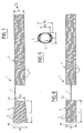
- Figure 1 is a side view of a first embodiment of a urethral prosthesis according to the invention.
- Figure 2 is a view similar to Figure 1, but rotated 90 ° relative to the latter.
- FIG. 3 is a view along arrow III of FIG. 1.
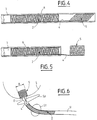
- Figure 4 shows the urethral prosthesis of Figure 1 inserted into a delivery tube.
- Figure 5 is similar to Figure 4, but with the holding device out of the tube.
- FIG. 6 illustrates the urethral prosthesis according to FIG. 1, placed in the urethra of a patient.
- Figure 7 is a side view of a variant of the first embodiment of a urethral prosthesis according to the invention.
- Figure 8 is a view similar to Figure 7, but rotated 90 ° relative to the latter.
- FIG. 9 is a view along arrow IX of FIG. 7.
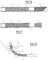
- Figure 10 shows the urethral prosthesis of Figure 7 inserted into a delivery tube.
- Figure 11 is similar to Figure 10, but with the holder out of the tube.
- FIG. 12 illustrates the urethral prosthesis according to FIG. 7, placed in the urethra of a patient.
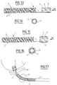
- Figure 13 is a side view of a second embodiment of a urethral prosthesis according to the invention, the holding device, made of a shape memory alloy, is in the retracted position.
- FIG. 14 is a view along arrow XIV of FIG. 13.
- Figure 15 is a view similar to Figure 13, the holding device being, in this case, in the expanded position.
- FIG. 16 is a view along arrow XVI of FIG. 15.
- FIG. 17 illustrates the urethral prosthesis according to FIGS. 13 and 15, placed in the urethra of a patient.
- FIG. 1 there is shown, in side view, a first embodiment of a urethral prosthesis 1 according to the invention.
- the prosthesis 1 comprises a first part 2 in the form of a first helical spring with contiguous turns 3, constituting the prosthesis itself, intended to be housed in the bulb-membranous urethra U at the level of a Stenosis St (FIG. 6) .
- the spring 2 of circular section may have a constant outside diameter of approximately 6.6 mm and a length of approximately 60 mm.
- the first spring 2 is connected, by means of a metal wire 4, to a second helical spring 5 with contiguous turns 3, intended to form the device for holding the spring 2 in the prostate or in the prostate gland L (FIG. 6).
- the metal wire 4, intended to pass through the sphincter Sp (FIG. 6), and the length of which can be of the order of 10 mm, can be formed in one piece with the first and second springs and that, moreover, the first spring 2, the metal wire 4, and the second spring 5 are advantageously made of a stainless metal of medical quality.
- the second spring 5 is shorter than the first spring 2 and can have, for example, a length of around 15 mm.
- the second spring 5 has an oblong shape in cross section ( Figure 3), substantially elliptical or in the shape of an "athletic track". ".
- the large “axis” A of this "ellipse” may have a length of approximately 10 mm, and its small “axis” B a length of approximately 6.6 mm. It will be noted that, in this case, this oblong cross section is constant over the entire length L of the second spring 5.
- the prosthesis 1 can be introduced into the positioning tube 6 (constituting standard equipment with a determined internal diameter corresponding to the external diameter of the spring 2) by tilting the oblong turns of the spring 5. This is possible because the "width" of the oblong cross section of the spring 5 is equal to the diameter of the spring 2.
- the spring 5 "inclined” in the tube resumes its initial shape when leaving the latter ( Figure 5).
- the length B of the large "axis" of the cross section of the spring 5 is sufficient to maintain the position of the spring 2 in the urethra U at the level of the stenosis St, by pressing on the edge of the opening 0 of the urethra U opening into the prostate gland L.
- Bo is equal to A.
- This configuration of the second spring 5 likewise allows the introduction of the prosthesis 1 into the positioning tube 6 (FIG. 10) by tilting the oblong turns of the spring 5, which returns to its initial shape when leaving the tube 6 under the action of pusher 7 (FIG. 11).
- the spring 2 is then held in position in the urethra U at the level of the stenosis St, by pressing the spring 5 in the vicinity of the opening 0 of the urethra U emerging in the prostate gland L, the proximal end portion of the spring 5 sinking slightly into the urethra U until it is blocked when the increase in length B, towards the distal end of the spring 5, is sufficient.
- the spring 2 is connected, by means of a metal wire 4, intended to pass through the sphincter Sp, to a device 8 for holding the spring 2 in position in the urethra U at the level of the stenosis St, which device consists of a ring 8 of shape memory alloy, having longitudinal openings 9 facilitating its radial expansion, and which can be covered by a sheath 10 of synthetic material, in particular of silicone, open at both ends to guarantee the passage of fluids through the ring 8.
- the ring 8 guarantees the maintenance in position of the spring 2 by bearing in the vicinity of the edge of the opening 0 of the urethra U opening into the prostate gland L ( Figure 17).
- the openings 9 are intended to facilitate the radial expansion of the ring 8 and to increase the percentage of increase in diameter of the ring. If the latter did not have such openings, the percentage of radial expansion of the ring would be around 8%, while, by providing the openings 9, it is possible to reach percentages of radial expansion of up to 100%. or even 200%, because the expansion is, in this case, a function of the length of the tube forming the ring 8 and of the openings and no longer of the nature of the material used.
- the ring In addition, to avoid any tissue proliferation inside the ring, it can be covered with a silicone sheath which also ensures better biocompatibility of the assembly.
- the shape memory alloy ring When placing the prosthesis, the shape memory alloy ring has the same outside diameter as the rest of the prosthesis. When the prosthesis is in place in the urethra, the ring can then be heated to cause its radial expansion in the prostate gland. Different types of heaters can be used: liquid source, laser beam, high frequency induction, insulated electric heating sleeve. For the removal of the prosthesis, another characteristic of the shape memory alloys is used, which become malleable at temperatures of about 10 to 15 ° C. In situ cooling must be carried out before removing the prosthesis.
- the shape memory alloys may be selected in a non-exhaustive manner from the families: Ti Ni, Cu Zn Al, Cu Al Ni or Fe Mn.
- the shape memory alloy will also be chosen to present a resumption of austenitic hot shape at a temperature higher than that of the human body.
- the temperature at the start of transformation (As) will be chosen around 37 ° C and the temperature at the end of transformation (Af) as close as possible to the temperature at the start of transformation (appearance austenite).
- in situ fluid cooling is provided.
- Mf the temperature at which all traces of austenitic phase has disappeared
- the invention is not limited to the described embodiments of a urethral prosthesis.
- the holding device of the invention can be used to hold and immobilize in position any analogous prosthesis in a body channel of similar type.
Abstract
Description
- La présente invention concerne une prothèse destinée à être introduite dans un canal corporel.
- On connaît, par exemple, une prothèse urétrale amovible pour le traitement des sténoses récidivantes dans l'urètre bulbo-membraneux. Cette prothèse a pour but de maintenir ouvert l'urètre pendant la cicatrisation après l'urétrotomie et sert ainsi de support à la cicatrisation de la paroi urétrale. Cette prothèse comporte deux parties, se présentant chacune sous forme d'un ressort hélicoïdal à spires jointives. Ces deux ressorts ont un même diamètre et des longueurs différentes et sont reliés l'un à l'autre par un fil métallique. Le ressort le plus long sert de prothèse proprement dite, maintenant l'urètre ouvert au diamètre du ressort, tandis que le ressort le plus court, relié à l'extrémité distale du ressort le plus long, permet d'immobiliser ce dernier en position par fixation dans la prostate. Toutefois, dans certains cas, cette prothèse a tendance à descendre dans l'urètre car la fixation dans la prostate par simple serrage n'est pas toujours suffisante, par exemple quand l'urètre prostatique est trop large. De plus, quand la prostate a été réséquée ou après une prostatectomie, une prothèse telle que définie ci-dessus ne peut pas être utilisée.
- La présente invention a pour but d'éviter ces inconvénients, et concerne une prothèse adaptée pour pouvoir être immobilisée en position, de façon positive, dans un canal corporel.
- A cet effet, la prothèse destinée à être introduite dans un canal corporel, comportant un tube flexible destiné à conserver la section normale de passage du canal corporel et constituant la prothèse proprement dite, et un dispositif de maintien destiné à immobiliser en position ledit tube dans ledit canal, ledit dispositif étant relié à l'extrémité distale dudit tube par des moyens de liaison, en étant agencé à distance de ladite extrémité, est remarquable, selon l'invention, en ce que le dispositif de maintien est constitué par une structure radialement déformable susceptible de passer d'un premier état dans lequel sa section transversale est au plus égale à celle du canal corporel dans lequel elle doit être introduite, à un second état dans lequel sa section transversale est telle que ladite structure peut prendre appui sur la paroi interne du canal corporel, notamment au voisinage du bord d'un orifice du canal corporel débouchant dans une cavité naturelle et, inversement, de passer dudit second état audit premier état.
- Ainsi, grâce à cette structure radialement déformable du dispositif de maintien, ce dernier peut être introduit, avec la prothèse proprement dite, sans problème dans le canal corporel et, lorsque la prothèse est mise en place, le dispositif de maintien immobilise en position, de façon positive, la prothèse (tube flexible), après être passé dans son second état, par appui et blocage sur le canal corporel au diamètre duquel il peut s'adapter.
- Selon un premier exemple de réalisation de la prothèse de l'invention, ladite structure est un ressort hélicoïdal, présentant une section transversale de forme oblongue, dont la petite dimension est au plus égale au diamètre intérieur du canal corporel.
- Dans ce cas, pour l'introduction dans le canal corporel, les spires oblongues du ressort peuvent être inclinées de sorte que leur grande dimension ne présente plus, dans le canal, qu'une "hauteur" correspondant au diamètre interne de ce dernier, y compris le tube d'introduction de la prothèse. Une fois la prothèse en place, les spires oblongues reviennent en position initiale, ce qui permet alors d'immobiliser positivement la prothèse dans le canal.
- De préférence, les spires dudit ressort sont au moins sensiblement jointives.
- Selon une première variante de cet exemple de réalisation, la section transversale oblongue dudit ressort est constante sur toute la longueur de ce dernier, tandis que, selon une seconde variante, la grande dimension de la section transversale oblongue dudit ressort croît progressivement de l'extrémité proximale à l'extrémité distale de ce dernier.
- De plus, ledit ressort peut être réalisé en fil métallique de qualité médicale.
- Selon un second exemple de réalisation de la prothèse de l'invention, ladite structure est une bague en alliage à mémoire de forme, susceptible d'expansion radiale selon la température à laquelle elle est portée.
- La bague présente un diamètre initial autorisant son introduction dans le canal corporel. En chauffant, une fois la prothèse mise en place, la bague subit une expansion radiale permettant d'immobiliser la prothèse en position, selon le même principe que précédemment.
- Avantageusement, ladite bague présente des ouvertures longitudinales facilitant son expansion radiale.
- De préférence, ladite bague est recouverte par une gaine de matière synthétique, ouverte aux deux extrémités, réalisée notamment en silicone.
- De plus, ledit tube flexible peut être un ressort hélicoïdal, à spires au moins sensiblement jointives, de section transversale circulaire, tandis que lesdits moyens de liaison peuvent être constitués par un fil métallique.
- Les figures du dessin annexé feront bien comprendre comment l'invention peut être réalisée. Sur ces figures, des références identiques désignent des éléments semblables.
- La figure 1 est une vue de côté d'un premier exemple de réalisation d'une prothèse urétrale selon l'invention.
- La figure 2 est une vue semblable à la figure 1, mais tournée de 90° par rapport à cette dernière.
- La figure 3 est une vue selon la flèche III de la figure 1.
- La figure 4 montre la prothèse urétrale de la figure 1 insérée dans un tube de mise en place.
- La figure 5 est semblable à la figure 4, mais avec le dispositif de maintien sorti du tube.
- La figure 6 illustre la prothèse urétrale selon la figure 1, mise en place dans l'urètre d'un patient.
- La figure 7 est une vue de côté d'une variante du premier exemple de réalisation d'une prothèse urétrale selon l'invention.
- La figure 8 est une vue semblable à la figure 7, mais tournée de 90° par rapport à cette dernière.
- La figure 9 est une vue selon la flèche IX de la figure 7.
- La figure 10 montre la prothèse urétrale de la figure 7 insérée dans un tube de mise en place.
- La figure 11 est semblable à la figure 10, mais avec le dispositif de maintien sorti du tube.
- La figure 12 illustre la prothèse urétrale selon la figure 7, mise en place dans l'urètre d'un patient.
- La figure 13 est une vue de côté d'un second exemple de réalisation d'une prothèse urétrale selon l'invention, dont le dispositif de maintien, réalisé en un alliage à mémoire de forme, est en position rétractée.
- La figure 14 est une vue selon la flèche XIV de la figure 13.
- La figure 15 est une vue semblable à la figure 13, le dispositif de maintien étant, dans ce cas, en position expansée.
- La figure 16 est une vue selon la flèche XVI de la figure 15.
- La figure 17 illustre la prothèse urétrale selon les figures 13 et 15, mise en place dans l'urètre d'un patient.
- Sur la figure 1, on a représenté, en vue de côté, un premier exemple de réalisation d'une prothèse urétrale 1 conforme à l'invention. La prothèse 1 comporte une première partie 2 sous forme d'un premier ressort hélicoïdal à spires jointives 3, constituant la prothèse proprement dite, destinée à être logée dans l'urètre bulbo-membraneux U au niveau d'une sténose St (figure 6). A titre d'exemple non limitatif et pour donner un ordre de grandeur, le ressort 2 de section circulaire peut présenter un diamètre extérieur constant d'environ 6,6 mm et une longueur d'environ 60 mm. Le premier ressort 2 est relié, par l'intermédiaire d'un fil métallique 4, à un second ressort hélicoïdal 5 à spires jointives 3, destiné à former le dispositif de maintien du ressort 2 dans la prostate ou dans la loge prostatique L (figure 6). On notera que, comme représenté, le fil métallique 4, destiné à traverser le sphincter Sp (figure 6), et dont la longueur peut être de l'ordre de 10 mm, peut être formé en une seule pièce avec les premier et second ressorts et que, par ailleurs, le premier ressort 2, le fil métallique 4, et le second ressort 5 sont avantageusement réalisés en un métal inoxydable de qualité médicale.
- Le second ressort 5 est plus court que le premier ressort 2 et peut présenter, par exemple, une longueur d'environ 15 mm. De plus, selon l'invention et contrairement au premier ressort 2 présentant une section transversale circulaire (figure 3), le second ressort 5 présente une forme oblongue en section transversale (figure 3), sensiblement elliptique ou en forme de "piste d'athlétisme". A titre d'exemple non limitatif, le grand "axe" A de cette "ellipse" peut présenter une longueur d'environ 10 mm, et son petit "axe" B une longueur d'environ 6,6 mm. On notera que, dans ce cas, cette section transversale oblongue est constante sur toute la longueur L du second ressort 5.
- Comme le montre la figure 4, la prothèse 1 peut être introduite dans le tube de mise en place 6 (constituant un équipement standard d'un diamètre intérieur déterminé correspondant au diamètre extérieur du ressort 2) en inclinant les spires oblongues du ressort 5. Cela est possible du fait que la "largeur" de la section transversale oblongue du ressort 5 est égale au diamètre du ressort 2. Au moment de la mise en place de la prothèse dans l'urètre, à l'aide du poussoir 7, le ressort 5 "incliné" dans le tube reprend sa forme initiale en sortant de ce dernier (figure 5).
- Comme on le voit sur la figure 6, une fois le tube de mise en place 6 retiré, la longueur B du grand "axe" de la section transversale du ressort 5 est suffisante pour assurer le maintien en position du ressort 2 dans l'urètre U au niveau de la sténose St, par appui sur le bord de l'ouverture 0 de l'urètre U débouchant dans la loge prostatique L.
- La variante du premier exemple de réalisation de la prothèse urétrale 1, montrée sur les figures 7 à 12, ne diffère de la prothèse des figures 1 à 6 que par le fait que, dans ce cas, le second ressort 5 présente une forme sensiblement tronconique de section transversale également sensiblement elliptique ou en forme de "piste d'athlétisme", mais dont le grand "axe" B croît progressivement (par exemple de 6,6 mm à 10 mm) de l'extrémité proximale 5a (Bo) du ressort 5 en regard du ressort 2 à son extrémité distale opposée 5b (B1), tandis que le petit "axe" A (égal au diamètre du ressort 2) reste constant sur toute la longueur L du ressort 5 (voir les figures 7 à 9). On notera qu'en fait, à l'extrémité 5a, Bo est égal à A.
- Cette configuration du second ressort 5 permet de même l'introduction de la prothèse 1 dans le tube de mise en place 6 (figure 10) en inclinant les spires oblongues du ressort 5, lequel reprend sa forme initiale en sortant du tube 6 sous l'action du poussoir 7 (figure 11).
- Par ailleurs, comme on le voit sur la figure 12, le ressort 2 est alors maintenu en position dans l'urètre U au niveau de la sténose St, par appui du ressort 5 au voisinage de l'ouverture 0 de l'urètre U débouchant dans la loge prostatique L, la partie d'extrémité proximale du ressort 5 s'enfonçant légèrement dans l'urètre U jusqu'à être bloquée lorsque l'augmentation de la longueur B, vers l'extrémité distale du ressort 5, est suffisante.
- Dans le second exemple de réalisation de la prothèse urétrale 1, représenté sur les figures 13 à 17, on retrouve le ressort hélicoïdal 2 à spires jointives 3, de section circulaire et de diamètre constant, destiné à former la prothèse proprement dite dans l'urètre U au niveau de la sténose St. Cependant, dans ce cas, le ressort 2 est relié, par l'intermédiaire d'un fil métallique 4, destiné à traverser le sphincter Sp, à un dispositif de maintien 8 du ressort 2 en position dans l'urètre U au niveau de la sténose St, lequel dispositif est constitué par une bague 8 en alliage à mémoire de forme, présentant des ouvertures longitudinales 9 facilitant son expansion radiale, et pouvant être recouverte par une gaine 10 de matière synthétique, notamment de silicone, ouverte aux deux extrémités pour garantir le passage de fluides à travers la bague 8. Dans l'état expansé, la bague 8 garantit le maintien en position du ressort 2 en prenant appui au voisinage du bord de l'ouverture 0 de l'urètre U débouchant dans la loge prostatique L (figure 17).
- Les ouvertures 9 ont pour but de faciliter l'expansion radiale de la bague 8 et d'augmenter le pourcentage d'augmentation de diamètre de la bague. Si celle-ci n'avait pas de telles ouvertures, le pourcentage d'expansion radiale de la bague serait d'environ 8 %, alors que, en prévoyant les ouvertures 9, on peut atteindre des pourcentages d'expansion radiale pouvant atteindre 100 % ou même 200 %, car l'expansion est, dans ce cas, fonction de la longueur du tube formant la bague 8 et des ouvertures et non plus de la nature du matériau employé.
- De plus, pour éviter toute prolifération tissulaire à l'intérieur de la bague, celle-ci peut être recouverte d'une gaine de silicone qui assure aussi une meilleure biocompatibilité de l'ensemble.
- Lors de la mise en place de la prothèse, la bague en alliage à mémoire de forme présente le même diamètre extérieur que le reste de la prothèse. Quand la prothèse est en place dans l'urètre, la bague peut alors être chauffée pour provoquer son expansion radiale dans la loge prostatique. Différents types de chauffages peuvent être utilisés : source liquide, faisceau laser, induction à haute fréquence, manchon électrique chauffant isolé. Pour le retrait de la prothèse, on utilise une autre caractéristique des alliages à mémoire de forme, qui deviennent malléables à des températures d'environ 10 à 15°C. Un refroidissement in situ devra être réalisé avant le retrait de la prothèse.
- Les alliages à mémoire de forme pourront être sélectionnés de façon non exhaustive dans les familles : Ti Ni, Cu Zn Al, Cu Al Ni ou Fe Mn.
- L'alliage à mémoire de forme sera de plus choisi pour présenter une reprise de forme chaude austénitique à une température supérieure à celle du corps humain. Pour faciliter la manipulation et respecter les tissus environnants, la température du début de transformation (As) sera choisie aux environs de 37°C et la température de fin de transformation (Af) aussi proche que possible de la température du début de transformation (apparition de l'austénite). De façon à pouvoir retirer la bague en alliage à mémoire de forme, il est prévu un refroidissement in situ par fluide. Pour faciliter la manipulation et respecter les tissus environnants, la température pour laquelle toute trace de phase austénitique a disparu (Mf) sera choisie aussi élevée que possible (réduction de l'hystérésis). Dès qu'elle est refroidie à une température inférieure à la température Mf, la bague redevient malléable et peut être retirée.
- On notera par ailleurs que l'utilisation d'une bague en alliage à mémoire de forme ayant la caractéristique de superélasticité à la température du corps humain, permettrait d'insérer la bague sans contrainte de chauffage et de la retirer sans refroidissement. Un dispositif de bridage de la bague à son diamètre minimal serait utilisé pendant la mise en place de la prothèse, ainsi que pour l'extraction de la bague.
- Il est bien entendu que l'invention n'est pas limitée aux exemples de réalisation décrits d'une prothèse urétrale. En fait, le dispositif de maintien de l'invention peut être utilisé pour maintenir et immobiliser en position toute prothèse analogue dans un canal corporel de type semblable.
Claims (12)
- Prothèse destinée à être introduite dans un canal corporel, comportant un tube flexible (2) destiné à conserver la section normale de passage du canal corporel et constituant la prothèse proprement dite, et un dispositif de maintien (5,8) destiné à immobiliser en position ledit tube (2) dans ledit canal (U), ledit dispositif (5,8) étant relié à l'extrémité distale dudit tube (2) par des moyens de liaison (4), en étant agencé à distance de ladite extrémité,
caractérisée en ce que le dispositif de maintien est constitué par une structure (5,8) radialement déformable susceptible de passer d'un premier état dans lequel sa section transversale est au plus égale à celle du canal corporel (U) dans lequel elle doit être introduite, à un second état dans lequel sa section transversale est telle que ladite structure (5,8) peut prendre appui sur la paroi interne du canal corporel, notamment au voisinage du bord d'un orifice du canal corporel (U) débouchant dans une cavité naturelle et, inversement, de passer dudit second état audit premier état. - Prothèse selon la revendication 1,
caractérisée en ce que ladite structure est un ressort hélicoïdal (5), présentant une section transversale de forme oblongue, dont la petite dimension (A) est au plus égale au diamètre intérieur du canal corporel (U). - Prothèse selon la revendication 2,
caractérisée en ce que les spires (3) dudit ressort (5) sont au moins sensiblement jointives. - Prothèse selon la revendication 2 ou la revendication 3,
caractérisée en ce que la section transversale oblongue dudit ressort (5) est constante sur toute la longueur de ce dernier. - Prothèse selon la revendication 2 ou la revendication 3,
caractérisée en ce que la grande dimension (B) de la section transversale oblongue dudit ressort (5) croît progressivement de l'extrémité proximale (5a) à l'extrémité distale (5b) de ce dernier. - Prothèse selon l'une quelconque des revendications 2 à 5,
caractérisée en ce que ledit ressort (5) est réalisé en fil métallique de qualité médicale. - Prothèse selon la revendication 1,
caractérisée en ce que ladite structure est une bague (8) en alliage à mémoire de forme, susceptible d'expansion radiale selon la température à laquelle elle est portée. - Prothèse selon la revendication 7,
caractérisée en ce que ladite bague (8) présente des ouvertures longitudinales (9) facilitant son expansion radiale. - Prothèse selon la revendication 7 ou la revendication 8,
caractérisée en ce que ladite bague (8) est recouverte par une gaine (10) de matière synthétique, ouverte aux deux extrémités. - Prothèse selon la revendication 9,
caractérisée en ce que ladite gaine (10) est réalisée en silicone. - Prothèse selon l'une quelconque des revendications 1 à 10,
caractérisée en ce que ledit tube flexible est un ressort hélicoïdal (2), à spires (3) au moins sensiblement jointives, de section transversale circulaire. - Prothèse selon l'une quelconque des revendications 1 à 11,
caractérisée en ce que lesdits moyens de liaison sont constitués par un fil métallique (4).
Applications Claiming Priority (2)
| Application Number | Priority Date | Filing Date | Title |
|---|---|---|---|
| FR9307693A FR2706764B1 (fr) | 1993-06-24 | 1993-06-24 | |
| FR9307693 | 1993-06-24 |
Publications (2)
| Publication Number | Publication Date |
|---|---|
| EP0631762A1 true EP0631762A1 (fr) | 1995-01-04 |
| EP0631762B1 EP0631762B1 (fr) | 2002-07-31 |
Family
ID=9448509
Family Applications (1)
| Application Number | Title | Priority Date | Filing Date |
|---|---|---|---|
| EP94401147A Expired - Lifetime EP0631762B1 (fr) | 1993-06-24 | 1994-05-25 | Prothèse pour canal corporel |
Country Status (7)
| Country | Link |
|---|---|
| US (1) | US5514178A (fr) |
| EP (1) | EP0631762B1 (fr) |
| JP (1) | JP3321494B2 (fr) |
| AT (1) | ATE221347T1 (fr) |
| DE (1) | DE69431090T2 (fr) |
| ES (1) | ES2177567T3 (fr) |
| FR (1) | FR2706764B1 (fr) |
Cited By (4)
| Publication number | Priority date | Publication date | Assignee | Title |
|---|---|---|---|---|
| FR2767673A1 (fr) * | 1997-08-27 | 1999-03-05 | Synthelabo | Prothese uretrale |
| WO2007062661A2 (fr) * | 2005-12-02 | 2007-06-07 | Pnn Medical A/S | Endoprothese vasculaire |
| EP1920740A3 (fr) * | 2006-11-09 | 2009-06-24 | Olympus Medical Systems Corp. | Instrument d'approvisionnement d'endoprothèse vasculaire |
| EP3116583A4 (fr) * | 2014-03-14 | 2017-10-25 | The Board of Trustees of The Leland Stanford Junior University | Dispositif d'expansion de lumière à demeure |
Families Citing this family (80)
| Publication number | Priority date | Publication date | Assignee | Title |
|---|---|---|---|---|
| US5549559A (en) | 1990-03-22 | 1996-08-27 | Argomed Ltd. | Thermal treatment apparatus |
| FR2701648B1 (fr) * | 1993-02-19 | 1995-03-31 | Marian Devonec | Prothèse destinée au traitement d'une lumière ou voie naturelle, notamment prothèse endo-uréthrale. |
| US6576008B2 (en) * | 1993-02-19 | 2003-06-10 | Scimed Life Systems, Inc. | Methods and device for inserting and withdrawing a two piece stent across a constricting anatomic structure |
| US5609605A (en) * | 1994-08-25 | 1997-03-11 | Ethicon, Inc. | Combination arterial stent |
| WO1996028116A1 (fr) | 1995-03-10 | 1996-09-19 | Cardiovascular Concepts, Inc. | Prothese endoluminale tubulaire a extremite obliques |
| US6991614B2 (en) | 1995-11-07 | 2006-01-31 | Boston Scientific Scimed, Inc. | Ureteral stent for improved patient comfort |
| US6576009B2 (en) | 1995-12-01 | 2003-06-10 | Medtronic Ave, Inc. | Bifurcated intraluminal prostheses construction and methods |
| US5824040A (en) | 1995-12-01 | 1998-10-20 | Medtronic, Inc. | Endoluminal prostheses and therapies for highly variable body lumens |
| US6702846B2 (en) * | 1996-04-09 | 2004-03-09 | Endocare, Inc. | Urological stent therapy system and method |
| US7686846B2 (en) * | 1996-06-06 | 2010-03-30 | Devax, Inc. | Bifurcation stent and method of positioning in a body lumen |
| US7238197B2 (en) * | 2000-05-30 | 2007-07-03 | Devax, Inc. | Endoprosthesis deployment system for treating vascular bifurcations |
| US8728143B2 (en) * | 1996-06-06 | 2014-05-20 | Biosensors International Group, Ltd. | Endoprosthesis deployment system for treating vascular bifurcations |
| US6666883B1 (en) | 1996-06-06 | 2003-12-23 | Jacques Seguin | Endoprosthesis for vascular bifurcation |
| US6835203B1 (en) | 1996-11-04 | 2004-12-28 | Advanced Stent Technologies, Inc. | Extendible stent apparatus |
| US8211167B2 (en) | 1999-12-06 | 2012-07-03 | Boston Scientific Scimed, Inc. | Method of using a catheter with attached flexible side sheath |
| US7341598B2 (en) * | 1999-01-13 | 2008-03-11 | Boston Scientific Scimed, Inc. | Stent with protruding branch portion for bifurcated vessels |
| US7591846B2 (en) | 1996-11-04 | 2009-09-22 | Boston Scientific Scimed, Inc. | Methods for deploying stents in bifurcations |
| ES2273363T3 (es) | 1996-11-04 | 2007-05-01 | Advanced Stent Technologies, Inc. | Doble stent extensible. |
| US6692483B2 (en) | 1996-11-04 | 2004-02-17 | Advanced Stent Technologies, Inc. | Catheter with attached flexible side sheath |
| US6080160A (en) * | 1996-12-04 | 2000-06-27 | Light Sciences Limited Partnership | Use of shape memory alloy for internally fixing light emitting device at treatment site |
| US5964732A (en) * | 1997-02-07 | 1999-10-12 | Abbeymoor Medical, Inc. | Urethral apparatus with position indicator and methods of use thereof |
| US5971967A (en) | 1997-08-19 | 1999-10-26 | Abbeymoor Medical, Inc. | Urethral device with anchoring system |
| US6071308A (en) | 1997-10-01 | 2000-06-06 | Boston Scientific Corporation | Flexible metal wire stent |
| US5893887A (en) * | 1997-10-14 | 1999-04-13 | Iowa-India Investments Company Limited | Stent for positioning at junction of bifurcated blood vessel and method of making |
| US5989207A (en) * | 1997-11-03 | 1999-11-23 | Hughes; Boyd R. | Double swirl stent |
| US5916195A (en) * | 1998-02-04 | 1999-06-29 | Argomed Ltd. | Internal catheter |
| US6893430B2 (en) | 1998-02-04 | 2005-05-17 | Wit Ip Corporation | Urethral catheter and guide |
| US6258098B1 (en) | 1998-05-08 | 2001-07-10 | William N. Taylor | Stent placement and removal system |
| US6652569B1 (en) | 1998-05-08 | 2003-11-25 | Biu Biomedical Innovations (Urology) Inc. | Stent placement and removal |
| US6494879B2 (en) | 1998-10-15 | 2002-12-17 | Scimed Life Systems, Inc. | Treating urinary retention |
| US7655030B2 (en) * | 2003-07-18 | 2010-02-02 | Boston Scientific Scimed, Inc. | Catheter balloon systems and methods |
| US6332892B1 (en) | 1999-03-02 | 2001-12-25 | Scimed Life Systems, Inc. | Medical device with one or more helical coils |
| US6319237B1 (en) | 1999-04-23 | 2001-11-20 | Icd Labs, Inc. | Urinary sphincter control device |
| US6884258B2 (en) | 1999-06-04 | 2005-04-26 | Advanced Stent Technologies, Inc. | Bifurcation lesion stent delivery using multiple guidewires |
| US7044980B2 (en) * | 2000-02-03 | 2006-05-16 | Boston Scientific Scimed, Inc. | Facilitating drainage |
| US20030139803A1 (en) * | 2000-05-30 | 2003-07-24 | Jacques Sequin | Method of stenting a vessel with stent lumenal diameter increasing distally |
| US6716252B2 (en) | 2000-06-30 | 2004-04-06 | Wit Ip Corporation | Prostatic stent with localized tissue engaging anchoring means and methods for inhibiting obstruction of the prostatic urethra |
| JP2004529676A (ja) | 2000-11-13 | 2004-09-30 | ダブリュ アイ ティー アイ ピー コーポレーション | 断熱領域を有する治療カテーテル |
| US20020124851A1 (en) * | 2000-11-28 | 2002-09-12 | Richard Knauer | Hearing protective device and method of making same |
| WO2002058541A2 (fr) * | 2001-01-23 | 2002-08-01 | Abbeymoor Medical, Inc. | Dispositif et procede endo-uretral |
| JP3910020B2 (ja) * | 2001-03-08 | 2007-04-25 | 敏行 ▲高▼木 | 人工括約筋 |
| US6719804B2 (en) | 2001-04-02 | 2004-04-13 | Scimed Life Systems, Inc. | Medical stent and related methods |
| US6685745B2 (en) * | 2001-05-15 | 2004-02-03 | Scimed Life Systems, Inc. | Delivering an agent to a patient's body |
| US6494855B2 (en) * | 2001-05-16 | 2002-12-17 | Scimed Life Systems, Inc. | Draining bodily fluid |
| US8617231B2 (en) | 2001-05-18 | 2013-12-31 | Boston Scientific Scimed, Inc. | Dual guidewire exchange catheter system |
| US6981964B2 (en) * | 2001-05-22 | 2006-01-03 | Boston Scientific Scimed, Inc. | Draining bodily fluids with a stent |
| US6620202B2 (en) | 2001-10-16 | 2003-09-16 | Scimed Life Systems, Inc. | Medical stent with variable coil and related methods |
| US8506647B2 (en) * | 2002-02-14 | 2013-08-13 | Boston Scientific Scimed, Inc. | System for maintaining body canal patency |
| US8328877B2 (en) | 2002-03-19 | 2012-12-11 | Boston Scientific Scimed, Inc. | Stent retention element and related methods |
| US20030195609A1 (en) * | 2002-04-10 | 2003-10-16 | Scimed Life Systems, Inc. | Hybrid stent |
| US6733536B1 (en) * | 2002-10-22 | 2004-05-11 | Scimed Life Systems | Male urethral stent device |
| CA2505137A1 (fr) * | 2002-11-08 | 2004-05-21 | Jacques Seguin | Prothese endovasculaire en bifurcation |
| US8282678B2 (en) * | 2002-11-13 | 2012-10-09 | Allium Medical Solutions Ltd. | Endoluminal lining |
| DE10255344A1 (de) * | 2002-11-27 | 2005-06-30 | Siemens Ag | Fördersystem für Güter, insbesondere Behälter für Gepäckstücke, und Steuerverfahren für das Fördersystem |
| US6929663B2 (en) * | 2003-03-26 | 2005-08-16 | Boston Scientific Scimed, Inc. | Longitudinally expanding medical device |
| US20040199246A1 (en) * | 2003-04-02 | 2004-10-07 | Scimed Life Systems, Inc. | Expandable stent |
| US7651529B2 (en) * | 2003-05-09 | 2010-01-26 | Boston Scientific Scimed, Inc. | Stricture retractor |
| US8048169B2 (en) * | 2003-07-28 | 2011-11-01 | Baronova, Inc. | Pyloric valve obstructing devices and methods |
| US9498366B2 (en) * | 2003-07-28 | 2016-11-22 | Baronova, Inc. | Devices and methods for pyloric anchoring |
| US9700450B2 (en) | 2003-07-28 | 2017-07-11 | Baronova, Inc. | Devices and methods for gastrointestinal stimulation |
| US20090259236A2 (en) * | 2003-07-28 | 2009-10-15 | Baronova, Inc. | Gastric retaining devices and methods |
| US8821521B2 (en) * | 2003-07-28 | 2014-09-02 | Baronova, Inc. | Gastro-intestinal device and method for treating addiction |
| US8298280B2 (en) | 2003-08-21 | 2012-10-30 | Boston Scientific Scimed, Inc. | Stent with protruding branch portion for bifurcated vessels |
| US7766899B2 (en) * | 2003-09-17 | 2010-08-03 | Prostalund Operations Ab | Partial-length, indwelling prostatic catheter using coiled inflation tube as an anchor and methods of draining urine and flushing clots |
| US7344557B2 (en) | 2003-11-12 | 2008-03-18 | Advanced Stent Technologies, Inc. | Catheter balloon systems and methods |
| US8123762B2 (en) | 2004-08-19 | 2012-02-28 | Boston Scientific Scimed, Inc. | Suturing instrument |
| DE202005001416U1 (de) | 2005-01-28 | 2005-03-31 | Urovision Ges Fuer Medizinisch | Stent |
| CA2613044A1 (fr) * | 2005-06-20 | 2007-01-04 | Abbeymoor Medical, Inc. | Article pour distribuer un medicament, accessoire et systeme |
| EP2243507A1 (fr) * | 2005-10-29 | 2010-10-27 | PNN Medical SA | Endoprothèse avec portion d'ancrage |
| US8821561B2 (en) | 2006-02-22 | 2014-09-02 | Boston Scientific Scimed, Inc. | Marker arrangement for bifurcation catheter |
| US8486134B2 (en) | 2007-08-01 | 2013-07-16 | Boston Scientific Scimed, Inc. | Bifurcation treatment system and methods |
| WO2009033049A1 (fr) * | 2007-09-07 | 2009-03-12 | Baronova, Inc. | Dispositif d'obstruction intermittente d'un orifice gastrique et son procédé d'utilisation |
| WO2009088953A2 (fr) | 2007-12-31 | 2009-07-16 | Boston Scientific Scimed Inc. | Système et procédés de pose de prothèse endovasculaire à bifurcation |
| US8377108B2 (en) | 2008-06-02 | 2013-02-19 | Boston Scientific Scimed, Inc. | Staggered two balloon bifurcation catheter assembly and methods |
| US8827954B2 (en) | 2008-06-05 | 2014-09-09 | Boston Scientific Scimed, Inc. | Deflatable bifurcated device |
| WO2009149405A1 (fr) | 2008-06-05 | 2009-12-10 | Boston Scientific Scimed, Inc. | Traitement de lumière bifurquée de ballonnet |
| BR112015023344B1 (pt) | 2013-03-15 | 2022-05-31 | Baronova, Inc | Dispositivo para intermitentemente obstruir uma abertura gástrica; e método de reconfiguração instalação de um dispositivo de oclusão |
| CA3046087A1 (fr) | 2016-12-09 | 2018-06-14 | Zenflow, Inc. | Systemes, dispositifs et methodes pour le deploiement precis d'un implant dans l'uretre prostatique |
| WO2019023633A1 (fr) * | 2017-07-28 | 2019-01-31 | Zenflow, Inc. | Systèmes, dispositifs et procédés pour augmenter le diamètre de l'urètre prostatique |
| AU2020387396A1 (en) | 2019-11-19 | 2022-04-21 | Zenflow, Inc. | Systems, devices, and methods for the accurate deployment and imaging of an implant in the prostatic urethra |
Citations (13)
| Publication number | Priority date | Publication date | Assignee | Title |
|---|---|---|---|---|
| DE321666C (de) * | 1912-02-28 | 1920-06-11 | Louis Marie Clement Charnaux D | Mit Drahteinlage versehene Kanuele, Sonde, Drainroehre o. dgl. rohrfoermige Vorrichtung zum aerztlichen oder hygienischen Gebrauch aus weichem Kautschuk |
| FR1576374A (fr) * | 1968-01-29 | 1969-08-01 | ||
| US4250873A (en) * | 1977-04-26 | 1981-02-17 | Richard Wolf Gmbh | Endoscopes |
| GB2172203A (en) * | 1985-03-14 | 1986-09-17 | Univ Manchester | A urethral catheter |
| WO1989001798A1 (fr) * | 1987-09-02 | 1989-03-09 | Engineers & Doctors A/S | Dispositif pour placer un catheter partiel dans une cavite corporelle |
| US4955859A (en) * | 1989-07-07 | 1990-09-11 | C. R. Bard, Inc. | High-friction prostatic stent |
| US4994066A (en) * | 1988-10-07 | 1991-02-19 | Voss Gene A | Prostatic stent |
| WO1991016005A1 (fr) * | 1990-04-19 | 1991-10-31 | Stentek Inc. | Dispositif permettant de soigner les vaisseaux retrecis |
| FR2661603A1 (fr) * | 1990-05-02 | 1991-11-08 | Coralines Abj Division Sarl | Prothese anti-stenose des canaux du corps. |
| EP0481365A1 (fr) * | 1990-10-13 | 1992-04-22 | Angiomed Ag | Dispositif pour dilater une sténose dans un conduit corporel |
| WO1992019310A1 (fr) * | 1991-04-26 | 1992-11-12 | Advanced Coronary Technology, Inc. | Dispositif de support tissulaire thermoreformable amovible |
| DE4130431A1 (de) * | 1991-09-13 | 1993-03-18 | Liselotte Dr Sachse | Harnroehrenkunststoffprothese mit metallverstaerkung |
| WO1993013824A1 (fr) * | 1992-01-20 | 1993-07-22 | Engineers & Doctors A/S | Prothese endoluminale tubulaire et dilatable par segments |
Family Cites Families (8)
| Publication number | Priority date | Publication date | Assignee | Title |
|---|---|---|---|---|
| GB2069339B (en) * | 1980-02-18 | 1983-08-10 | Keymed Medicals & Ind Equip | Endo-oesophageal tube |
| US4531933A (en) * | 1982-12-07 | 1985-07-30 | C. R. Bard, Inc. | Helical ureteral stent |
| FR2551656B1 (fr) * | 1983-09-14 | 1986-09-19 | Centre Nat Rech Scient | Dispositif de commande du debit d'un fluide, organe prothetique equipe de ce dispositif et procede de fabrication d'un tel dispositif |
| DE3836787A1 (de) * | 1988-10-28 | 1990-05-03 | Joachim Prof Dr Med Thueroff | Implantierbare hydraulische penisprothese |
| DE4104702C2 (de) * | 1991-02-15 | 1996-01-18 | Malte Neuss | Implantate für Organwege in Wendelform |
| US5269802A (en) * | 1991-09-10 | 1993-12-14 | Garber Bruce B | Prostatic stent |
| US5316023A (en) * | 1992-01-08 | 1994-05-31 | Expandable Grafts Partnership | Method for bilateral intra-aortic bypass |
| US5312415A (en) * | 1992-09-22 | 1994-05-17 | Target Therapeutics, Inc. | Assembly for placement of embolic coils using frictional placement |
-
1993
- 1993-06-24 FR FR9307693A patent/FR2706764B1/fr not_active Expired - Fee Related
-
1994
- 1994-05-25 DE DE69431090T patent/DE69431090T2/de not_active Expired - Lifetime
- 1994-05-25 EP EP94401147A patent/EP0631762B1/fr not_active Expired - Lifetime
- 1994-05-25 AT AT94401147T patent/ATE221347T1/de not_active IP Right Cessation
- 1994-05-25 ES ES94401147T patent/ES2177567T3/es not_active Expired - Lifetime
- 1994-05-27 US US08/250,577 patent/US5514178A/en not_active Expired - Lifetime
- 1994-06-24 JP JP14342194A patent/JP3321494B2/ja not_active Expired - Fee Related
Patent Citations (13)
| Publication number | Priority date | Publication date | Assignee | Title |
|---|---|---|---|---|
| DE321666C (de) * | 1912-02-28 | 1920-06-11 | Louis Marie Clement Charnaux D | Mit Drahteinlage versehene Kanuele, Sonde, Drainroehre o. dgl. rohrfoermige Vorrichtung zum aerztlichen oder hygienischen Gebrauch aus weichem Kautschuk |
| FR1576374A (fr) * | 1968-01-29 | 1969-08-01 | ||
| US4250873A (en) * | 1977-04-26 | 1981-02-17 | Richard Wolf Gmbh | Endoscopes |
| GB2172203A (en) * | 1985-03-14 | 1986-09-17 | Univ Manchester | A urethral catheter |
| WO1989001798A1 (fr) * | 1987-09-02 | 1989-03-09 | Engineers & Doctors A/S | Dispositif pour placer un catheter partiel dans une cavite corporelle |
| US4994066A (en) * | 1988-10-07 | 1991-02-19 | Voss Gene A | Prostatic stent |
| US4955859A (en) * | 1989-07-07 | 1990-09-11 | C. R. Bard, Inc. | High-friction prostatic stent |
| WO1991016005A1 (fr) * | 1990-04-19 | 1991-10-31 | Stentek Inc. | Dispositif permettant de soigner les vaisseaux retrecis |
| FR2661603A1 (fr) * | 1990-05-02 | 1991-11-08 | Coralines Abj Division Sarl | Prothese anti-stenose des canaux du corps. |
| EP0481365A1 (fr) * | 1990-10-13 | 1992-04-22 | Angiomed Ag | Dispositif pour dilater une sténose dans un conduit corporel |
| WO1992019310A1 (fr) * | 1991-04-26 | 1992-11-12 | Advanced Coronary Technology, Inc. | Dispositif de support tissulaire thermoreformable amovible |
| DE4130431A1 (de) * | 1991-09-13 | 1993-03-18 | Liselotte Dr Sachse | Harnroehrenkunststoffprothese mit metallverstaerkung |
| WO1993013824A1 (fr) * | 1992-01-20 | 1993-07-22 | Engineers & Doctors A/S | Prothese endoluminale tubulaire et dilatable par segments |
Cited By (6)
| Publication number | Priority date | Publication date | Assignee | Title |
|---|---|---|---|---|
| FR2767673A1 (fr) * | 1997-08-27 | 1999-03-05 | Synthelabo | Prothese uretrale |
| EP0906750A1 (fr) * | 1997-08-27 | 1999-04-07 | Porges | Prothèse urétrale |
| WO2007062661A2 (fr) * | 2005-12-02 | 2007-06-07 | Pnn Medical A/S | Endoprothese vasculaire |
| WO2007062661A3 (fr) * | 2005-12-02 | 2007-08-30 | Engineers & Doctors Wallsten M | Endoprothese vasculaire |
| EP1920740A3 (fr) * | 2006-11-09 | 2009-06-24 | Olympus Medical Systems Corp. | Instrument d'approvisionnement d'endoprothèse vasculaire |
| EP3116583A4 (fr) * | 2014-03-14 | 2017-10-25 | The Board of Trustees of The Leland Stanford Junior University | Dispositif d'expansion de lumière à demeure |
Also Published As
| Publication number | Publication date |
|---|---|
| EP0631762B1 (fr) | 2002-07-31 |
| FR2706764A1 (fr) | 1994-12-30 |
| JP3321494B2 (ja) | 2002-09-03 |
| JPH07136282A (ja) | 1995-05-30 |
| US5514178A (en) | 1996-05-07 |
| FR2706764B1 (fr) | 1995-08-04 |
| ES2177567T3 (es) | 2002-12-16 |
| DE69431090T2 (de) | 2003-03-27 |
| DE69431090D1 (de) | 2002-09-05 |
| ATE221347T1 (de) | 2002-08-15 |
Similar Documents
| Publication | Publication Date | Title |
|---|---|---|
| EP0631762A1 (fr) | Prothèse pour canal corporel | |
| EP0661955B1 (fr) | Kit a usage medical compose d'un filtre et de son dispositif de mise en place dans le vaisseau | |
| EP0616793B1 (fr) | Instrument médical pour l'élimination de dépÔts formés sur les parois intérieures des artères ou des veines | |
| EP0771549B1 (fr) | Filtre-cathéter | |
| EP0392927A2 (fr) | Implant vertébral pour dispositif d'ostéosynthèse | |
| EP0646364A1 (fr) | Dispositif d'implantation d'une prothèse médicale dans un conduit d'un corps humain ou animal | |
| FR2749500A1 (fr) | Dispositif permettant le traitement de conduits corporels au niveau d'une bifurcation | |
| FR2815844A1 (fr) | Support tubulaire de mise en place, par voie percutanee, d'une valve cardiaque de remplacement | |
| FR2714814A1 (fr) | Dispositif destiné à être placé dans un vaisseau avec des pattes de fixation aplaties. | |
| EP0575478A1 (fr) | Filtre anti-embolie pulmonaire perfectionne et kit de presentation et mise en place correspondante. | |
| FR2694687A1 (fr) | Prothèse vasculaire pour filtrer le sang dans un vaisseau et dispositif d'intervention pour un tel filtrage temporaire. | |
| FR2733682A1 (fr) | Endoprothese pour le traitement de stenose sur des bifurcations de vaisseaux sanguins et materiel de pose a cet effet | |
| EP0495861B1 (fr) | Filtre anti-embolie pulmonaire et kit de stockage et de pose de ce filtre | |
| EP1769777A1 (fr) | Implants intersomatiques en deux parties | |
| FR2737653A1 (fr) | Filtre definitif comportant un orifice pour le passage de dispositifs medicaux et son procede de fabrication | |
| WO1998002112A1 (fr) | Gaine filtre extensible a usage chirurgical pour veine cave ou gros vaisseaux sanguins | |
| EP0906750B1 (fr) | Prothèse urétrale | |
| FR2676355A1 (fr) | Prothese chirurgicale pour chirurgie vasculaire. | |
| WO2016139370A1 (fr) | Endoprothèse et cathéter perfectionnés | |
| EP0935976B1 (fr) | Tige flexible biocompatible destinée à être implantée dans un conduit anatomique et dispositif équipé d'une telle tige | |
| FR3087113A1 (fr) | Implant aortique de type stent, et ensemble forme de deux tels implants | |
| FR2846872A1 (fr) | Dispositif formant endoprothese presentant des extremites reduites | |
| FR3106489A1 (fr) | Dispositif de traitement d’un vaisseau sanguin | |
| FR2747574A1 (fr) | Dispositif pour maintenir un corps allonge dans un conduit notamment corporel | |
| WO2005060873A1 (fr) | Dispositif formant endoprothese presentant des extremites reduites |
Legal Events
| Date | Code | Title | Description |
|---|---|---|---|
| PUAI | Public reference made under article 153(3) epc to a published international application that has entered the european phase |
Free format text: ORIGINAL CODE: 0009012 |
|
| AK | Designated contracting states |
Kind code of ref document: A1 Designated state(s): AT BE CH DE DK ES FR GB GR IE IT LI LU MC NL PT SE |
|
| 17P | Request for examination filed |
Effective date: 19950124 |
|
| 17Q | First examination report despatched |
Effective date: 19981008 |
|
| RAP1 | Party data changed (applicant data changed or rights of an application transferred) |
Owner name: PORGES |
|
| GRAG | Despatch of communication of intention to grant |
Free format text: ORIGINAL CODE: EPIDOS AGRA |
|
| GRAG | Despatch of communication of intention to grant |
Free format text: ORIGINAL CODE: EPIDOS AGRA |
|
| GRAH | Despatch of communication of intention to grant a patent |
Free format text: ORIGINAL CODE: EPIDOS IGRA |
|
| GRAH | Despatch of communication of intention to grant a patent |
Free format text: ORIGINAL CODE: EPIDOS IGRA |
|
| GRAA | (expected) grant |
Free format text: ORIGINAL CODE: 0009210 |
|
| AK | Designated contracting states |
Kind code of ref document: B1 Designated state(s): AT BE CH DE DK ES FR GB GR IE IT LI LU MC NL PT SE |
|
| PG25 | Lapsed in a contracting state [announced via postgrant information from national office to epo] |
Ref country code: NL Free format text: LAPSE BECAUSE OF FAILURE TO SUBMIT A TRANSLATION OF THE DESCRIPTION OR TO PAY THE FEE WITHIN THE PRESCRIBED TIME-LIMIT Effective date: 20020731 Ref country code: IE Free format text: LAPSE BECAUSE OF FAILURE TO SUBMIT A TRANSLATION OF THE DESCRIPTION OR TO PAY THE FEE WITHIN THE PRESCRIBED TIME-LIMIT Effective date: 20020731 Ref country code: GR Free format text: LAPSE BECAUSE OF FAILURE TO SUBMIT A TRANSLATION OF THE DESCRIPTION OR TO PAY THE FEE WITHIN THE PRESCRIBED TIME-LIMIT Effective date: 20020731 Ref country code: AT Free format text: LAPSE BECAUSE OF FAILURE TO SUBMIT A TRANSLATION OF THE DESCRIPTION OR TO PAY THE FEE WITHIN THE PRESCRIBED TIME-LIMIT Effective date: 20020731 |
|
| REF | Corresponds to: |
Ref document number: 221347 Country of ref document: AT Date of ref document: 20020815 Kind code of ref document: T |
|
| REG | Reference to a national code |
Ref country code: GB Ref legal event code: FG4D Free format text: NOT ENGLISH Ref country code: CH Ref legal event code: EP |
|
| GBT | Gb: translation of ep patent filed (gb section 77(6)(a)/1977) |
Effective date: 20020813 |
|
| REG | Reference to a national code |
Ref country code: IE Ref legal event code: FG4D Free format text: FRENCH |
|
| REF | Corresponds to: |
Ref document number: 69431090 Country of ref document: DE Date of ref document: 20020905 |
|
| PG25 | Lapsed in a contracting state [announced via postgrant information from national office to epo] |
Ref country code: SE Free format text: LAPSE BECAUSE OF FAILURE TO SUBMIT A TRANSLATION OF THE DESCRIPTION OR TO PAY THE FEE WITHIN THE PRESCRIBED TIME-LIMIT Effective date: 20021031 Ref country code: DK Free format text: LAPSE BECAUSE OF FAILURE TO SUBMIT A TRANSLATION OF THE DESCRIPTION OR TO PAY THE FEE WITHIN THE PRESCRIBED TIME-LIMIT Effective date: 20021031 |
|
| PG25 | Lapsed in a contracting state [announced via postgrant information from national office to epo] |
Ref country code: PT Free format text: LAPSE BECAUSE OF FAILURE TO SUBMIT A TRANSLATION OF THE DESCRIPTION OR TO PAY THE FEE WITHIN THE PRESCRIBED TIME-LIMIT Effective date: 20021112 |
|
| REG | Reference to a national code |
Ref country code: ES Ref legal event code: FG2A Ref document number: 2177567 Country of ref document: ES Kind code of ref document: T3 |
|
| NLV1 | Nl: lapsed or annulled due to failure to fulfill the requirements of art. 29p and 29m of the patents act | ||
| REG | Reference to a national code |
Ref country code: IE Ref legal event code: FD4D Ref document number: 0631762E Country of ref document: IE |
|
| PG25 | Lapsed in a contracting state [announced via postgrant information from national office to epo] |
Ref country code: LU Free format text: LAPSE BECAUSE OF NON-PAYMENT OF DUE FEES Effective date: 20030525 |
|
| PG25 | Lapsed in a contracting state [announced via postgrant information from national office to epo] |
Ref country code: MC Free format text: LAPSE BECAUSE OF NON-PAYMENT OF DUE FEES Effective date: 20030531 Ref country code: LI Free format text: LAPSE BECAUSE OF NON-PAYMENT OF DUE FEES Effective date: 20030531 Ref country code: CH Free format text: LAPSE BECAUSE OF NON-PAYMENT OF DUE FEES Effective date: 20030531 Ref country code: BE Free format text: LAPSE BECAUSE OF NON-PAYMENT OF DUE FEES Effective date: 20030531 |
|
| PLBE | No opposition filed within time limit |
Free format text: ORIGINAL CODE: 0009261 |
|
| STAA | Information on the status of an ep patent application or granted ep patent |
Free format text: STATUS: NO OPPOSITION FILED WITHIN TIME LIMIT |
|
| 26N | No opposition filed |
Effective date: 20030506 |
|
| BERE | Be: lapsed |
Owner name: *PORGES Effective date: 20030531 |
|
| REG | Reference to a national code |
Ref country code: CH Ref legal event code: PL |
|
| REG | Reference to a national code |
Ref country code: GB Ref legal event code: 732E |
|
| REG | Reference to a national code |
Ref country code: FR Ref legal event code: TP |
|
| PGFP | Annual fee paid to national office [announced via postgrant information from national office to epo] |
Ref country code: ES Payment date: 20110617 Year of fee payment: 18 Ref country code: FR Payment date: 20110523 Year of fee payment: 18 |
|
| PGFP | Annual fee paid to national office [announced via postgrant information from national office to epo] |
Ref country code: GB Payment date: 20110525 Year of fee payment: 18 |
|
| PGFP | Annual fee paid to national office [announced via postgrant information from national office to epo] |
Ref country code: DE Payment date: 20110518 Year of fee payment: 18 Ref country code: IT Payment date: 20110520 Year of fee payment: 18 |
|
| GBPC | Gb: european patent ceased through non-payment of renewal fee |
Effective date: 20120525 |
|
| PG25 | Lapsed in a contracting state [announced via postgrant information from national office to epo] |
Ref country code: IT Free format text: LAPSE BECAUSE OF NON-PAYMENT OF DUE FEES Effective date: 20120525 |
|
| REG | Reference to a national code |
Ref country code: FR Ref legal event code: ST Effective date: 20130131 |
|
| REG | Reference to a national code |
Ref country code: DE Ref legal event code: R119 Ref document number: 69431090 Country of ref document: DE Effective date: 20121201 |
|
| PG25 | Lapsed in a contracting state [announced via postgrant information from national office to epo] |
Ref country code: GB Free format text: LAPSE BECAUSE OF NON-PAYMENT OF DUE FEES Effective date: 20120525 Ref country code: FR Free format text: LAPSE BECAUSE OF NON-PAYMENT OF DUE FEES Effective date: 20120531 |
|
| PG25 | Lapsed in a contracting state [announced via postgrant information from national office to epo] |
Ref country code: DE Free format text: LAPSE BECAUSE OF NON-PAYMENT OF DUE FEES Effective date: 20121201 |
|
| REG | Reference to a national code |
Ref country code: ES Ref legal event code: FD2A Effective date: 20130820 |
|
| PG25 | Lapsed in a contracting state [announced via postgrant information from national office to epo] |
Ref country code: ES Free format text: LAPSE BECAUSE OF NON-PAYMENT OF DUE FEES Effective date: 20120526 |