EP0633339A2 - Process and apparatus for forming fibers - Google Patents
Process and apparatus for forming fibers Download PDFInfo
- Publication number
- EP0633339A2 EP0633339A2 EP94115971A EP94115971A EP0633339A2 EP 0633339 A2 EP0633339 A2 EP 0633339A2 EP 94115971 A EP94115971 A EP 94115971A EP 94115971 A EP94115971 A EP 94115971A EP 0633339 A2 EP0633339 A2 EP 0633339A2
- Authority
- EP
- European Patent Office
- Prior art keywords
- resin
- fluid
- flow
- nozzle
- fiberization
- Prior art date
- Legal status (The legal status is an assumption and is not a legal conclusion. Google has not performed a legal analysis and makes no representation as to the accuracy of the status listed.)
- Granted
Links
Images


Classifications
-
- D—TEXTILES; PAPER
- D04—BRAIDING; LACE-MAKING; KNITTING; TRIMMINGS; NON-WOVEN FABRICS
- D04H—MAKING TEXTILE FABRICS, e.g. FROM FIBRES OR FILAMENTARY MATERIAL; FABRICS MADE BY SUCH PROCESSES OR APPARATUS, e.g. FELTS, NON-WOVEN FABRICS; COTTON-WOOL; WADDING ; NON-WOVEN FABRICS FROM STAPLE FIBRES, FILAMENTS OR YARNS, BONDED WITH AT LEAST ONE WEB-LIKE MATERIAL DURING THEIR CONSOLIDATION
- D04H1/00—Non-woven fabrics formed wholly or mainly of staple fibres or like relatively short fibres
- D04H1/40—Non-woven fabrics formed wholly or mainly of staple fibres or like relatively short fibres from fleeces or layers composed of fibres without existing or potential cohesive properties
- D04H1/54—Non-woven fabrics formed wholly or mainly of staple fibres or like relatively short fibres from fleeces or layers composed of fibres without existing or potential cohesive properties by welding together the fibres, e.g. by partially melting or dissolving
- D04H1/56—Non-woven fabrics formed wholly or mainly of staple fibres or like relatively short fibres from fleeces or layers composed of fibres without existing or potential cohesive properties by welding together the fibres, e.g. by partially melting or dissolving in association with fibre formation, e.g. immediately following extrusion of staple fibres
-
- D—TEXTILES; PAPER
- D01—NATURAL OR MAN-MADE THREADS OR FIBRES; SPINNING
- D01D—MECHANICAL METHODS OR APPARATUS IN THE MANUFACTURE OF ARTIFICIAL FILAMENTS, THREADS, FIBRES, BRISTLES OR RIBBONS
- D01D5/00—Formation of filaments, threads, or the like
- D01D5/08—Melt spinning methods
-
- D—TEXTILES; PAPER
- D04—BRAIDING; LACE-MAKING; KNITTING; TRIMMINGS; NON-WOVEN FABRICS
- D04H—MAKING TEXTILE FABRICS, e.g. FROM FIBRES OR FILAMENTARY MATERIAL; FABRICS MADE BY SUCH PROCESSES OR APPARATUS, e.g. FELTS, NON-WOVEN FABRICS; COTTON-WOOL; WADDING ; NON-WOVEN FABRICS FROM STAPLE FIBRES, FILAMENTS OR YARNS, BONDED WITH AT LEAST ONE WEB-LIKE MATERIAL DURING THEIR CONSOLIDATION
- D04H1/00—Non-woven fabrics formed wholly or mainly of staple fibres or like relatively short fibres
- D04H1/70—Non-woven fabrics formed wholly or mainly of staple fibres or like relatively short fibres characterised by the method of forming fleeces or layers, e.g. reorientation of fibres
- D04H1/72—Non-woven fabrics formed wholly or mainly of staple fibres or like relatively short fibres characterised by the method of forming fleeces or layers, e.g. reorientation of fibres the fibres being randomly arranged
- D04H1/724—Non-woven fabrics formed wholly or mainly of staple fibres or like relatively short fibres characterised by the method of forming fleeces or layers, e.g. reorientation of fibres the fibres being randomly arranged forming webs during fibre formation, e.g. flash-spinning
-
- D—TEXTILES; PAPER
- D04—BRAIDING; LACE-MAKING; KNITTING; TRIMMINGS; NON-WOVEN FABRICS
- D04H—MAKING TEXTILE FABRICS, e.g. FROM FIBRES OR FILAMENTARY MATERIAL; FABRICS MADE BY SUCH PROCESSES OR APPARATUS, e.g. FELTS, NON-WOVEN FABRICS; COTTON-WOOL; WADDING ; NON-WOVEN FABRICS FROM STAPLE FIBRES, FILAMENTS OR YARNS, BONDED WITH AT LEAST ONE WEB-LIKE MATERIAL DURING THEIR CONSOLIDATION
- D04H1/00—Non-woven fabrics formed wholly or mainly of staple fibres or like relatively short fibres
- D04H1/70—Non-woven fabrics formed wholly or mainly of staple fibres or like relatively short fibres characterised by the method of forming fleeces or layers, e.g. reorientation of fibres
- D04H1/72—Non-woven fabrics formed wholly or mainly of staple fibres or like relatively short fibres characterised by the method of forming fleeces or layers, e.g. reorientation of fibres the fibres being randomly arranged
- D04H1/736—Non-woven fabrics formed wholly or mainly of staple fibres or like relatively short fibres characterised by the method of forming fleeces or layers, e.g. reorientation of fibres the fibres being randomly arranged characterised by the apparatus for arranging fibres
Definitions
- the present invention relates to a process and an apparatus for forming fibers.
- nonwoven fabrics are made by forming filaments or fibers of varying or specific diameter and depositing them on a carrier in such a manner so as to cause the filaments or fibers to overlap or entangle as a web of a desired basis weight.
- U.S. Patent 2,571,457 to Ladisch discloses a spray nozzle for forming filaments and/or fibers in diameters of about one micron and smaller by passing a polymer stream through the central orifice of a nozzle with an elastic fluid such as air being caused to spiral towards the vertex of a cone.
- U.S. Patent 2,571,457 to Ladisch discloses a spray nozzle for forming filaments and/or fibers in diameters of about one micron and smaller by passing a polymer stream through the central orifice of a nozzle with an elastic fluid such as air being caused to spiral towards the vertex of a cone.
- Patent 3,017,664 to Ladisch discloses a fiber forming nozzle wherein a stream of polymer material exits a nozzle orifice in the form of a tube, formation of the tube being caused by the spreading of the polymer over the outside wall of a circular body positioned in the orifice.
- An elastic fluid rotating in a spiraling manner around the film of polymer with a very high velocity creates a vacuum between the film and elastic fluid. Fibers are picked up from the film of fiber forming liquid and drawn out to fineness in the elastic fluid.
- Ladisch patents disclose a spiraling air which surrounds the resin flow from an orifice, the emitted air is transmitted through nozzle openings which do not surround the polymer stream.
- the meltblown process utilizes a plurality of extrusion orifices through which a melted polymer resin is extruded.
- On each side of the plurality of orifices is a hot air slot for supplying a stream of hot gas in the form of a sheet on each side of the plurality of fiber streams formed from the resin.
- U. S. Patent 3,905,734 to Blair, issued September 16, 1975 discloses improvements for an apparatus for continuous tube forming by meltblowing techniques.
- the assembly utilizes knife-like streams of forming gas on each sideof a polymer exit orifice.
- U.S. Patent No. 3,978,185 to Buntin et al issued August 31, 1976 discloses a meltblown nonwoven mat prepared from thermoplastic polymer fibers which are alleged to be substantially completely free of polymer shot and produced at a high polymer throughput rate in a specific meltblowing process in which thermoplastic polymer resins having a specific viscosity range are degraded in the presence of a free radical source compound.
- U.S. Patent Nos. to Oshido et al, 4,135,903 issued January 23, 1979 and 4,185,981 issued January 29, 1980 disclose a method and apparatus for producing fibers from a heat softening material utilizing high speed gas streams which cause the melted polymer to rotate around its central axis line and transform it into a substantially conical shape whose cross-section gradually decreases towards its flowing direction in a first cone and is caused to advance in the form of fiber from the tip of the cone in the flowing direction and outwardly in the radial direction in a second cone.
- the invention provides means for manufacturing nonwoven fabrics useful for a wide variety of applications, such as for personal care products, household cleaning materials and wipers, and the like. More specifically, the present invention provides a novel method and means for forming fibers from a fiber forming thermoplastic polymer resin suitable for forming a nonwoven web.
- Apparatus and processes described in the above references are quite capable of forming flat mats or webs of nonwoven material which are most commonly subjected to additional processing for incorporation into other products such as diapers and other personal care items or subsequent conversion into such items as disposable workwear.
- nonwoven fiber forming technology With the advancement of nonwoven fiber forming technology, however, the uses and applications for such materials have been greatly enhanced and as new uses and applications are found, the design limitations of current equipment become more evident. Further, with the increasing costs of the polymers used in the formation of fibers, overall production costs become an ever important factor.
- the invention provides one way to reduce the cost of the nonwoven material by allowing to increase the production capability of the equipment, while with current meltblowing equipment, there are severe limitations as to the amount of polymer throughput which can be tolerated by the meltblowing dies. (As polymer viscosities and pressures increase, so does the likelihood of the dies, themselves, fracturing or "zippering" as it is known in the industry.)
- the present invention therefore provides an apparatus and process which allow for substantially higher polymer pressures and thus higher throughputs on a per-hole basis relative to normal meltblown die tip construction.
- shot occurs when drawing air is improperly applied to the extruded polymer stream. When this condition occurs, small beads of polymer are formed along with the fibers, thereby giving the formed web a very rough feel. This can be caused by equipment design, improper adjustment of the air to polymer ratio, processing conditions, or a combination of the three. In almost all applications, shot is not desirable.
- the present invention provides a process and apparatus with increased air flow to and around the extruded polymer, when desired, to decrease shot, and increase fiber formation efficiency or reverse the process when necessary.
- nonwoven materials which are comprised of intimately entangled fibers of different polymer composition and/or fiber size.
- the actual generation of materials using more than one polymer and/or fiber typically requires production in a multi-bank layered setup wherein one bank of dies forms fibers of one size or polymer, while another set of dies produces fibers of another size or polymer.
- the present invention therefore, provides an apparatus and process which will permit the formation of multi-component nonwoven materials in a more localized and efficient manner.
- meltblowing apparatus and processes are their inability to produce nonwoven materials which are three-dimensional in structure and/or zoned in density in either or both the machine and cross directions.
- a primary reason for this is the fact that the meltblowing equipment as described in the above references is planar in design and must operate on a continuous basis due to the heating requirements of the polymer and the problem with die holes plugging with stagnant polymer. Consequently, such equipment cannot be cycled on and off to create nonwoven materials having varying densities and other attributes.
- the present invention therefore, provides an apparatus and process which allow cyclical release of polymer during the fiber forming process.
- the present invention provides an apparatus and process which allow on-line variations in production widths of the nonwoven material.
- current meltblowing equipment often becomes clogged when the small die openings become filled with solidified polymer. Usually, there is very little that can be done to unclog the holes while the machinery is running. While a few clogged holes will usually not affect production quality, once enough of the holes become clogged, the die tip must be taken off-line and cleaned - -a costly and time-consuming process.
- the present invention therefore also provides a process and apparatus which is self-cleaning.
- a process and apparatus of the type for forming a nonwoven web from a fiber forming thermoplastic polymer resin including reservoir means for supplying a quantity of melted fiber forming thermoplastic polymer resin and pump means for pumping the resin from the reservoir means to a fiber forming die.
- Die means forms a discrete flow of resin which is pumped from the reservoir means.
- the die means includes fiberization means for forming fibers from the flow of resin utilizing first fluid passage means for forming a stream of fluid, such as air, which contacts and substantially surrounds the formed flow of resin for a predetermined distance within the die means.
- the fiberization means may further include a second fluid passage means for further contacting and attenuating the formed fibers.
- Receiver means spaced at an adjustable predetermined distance from the die means collects the fibers formed from the fluid passage means, thereby forming the nonwoven web.
- a hydraulically actuated stem within the die means provides an on/off control for selectively stopping flow of the fiber forming resin. The stem may be further used to dislodge resinous debris from the die means.
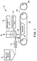
- the apparatus includes a reservoir 12 for supplying a quantity of melted fiber forming thermoplastic polymer resin.
- resins are well known in the art. Examples of such resins which can be used in the practice of the present invention include but are not limited to polypropylene, polyethylene, polyester, polyetherester copolymer, polyurethane, polyether-amide copolymer, and styrene-ethylene, butylene copolymer.
- the properties of such polymers and copolymers may be further enhanced by the addition of various flow modifiers and other additives well known to those skilled in the art.
- polymers are difficult if not impossible to run at high speed throughputs on existing equipment, such as meltblown equipment, due to the high viscosities of the polymers which can cause zippering of the die at increased pressures.
- polymers include PET polyesters, styrene-ethylene, butylene copolymers, and polyetherester copolymers. As demonstrated by the examples below, these polymers can be extruded using the process and apparatus of the present invention.
- the reservoir 12 generally includes means for melting the polymer resin and maintaining the resin in the molten state. Typical resins melt at temperatures in the range of 149 to 260 degrees C. Therefore, the reservoir must be able to maintain resin temperatures to at least within this range.
- a pump 14 pumps the molten resin from the reservoir 12 to one or more fiber forming dies generally indicated at 16.
- the apparatus 10 includes a source of pressurized air 18 for operating an on/off control means discussed below and a source of fiberization fluid 20 to fiberize the molten resin as discussed below. Note that a single die 16 or a multiple die assembly, as in Figures 3 and 4, may be used to form fibers and nonwoven materials according to the present invention.
- the fibers 22 emanating from the die 16 are collected on a receiver assembly such as a continuous wire forming belt 24 in the form of a web 26.
- the receiver assembly can include means 27 for producing a vacuum beneath the receiving portion of the belt 24 to effectively hold the web 26 to the belt surface and affect the density of the resultant nonwoven web 26.
- the receiving surface of the belt 24 is spaced at a predetermined distance A' from the die 16.
- the formed web 26 may be collected on a wind-up roller 28. Alternatively, the web 26 may be further processed downstream from the formation process. Generally, the forming distance A' is between about 7 and 100 centimeters.
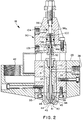
- the fiber forming die 16 in its simplest terms can be viewed as having a main housing 29 for receiving a die assembly including a resin nozzle 31 which is fitted within an air forming chamber 33 and capped with an air plate 35.
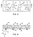
- the air plate 35 may include a plurality of openings for being seated over a plurality of nozzles.
- Figures 3 and 4 show four assemblies 36 in alignment. Alternatively, the assemblies may be aligned in a plurality of rows or staggered to increase the number of openings per unit width.
- the resin nozzle 31 is in turn fitted with a retractable plunger assembly 37 (a part of the on/off control means) which will permit interruption of the resin flow and cleaning of the nozzle orifice.
- the die 16 is adapted to receive supplies of both air and molten resin. The air is separately used to operate the retractable plunger assembly 37 and to draw and attenuate the molten resin into fibers as will be explained in more detail below.
- the molten resin in tracing the flow of the molten resin from entry to exit of the die 16, the molten resin first enters the main housing 29 of the die 16, through the resin inlet port 38 which leads to the interior of the nozzle 31 located within the die 16.
- the nozzle 31 contains a resin chamber or main flow body 39 which houses and surrounds the hydraulically actuated plunger assembly 37. Consequently, the resin inlet port 38 and main flow body 39 are in fluid communication with one another.
- the molten resin As the molten resin enters the main flow body 39 it fills and pressurizes the chamber.
- the molten resin is then released from the chamber through a resin fluid capillary 40 to form fibers via a resin outlet orifice 41 located within the air plate assembly 35.
- the plunger assembly 37 is seated against the base of the resin outlet orifice 41 thereby preventing release of the molten resin.
- the resin is then permitted to escape from the main flow body 39 and thus begin the formation of the fibers 22.
- fiberization/attenuation air or other fluid is used to surround and draw the resin into fibers 22. Consequently, the die means 16 is equipped with primary and, if desired, secondary fiberization means for drawing and attenuating the fibers 22.
- Air or another fluid fiberization source enters the die 16 through a fluid inlet port 42.
- the fluid inlet port 42 is in fluid communication with the air forming chamber 33 which is formed by the space between the interior of the main die housing 29/air plate 35 of the die 16 and the exterior of the nozzle 31.
- the air forming chamber 33 surrounds at least the lower portion of the nozzle 31 and extends into the air plate assembly 35 where it terminates in an annular fluid outlet port 43.
- the fluid outlet port 43 typically has a diameter ranging from 3.0 to 5.0 millimeters. It is this fluid outlet port 43 which forms the primary means for attenuating and fiberizing the fibers 22. As the fluid outlet port 43 is reduced in diameter the fiberization/attenuation air is increased in velocity causing the fibers 22 to be attenuated more severely.
- a secondary fiberization means may also be used.
- the air plate assembly 35 may be fitted with secondary fluid outlet ports 44 spaced radially and axially outward from the first or primary fluid outlet port 43 to create a plurality of secondary fluid streams which impinge upon and further fiberize the molten resin into fibers.
- These secondary fluid outlet ports 44 are in fluid communication with the air supply 20 via fluid channels 45 which connect the secondary fluid outlet ports 44 with the air forming chamber 33.
- the secondary fluid outlet ports 44 may be connected to an independent pressurized fluid source so the type and/or pressure of the fluid emanating therefrom may be controlled independently of the primary fiberization fluid.
- Important to proper fiber and web formation is the balance between the formation of the fibers and their subsequent attenuation.
- the resin outlet orifice 41 and annular fluid outlet port 43 come together directly above an annular wall 46 located in the air plate 35 of the die 16.
- the height of the annular wall 46 is defined by the distance B' between lines 48 and 49. This distance B' is currently limited by machining capabilities; however, the height B' of annular wall 46 is preferably less than 0.5 millimeters. If this height becomes excessively large, molten resin emanating from the resin outlet 41 will collect on the annular wall 46, thus causing large droplets of molten resin to be conveyed onto the formed web 26. These large droplets are called “shot” and may or may not be desirable depending upon the end use of the fibers/nonwoven web.
- the nozzle 31 and thus the resin outlet orifice 41 can be changed relative to the air plate 35 to vary the amount of recess within the die 16.
- This distance C' is measured between the end of the resin outlet orifice 41 (line 50) and the bottom of the annular wall 46 (line 48).
- the recess distance C' is between 0 and 5 millimeters, although the distance depends upon air flow requirements, polymer viscosity and various other factors which in combination result in the effective control and fiberization of the molten resin.
- the end of the nozzle, i.e., the resin outlet orifice 41, and the fluid outlet port 43 lie substantially in the same plane defined by the exterior surface of the air plate portion 35 of the die housing 29. This same plane would also include line 48 shown in Figure 5.
- the air emanating from the fluid outlet port 43 is at a higher velocity causing the resin emanating from the resin outlet orifice 41 to be attenuated more severely.
- the air emanating from the fluid outlet port 43 is at a lower velocity causing the resin emanating from the resin outlet orifice 41 to be attenuated less severely.
- air is fed to the fluid outlet port 43 via the inlet port 42 in the side of the main housing 29 in die 16.
- the inlet port 42 directs the air into the air forming chamber 33 which surrounds the nozzle 31 and which is in communication with the fluid outlet port 43 in the air plate 35.
- the air forming chamber 33 has a cavity surface generally shown at 56.
- the cavity surface 56 has a substantially cylindrical portion 58 having a substantially annular shape when viewed in cross section and a second frustoconical portion 60 located within the air plate 35.
- Surface 60 is inclined at what is termed the primary fluid flow angle defined by angle D' in Figures 4 and 5. This is the angle at which the primary fiberization fluid is directed at the flow of molten resin which is traveling along first axis 61.
- the primary fluid flow angle D' is the angle between the vertical or first axis 61 of the nozzle 31 and a line 51 tangent to the surface of the frustoconical portion 60. Generally, the primary fluid flow angle D' should be between about 15 and 60 degrees. Also note that this first axis 61 defines the initial flow path of the molten resin as it exits the resin outlet orifice 41.
- the air plate assembly 35 may be equipped with secondary fluid outlet ports 44 spaced radially and axially outward from the first or primary fluid outlet port 43 to create a plurality of secondary fluid streams which impinge upon and further fiberize the molten resin into fibers.
- These secondary fluid outlet ports 44 are in fluid communication with the air supply 20 via fluid channels 45 which connect the secondary fluid outlet ports 44 with the air forming chamber 33.
- the secondary fluid outlet ports 44 may be connected to an independent fluid source so the type and/or pressure of the fluid emanating therefrom may be controlled independently of the primary fiberization source.
- the secondary fluid outlet ports 44 may have round or other shaped cross-sections of varying dimensions to produce different fiber forming effects.
- the secondary fluid outlet ports 44 are angled radially inward towards the longitudinal axis 61 of the nozzle 31 so that the secondary fiberization fluid impinges upon the preliminarily formed fibers 22 at a predetermined angle.
- This angle is called the secondary fluid flow angle E' and is measured as the interior angle between the first axis of the resin flow (also the longitudinal axis 61 of nozzle 31) and a line 52 tangent to any one of the fluid streams emanating from the secondary fluid outlet ports 44. See Figure 5.
- This angle E' may be varied between 1 and 45 degrees.
- the concave bottom surface 62 of the air plate 35 in combination with the primary and secondary fiberization fluid flows provides a confined fiberization area wherein the primary fiberization fluid through outlet port 43 contacts and substantially surrounds the flow of resin from resin outlet orifice 41.
- the secondary fiberization fluid impinges upon the preliminarily formed fibers.
- the fiberization air exiting the primary and secondary fluid outlet ports 43 and 44 behaves as a freely expanding jet. A very high level of turbulence is created with this type of jet expansion which causes the molten resin stream to be pulled and drawn in random directions, thereby attenuating and fiberizing the molten resin stream to a very high degree.
- the secondary fiberization streams impinge upon the spread of fibers formed by the primary fiberization fluid flow and at the point of collision of the two flows the fiberization fluid is redirected to produce a non-circular expanding jet as shown by the arrows 63, 64, 65 and 66 in Figure 5.
- This type of turbulent fiberization process is similar to the meltblowing process which is common within the industry. In contrast, however, the process and apparatus of the present invention allows throughputs on a per-hole basis which are as much as 50 times those compared with current meltblown equipment and techniques.
- continuous filament fiberization processes such as spunbonding, the fiberization air is controlled in the laminar region. This causes the molten resin to be attenuated in a controlled environment.
- the advantages of the turbulent fiberization process is that a higher degree of attenuation can be achieved than is possible through the laminar, continuous filament process. This higher degree of attenuation can result in the formation of smaller size fibers.
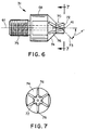
- a first embodiment of the nozzle 31 includes a first axial portion 68 having a first predetermined radial extent and with an axial end portion 70 including a land surface 72, the land surface 72 including the resin outlet orifice 41.
- the axial end portion 70 has a second predetermined radial extent which is less than the first radial extent of the first axial portion 68.
- the nozzle portion 31 further includes a tapered axial portion 74 extending between the first axial portion 68 and the axial end portion 70.
- the angle of the tapered axial portion 74 is defined as the interior angle F' between the longitudinal axis 61 of the nozzle 31 and a line 73 tangent to the surface of the frustoconical portion 74. Generally, this frustoconical angle F' is between about 15 and 60 degrees.
- the nozzle 31 may include a threaded end portion 75 for connecting the nozzle 31 into the main housing 29 of the die 16.
- the nozzle 31 may include further means for directing the flow of the fluid thereabout.
- This fluid flow directing means may comprise a plurality of flutes 76 on the outer surface of the nozzle 31.
- the flutes 76 may extend over the tapered axial portion 74, the axial end portion 70, and into the land surface 72.
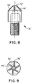
- the nozzle 31' does not include an axial end portion 70. Rather, the land surface 72' is directly adjacent the distal edge of the tapered axial portion 74'. As shown in both the embodiments of Figures 7 and 9, the flutes 76, 76' extend into the land surfaces 72, 72'.
- the fiberization air source 20 provides a primary air flow supply entering into the die through the fluid inlet 42 shown in Figure 2.
- the inner cavity 33 provides a balancing channel for distributing the incoming air about the nozzle 31. The air balances around the nozzle 31 and is then directed towards the fluid outlet port 43 of the air flow channel defined within the cavity 33 due to the air pressure utilized in the system. This primary air flows over the flutes 76, 76' that have been cut into the outside diameter of the nozzle on compound angles thereby causing the fiberization air to spiral about and attenuate the newly-formed fibers 22.
- the flute spiral angle G' around the nozzle tip is the interior angle measured between the first axis 61 of the nozzle 31 and a line 78 parallel to the longitudinal axis of one of the flutes 76, shown as angle G' in Figure 10.
- the flute spiral angle G' should generally be between about 20 and 45 degrees. This spiral angle determines the rotational and centrifugal force of the fluid flow acting on the molten resin stream emitted from the resin outlet orifice 41.
- the flute attack angle H' determines how quickly the air contacts the resin stream. This angle is the angle measured between the longitudinal axis 61 of the nozzle 31 and a line 79 parallel to the interior surface 83 of one of the flutes 76. See Figure 11.
- the attack angle H' in conjunction with the angle of the frustoconical portion 60 of the air forming chamber 33 determines the collision location of the primary air flow as it flows over the flutes 76 and contacts the stream of molten resin which exits the resin outlet orifice 41.
- the flute attack angle H' should generally range between about 7 and 60 degrees.
- the nozzle 31 does not include flutes on the tapered axial portion 74 or on the land surface 72.
- the absence of the flutes in this third embodiment minimizes rotational forces in the air stream. This may be preferred for certain molten polymers which have relatively low melt strength.
- a particularly advantageous feature of the present invention is the interchangeability of the nozzles 31. By removing the air plate 35, the nozzle 31 can be removed and a new nozzle inserted. As a result, changes in resin and fiber formation can be complemented by changes in nozzles.
- the apparatus 10 includes on/off control means for selectively stopping and starting resin flow from the resin outlet orifice 41 while simultaneously dislodging resinous debris therefrom.
- the on/off control means includes a pneumatic fixture generally indicated at 90 which is connected to and therefore forms a part of the main die housing 29. Extending from the pneumatic fixture 90 into the main flow body 39 is a plunger assembly or reciprocating stem 92 having a distal tip 94 located above the resin flow capillary 40.
- the stem 92 has an unseated condition, as shown in Figures 2 and 5, wherein the tip 94 is retracted into the main flow body 39 and spaced from the capillary 40 and a seated condition (not shown) wherein the stem 92 is reciprocated to seat the tip 94 against the capillary 40.
- a hydrostatic pressure is created in the capillary 40 which dislodges any debris located therein and restricts flow of molten resin from the resin flow outlet 41.
- the pneumatic fixture 90 includes a pneumatic chamber 96, including an upper chamber 96a and a lower chamber 96b, shown in Figure 2.
- the stem 92 includes an end portion 98 extending into the pneumatic chamber 96.
- the end portion 98 of the stem 92 has a piston 100 mounted thereon and fitted with seals 102 to contact the walls of chamber 96 to form the upper and lower chambers 96a and 96b, respectively.
- the chamber 96 includes a pair of hydraulic fluid ports 104, 106 opening into the pneumatic chamber 96 for supplying varying fluid pressure on each side of the piston 100 to reciprocate the piston 100 within the pneumatic chamber 96 thereby reciprocating the stem 92 between the seated (off) and unseated (on) conditions.
- the main flow body 39 includes a stem port 108 with the stem 92 extending through the stem port 108.
- the die 16 includes a high temperature resistant dynamic seal 110 for allowing sliding engagement while perfecting a seal between the stem 92 and the stem port 108 to prevent the passage of molten resin through the port 108.
- the seal 110 can be U-shaped in cross-section so as to expand into the space between the stem 92 and the wall of the port 108 upon pressure applied by the incoming polymer resin. Thus, the seal 110 provides a separation between the molten material and the outside environment under molten material pressure conditions.
- the seal mechanism should provide a positive seal at temperatures up to 350 degrees C.
- Operation of the on/off mechanism involves selectively pressurizing either the upper chamber 96a or the lower chamber 96b.
- the pressure from upper chamber 96a is relieved through fluid port 104 and pressurized air is fed into lower chamber 96b via fluid port 106.
- the piston 100 moves further into the upper chamber 96a unseating the tip 94 of the stem 92 from the capillary 40 and thereby allowing the release of the molten resin from the main flow body 39 through resin outlet orifice 41.
- the above procedure is reversed.
- the pressure from the lower chamber 96b is decreased and the pressure in the upper chamber 96a is increased, again causing a pressure imbalance which forces the tip 94 of stem 92 to seat against the capillary 40 and cut off the flow of molten resin. Additionally, this action will create a sufficient hydrostatic pressure within capillary 40 to dislodge any debris located therein.
- the pneumatic fixture 90 may be modified by, as an example, adding a mechanical spring (not shown) within one of the chambers 96a or 96b to further act upon the piston 100 to maintain the stem 92 in either a seated or unseated condition absent the use of air pressure in the opposite chamber.
- the present invention can be utilized under varying conditions to provide a very useful range of throughputs, significantly higher than meltblowing processes.
- the present invention further provides a novel process for forming the nonwoven web 16, generally including the steps of supplying a quantity of melted fiber-forming thermoplastic resin, pumping the resin to the fiber-forming die 16, forming a discrete flow of resin to flow from the die 16, flowing a stream of fiberization fluid, such as air, in contact and substantially surrounding the formed flow or resin, and collecting the formed fibers at a predetermined distance A' from the die 16. More specifically, the flow of fiberization fluid is contained completely about the resin for a predetermined distance, the distance being called the die recess distance C' which is the distance between lines 48 and 50 in Figure 5. This distance can be varied by recessing the outlet orifice from the primary air opening 43.
- the method further includes the step of balancing the fluid flow from the fluid inlet port 42 about the nozzle 31 within the die 16 in the air forming chamber 33.
- the flow of fluid is directed about the nozzle 31 by flowing the fluid over the flutes 76 formed on the exterior of the nozzle 31.
- the spread of the fibers is directed and further fiberized by forming the secondary fiberization fluid flow including at least two fluid streams impinging on the fibers formed by the substantially surrounding primary air flow and colliding the fluid streams to form a non-circular expanding jet as shown in Figure 5 by arrows 63 through 66.
- the secondary fiberization fluid flowing from the two outlet orifices 44 on opposite sides of the surrounding fluid, flows at an angle towards the surrounding fluid flow, defined by angle E' in Figure 5.
- the process further includes the step of selectively stopping the flow of resin from the resin outlet orifice 41.
- the stem 92 is reciprocated so that the distal tip 94 of the stem 92 seats against the surface of the resin outlet capillary 40 to stop the resin flow and unseats the distal tip 94 from the resin outlet capillary 40 to unstop the resin flow.
- the seating of the distal tip 94 creates a hydrostatic pressure in the capillary 40 to dislodge debris from the capillary 40 and the resin outlet orifice 41.
- the stem 92 reciprocates by pneumatic actuation of the piston 100 connected to the stem 92 disposed within the pneumatic chamber 96 to seat and unseat the distal tip 94.
- the stem 92 can be reciprocated with short or long strokes.
- the resin outlet orifice 41 has a preferred diameter of between 0.5 and 1.0 millimeters, although trials have shown effective fiberization utilizing a polymer orifice diameter of up to 3 millimeters.
- the nozzle recess C' has been varied between 0 and 5 millimeters with resulting effective fiberization.
- the nozzle temperature has been varied between 138 and 330 degrees C. Tests have shown an effective air flow of 56 to 1558 standard liters per minute per nozzle with resulting effective fiberization.
- Nozzle air pressure has been varied between 6.9 and 172 kPa with some trials utilizing pressures as high as 317 kPa.
- Fiberization air temperatures have been varied between 137 and 343 degrees C depending on the polymer utilized.
- a forming distance A' between the nozzle tip and the landing area of the receiving belt has been varied between 15 and 64 centimeters although some trials have been successful utilizing a distance as low as 7.5 centimeters or as high as 102 centimeters.
- Polymer throughput has been varied between 0.76 and 38 grams per minute per nozzle although other trials have achieved throughputs up to 151 grams per minute per nozzle and as low as 0.1 grams per minute per nozzle.
- Polymers which can be fiberized with the present invention include, but are not limited to, polypropylene, polyethylene, polybutylene, PET polyester, PETG copolyester, PBT polyester, ethylene vinyl acetate copolymer, polyurethane, polyetherester copolymers, and styrene/ethylene-butylene copolymers.
- both the nozzle tip geometry and the air plate geometry can be varied to change the characteristics of the resultant fiber formation.
- both the nozzle recess distance and the forming distance between the die and the receiver can be varied to affect the fiber formation and the attributes of the resultant nonwoven web.
- a PET polyester manufactured by Eastman Chemical Products, Inc. and designated No. 9028 was extruded at a melt temperature of 287 degrees C at a throughput of 3.1 grams per hole per minute resulting in a melt pressure of 455 kPa.
- the fiberization fluid was air at a flow rate of 177 standard liters per minute per nozzle with an air temperature of 293 degrees C.
- the nozzles located within the die housing had a first axial portion diameter of 12 millimeters, a cylindrical end portion diameter of 5 millimeters, a resin outlet orifice diameter of 1 millimeter with the angle of the frustoconical section being 45 degrees.
- the nozzles included six flutes having a flute spiral angle of 20 degrees and a flute attack angle of 7 degrees.
- Air flow geometry included a primary air opening diameter of 5 millimeters, a primary fluid flow angle of 45 degrees and two secondary air orifices both having a 1.5 millimeter diameter with a 180 degree separation.
- the secondary fluid flow angle was 45 degrees.
- the nozzle recess distance was 2 millimeters and the forming distance between the die and the receiver was 38.10 centimeters.
- the average fiber diameter was 15.5 ⁇ m the web formed from the extruded fibers had a density of approximately 0.061 grams per cubic centimeter and the average shot size using an optical microscope was 0.015 square millimeters.
- a PETG copolyester manufactured by Eastman Chemical Products, Inc. and designated Kodar 6763 was extruded at a melt temperature of 287 degrees C at a throughput of 7.4 grams per hole per minute, resulting in a melt pressure of 896 kPa.
- the fiberization fluid was air at a flow rate of 127 standard liters per minute per nozzle with an air temperature of 283 degrees C.
- the nozzles located within the die housing had a first axial portion diameter of 12 millimeters, a cylindrical end portion diameter of 5 millimeters, a resin outlet orifice diameter of 1 millimeter with the angle of the frustoconical section being 45 degrees.
- the nozzles included six flutes having a flute spiral angle of 20 degrees and a flute attack angle of 7 degrees.
- Air flow geometry included a primary air opening diameter of 5 millimeters, a primary fluid flow angle of 45 degrees and two secondary air orifices both having a 2.0 millimeter diameter with a 180 degree separation.
- the secondary fluid flow angle was 45 degrees.
- the nozzle recess distance was 2 millimeters and the forming distance between the die and the receiver was 58 centimeters. Under the above conditions, the average fiber diameter was 24.9 ⁇ m the web formed from the extruded fibers had a density of approximately 0.050 grams per cubic centimeter and the average shot size using an optical microscope was 0.0076 square millimeters.
- Polyurethane manufactured by B. F. Goodrich and designated Estane 5740x732 was extruded at a melt temperature of 216 degrees C at a throughput of 6.6 grams per hole per minute resulting in a melt pressure of 827 kPa.
- the fiberization fluid was air at a flow rate of 184 standard liters per minute per nozzle with an air temperature of 232 degrees C.
- the nozzles located within the die housing had a first axial portion diameter of 12 millimeters, a cylindrical end portion diameter of 5 millimeters, a resin outlet orifice diameter of 1 millimeter with the angle of the frustoconical section being 45 degrees.
- the nozzles included six flutes having a flute spiral angle of 20 degrees and a flute attack angle of 7 degrees.
- Air flow geometry included a primary air opening diameter of 5 millimeters, a primary fluid flow angle of 45 degrees and two secondary air orifices both having a 1.5 millimeter diameter with a 180 degree separation.
- the secondary fluid flow angle was 25 degrees.
- the nozzle recess distance was 2 millimeters and the forming distance between the die and the receiver was 15 centimeters.
- the average fiber diameter was 24 ⁇ m the web formed from the extruded fibers had a density of approximately 0.150 gm/cm3 and the average shot size using an optical microscope was 0.0098 square millimeters.
- a styrene-ethylene-butylene-styrene copolymer manufactured by The Shell Chemical Company and designated Kraton G-2740X was extruded at a melt temperature of 238 degrees C at a throughput of 3.7 grams per hole per minute resulting in a melt pressure of 586 kPa.
- the fiberization fluid was air at a flow rate of 120 standard liters per minute per nozzle with an air temperature of 263 degrees C.
- the nozzles located within the die housing had a first axial portion diameter of 12 millimeters, a cylindrical end portion diameter of 4 millimeters, a resin outlet orifice diameter of 1 millimeter with the angle of the frustoconlcal section being 45 degrees.
- the nozzles included six flutes having a flute spiral angle of 20 degrees and a flute attack angle of 45 degrees.
- Air flow geometry included a primary air opening diameter of 4 millimeters, a primary fluid flow angle of 45 degrees and air openings, all having a 1.5 millimeter diameter.
- the secondary fluid flow angles were each 45 degrees.
- the nozzle recess distance was 2 millimeters and the forming distance between the die and the receiver was 23 centimeters. Under the above conditions, the average fiber diameter was 86 ⁇ m, the web formed from the extruded fibers had a density of approximately 0.161 gm/cm3 and the average shot size using an optical microscope was 0.025 square millimeters.
- a polymer containing by weight 83% Dow Chemical Aspun 6814 polyethylene, 12% Allied Chemical AC-9 polyethylene, 4% blue polyethylene coloring and 1% wetting agent was extruded at a melt temperature of 232 degrees C at a throughput of 18.9 grams per hole per minute using a melt pressure of 2758 kPa.
- the fiberization fluid was air at a flow rate of 348 standard liters per minute per nozzle with an air temperature of 210 degrees C.
- the nozzles located within the die housing had a first axial portion diameter of 12 millimeters, a cylindrical end portion diameter of 5 millimeters, a polymer exit orifice diameter of 1 millimeter with the angle of the frustoconical section being 45 degrees.
- the nozzles included six flutes having a flute spiral angle of 20 degrees and a flute attack angle of 7 degrees.
- Air flow geometry included a primary air opening diameter of 5 millimeters, a primary fluid flow angle of 45 degrees and two secondary air orifices with 180 degrees separation, both having a 2 millimeter diameter.
- the secondary fluid flow angle was 45 degrees.
- the nozzle recess distance was 4 millimeters and the forming distance between the die and the receiver was 54 centimeters. Under the above conditions, the average fiber diameter was 21 ⁇ m, the web formed from the extruded fibers had a density of approximately 0.072 gm/cm3 and the average shot size using an optical microscope was 0.24 square millimeters.
- a blend of 93.5% Himont Profax PF-015 polypropylene, 4.0% Standridge Color Corp. 5834 blue polypropylene color concentrate and 2.5% wetting agent was extruded at a melt temperature of 235 degrees C at a throughput of 18.9 grams per hole per minute resulting in a melt pressure of 1172 kPa.
- the fiberization fluid was air at a flow rate of 266 standard liters per minute per nozzle with an air temperature of 235 degrees C.
- the nozzles located within the die housing had a first axial portion diameter of 12 millimeters, a cylindrical end portion diameter of 5 millimeters, a resin outlet orifice diameter of 1 millimeter with the angle of the frustoconical section being 45 degrees.
- the nozzles included six flutes having a flute spiral angle of 20 degrees and a flute attack angle of 7 degrees.
- Air flow geometry included a primary air opening diameter of 4 millimeters, a primary fluid flow angle of 45 degrees and two 1.5 millimeter diameter secondary air orifices on each side of the primary air openings. The secondary fluid flow angle was 45 degrees.
- the nozzle recess distance was 2 millimeters and the forming distance between the die and the receiver was 48 centimeters. Under the above conditions, the average fiber diameter was 21 ⁇ m, the web formed from the extruded fibers had a density of approximately .080 gm/cm3 and the average shot size using an optical microscope was 0.11 square millimeters.
- Profax PF-015 polypropylene was extruded at a melt temperature of 260 degrees C at a throughput of 2.8 grams per hole per minute resulting in a melt pressure of 103 kPa.
- the fiberization fluid was air at a flow rate of 545 standard liters per minute per nozzle with an air temperature of 260 degrees C.
- the nozzles located within the die housing had a first axial portion diameter of 12 millimeters, a cylindrical end portion diameter of 1.25 millimeters and a resin outlet orifice diameter of 1 millimeter with the angle of the frustoconical section being 30 degrees.
- the nozzles had no flutes.
- Air flow geometry included a primary air opening diameter of 3 millimeters, a primary fluid flow angle of 30 degrees and three secondary air orifices on each side of the air plate, all having a 1.5 millimeter diameter.
- the secondary fluid flow angle was 45 degrees.
- the nozzle recess distance was 0.5 millimeters and the forming distance between the die and the receiver was 48 centimeters.
- the average fiber diameter was 2.3 ⁇ m the web formed from the extruded fibers had a density of approximately 0.069 gm/cm3 and the average shot size using an optical microscope was 0.034 square millimeters.
- Himont Profax PF-015 polypropylene was extruded at a melt temperature of 260 degrees C at a throughput of 148 grams per hole per minute resulting in a melt pressure of 1710 kPa.
- the fiberization fluid was air at a flow rate of 1558 standard liters per minute per nozzle with an air temperature of 260 degrees C.
- the nozzle located within the die housing had a first axial portion diameter of 12 millimeters, a cylindrical end portion diameter of 5 millimeters, a resin outlet orifice diameter of 1 millimeter with the angle of the frustoconical section being 45 degrees.
- the nozzle included six flutes having a flute spiral angle of 20 degrees and a flute attack angle of 7 degrees.
- Air flow geometry included a primary air opening diameter of 5 millimeters, a primary fluid flow angle of 45 degrees and two secondary air orifices both having a 1.5 millimeter diameter with a 180 degree separation.
- the secondary fluid flow angle was 45 degrees.
- the nozzle recess distance was 2 millimeters and the forming distance between the die and the receiver was 38 centimeters.
- the average fiber diameter was 30 ⁇ m the web formed from the extruded fibers had a density of approximately 0.069 gm/cm3 and the average shot size using an optical microscope was 0.30 square millimeters.
- Himont Profax PF-015 polypropylene was extruded at a melt temperature of 260 degrees C at a throughput of 37 grams per hole per minute using a melt pressure of 690 kPa.
- the fiberization fluid was air at a flow rate of 651 standard liters per minute per nozzle with an air temperature of 260 degrees C.
- the nozzles located within the die housing had a first axial portion diameter of 12 millimeters, a cylindrical end portion diameter of 5 millimeters, a polymer exit orifice diameter of 1 millimeter with the angle of the frustoconical section being 45 degrees.
- the nozzles included six flutes having a flute spiral angle of 20 degrees and a flute attack angle of 7 degrees.
- Air flow geometry included a primary air opening diameter of 5 millimeters, a primary fluid flow angle of 45 degrees and two secondary air orifices both having a 1.5 millimeter diameter with a 180 degree separation.
- the secondary fluid flow angle was 45 degrees.
- the nozzle recess distance was 2 millimeters and the forming distance between the die and the receiver was 38 centimeters.
- the average fiber diameter was 3.1 ⁇ m the web formed from the extruded fibers had a density of approximately 0.049 gm/cm3 and the average shot size using an optical microscope was 0.078 square millimeters.
- Arnitel EM-450 polyetherester copolymer manufactured by Akzo was extruded at a melt temperature of 266 degrees C at a throughput of 2.95 grams per hole per minute resulting in a melt pressure of 869 kPa.
- the fiberization fluid was air at a flow rate of 404 standard liters per minute per nozzle with an air temperature of 264 degrees C.
- the nozzles located within the die housing had a first axial portion diameter of 12 millimeters, a cylindrical end portion diameter of 5 millimeters, a resin outlet orifice diameter of 1 millimeter with the angle of the frustoconical section being 45 degrees.
- the nozzles included six flutes having a flute spiral angle of 20 degrees and a flute attack angle of 7 degrees.
- Air flow geometry included a primary air opening diameter of 5 millimeters, a primary fluid flow angle of 45 degrees and two secondary air orifices both having a 1.5 millimeter diameter with a 180 degree separation.
- the secondary fluid flow angle was 25 degrees.
- the nozzle recess distance was 2 millimeters and the forming distance between the die and the receiver was 24 centimeters.
- the average fiber diameter was 12 ⁇ m
- the web formed from the extruded fibers had a density of approximately 0.104 gm/cm3 and the average shot size using an optical microscope was 0.058 square millimeters.
- Himont Profax PF-015 polypropylene was extruded at a melt temperature of 260 degrees C at a throughput of 23 grams per hole per minute resulting in a melt pressure of 1931 kPa.
- the drawing air was at an air flow rate of 375 standard liters per minute per nozzle with an air temperature of 274 degrees C.
- the nozzles located within the die housing had a first axial portion diameter of 12 millimeters, a cylindrical end portion diameter of 4 millimeters, a resin outlet orifice diameter of 0.5 millimeters with the angle of the frustoconical section being 45 degrees.
- the nozzles included six flutes having a flute spiral angle of 20 degrees and a flute attack angle of 7 degrees.
- Air flow geometry included a primary air opening diameter of 5 millimeters, a primary fluid flow angle of 45 degrees and two secondary air orifices each having a 2 millimeters diameter with a 180 degree separation.
- the secondary fluid flow angle was 45 degrees.
- the nozzle recess distance was 2 millimeters and the forming distance between the die and the receiver was 13 centimeters.
- the average fiber diameter was 5.7 ⁇ m the web formed from the extruded fibers had a density of approximately 0.035 gm/cm2 and the average shot size using an optical microscope was 0.079 square millimeters.
- Profax PF-015 polypropylene was extruded at a melt temperature of 260 degrees C at a throughput of 0.34 grams per hole per minute resulting in a melt pressure of 69 kPa.
- the fiberization fluid was air at a flow rate of 136 standard liters per minute per nozzle with an air temperature of 304 degrees C.
- the nozzles located within the die housing had a first axial portion diameter of 12 millimeters, a cylindrical end portion diameter of 1.25 millimeters, a resin outlet orifice diameter of 1 millimeter with the angle of the frustoconical section being 30 degrees.
- the nozzles had no flutes.
- Air flow geometry included a primary air opening diameter of 4 millimeters, a primary fluid flow angle of 45 degrees and three secondary air orifices on each side of each resin outlet orifice, all having a 1.5 millimeter diameter.
- the secondary fluid flow angle was 45 degrees.
- the nozzle recess distance was 2 millimeters and the forming distance between the die and the receiver was 39 centimeters.
- the average fiber diameter was less than 2.0
- the web formed from the extruded fibers had a density of approximately 0.039 gm/cm3 and the average shot size using an optical microscope was 0.020 square millimeters.
- Himont Profax PF-015 polypropylene was extruded at a melt temperature of 260 degrees C at a throughput of 38.4 grams per hole per minute resulting in a melt pressure of 462 kPa.
- the fiberization fluid was air at a flow rate of 1104 standard liters per minute per nozzle with an air temperature of 260 degrees C.
- the nozzle located within the die housing had a first axial portion diameter of 12 millimeters, a cylindrical end portion diameter of 5 millimeters, a resin outlet orifice diameter of 2 millimeters with the angle of the frustoconical section being 45 degrees.
- the nozzle included six flutes having a flute spiral angle of 20 degrees and a flute attack angle of 7 degrees.
- Air flow geometry included a primary air opening diameter of 5 millimeters, a primary fluid flow angle of 45 degrees and two secondary air orifices both having a 1.5 millimeter diameter with a 180 degree separation.
- the secondary fluid flow angle was 45 degrees.
- the nozzle recess distance was 2 millimeters and the forming distance between the die and the receiver was 38 centimeters.
- the average fiber diameter was 3.3 ⁇ m the web formed from the extruded fibers had a density of approximately 0.095 gm/cm3 and the average shot size using an optical microscope was 0.14 square millimeters.
- Himont Profax PF-015 polypropylene was extruded at a melt temperature of 260 degrees C at a throughput of 38.3 grams per hole per minute resulting in a melt pressure of 283 kPa.
- the fiberization fluid was air at a flow rate of 651 standard liters per minute per nozzle with an air temperature of 260 degrees C.
- the nozzle located within the die housing had a first axial portion diameter of 12 millimeters, a cylindrical end portion diameter of 5 millimeters, a resin outlet orifice diameter of 3 millimeters with the angle of the frustoconical section being 45 degrees.
- the nozzle included six flutes having a flute spiral angle of 20 degrees and a flute attack angle of 7 degrees.
- Air flow geometry included a primary air opening diameter of 5 millimeters, a primary fluid flow angle of 45 degrees and two secondary air orifices both having a 1.5 millimeter diameter with a 180 degree separation.
- the secondary fluid flow angle was 45 degrees.
- the nozzle recess distance was 2 millimeters and the forming distance between the die and the receiver was 38 centimeters.
- the average fiber diameter was 3.1 the web formed from the extruded fibers had a density of approximately 0.065 gm/cm3 and the average shot size using an optical microscope was 0.075 square millimeters.
- the process and apparatus of the present invention permit the formation of fibers and resultant nonwoven webs from a wide variety of polymers under various conditions.
- Typical meltblown equipment under the very best of conditions can only process standard polymers at rates of no more than 3 grams per hole per minute. With certain polymers, even these throughputs are not possible due to the danger of the meltblown dies zippering.
- the process and the apparatus of the present invention has been shown to be able to process polymers at rates as high as 150 grams per hole per minute. In port, this higher throughput capability is due to the higher melt pressure capability of the nozzle. As spelled out in the working examples, melt pressures up to 2758 kPa can be withstood.
- melt pressures as high as 6900 kPa can be withstood without failure of equipment. This is in contrast to meltblown die tip pressures which are believed to have maximum let pressures of only 2100 kPa.
- the present apparatus may be used in single or multiple die configurations which, on a per hole basis, will far exceed current meltblown capabilities.
- the apparatus of the present invention may be used in areas where space constraints are critical.
- the apparatus may be used to create localized fiber formation thereby permitting the creation of the nonwoven webs having wide variances in their basis weights. Nonwoven webs with variances in their basis weights in excess of 10% have been created by localized increases and/or reductions in fiber formations in either or both of the machine and cross-directions. Consequently, it can be seen that the process and apparatus of the present invention can be applied in a wide variety of applications to enhance current nonwoven forming techniques.
- a process of claim 12 which further includes the step of fiberizing said resin flows to form fibers by flowing a primary fiberization fluid in completely surrounding contact with each said flow of resin, said primary fiberization fluid contacting each said resin flow at a primary fluid flow angle of between about 15 and 60 degrees, said angle being measured as an interior angle between the intersection of the first axis of each said flows of resin and a line tangent to the flow of said primary fiberization fluid about said individual flows of resin.
- the process includes the step of further fiberizing said resin flows prior to collecting said fibers by contacting said individual resin flows with a flow of a secondary fiberization fluid including at least two fluid streams which each impinge upon said resin flows at a secondary fluid flow angle of between about 1 and 45 degrees, said angle being measured as an interior angle between the intersection of the first axis of each of said flows of resin and a line tangent to the flow of said secondary fiberization fluid flows about said individual flows of resin.
- the process includes the step of angling at least one of said primary fiberization fluid flows such that it spirals about said first axis of said flow of resin.
- the process comprises the step of collecting said fibers in the form of a nonwoven web.
- the apparatus according to the invention for intermittently forming fibers from a fiber forming resin comprises: a die housing; a die assembly located within said housing including a resin chamber for receiving a supply of molten fiber forming resin, said chamber having a resin outlet orifice in fluid communication therewith for emitting said molten resin in the form of a flow, said flow defining a first axis; fiberization means for drawing said flow of molten resin into fibers; and on/off control means for selectively interrupting flow of said molten resin from said resin outlet orifice.
- the apparatus with fiberization means includes a primary fiberization fluid which completely surrounds said flow of molten resin.
- the apparatus with a die housing includes a fluid outlet port completely surrounding said resin outlet orifice for emitting said primary fiberization fluid.
- the apparatus with on/off control means includes a plunger within said resin chamber having a closed position wherein said plunger is in contact with said resin outlet orifice to prevent flow of said molten resin from said orifice and an open position wherein said plunger is retracted from said orifice to allow flow of said molten resin from said orifice.
- the apparatus with a die housing includes a hydraulic chamber said plunger including an end portion extending into said hydraulic chamber and including a piston mounted thereon, said chamber including hydraulic fluid ports opening into said hydraulic chamber for supplying varying fluid pressure on each side of said piston to reciprocate said piston within said hydraulic chamber to move said plunger between said open and closed positions.
- the apparatus with fiberization means includes a fluid outlet port in said die housing completely surrounding said flow of resin from said resin outlet orifice and a primary fiberization fluid emanating from said fluid outlet port for fiberizing said resin to form fibers, said primary fiberization fluid contacting said flow of resin at a primary fluid flow angle of between about 15 and 60 degrees, said angle being measured as an interior angle between the intersection of the first axis of said flow of resin and a line tangent to the flow of said primary fiberization fluid.
- the apparatus with fiberization means further includes a secondary fiberization fluid including at least two fluid streams which each impinge upon said flow of resin at a secondary fluid flow angle of between about 1 and 45 degrees, said angle being measured as an interior angle between the intersection of the first axis of said flow of resin and a line tangent to the flow of said fluid stream.
- the apparatus with a die housing further includes a nozzle located therein and at least partially surrounded by a fiberization fluid chamber which terminates in said fluid outlet port, said nozzle including said resin chamber and said resin outlet orifice.
- the nozzle is removably retained within said die housing.
- the apparatus with the nozzle has a nozzle exterior surface, said nozzle exterior surface having a plurality of flutes adjacent said resin outlet orifice to direct said primary fiberization fluid.
- the apparatus with the nozzle exterior surface includes a first axial portion having a first predetermined radial extent and an axial end portion having preferably a substantial cylindrical outer surface having a land surface including said resin outlet orifice extending therethrough and having a second predetermined radial extent which is less than said first radial extent, said nozzle including a tapered axial portion extending between said first axial portion and said axial end portion including said plurality of flutes, said flutes extending into said land surface and preferably are situated in the cylindrical outer surface.
- the nozzle has a flute attack angle of about 7 to 60 degrees and a flute spiral angle of about 20 to 45 degrees.
- the nozzle has a frustoconical angle of about 15 to 60 degrees.
Abstract
Description
- The present invention relates to a process and an apparatus for forming fibers.
- The manufacture of nonwoven fabrics is a highly developed art. Generally, nonwoven webs or mats are made by forming filaments or fibers of varying or specific diameter and depositing them on a carrier in such a manner so as to cause the filaments or fibers to overlap or entangle as a web of a desired basis weight.
- Various means have been developed in an attempt to control the form of the processed fibers which in turn affects the properties of the formed web. For example, U.S. Patent 2,571,457 to Ladisch, issued October 16, 1951 discloses a spray nozzle for forming filaments and/or fibers in diameters of about one micron and smaller by passing a polymer stream through the central orifice of a nozzle with an elastic fluid such as air being caused to spiral towards the vertex of a cone. U.S. Patent 3,017,664 to Ladisch, issued January 23, 1962 discloses a fiber forming nozzle wherein a stream of polymer material exits a nozzle orifice in the form of a tube, formation of the tube being caused by the spreading of the polymer over the outside wall of a circular body positioned in the orifice. An elastic fluid rotating in a spiraling manner around the film of polymer with a very high velocity creates a vacuum between the film and elastic fluid. Fibers are picked up from the film of fiber forming liquid and drawn out to fineness in the elastic fluid. Although both Ladisch patents disclose a spiraling air which surrounds the resin flow from an orifice, the emitted air is transmitted through nozzle openings which do not surround the polymer stream.
- U. S. Patent 3,543,332 to Wagner et al, issued December 1, 1970, discloses the production of fibers utilizing a spinning nozzle, the spinning nozzle having a central orifice for forming a polymer stream and additional orifices surrounding the central orifice for the passage of fiber forming air.
- U. S. Patent 3,755,527 to Keller et al, issued August 28, 1973, discloses a process for producing meltblown nonwoven synthetic polymer mats. The meltblown process utilizes a plurality of extrusion orifices through which a melted polymer resin is extruded. On each side of the plurality of orifices is a hot air slot for supplying a stream of hot gas in the form of a sheet on each side of the plurality of fiber streams formed from the resin. To produce fibers having diameters between 10 and 40 µm combinations of die tip temperature, resin flow rate, and resin molecular weight are selected to give an apparent viscosity in the die holes from about 10 to 800 poise.* The viscosity is then adjusted into an operable range by varying the die tip temperature.
*1 poise = 100 mPa.s - U. S. Patent 3,905,734 to Blair, issued September 16, 1975 discloses improvements for an apparatus for continuous tube forming by meltblowing techniques. The assembly utilizes knife-like streams of forming gas on each sideof a polymer exit orifice.
- U.S. Patent No. 3,978,185 to Buntin et al, issued August 31, 1976 discloses a meltblown nonwoven mat prepared from thermoplastic polymer fibers which are alleged to be substantially completely free of polymer shot and produced at a high polymer throughput rate in a specific meltblowing process in which thermoplastic polymer resins having a specific viscosity range are degraded in the presence of a free radical source compound.
- U.S. Patent Nos. to Oshido et al, 4,135,903 issued January 23, 1979 and 4,185,981 issued January 29, 1980 disclose a method and apparatus for producing fibers from a heat softening material utilizing high speed gas streams which cause the melted polymer to rotate around its central axis line and transform it into a substantially conical shape whose cross-section gradually decreases towards its flowing direction in a first cone and is caused to advance in the form of fiber from the tip of the cone in the flowing direction and outwardly in the radial direction in a second cone.
- It remains desirable to develop further method and apparatus for forming fibers from molten fiber forming resins suitable for then forming mats from the formed fibers wherein the apparatus and process provide increased throughput on a per-hole basis and wider operating ranges.
- This object is solved by the process of
independent claims 1 and 12 and the apparatus and use of the apparatus according toindependent claims - The invention provides means for manufacturing nonwoven fabrics useful for a wide variety of applications, such as for personal care products, household cleaning materials and wipers, and the like. More specifically, the present invention provides a novel method and means for forming fibers from a fiber forming thermoplastic polymer resin suitable for forming a nonwoven web.
- Apparatus and processes described in the above references are quite capable of forming flat mats or webs of nonwoven material which are most commonly subjected to additional processing for incorporation into other products such as diapers and other personal care items or subsequent conversion into such items as disposable workwear. With the advancement of nonwoven fiber forming technology, however, the uses and applications for such materials have been greatly enhanced and as new uses and applications are found, the design limitations of current equipment become more evident. Further, with the increasing costs of the polymers used in the formation of fibers, overall production costs become an ever important factor. The invention provides one way to reduce the cost of the nonwoven material by allowing to increase the production capability of the equipment, while with current meltblowing equipment, there are severe limitations as to the amount of polymer throughput which can be tolerated by the meltblowing dies. (As polymer viscosities and pressures increase, so does the likelihood of the dies, themselves, fracturing or "zippering" as it is known in the industry.)
- The present invention, therefore provides an apparatus and process which allow for substantially higher polymer pressures and thus higher throughputs on a per-hole basis relative to normal meltblown die tip construction.
- Another major problem in the previous formation of nonwoven fibers and the resultant webs is a phenomenon called "shot". Shot occurs when drawing air is improperly applied to the extruded polymer stream. When this condition occurs, small beads of polymer are formed along with the fibers, thereby giving the formed web a very rough feel. This can be caused by equipment design, improper adjustment of the air to polymer ratio, processing conditions, or a combination of the three. In almost all applications, shot is not desirable.
- The present invention, however, provides a process and apparatus with increased air flow to and around the extruded polymer, when desired, to decrease shot, and increase fiber formation efficiency or reverse the process when necessary.
- As the demands upon nonwoven materials become more complex, it is sometimes desirable to form nonwoven materials which are comprised of intimately entangled fibers of different polymer composition and/or fiber size. The actual generation of materials using more than one polymer and/or fiber typically requires production in a multi-bank layered setup wherein one bank of dies forms fibers of one size or polymer, while another set of dies produces fibers of another size or polymer.
- The present invention, therefore, provides an apparatus and process which will permit the formation of multi-component nonwoven materials in a more localized and efficient manner.
- Another drawback with current meltblowing apparatus and processes are their inability to produce nonwoven materials which are three-dimensional in structure and/or zoned in density in either or both the machine and cross directions. A primary reason for this is the fact that the meltblowing equipment as described in the above references is planar in design and must operate on a continuous basis due to the heating requirements of the polymer and the problem with die holes plugging with stagnant polymer. Consequently, such equipment cannot be cycled on and off to create nonwoven materials having varying densities and other attributes.
- The present invention, therefore, provides an apparatus and process which allow cyclical release of polymer during the fiber forming process.
- With current meltblowing equipment, described in the above references, production runs are made at a specified width which usually corresponds to the width of the bank of meltblown die tips or openings.
- To change widths, holes must be plugged or the system shut down to refit the line with smaller or larger banks of die tips. The present invention, therefore provides an apparatus and process which allow on-line variations in production widths of the nonwoven material. Lastly, current meltblowing equipment often becomes clogged when the small die openings become filled with solidified polymer. Usually, there is very little that can be done to unclog the holes while the machinery is running. While a few clogged holes will usually not affect production quality, once enough of the holes become clogged, the die tip must be taken off-line and cleaned - -a costly and time-consuming process.
- The present invention therefore also provides a process and apparatus which is self-cleaning.
- These and other features and advantages of the present invention will become more apparent upon a further review of the following specification and drawings.
- In accordance with the present invention there is provided a process and apparatus of the type for forming a nonwoven web from a fiber forming thermoplastic polymer resin, the apparatus including reservoir means for supplying a quantity of melted fiber forming thermoplastic polymer resin and pump means for pumping the resin from the reservoir means to a fiber forming die. Die means forms a discrete flow of resin which is pumped from the reservoir means. The die means includes fiberization means for forming fibers from the flow of resin utilizing first fluid passage means for forming a stream of fluid, such as air, which contacts and substantially surrounds the formed flow of resin for a predetermined distance within the die means. The fiberization means may further include a second fluid passage means for further contacting and attenuating the formed fibers. Receiver means spaced at an adjustable predetermined distance from the die means collects the fibers formed from the fluid passage means, thereby forming the nonwoven web. A hydraulically actuated stem within the die means provides an on/off control for selectively stopping flow of the fiber forming resin. The stem may be further used to dislodge resinous debris from the die means.
- Other advantages of the present invention will be readily appreciated as the same becomes better understood by reference to the following detailed description when considered in connection with the accompanying drawings wherein:
- Figure 1 is a schematic illustration of an apparatus constructed in accordance with the present invention;
- Figure 2 is a cross-sectional view of the die constructed in accordance with the present invention;
- Figure 3 is a top plan view of a die plate constructed in accordance with the present invention;
- Figure 4 is a cross-sectional view taken substantially along lines 4-4 of Figure 3;
- Figure 5 is an enlarged fragmentary cross-sectional view of the nozzle within the die assembly;
- Figure 6 is a side view of a nozzle constructed in accordance with the present invention;
- Figure 7 is a plan view taken substantially along lines 7-7 of Figure 6;
- Figure 8 is a side view of another nozzle constructed in accordance with the present invention;
- Figure 9 is an end view of the nozzle shown in Figure 8;
- Figure 10 is another side view of the nozzle of Figure 6 showing the flute spiral angle G'.
- Figure 11 is a perspective view of the nozzle of Figure 6 showing the flute attack angle H';
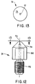
- Figure 12 is a side view of yet another embodiment of a nozzle constructed in accordance with the present invention.
- Figure 13 is a plan view taken substantially along lines 13-13 of Figure 12.
- An apparatus of the type for forming a nonwoven web from a fiber forming thermoplastic polymer resin is shown schematically at 10 in Figure 1. Generally, the apparatus includes a
reservoir 12 for supplying a quantity of melted fiber forming thermoplastic polymer resin. Such resins are well known in the art. Examples of such resins which can be used in the practice of the present invention include but are not limited to polypropylene, polyethylene, polyester, polyetherester copolymer, polyurethane, polyether-amide copolymer, and styrene-ethylene, butylene copolymer. Furthermore, the properties of such polymers and copolymers may be further enhanced by the addition of various flow modifiers and other additives well known to those skilled in the art. - Many of these polymers are difficult if not impossible to run at high speed throughputs on existing equipment, such as meltblown equipment, due to the high viscosities of the polymers which can cause zippering of the die at increased pressures. Examples of such polymers include PET polyesters, styrene-ethylene, butylene copolymers, and polyetherester copolymers. As demonstrated by the examples below, these polymers can be extruded using the process and apparatus of the present invention.
- The
reservoir 12 generally includes means for melting the polymer resin and maintaining the resin in the molten state. Typical resins melt at temperatures in the range of 149 to 260 degrees C. Therefore, the reservoir must be able to maintain resin temperatures to at least within this range. Apump 14 pumps the molten resin from thereservoir 12 to one or more fiber forming dies generally indicated at 16. Theapparatus 10 includes a source ofpressurized air 18 for operating an on/off control means discussed below and a source offiberization fluid 20 to fiberize the molten resin as discussed below. Note that asingle die 16 or a multiple die assembly, as in Figures 3 and 4, may be used to form fibers and nonwoven materials according to the present invention. - The
fibers 22 emanating from the die 16 are collected on a receiver assembly such as a continuouswire forming belt 24 in the form of aweb 26. The receiver assembly can include means 27 for producing a vacuum beneath the receiving portion of thebelt 24 to effectively hold theweb 26 to the belt surface and affect the density of the resultantnonwoven web 26. The receiving surface of thebelt 24 is spaced at a predetermined distance A' from thedie 16. The formedweb 26 may be collected on a wind-uproller 28. Alternatively, theweb 26 may be further processed downstream from the formation process. Generally, the forming distance A' is between about 7 and 100 centimeters. - Referring to Figure 2, the
fiber forming die 16 in its simplest terms can be viewed as having amain housing 29 for receiving a die assembly including aresin nozzle 31 which is fitted within anair forming chamber 33 and capped with anair plate 35. Theair plate 35 may include a plurality of openings for being seated over a plurality of nozzles. Figures 3 and 4 show fourassemblies 36 in alignment. Alternatively, the assemblies may be aligned in a plurality of rows or staggered to increase the number of openings per unit width. Theresin nozzle 31 is in turn fitted with a retractable plunger assembly 37 (a part of the on/off control means) which will permit interruption of the resin flow and cleaning of the nozzle orifice. Thedie 16 is adapted to receive supplies of both air and molten resin. The air is separately used to operate theretractable plunger assembly 37 and to draw and attenuate the molten resin into fibers as will be explained in more detail below. - Referring to Figure 2, in tracing the flow of the molten resin from entry to exit of the die 16, the molten resin first enters the
main housing 29 of the die 16, through theresin inlet port 38 which leads to the interior of thenozzle 31 located within thedie 16. Thenozzle 31 contains a resin chamber ormain flow body 39 which houses and surrounds the hydraulically actuatedplunger assembly 37. Consequently, theresin inlet port 38 andmain flow body 39 are in fluid communication with one another. As the molten resin enters themain flow body 39 it fills and pressurizes the chamber. The molten resin is then released from the chamber through aresin fluid capillary 40 to form fibers via aresin outlet orifice 41 located within theair plate assembly 35. Initially, theplunger assembly 37 is seated against the base of theresin outlet orifice 41 thereby preventing release of the molten resin. When theplunger 37 is retracted and therefore unseated from theresin outlet orifice 41, the resin is then permitted to escape from themain flow body 39 and thus begin the formation of thefibers 22. - To fiberize and attenuate the resin exiting the
resin outlet orifice 41, fiberization/attenuation air or other fluid is used to surround and draw the resin intofibers 22. Consequently, the die means 16 is equipped with primary and, if desired, secondary fiberization means for drawing and attenuating thefibers 22. - Air or another fluid fiberization source enters the die 16 through a
fluid inlet port 42. As can be seen from Figure 2, thefluid inlet port 42 is in fluid communication with theair forming chamber 33 which is formed by the space between the interior of themain die housing 29/air plate 35 of thedie 16 and the exterior of thenozzle 31. Theair forming chamber 33 surrounds at least the lower portion of thenozzle 31 and extends into theair plate assembly 35 where it terminates in an annularfluid outlet port 43. Thefluid outlet port 43 typically has a diameter ranging from 3.0 to 5.0 millimeters. It is thisfluid outlet port 43 which forms the primary means for attenuating and fiberizing thefibers 22. As thefluid outlet port 43 is reduced in diameter the fiberization/attenuation air is increased in velocity causing thefibers 22 to be attenuated more severely. - To further attenuate and fiberize the
molten fibers 22, a secondary fiberization means may also be used. Referring to Figures 2 and 3, theair plate assembly 35 may be fitted with secondaryfluid outlet ports 44 spaced radially and axially outward from the first or primaryfluid outlet port 43 to create a plurality of secondary fluid streams which impinge upon and further fiberize the molten resin into fibers. These secondaryfluid outlet ports 44 are in fluid communication with theair supply 20 viafluid channels 45 which connect the secondaryfluid outlet ports 44 with theair forming chamber 33. Alternatively, and not shown, the secondaryfluid outlet ports 44 may be connected to an independent pressurized fluid source so the type and/or pressure of the fluid emanating therefrom may be controlled independently of the primary fiberization fluid. Important to proper fiber and web formation is the balance between the formation of the fibers and their subsequent attenuation. Thus the design and interaction between thenozzle 31 with itsresin outlet 41 and the primary and secondary fiberization fluid streams will be set forth in yet further detail. - As shown in more detail in Figure 5 and in conjunction with Figure 2, the
resin outlet orifice 41 and annularfluid outlet port 43 come together directly above anannular wall 46 located in theair plate 35 of thedie 16. The height of theannular wall 46 is defined by the distance B' betweenlines annular wall 46 is preferably less than 0.5 millimeters. If this height becomes excessively large, molten resin emanating from theresin outlet 41 will collect on theannular wall 46, thus causing large droplets of molten resin to be conveyed onto the formedweb 26. These large droplets are called "shot" and may or may not be desirable depending upon the end use of the fibers/nonwoven web. - Because the
resin outlet orifice 41 andfluid outlet port 43 come together directly above theannular wall 46, thenozzle 31 and thus theresin outlet orifice 41 can be changed relative to theair plate 35 to vary the amount of recess within thedie 16. This distance C' is measured between the end of the resin outlet orifice 41 (line 50) and the bottom of the annular wall 46 (line 48). By adjusting this distance C', the effects of the air flowing fromfluid outlet port 43 can be varied to fine tune the fiberization of the molten resin. Preferably, the recess distance C' is between 0 and 5 millimeters, although the distance depends upon air flow requirements, polymer viscosity and various other factors which in combination result in the effective control and fiberization of the molten resin. At 0.0 millimeters or no recess the end of the nozzle, i.e., theresin outlet orifice 41, and thefluid outlet port 43 lie substantially in the same plane defined by the exterior surface of theair plate portion 35 of thedie housing 29. This same plane would also includeline 48 shown in Figure 5. Generally, as the distance C' is decreased, the air emanating from thefluid outlet port 43 is at a higher velocity causing the resin emanating from theresin outlet orifice 41 to be attenuated more severely. Conversely, as the distance C' is increased, the air emanating from thefluid outlet port 43 is at a lower velocity causing the resin emanating from theresin outlet orifice 41 to be attenuated less severely. Also note that in certain instances it may be desirable to extend thenozzle 31 beyond the plane defined by the exterior surface of thedie housing 29. - Referring to Figures 2 and 5, air is fed to the
fluid outlet port 43 via theinlet port 42 in the side of themain housing 29 indie 16. Theinlet port 42 directs the air into theair forming chamber 33 which surrounds thenozzle 31 and which is in communication with thefluid outlet port 43 in theair plate 35. Theair forming chamber 33 has a cavity surface generally shown at 56. Thecavity surface 56 has a substantiallycylindrical portion 58 having a substantially annular shape when viewed in cross section and a secondfrustoconical portion 60 located within theair plate 35.Surface 60 is inclined at what is termed the primary fluid flow angle defined by angle D' in Figures 4 and 5. This is the angle at which the primary fiberization fluid is directed at the flow of molten resin which is traveling alongfirst axis 61. The primary fluid flow angle D' is the angle between the vertical orfirst axis 61 of thenozzle 31 and aline 51 tangent to the surface of thefrustoconical portion 60. Generally, the primary fluid flow angle D' should be between about 15 and 60 degrees. Also note that thisfirst axis 61 defines the initial flow path of the molten resin as it exits theresin outlet orifice 41. - Referring to Figures 2 through 5, the
air plate assembly 35 may be equipped with secondaryfluid outlet ports 44 spaced radially and axially outward from the first or primaryfluid outlet port 43 to create a plurality of secondary fluid streams which impinge upon and further fiberize the molten resin into fibers. These secondaryfluid outlet ports 44 are in fluid communication with theair supply 20 viafluid channels 45 which connect the secondaryfluid outlet ports 44 with theair forming chamber 33. Alternatively, and not shown, the secondaryfluid outlet ports 44 may be connected to an independent fluid source so the type and/or pressure of the fluid emanating therefrom may be controlled independently of the primary fiberization source. Note too that the secondaryfluid outlet ports 44 may have round or other shaped cross-sections of varying dimensions to produce different fiber forming effects. - The secondary
fluid outlet ports 44 are angled radially inward towards thelongitudinal axis 61 of thenozzle 31 so that the secondary fiberization fluid impinges upon the preliminarily formedfibers 22 at a predetermined angle. This angle is called the secondary fluid flow angle E' and is measured as the interior angle between the first axis of the resin flow (also thelongitudinal axis 61 of nozzle 31) and aline 52 tangent to any one of the fluid streams emanating from the secondaryfluid outlet ports 44. See Figure 5. This angle E' may be varied between 1 and 45 degrees. - The
concave bottom surface 62 of theair plate 35 in combination with the primary and secondary fiberization fluid flows provides a confined fiberization area wherein the primary fiberization fluid throughoutlet port 43 contacts and substantially surrounds the flow of resin fromresin outlet orifice 41. Next, the secondary fiberization fluid impinges upon the preliminarily formed fibers. Upon exiting the die, the fiberization air exiting the primary and secondaryfluid outlet ports arrows - Besides variations in the primary and secondary fiberization fluid flow about the fibers, variations can also be made in the
nozzle 31 to affect fiber formation. As shown in more detail in Figures 6 and 7, a first embodiment of thenozzle 31 includes a firstaxial portion 68 having a first predetermined radial extent and with anaxial end portion 70 including aland surface 72, theland surface 72 including theresin outlet orifice 41. Theaxial end portion 70 has a second predetermined radial extent which is less than the first radial extent of the firstaxial portion 68. Thenozzle portion 31 further includes a taperedaxial portion 74 extending between the firstaxial portion 68 and theaxial end portion 70. The angle of the taperedaxial portion 74 is defined as the interior angle F' between thelongitudinal axis 61 of thenozzle 31 and aline 73 tangent to the surface of thefrustoconical portion 74. Generally, this frustoconical angle F' is between about 15 and 60 degrees. In addition, thenozzle 31 may include a threadedend portion 75 for connecting thenozzle 31 into themain housing 29 of thedie 16. - The
nozzle 31 may include further means for directing the flow of the fluid thereabout. This fluid flow directing means may comprise a plurality offlutes 76 on the outer surface of thenozzle 31. Theflutes 76 may extend over the taperedaxial portion 74, theaxial end portion 70, and into theland surface 72. - In a second embodiment of the nozzle portion of the present invention shown in Figures 8 and 9 wherein like structures are shown by primed numbers, the nozzle 31' does not include an
axial end portion 70. Rather, the land surface 72' is directly adjacent the distal edge of the tapered axial portion 74'. As shown in both the embodiments of Figures 7 and 9, theflutes 76, 76' extend into the land surfaces 72, 72'. - The
fiberization air source 20 provides a primary air flow supply entering into the die through thefluid inlet 42 shown in Figure 2. Theinner cavity 33 provides a balancing channel for distributing the incoming air about thenozzle 31. The air balances around thenozzle 31 and is then directed towards thefluid outlet port 43 of the air flow channel defined within thecavity 33 due to the air pressure utilized in the system. This primary air flows over theflutes 76, 76' that have been cut into the outside diameter of the nozzle on compound angles thereby causing the fiberization air to spiral about and attenuate the newly-formedfibers 22. - The flute spiral angle G' around the nozzle tip is the interior angle measured between the
first axis 61 of thenozzle 31 and aline 78 parallel to the longitudinal axis of one of theflutes 76, shown as angle G' in Figure 10. The flute spiral angle G' should generally be between about 20 and 45 degrees. This spiral angle determines the rotational and centrifugal force of the fluid flow acting on the molten resin stream emitted from theresin outlet orifice 41. - The flute attack angle H' determines how quickly the air contacts the resin stream. This angle is the angle measured between the
longitudinal axis 61 of thenozzle 31 and aline 79 parallel to theinterior surface 83 of one of theflutes 76. See Figure 11. The attack angle H' in conjunction with the angle of thefrustoconical portion 60 of theair forming chamber 33 determines the collision location of the primary air flow as it flows over theflutes 76 and contacts the stream of molten resin which exits theresin outlet orifice 41. The flute attack angle H' should generally range between about 7 and 60 degrees. - In a third embodiment of the nozzle shown in Figures 12 and 13, the
nozzle 31 does not include flutes on the taperedaxial portion 74 or on theland surface 72. The absence of the flutes in this third embodiment minimizes rotational forces in the air stream. This may be preferred for certain molten polymers which have relatively low melt strength. - It can be seen that there are many surfaces within the
die housing 29 which can be varied to modify the flow characteristics and thus the formation of thefibers 22 created by the present apparatus and process. A particularly advantageous feature of the present invention is the interchangeability of thenozzles 31. By removing theair plate 35, thenozzle 31 can be removed and a new nozzle inserted. As a result, changes in resin and fiber formation can be complemented by changes in nozzles. - Additional versatility is added to the present invention by the fact that it is provided with a means for selectively stopping and starting the flow of resin and thus the formation of fibers. In multi-die configurations such as are shown in Figures 3 and 4, it is possible to cycle one, some, or all of the nozzles on and off. As a result, it is possible to interrupt the fiber formation process, thereby creating individual discrete nonwoven webs. In addition, by being able to cycle select nozzles on and off, nonwoven webs can be created with varying basis weight in either or both of the machine-and cross-directions. In in-line processes, such as the formation of personal care products (diapers, sanitary napkins, etc.), it is therefore possible to tailor design specific areas and attributes of the product, as, for example, zoned absorbency. To accomplish this, the
apparatus 10 includes on/off control means for selectively stopping and starting resin flow from theresin outlet orifice 41 while simultaneously dislodging resinous debris therefrom. - Referring to Figures 2 and 5, the on/off control means includes a pneumatic fixture generally indicated at 90 which is connected to and therefore forms a part of the
main die housing 29. Extending from thepneumatic fixture 90 into themain flow body 39 is a plunger assembly or reciprocatingstem 92 having adistal tip 94 located above theresin flow capillary 40. Thestem 92 has an unseated condition, as shown in Figures 2 and 5, wherein thetip 94 is retracted into themain flow body 39 and spaced from the capillary 40 and a seated condition (not shown) wherein thestem 92 is reciprocated to seat thetip 94 against the capillary 40. By seating thestem 92, a hydrostatic pressure is created in the capillary 40 which dislodges any debris located therein and restricts flow of molten resin from theresin flow outlet 41. - The
pneumatic fixture 90 includes apneumatic chamber 96, including anupper chamber 96a and alower chamber 96b, shown in Figure 2. Thestem 92 includes anend portion 98 extending into thepneumatic chamber 96. Theend portion 98 of thestem 92 has apiston 100 mounted thereon and fitted with seals 102 to contact the walls ofchamber 96 to form the upper andlower chambers chamber 96 includes a pair of hydraulicfluid ports pneumatic chamber 96 for supplying varying fluid pressure on each side of thepiston 100 to reciprocate thepiston 100 within thepneumatic chamber 96 thereby reciprocating thestem 92 between the seated (off) and unseated (on) conditions. - The
main flow body 39 includes astem port 108 with thestem 92 extending through thestem port 108. Thedie 16 includes a high temperature resistantdynamic seal 110 for allowing sliding engagement while perfecting a seal between thestem 92 and thestem port 108 to prevent the passage of molten resin through theport 108. Theseal 110 can be U-shaped in cross-section so as to expand into the space between thestem 92 and the wall of theport 108 upon pressure applied by the incoming polymer resin. Thus, theseal 110 provides a separation between the molten material and the outside environment under molten material pressure conditions. The seal mechanism should provide a positive seal at temperatures up to 350 degrees C. - Operation of the on/off mechanism involves selectively pressurizing either the
upper chamber 96a or thelower chamber 96b. To turn the mechanism on and start the flow of molten resin fromresin outlet orifice 41, the pressure fromupper chamber 96a is relieved throughfluid port 104 and pressurized air is fed intolower chamber 96b viafluid port 106. As a result of the pressure imbalance on either side of thepiston 100, thepiston 100 moves further into theupper chamber 96a unseating thetip 94 of thestem 92 from the capillary 40 and thereby allowing the release of the molten resin from themain flow body 39 throughresin outlet orifice 41. To turn off the mechanism and interrupt the flow of molten resin the above procedure is reversed. Namely, the pressure from thelower chamber 96b is decreased and the pressure in theupper chamber 96a is increased, again causing a pressure imbalance which forces thetip 94 ofstem 92 to seat against the capillary 40 and cut off the flow of molten resin. Additionally, this action will create a sufficient hydrostatic pressure withincapillary 40 to dislodge any debris located therein. Alternatively, it should be appreciated that thepneumatic fixture 90 may be modified by, as an example, adding a mechanical spring (not shown) within one of thechambers piston 100 to maintain thestem 92 in either a seated or unseated condition absent the use of air pressure in the opposite chamber. Thus, the present invention can be utilized under varying conditions to provide a very useful range of throughputs, significantly higher than meltblowing processes. - The present invention further provides a novel process for forming the
nonwoven web 16, generally including the steps of supplying a quantity of melted fiber-forming thermoplastic resin, pumping the resin to the fiber-formingdie 16, forming a discrete flow of resin to flow from thedie 16, flowing a stream of fiberization fluid, such as air, in contact and substantially surrounding the formed flow or resin, and collecting the formed fibers at a predetermined distance A' from thedie 16. More specifically, the flow of fiberization fluid is contained completely about the resin for a predetermined distance, the distance being called the die recess distance C' which is the distance betweenlines primary air opening 43. - The method further includes the step of balancing the fluid flow from the
fluid inlet port 42 about thenozzle 31 within the die 16 in theair forming chamber 33. The flow of fluid is directed about thenozzle 31 by flowing the fluid over theflutes 76 formed on the exterior of thenozzle 31. The spread of the fibers is directed and further fiberized by forming the secondary fiberization fluid flow including at least two fluid streams impinging on the fibers formed by the substantially surrounding primary air flow and colliding the fluid streams to form a non-circular expanding jet as shown in Figure 5 byarrows 63 through 66. The secondary fiberization fluid, flowing from the twooutlet orifices 44 on opposite sides of the surrounding fluid, flows at an angle towards the surrounding fluid flow, defined by angle E' in Figure 5. - The process further includes the step of selectively stopping the flow of resin from the
resin outlet orifice 41. To stop the resin flow, thestem 92 is reciprocated so that thedistal tip 94 of thestem 92 seats against the surface of the resin outlet capillary 40 to stop the resin flow and unseats thedistal tip 94 from the resin outlet capillary 40 to unstop the resin flow. The seating of thedistal tip 94 creates a hydrostatic pressure in the capillary 40 to dislodge debris from the capillary 40 and theresin outlet orifice 41. Thestem 92 reciprocates by pneumatic actuation of thepiston 100 connected to thestem 92 disposed within thepneumatic chamber 96 to seat and unseat thedistal tip 94. Thestem 92 can be reciprocated with short or long strokes. - In operation, the
resin outlet orifice 41 has a preferred diameter of between 0.5 and 1.0 millimeters, although trials have shown effective fiberization utilizing a polymer orifice diameter of up to 3 millimeters. The nozzle recess C' has been varied between 0 and 5 millimeters with resulting effective fiberization. The nozzle temperature has been varied between 138 and 330 degrees C. Tests have shown an effective air flow of 56 to 1558 standard liters per minute per nozzle with resulting effective fiberization. Nozzle air pressure has been varied between 6.9 and 172 kPa with some trials utilizing pressures as high as 317 kPa. Fiberization air temperatures have been varied between 137 and 343 degrees C depending on the polymer utilized. A forming distance A' between the nozzle tip and the landing area of the receiving belt has been varied between 15 and 64 centimeters although some trials have been successful utilizing a distance as low as 7.5 centimeters or as high as 102 centimeters. Polymer throughput has been varied between 0.76 and 38 grams per minute per nozzle although other trials have achieved throughputs up to 151 grams per minute per nozzle and as low as 0.1 grams per minute per nozzle. Polymers which can be fiberized with the present invention include, but are not limited to, polypropylene, polyethylene, polybutylene, PET polyester, PETG copolyester, PBT polyester, ethylene vinyl acetate copolymer, polyurethane, polyetherester copolymers, and styrene/ethylene-butylene copolymers. - To demonstrate the functional attributes and properties of the apparatus and products produced by the present invention, a series of experiments, as presented below, were run using an apparatus of the type shown schematically in Figure 1 and including a general die tip assembly such as is shown in Figure 2. In all the examples, structurally both the nozzle tip geometry and the air plate geometry can be varied to change the characteristics of the resultant fiber formation. In addition, both the nozzle recess distance and the forming distance between the die and the receiver can be varied to affect the fiber formation and the attributes of the resultant nonwoven web. Depending upon the particular polymer used, other factors can be varied to affect fiber formation including the melt temperature of the polymer, the polymer throughput rate in grams per hole (nozzle) per minute, air flow in standard liters per minute per nozzle, and lastly, air temperature of the forming air. In most cases, the resin was extruded through a four-nozzle head assembly. However, in Examples VIII, IX, XIII and XIV, a single-nozzle assembly was used; in Example IV an eight nozzle assembly was used, and in Example XII an eighteen nozzle assembly was used. All data are given on a per hole (nozzle) basis.
- A PET polyester manufactured by Eastman Chemical Products, Inc. and designated No. 9028 was extruded at a melt temperature of 287 degrees C at a throughput of 3.1 grams per hole per minute resulting in a melt pressure of 455 kPa. The fiberization fluid was air at a flow rate of 177 standard liters per minute per nozzle with an air temperature of 293 degrees C. The nozzles located within the die housing had a first axial portion diameter of 12 millimeters, a cylindrical end portion diameter of 5 millimeters, a resin outlet orifice diameter of 1 millimeter with the angle of the frustoconical section being 45 degrees. The nozzles included six flutes having a flute spiral angle of 20 degrees and a flute attack angle of 7 degrees. Air flow geometry included a primary air opening diameter of 5 millimeters, a primary fluid flow angle of 45 degrees and two secondary air orifices both having a 1.5 millimeter diameter with a 180 degree separation. The secondary fluid flow angle was 45 degrees. The nozzle recess distance was 2 millimeters and the forming distance between the die and the receiver was 38.10 centimeters. Under the above conditions, the average fiber diameter was 15.5 µm the web formed from the extruded fibers had a density of approximately 0.061 grams per cubic centimeter and the average shot size using an optical microscope was 0.015 square millimeters.
- A PETG copolyester manufactured by Eastman Chemical Products, Inc. and designated Kodar 6763 was extruded at a melt temperature of 287 degrees C at a throughput of 7.4 grams per hole per minute, resulting in a melt pressure of 896 kPa. The fiberization fluid was air at a flow rate of 127 standard liters per minute per nozzle with an air temperature of 283 degrees C. The nozzles located within the die housing had a first axial portion diameter of 12 millimeters, a cylindrical end portion diameter of 5 millimeters, a resin outlet orifice diameter of 1 millimeter with the angle of the frustoconical section being 45 degrees. The nozzles included six flutes having a flute spiral angle of 20 degrees and a flute attack angle of 7 degrees. Air flow geometry included a primary air opening diameter of 5 millimeters, a primary fluid flow angle of 45 degrees and two secondary air orifices both having a 2.0 millimeter diameter with a 180 degree separation. The secondary fluid flow angle was 45 degrees. The nozzle recess distance was 2 millimeters and the forming distance between the die and the receiver was 58 centimeters. Under the above conditions, the average fiber diameter was 24.9 µm the web formed from the extruded fibers had a density of approximately 0.050 grams per cubic centimeter and the average shot size using an optical microscope was 0.0076 square millimeters.
- Polyurethane manufactured by B. F. Goodrich and designated Estane 5740x732 was extruded at a melt temperature of 216 degrees C at a throughput of 6.6 grams per hole per minute resulting in a melt pressure of 827 kPa. The fiberization fluid was air at a flow rate of 184 standard liters per minute per nozzle with an air temperature of 232 degrees C. The nozzles located within the die housing had a first axial portion diameter of 12 millimeters, a cylindrical end portion diameter of 5 millimeters, a resin outlet orifice diameter of 1 millimeter with the angle of the frustoconical section being 45 degrees. The nozzles included six flutes having a flute spiral angle of 20 degrees and a flute attack angle of 7 degrees. Air flow geometry included a primary air opening diameter of 5 millimeters, a primary fluid flow angle of 45 degrees and two secondary air orifices both having a 1.5 millimeter diameter with a 180 degree separation. The secondary fluid flow angle was 25 degrees. The nozzle recess distance was 2 millimeters and the forming distance between the die and the receiver was 15 centimeters. Under the above conditions, the average fiber diameter was 24 µm the web formed from the extruded fibers had a density of approximately 0.150 gm/cm³ and the average shot size using an optical microscope was 0.0098 square millimeters.
- A styrene-ethylene-butylene-styrene copolymer manufactured by The Shell Chemical Company and designated Kraton G-2740X was extruded at a melt temperature of 238 degrees C at a throughput of 3.7 grams per hole per minute resulting in a melt pressure of 586 kPa. The fiberization fluid was air at a flow rate of 120 standard liters per minute per nozzle with an air temperature of 263 degrees C. The nozzles located within the die housing had a first axial portion diameter of 12 millimeters, a cylindrical end portion diameter of 4 millimeters, a resin outlet orifice diameter of 1 millimeter with the angle of the frustoconlcal section being 45 degrees. The nozzles included six flutes having a flute spiral angle of 20 degrees and a flute attack angle of 45 degrees. Air flow geometry included a primary air opening diameter of 4 millimeters, a primary fluid flow angle of 45 degrees and air openings, all having a 1.5 millimeter diameter. The secondary fluid flow angles were each 45 degrees. The nozzle recess distance was 2 millimeters and the forming distance between the die and the receiver was 23 centimeters. Under the above conditions, the average fiber diameter was 86 µm, the web formed from the extruded fibers had a density of approximately 0.161 gm/cm³ and the average shot size using an optical microscope was 0.025 square millimeters.
- A polymer containing by
weight 83% Dow Chemical Aspun6814 polyethylene, 12% Allied Chemical AC-9 polyethylene, 4% blue polyethylene coloring and 1% wetting agent was extruded at a melt temperature of 232 degrees C at a throughput of 18.9 grams per hole per minute using a melt pressure of 2758 kPa. The fiberization fluid was air at a flow rate of 348 standard liters per minute per nozzle with an air temperature of 210 degrees C. The nozzles located within the die housing had a first axial portion diameter of 12 millimeters, a cylindrical end portion diameter of 5 millimeters, a polymer exit orifice diameter of 1 millimeter with the angle of the frustoconical section being 45 degrees. The nozzles included six flutes having a flute spiral angle of 20 degrees and a flute attack angle of 7 degrees. Air flow geometry included a primary air opening diameter of 5 millimeters, a primary fluid flow angle of 45 degrees and two secondary air orifices with 180 degrees separation, both having a 2 millimeter diameter. The secondary fluid flow angle was 45 degrees. The nozzle recess distance was 4 millimeters and the forming distance between the die and the receiver was 54 centimeters. Under the above conditions, the average fiber diameter was 21 µm, the web formed from the extruded fibers had a density of approximately 0.072 gm/cm³ and the average shot size using an optical microscope was 0.24 square millimeters.
- A blend of 93.5% Himont Profax PF-015 polypropylene, 4.0% Standridge Color Corp. 5834 blue polypropylene color concentrate and 2.5% wetting agent was extruded at a melt temperature of 235 degrees C at a throughput of 18.9 grams per hole per minute resulting in a melt pressure of 1172 kPa. The fiberization fluid was air at a flow rate of 266 standard liters per minute per nozzle with an air temperature of 235 degrees C. The nozzles located within the die housing had a first axial portion diameter of 12 millimeters, a cylindrical end portion diameter of 5 millimeters, a resin outlet orifice diameter of 1 millimeter with the angle of the frustoconical section being 45 degrees. The nozzles included six flutes having a flute spiral angle of 20 degrees and a flute attack angle of 7 degrees. Air flow geometry included a primary air opening diameter of 4 millimeters, a primary fluid flow angle of 45 degrees and two 1.5 millimeter diameter secondary air orifices on each side of the primary air openings. The secondary fluid flow angle was 45 degrees. The nozzle recess distance was 2 millimeters and the forming distance between the die and the receiver was 48 centimeters. Under the above conditions, the average fiber diameter was 21 µm, the web formed from the extruded fibers had a density of approximately .080 gm/cm³ and the average shot size using an optical microscope was 0.11 square millimeters.
- Profax PF-015 polypropylene was extruded at a melt temperature of 260 degrees C at a throughput of 2.8 grams per hole per minute resulting in a melt pressure of 103 kPa. The fiberization fluid was air at a flow rate of 545 standard liters per minute per nozzle with an air temperature of 260 degrees C. The nozzles located within the die housing had a first axial portion diameter of 12 millimeters, a cylindrical end portion diameter of 1.25 millimeters and a resin outlet orifice diameter of 1 millimeter with the angle of the frustoconical section being 30 degrees. The nozzles had no flutes. Air flow geometry included a primary air opening diameter of 3 millimeters, a primary fluid flow angle of 30 degrees and three secondary air orifices on each side of the air plate, all having a 1.5 millimeter diameter. The secondary fluid flow angle was 45 degrees. The nozzle recess distance was 0.5 millimeters and the forming distance between the die and the receiver was 48 centimeters. Under the above conditions, the average fiber diameter was 2.3 µm the web formed from the extruded fibers had a density of approximately 0.069 gm/cm³ and the average shot size using an optical microscope was 0.034 square millimeters.
- Himont Profax PF-015 polypropylene was extruded at a melt temperature of 260 degrees C at a throughput of 148 grams per hole per minute resulting in a melt pressure of 1710 kPa. The fiberization fluid was air at a flow rate of 1558 standard liters per minute per nozzle with an air temperature of 260 degrees C. The nozzle located within the die housing had a first axial portion diameter of 12 millimeters, a cylindrical end portion diameter of 5 millimeters, a resin outlet orifice diameter of 1 millimeter with the angle of the frustoconical section being 45 degrees. The nozzle included six flutes having a flute spiral angle of 20 degrees and a flute attack angle of 7 degrees. Air flow geometry included a primary air opening diameter of 5 millimeters, a primary fluid flow angle of 45 degrees and two secondary air orifices both having a 1.5 millimeter diameter with a 180 degree separation. The secondary fluid flow angle was 45 degrees. The nozzle recess distance was 2 millimeters and the forming distance between the die and the receiver was 38 centimeters. Under the above conditions, the average fiber diameter was 30 µm the web formed from the extruded fibers had a density of approximately 0.069 gm/cm³ and the average shot size using an optical microscope was 0.30 square millimeters.
- Himont Profax PF-015 polypropylene was extruded at a melt temperature of 260 degrees C at a throughput of 37 grams per hole per minute using a melt pressure of 690 kPa. The fiberization fluid was air at a flow rate of 651 standard liters per minute per nozzle with an air temperature of 260 degrees C. The nozzles located within the die housing had a first axial portion diameter of 12 millimeters, a cylindrical end portion diameter of 5 millimeters, a polymer exit orifice diameter of 1 millimeter with the angle of the frustoconical section being 45 degrees. The nozzles included six flutes having a flute spiral angle of 20 degrees and a flute attack angle of 7 degrees. Air flow geometry included a primary air opening diameter of 5 millimeters, a primary fluid flow angle of 45 degrees and two secondary air orifices both having a 1.5 millimeter diameter with a 180 degree separation. The secondary fluid flow angle was 45 degrees. The nozzle recess distance was 2 millimeters and the forming distance between the die and the receiver was 38 centimeters. Under the above conditions, the average fiber diameter was 3.1 µm the web formed from the extruded fibers had a density of approximately 0.049 gm/cm³ and the average shot size using an optical microscope was 0.078 square millimeters.
- Arnitel EM-450 polyetherester copolymer manufactured by Akzo was extruded at a melt temperature of 266 degrees C at a throughput of 2.95 grams per hole per minute resulting in a melt pressure of 869 kPa. The fiberization fluid was air at a flow rate of 404 standard liters per minute per nozzle with an air temperature of 264 degrees C. The nozzles located within the die housing had a first axial portion diameter of 12 millimeters, a cylindrical end portion diameter of 5 millimeters, a resin outlet orifice diameter of 1 millimeter with the angle of the frustoconical section being 45 degrees. The nozzles included six flutes having a flute spiral angle of 20 degrees and a flute attack angle of 7 degrees. Air flow geometry included a primary air opening diameter of 5 millimeters, a primary fluid flow angle of 45 degrees and two secondary air orifices both having a 1.5 millimeter diameter with a 180 degree separation. The secondary fluid flow angle was 25 degrees. The nozzle recess distance was 2 millimeters and the forming distance between the die and the receiver was 24 centimeters. Under the above conditions, the average fiber diameter was 12 µm, the web formed from the extruded fibers had a density of approximately 0.104 gm/cm³ and the average shot size using an optical microscope was 0.058 square millimeters.
- Himont Profax PF-015 polypropylene was extruded at a melt temperature of 260 degrees C at a throughput of 23 grams per hole per minute resulting in a melt pressure of 1931 kPa. The drawing air was at an air flow rate of 375 standard liters per minute per nozzle with an air temperature of 274 degrees C. The nozzles located within the die housing had a first axial portion diameter of 12 millimeters, a cylindrical end portion diameter of 4 millimeters, a resin outlet orifice diameter of 0.5 millimeters with the angle of the frustoconical section being 45 degrees. The nozzles included six flutes having a flute spiral angle of 20 degrees and a flute attack angle of 7 degrees. Air flow geometry included a primary air opening diameter of 5 millimeters, a primary fluid flow angle of 45 degrees and two secondary air orifices each having a 2 millimeters diameter with a 180 degree separation. The secondary fluid flow angle was 45 degrees. The nozzle recess distance was 2 millimeters and the forming distance between the die and the receiver was 13 centimeters. Under the above conditions, the average fiber diameter was 5.7 µm the web formed from the extruded fibers had a density of approximately 0.035 gm/cm² and the average shot size using an optical microscope was 0.079 square millimeters.
- Profax PF-015 polypropylene was extruded at a melt temperature of 260 degrees C at a throughput of 0.34 grams per hole per minute resulting in a melt pressure of 69 kPa. The fiberization fluid was air at a flow rate of 136 standard liters per minute per nozzle with an air temperature of 304 degrees C. The nozzles located within the die housing had a first axial portion diameter of 12 millimeters, a cylindrical end portion diameter of 1.25 millimeters, a resin outlet orifice diameter of 1 millimeter with the angle of the frustoconical section being 30 degrees. The nozzles had no flutes. Air flow geometry included a primary air opening diameter of 4 millimeters, a primary fluid flow angle of 45 degrees and three secondary air orifices on each side of each resin outlet orifice, all having a 1.5 millimeter diameter. The secondary fluid flow angle was 45 degrees. The nozzle recess distance was 2 millimeters and the forming distance between the die and the receiver was 39 centimeters. Under the above conditions, the average fiber diameter was less than 2.0 , the web formed from the extruded fibers had a density of approximately 0.039 gm/cm³ and the average shot size using an optical microscope was 0.020 square millimeters.
- Himont Profax PF-015 polypropylene was extruded at a melt temperature of 260 degrees C at a throughput of 38.4 grams per hole per minute resulting in a melt pressure of 462 kPa. The fiberization fluid was air at a flow rate of 1104 standard liters per minute per nozzle with an air temperature of 260 degrees C. The nozzle located within the die housing had a first axial portion diameter of 12 millimeters, a cylindrical end portion diameter of 5 millimeters, a resin outlet orifice diameter of 2 millimeters with the angle of the frustoconical section being 45 degrees. The nozzle included six flutes having a flute spiral angle of 20 degrees and a flute attack angle of 7 degrees. Air flow geometry included a primary air opening diameter of 5 millimeters, a primary fluid flow angle of 45 degrees and two secondary air orifices both having a 1.5 millimeter diameter with a 180 degree separation. The secondary fluid flow angle was 45 degrees. The nozzle recess distance was 2 millimeters and the forming distance between the die and the receiver was 38 centimeters. Under the above conditions, the average fiber diameter was 3.3 µm the web formed from the extruded fibers had a density of approximately 0.095 gm/cm³ and the average shot size using an optical microscope was 0.14 square millimeters.
- Himont Profax PF-015 polypropylene was extruded at a melt temperature of 260 degrees C at a throughput of 38.3 grams per hole per minute resulting in a melt pressure of 283 kPa. The fiberization fluid was air at a flow rate of 651 standard liters per minute per nozzle with an air temperature of 260 degrees C. The nozzle located within the die housing had a first axial portion diameter of 12 millimeters, a cylindrical end portion diameter of 5 millimeters, a resin outlet orifice diameter of 3 millimeters with the angle of the frustoconical section being 45 degrees. The nozzle included six flutes having a flute spiral angle of 20 degrees and a flute attack angle of 7 degrees. Air flow geometry included a primary air opening diameter of 5 millimeters, a primary fluid flow angle of 45 degrees and two secondary air orifices both having a 1.5 millimeter diameter with a 180 degree separation. The secondary fluid flow angle was 45 degrees. The nozzle recess distance was 2 millimeters and the forming distance between the die and the receiver was 38 centimeters. Under the above conditions, the average fiber diameter was 3.1 the web formed from the extruded fibers had a density of approximately 0.065 gm/cm³ and the average shot size using an optical microscope was 0.075 square millimeters.
- From the foregoing examples, it can be seen that the process and apparatus of the present invention permit the formation of fibers and resultant nonwoven webs from a wide variety of polymers under various conditions. Typical meltblown equipment under the very best of conditions can only process standard polymers at rates of no more than 3 grams per hole per minute. With certain polymers, even these throughputs are not possible due to the danger of the meltblown dies zippering. In contrast, the process and the apparatus of the present invention has been shown to be able to process polymers at rates as high as 150 grams per hole per minute. In port, this higher throughput capability is due to the higher melt pressure capability of the nozzle. As spelled out in the working examples, melt pressures up to 2758 kPa can be withstood. Other experiments have shown melt pressures as high as 6900 kPa can be withstood without failure of equipment. This is in contrast to meltblown die tip pressures which are believed to have maximum let pressures of only 2100 kPa. Thus, the present apparatus may be used in single or multiple die configurations which, on a per hole basis, will far exceed current meltblown capabilities. As a result, the apparatus of the present invention may be used in areas where space constraints are critical. In addition, the apparatus may be used to create localized fiber formation thereby permitting the creation of the nonwoven webs having wide variances in their basis weights. Nonwoven webs with variances in their basis weights in excess of 10% have been created by localized increases and/or reductions in fiber formations in either or both of the machine and cross-directions. Consequently, it can be seen that the process and apparatus of the present invention can be applied in a wide variety of applications to enhance current nonwoven forming techniques.
- In the following, further advantageous aspects of the invention are described.
- According to a first of these aspects a process of
claim 12 which further includes the step of fiberizing said resin flows to form fibers by flowing a primary fiberization fluid in completely surrounding contact with each said flow of resin, said primary fiberization fluid contacting each said resin flow at a primary fluid flow angle of between about 15 and 60 degrees, said angle being measured as an interior angle between the intersection of the first axis of each said flows of resin and a line tangent to the flow of said primary fiberization fluid about said individual flows of resin. - According to a further aspect, the process includes the step of further fiberizing said resin flows prior to collecting said fibers by contacting said individual resin flows with a flow of a secondary fiberization fluid including at least two fluid streams which each impinge upon said resin flows at a secondary fluid flow angle of between about 1 and 45 degrees, said angle being measured as an interior angle between the intersection of the first axis of each of said flows of resin and a line tangent to the flow of said secondary fiberization fluid flows about said individual flows of resin.
- In another preferred aspect, the process includes the step of angling at least one of said primary fiberization fluid flows such that it spirals about said first axis of said flow of resin.
- In still another preferred aspect, the process comprises the step of collecting said fibers in the form of a nonwoven web.
- In another preferred aspect, the apparatus according to the invention for intermittently forming fibers from a fiber forming resin comprises: a die housing; a die assembly located within said housing including a resin chamber for receiving a supply of molten fiber forming resin, said chamber having a resin outlet orifice in fluid communication therewith for emitting said molten resin in the form of a flow, said flow defining a first axis; fiberization means for drawing said flow of molten resin into fibers; and on/off control means for selectively interrupting flow of said molten resin from said resin outlet orifice.
- In a preferred aspect, the apparatus with fiberization means includes a primary fiberization fluid which completely surrounds said flow of molten resin.
- In another preferred aspect, the apparatus with a die housing includes a fluid outlet port completely surrounding said resin outlet orifice for emitting said primary fiberization fluid.
- In yet another preferred aspect, the apparatus with on/off control means includes a plunger within said resin chamber having a closed position wherein said plunger is in contact with said resin outlet orifice to prevent flow of said molten resin from said orifice and an open position wherein said plunger is retracted from said orifice to allow flow of said molten resin from said orifice.
- In a further preferred aspect the apparatus with a die housing includes a hydraulic chamber said plunger including an end portion extending into said hydraulic chamber and including a piston mounted thereon, said chamber including hydraulic fluid ports opening into said hydraulic chamber for supplying varying fluid pressure on each side of said piston to reciprocate said piston within said hydraulic chamber to move said plunger between said open and closed positions.
- In another aspect according to the invention, the apparatus with fiberization means includes a fluid outlet port in said die housing completely surrounding said flow of resin from said resin outlet orifice and a primary fiberization fluid emanating from said fluid outlet port for fiberizing said resin to form fibers, said primary fiberization fluid contacting said flow of resin at a primary fluid flow angle of between about 15 and 60 degrees, said angle being measured as an interior angle between the intersection of the first axis of said flow of resin and a line tangent to the flow of said primary fiberization fluid.
- In another aspect, the apparatus with fiberization means further includes a secondary fiberization fluid including at least two fluid streams which each impinge upon said flow of resin at a secondary fluid flow angle of between about 1 and 45 degrees, said angle being measured as an interior angle between the intersection of the first axis of said flow of resin and a line tangent to the flow of said fluid stream.
- In still another preferred aspect, the apparatus with a die housing further includes a nozzle located therein and at least partially surrounded by a fiberization fluid chamber which terminates in said fluid outlet port, said nozzle including said resin chamber and said resin outlet orifice.
- In a further aspect, the nozzle is removably retained within said die housing.
- In another aspect, the apparatus with the nozzle has a nozzle exterior surface, said nozzle exterior surface having a plurality of flutes adjacent said resin outlet orifice to direct said primary fiberization fluid.
- In a further aspect, the apparatus with the nozzle exterior surface includes a first axial portion having a first predetermined radial extent and an axial end portion having preferably a substantial cylindrical outer surface having a land surface including said resin outlet orifice extending therethrough and having a second predetermined radial extent which is less than said first radial extent, said nozzle including a tapered axial portion extending between said first axial portion and said axial end portion including said plurality of flutes, said flutes extending into said land surface and preferably are situated in the cylindrical outer surface.
- In another aspect, the nozzle has a flute attack angle of about 7 to 60 degrees and a flute spiral angle of about 20 to 45 degrees.
- In still another aspect, the nozzle has a frustoconical angle of about 15 to 60 degrees.
Claims (39)
- A process for forming fibers from a fiber forming resin comprising the steps of:(a) forming a flow of resin from a die housing having at least one resin outlet orifice, said flow extending along a first axis, and(b) fiberizing said resin to form fibers by flowing a primary fiberization fluid in completely surrounding contact with said flow of resin, said primary fiberization fluid contacting said flow of resin at a primary fluid flow angle of between about 15 and 60 degrees, said angle being measured as an interior angle between the intersection of the first axis of said flow of resin and a line tangent to the flow of said primary fiberization fluid.
- The process of claim 1 which includes the step of further fiberizing said resin by contacting said resin with a flow of a secondary fiberization fluid including at least two fluid streams which each impinge upon said resin at a secondary fluid flow angle of between about 1 and 45 degrees, said angle being measured as an interior angle between the intersection of the first axis of said flow of resin and a line tangent to the flow of said fluid stream.
- The process of one of the preceding claims wherein said flow of resin is at a melt pressure of less than or equal to 6900 kPa.
- The process of one of the preceding claims wherein said flow of resin is at a throughput of about 0.1 to 151 grams per orifice per minute, preferably of about 0.75 to 38.0 grams per orifice per minute.
- The process of one of the preceding claims, wherein said primary fiberization fluid flows at a rate of about 57 to 1558 standard litres per minute, preferably at a rate of about 57 to 708 standard litres per minute.
- The process of one of the preceding claims which further includes the step of angling said primary fiberization fluid flow such that it spirals about said first axis of said flow of resin.
- The process of one of the preceding claims wherein said primary fiberization fluid is at a pressure of between about 6.9 and 317 kPa, preferably of between about 6.9 and 172 kPa.
- The process of one of the preceding claims wherein said primary fiberization fluid is at a temperature of between about 137°C and 344°C.
- The process of one of the preceding claims wherein said at least one resin outlet orifice has a diameter of between about 0.25 and 3.0 millimeters, preferably of between about 0.5 and 1.0 millimeters.
- The process of one of the preceding claims which further includes the step of collecting said fibers in the form of a nonwoven web.
- The process of claim 10 wherein said collection of said fibers in the form of a nonwoven web takes place at a distance of from about 7.5 to 102 cm, preferably of from about 15 to 64 cm from said resin outlet orifice.
- A process for forming fibers from a fiber forming resin according to one of the preceding claims, comprising the additional steps of:(a) pumping a molten fiber forming resin into one or more die assemblies, each of said assemblies having a resin chamber for receiving said molten fiber forming resin and a resin outlet orifice in fluid communication with said chamber for discharging said resin, each said assembly further including a retractable plunger within said resin chamber having a closed position wherein said plunger is in contact with said resin outlet orifice to prevent flow of said resin from said orifice and an open position wherein said plunger is retracted from said resin outlet orifice to allow the flow of said resin from said orifice;(b) retracting one or more of said plungers from said closed to said open positions to intermittently form flows of resin from said outlet orifices having said plungers in an open position, said flows extending along individual first axes;(c) interrupting one or more of said flows of resin by selectively cycling said plungers between said open and closed positions.
- The process of claim 12, wherein said interruption of said flow of resin causes the formation of separate nonwoven webs and/or the formation of a nonwoven web having variations in its basis weight of at least 10 percent.
- An apparatus (10) for forming fibers (22) from a fiber forming resin comprising:
A die housing (29) including a resin chamber for receiving a supply of molten fiber forming resin, said chamber having a resin outlet orifice (41) in fluid communication therewith for emitting said molten resin in the form of a flow, said flow defining a first axis (61), characterised by
primary fiberization means (43) completely surrounding said resin outlet orifice (41) for drawing said resin into fibers (22). - The apparatus of claim 14 wherein said fiberization means includes a fluid outlet port (43) in said die housing completely surrounding said flow of resin from said resin outlet orifice (41) and a primary fiberization fluid emanating from said fluid outlet port (43) for fiberizing said resin to form fibers (22) said primary fiberization fluid contacting said flow of resin at a primary fluid flow angle (D') of between about 15 and 60 degrees, said angle being measured as an interior angle between the intersection of the first axis (61) of said flow of resin and a line tangent (51) to the flow of said primary fiberization fluid.
- The apparatus of claim 14 and 15 which further includes secondary fiberization means (44) located exteriorly from said primary fiberization means (43) for supplying a secondary fiberization fluid which further fiberizes said resin into fibers (22).
- The apparatus of claim 16 wherein said secondary fiberization means comprises a secondary fiberization fluid including at least two fluid streams which each impinge upon said flow of resin at a secondary fluid flow angle (E') of between about 1 and 45 degrees, said angle being measured as an interior angle between the intersection of the first axis (61) of said flow of resin and a line tangent (52) to the flow of said fluid stream.
- The apparatus of claim 17 wherein said at least two fluid streams are symmetrically spaced radically and circumferentially about said first axis (61) exteriorly from said fluid outlet port (41).
- The apparatus of one of claims 14 to 18, wherein said die housing (29) has an external surface which defines a plane with said resin outlet orifice (41) and said fluid outlet port (43) lying substantially in the same plane defined by said external surface of said die housing.
- The apparatus of one of claims 14 to 18, wherein said fluid outlet port (43) lies substantially within a plane (48) defined by said external surface of said die housing and said resin outlet orifice (41) is recessed within said die housing a distance (C') not exceeding 5 millimeters as measured from said plane (48).
- The apparatus of one of claims 14 to 20, wherein said resin outlet orifice (41) has a diameter from about 0.25 to 3.0 millimeters.
- The apparatus of one of claims 14 to 21 wherein said fluid outlet port (43) has a diameter between about 3 and 5 millimeters.
- The apparatus of one of claims 14 to 22 wherein said primary fiberization fluid and said secondary fiberization fluid are fed from separate supplies of fluid.
- The apparatus of one of claims 14 to 23 wherein said die housing (29) further includes a nozzle (31) located therein and at least partially surrounded by a fiberization fluid chamber (33) which terminates in said fluid outlet port (43)said nozzle (31) including said resin chamber and said resin outlet orifice(41).
- The apparatus of claim 24 wherein said nozzle (31) is removably retained within said die housing (29).
- The apparatus of claim 24 or 25 wherein said nozzle exterior surface includes a first axial portion (68) having a first predetermined radial extent and an axial end portion (70) having a land surface (72) including said resin outlet orifice (41) extending therethrough and having a second predetermined radial extent which is less than said first radial extent, said nozzle (31) including a tapered axial portion (74) extending between said first axial portion (68) and said axial end portion (70).
- The apparatus of one of claims 24 to 26 wherein said nozzle (31) has a nozzle exterior surface, said nozzle exterior surface having a plurality of flutes (76) adjacent said resin outlet orifice (41) to direct said primary fiberization fluid.
- The apparatus of claim 27 wherein nozzle (31) has a flute attack angle (H') of about 7 to 60 degrees.
- The apparatus of one of claims 27 and 28 wherein said nozzle (31) has a flute spiral angle (G') of about 20 to 45 degrees.
- The apparatus of one of claims 26 to 29, wherein said nozzle (31) has a frustoconical angle (F') of about 15 to 60 degrees.
- The apparatus of one of claims 27 to 30 wherein said tapered axial portion (74) including said plurality of flutes (76) said flutes (76) extending into said land surface.
- The apparatus of claim 31 wherein said axial end portion (70) includes a substantially cylindrical outer surface including said flutes (76).
- The apparatus of one of claims 14 to 32 which further includes collection means (24) for receiving said fibers (22) in the form of a nonwoven web (26).
- An apparatus according to one of claims 14 to 33 for intermittently forming fibers from a fiber forming resin further comprising:
a die assembly located within said housing including said resin chamber and on/off control means (37) for selectively interrupting flow of said molten resin from said resin outlet orifice (41). - The apparatus of claim 34 wherein said on/off control means includes a plunger (37) within said resin chamber having a closed position wherein said plunger (37) is in contact with said resin outlet orifice (41) for preventing flow of said molten resin from said orifice (41) and an open position wherein said plunger (37) is retracted from said orifice (41) to allow flow of said molten resin from said orifice.
- The apparatus of claim 34 or 35 wherein said die housing (29) includes a hydraulic chamber, said plunger (37) including an end portion extending into said hydraulic chamber (96) including a piston (100) mounted thereon, said chamber including hydraulic fluid ports (104, 106) opening into said hydraulic chamber for supplying varying fluid pressure on each side of said piston (100) to reciprocate said piston (100) within said hydraulic chamber (96) to move said plunger (37) between said open and closed positions.
- An apparatus according to one of claims 14 to 36 for forming a nonwoven web from a fiber forming resin further comprising:
a plurality of die assemblies (16) located within said housing, each die assembly (16) including a resin chamber for receiving a supply of molten fiber forming resin, each of said chambers having a resin outlet orifice (41) in fluid communication therewith for emitting said molten resin in the form of a flow, said flow extending preferably along a first axis, on/off control means (37) for selectively interrupting said flow of resin from at least one of said resin outlet orifices (41) to vary the density of said nonwoven web (26). - The apparatus of claims 24, 26 and 37 wherein said axial end portion (70) has preferably a substantial cylindrical outer surface having a land surface (72) and said axial end portion (70) including a plurality of flutes (76), said flutes (76) extending into said land surface (72) and preferably are situated in the cylindrical outer surface.
- Use of the apparatus according to one of claims 37 and 38 for forming a nonwoven web of varying basis weight and/or for forming individual nonwoven webs in a continuous formation process.
Applications Claiming Priority (3)
| Application Number | Priority Date | Filing Date | Title |
|---|---|---|---|
| US36273789A | 1989-06-07 | 1989-06-07 | |
| US362737 | 1989-06-07 | ||
| EP90110818A EP0401829B1 (en) | 1989-06-07 | 1990-06-07 | Process and apparatus for forming fibers |
Related Parent Applications (2)
| Application Number | Title | Priority Date | Filing Date |
|---|---|---|---|
| EP90110818.3 Division | 1990-06-07 | ||
| EP90110818A Division EP0401829B1 (en) | 1989-06-07 | 1990-06-07 | Process and apparatus for forming fibers |
Publications (3)
| Publication Number | Publication Date |
|---|---|
| EP0633339A2 true EP0633339A2 (en) | 1995-01-11 |
| EP0633339A3 EP0633339A3 (en) | 1998-12-16 |
| EP0633339B1 EP0633339B1 (en) | 2001-09-26 |
Family
ID=23427339
Family Applications (2)
| Application Number | Title | Priority Date | Filing Date |
|---|---|---|---|
| EP94115971A Expired - Lifetime EP0633339B1 (en) | 1989-06-07 | 1990-06-07 | Process and apparatus for forming fibers |
| EP90110818A Expired - Lifetime EP0401829B1 (en) | 1989-06-07 | 1990-06-07 | Process and apparatus for forming fibers |
Family Applications After (1)
| Application Number | Title | Priority Date | Filing Date |
|---|---|---|---|
| EP90110818A Expired - Lifetime EP0401829B1 (en) | 1989-06-07 | 1990-06-07 | Process and apparatus for forming fibers |
Country Status (11)
| Country | Link |
|---|---|
| EP (2) | EP0633339B1 (en) |
| JP (2) | JP2911963B2 (en) |
| KR (1) | KR0128432B1 (en) |
| AT (2) | ATE126843T1 (en) |
| AU (2) | AU642648B2 (en) |
| BR (1) | BR9002673A (en) |
| CA (1) | CA2016289C (en) |
| DE (2) | DE69021781T2 (en) |
| ES (1) | ES2076256T3 (en) |
| MY (1) | MY107297A (en) |
| ZA (1) | ZA903302B (en) |
Cited By (3)
| Publication number | Priority date | Publication date | Assignee | Title |
|---|---|---|---|---|
| WO2005068692A1 (en) * | 2003-12-23 | 2005-07-28 | Kimberly-Clark Worldwide, Inc. | Meltblown die having a reduced size |
| DE102007019353A1 (en) * | 2007-04-23 | 2008-11-20 | Maschinenfabrik Rieter Ag | A melt blowing apparatus and method for supplying process air in a meltblowing apparatus |
| US11447893B2 (en) | 2017-11-22 | 2022-09-20 | Extrusion Group, LLC | Meltblown die tip assembly and method |
Families Citing this family (10)
| Publication number | Priority date | Publication date | Assignee | Title |
|---|---|---|---|---|
| US5145689A (en) * | 1990-10-17 | 1992-09-08 | Exxon Chemical Patents Inc. | Meltblowing die |
| JP2011241510A (en) * | 2010-05-19 | 2011-12-01 | Toyota Boshoku Corp | Melt-spinning method and melt-spinning apparatus |
| JP5482440B2 (en) | 2010-05-19 | 2014-05-07 | トヨタ紡織株式会社 | Melt spinning method and melt spinning apparatus |
| JP5652167B2 (en) * | 2010-12-01 | 2015-01-14 | トヨタ紡織株式会社 | Melt spinning apparatus and melt spinning method |
| WO2017072930A1 (en) * | 2015-10-30 | 2017-05-04 | 博之 居野家 | Resin fiber manufacturing method and manufacturing device, and functional sheet material manufacturing method and manufacturing device |
| JP6543199B2 (en) * | 2016-01-15 | 2019-07-10 | 株式会社リメディオ | Nozzle, dry spinning apparatus, nozzle set, and nozzle mounting method |
| JP6641553B2 (en) * | 2016-06-09 | 2020-02-05 | トヨタ紡織株式会社 | Spinning die for melt blowing |
| DE102020110184A1 (en) | 2020-04-14 | 2021-10-14 | Illinois Tool Works Inc. | NOZZLE ARRANGEMENT FOR APPLYING FLUIDS, USE OF THE NOZZLE ARRANGEMENT AND SYSTEM FOR APPLYING FLUIDS |
| CN113684610A (en) * | 2021-09-30 | 2021-11-23 | 金亿纶(东港)新型材料科技有限公司 | Net forming device for producing multilayer-structure melt-blown fabric by single die and using method thereof |
| WO2023181740A1 (en) * | 2022-03-25 | 2023-09-28 | 東レ株式会社 | Fiber manufacturing method and fiber manufacturing device |
Citations (9)
| Publication number | Priority date | Publication date | Assignee | Title |
|---|---|---|---|---|
| US2571457A (en) * | 1950-10-23 | 1951-10-16 | Ladisch Rolf Karl | Method of spinning filaments |
| US3716318A (en) * | 1971-02-04 | 1973-02-13 | Gte Sylvania Inc | Valving means for injection molding apparatus |
| US3825280A (en) * | 1973-08-27 | 1974-07-23 | Caterpillar Tractor Co | Adjustable stabilizer support for vehicles |
| GB1478800A (en) * | 1974-12-03 | 1977-07-06 | Rothmans Of Pall Mall | Method of producing polymeric material fibres and extrusion head for the same |
| US4185981A (en) * | 1975-08-20 | 1980-01-29 | Nippon Sheet Glass Co.,Ltd. | Method for producing fibers from heat-softening materials |
| US4295809A (en) * | 1979-09-12 | 1981-10-20 | Toa Nenryo Kogyo Kabushiki Kaisha | Die for a melt blowing process |
| US4692371A (en) * | 1985-07-30 | 1987-09-08 | Kimberly-Clark Corporation | High temperature method of making elastomeric materials and materials obtained thereby |
| US4785996A (en) * | 1987-04-23 | 1988-11-22 | Nordson Corporation | Adhesive spray gun and nozzle attachment |
| EP0293065A2 (en) * | 1987-05-26 | 1988-11-30 | Acumeter Laboratories Inc. | Method and apparatus for depositing viscous fluids on a surface |
Family Cites Families (10)
| Publication number | Priority date | Publication date | Assignee | Title |
|---|---|---|---|---|
| JPS4815513Y1 (en) * | 1968-11-05 | 1973-04-28 | ||
| US3920362A (en) * | 1972-10-27 | 1975-11-18 | Jeffers Albert L | Filament forming apparatus with sweep fluid channel surrounding spinning needle |
| DE2406321C3 (en) * | 1974-02-09 | 1981-04-09 | Fa. Carl Freudenberg, 6940 Weinheim | Spunbond, consisting of randomly distributed, endless polyamide 6 threads |
| JPS5857374B2 (en) * | 1975-08-20 | 1983-12-20 | 日本板硝子株式会社 | Fiber manufacturing method |
| JPS6161319U (en) * | 1984-09-27 | 1986-04-25 | ||
| JPS61190690U (en) * | 1985-05-21 | 1986-11-27 | ||
| AU623381B2 (en) * | 1988-03-25 | 1992-05-14 | Mitsui Petrochemical Industries, Ltd. | Spinning method employing melt-blowing method and melt-blowing die |
| JP3273057B2 (en) * | 1992-02-18 | 2002-04-08 | 株式会社ウシオスペックス | Lighting equipment |
| JP3473858B2 (en) * | 1993-09-10 | 2003-12-08 | 株式会社ウシオスペックス | Tilt |
| JP3171154B2 (en) * | 1997-10-22 | 2001-05-28 | 松下電器産業株式会社 | Storage device |
-
1990
- 1990-04-30 ZA ZA903302A patent/ZA903302B/en unknown
- 1990-05-08 CA CA002016289A patent/CA2016289C/en not_active Expired - Fee Related
- 1990-05-29 AU AU56059/90A patent/AU642648B2/en not_active Ceased
- 1990-06-05 MY MYPI90000937A patent/MY107297A/en unknown
- 1990-06-05 KR KR1019900008253A patent/KR0128432B1/en not_active IP Right Cessation
- 1990-06-06 BR BR909002673A patent/BR9002673A/en not_active IP Right Cessation
- 1990-06-06 JP JP2148434A patent/JP2911963B2/en not_active Expired - Fee Related
- 1990-06-07 EP EP94115971A patent/EP0633339B1/en not_active Expired - Lifetime
- 1990-06-07 AT AT90110818T patent/ATE126843T1/en not_active IP Right Cessation
- 1990-06-07 AT AT94115971T patent/ATE206174T1/en not_active IP Right Cessation
- 1990-06-07 DE DE69021781T patent/DE69021781T2/en not_active Expired - Fee Related
- 1990-06-07 DE DE69033812T patent/DE69033812T2/en not_active Expired - Fee Related
- 1990-06-07 EP EP90110818A patent/EP0401829B1/en not_active Expired - Lifetime
- 1990-06-07 ES ES90110818T patent/ES2076256T3/en not_active Expired - Lifetime
-
1993
- 1993-07-05 AU AU41762/93A patent/AU667918B2/en not_active Ceased
-
1999
- 1999-01-13 JP JP11006371A patent/JP3045497B2/en not_active Expired - Fee Related
Patent Citations (9)
| Publication number | Priority date | Publication date | Assignee | Title |
|---|---|---|---|---|
| US2571457A (en) * | 1950-10-23 | 1951-10-16 | Ladisch Rolf Karl | Method of spinning filaments |
| US3716318A (en) * | 1971-02-04 | 1973-02-13 | Gte Sylvania Inc | Valving means for injection molding apparatus |
| US3825280A (en) * | 1973-08-27 | 1974-07-23 | Caterpillar Tractor Co | Adjustable stabilizer support for vehicles |
| GB1478800A (en) * | 1974-12-03 | 1977-07-06 | Rothmans Of Pall Mall | Method of producing polymeric material fibres and extrusion head for the same |
| US4185981A (en) * | 1975-08-20 | 1980-01-29 | Nippon Sheet Glass Co.,Ltd. | Method for producing fibers from heat-softening materials |
| US4295809A (en) * | 1979-09-12 | 1981-10-20 | Toa Nenryo Kogyo Kabushiki Kaisha | Die for a melt blowing process |
| US4692371A (en) * | 1985-07-30 | 1987-09-08 | Kimberly-Clark Corporation | High temperature method of making elastomeric materials and materials obtained thereby |
| US4785996A (en) * | 1987-04-23 | 1988-11-22 | Nordson Corporation | Adhesive spray gun and nozzle attachment |
| EP0293065A2 (en) * | 1987-05-26 | 1988-11-30 | Acumeter Laboratories Inc. | Method and apparatus for depositing viscous fluids on a surface |
Cited By (5)
| Publication number | Priority date | Publication date | Assignee | Title |
|---|---|---|---|---|
| WO2005068692A1 (en) * | 2003-12-23 | 2005-07-28 | Kimberly-Clark Worldwide, Inc. | Meltblown die having a reduced size |
| US6972104B2 (en) | 2003-12-23 | 2005-12-06 | Kimberly-Clark Worldwide, Inc. | Meltblown die having a reduced size |
| DE102007019353A1 (en) * | 2007-04-23 | 2008-11-20 | Maschinenfabrik Rieter Ag | A melt blowing apparatus and method for supplying process air in a meltblowing apparatus |
| DE102007019353B4 (en) * | 2007-04-23 | 2021-03-25 | Axel Nickel | Meltblowing device and method for supplying process air in a meltblowing device |
| US11447893B2 (en) | 2017-11-22 | 2022-09-20 | Extrusion Group, LLC | Meltblown die tip assembly and method |
Also Published As
| Publication number | Publication date |
|---|---|
| AU5605990A (en) | 1990-12-13 |
| KR0128432B1 (en) | 1998-04-06 |
| JP3045497B2 (en) | 2000-05-29 |
| DE69021781D1 (en) | 1995-09-28 |
| MY107297A (en) | 1995-10-31 |
| JP2911963B2 (en) | 1999-06-28 |
| JPH0397907A (en) | 1991-04-23 |
| CA2016289A1 (en) | 1990-12-07 |
| EP0401829B1 (en) | 1995-08-23 |
| ATE206174T1 (en) | 2001-10-15 |
| AU667918B2 (en) | 1996-04-18 |
| DE69033812T2 (en) | 2002-06-13 |
| ATE126843T1 (en) | 1995-09-15 |
| JPH11247062A (en) | 1999-09-14 |
| DE69033812D1 (en) | 2001-10-31 |
| BR9002673A (en) | 1991-08-20 |
| EP0633339B1 (en) | 2001-09-26 |
| DE69021781T2 (en) | 1996-01-11 |
| AU642648B2 (en) | 1993-10-28 |
| ZA903302B (en) | 1992-04-29 |
| KR910001131A (en) | 1991-01-30 |
| AU4176293A (en) | 1993-09-16 |
| CA2016289C (en) | 2000-11-21 |
| EP0401829A2 (en) | 1990-12-12 |
| EP0633339A3 (en) | 1998-12-16 |
| ES2076256T3 (en) | 1995-11-01 |
| EP0401829A3 (en) | 1991-07-03 |
Similar Documents
| Publication | Publication Date | Title |
|---|---|---|
| US5160746A (en) | Apparatus for forming a nonwoven web | |
| EP0401829B1 (en) | Process and apparatus for forming fibers | |
| AU746714B2 (en) | Cold air meltblown apparatus and process | |
| US5227107A (en) | Process and apparatus for forming nonwovens within a forming chamber | |
| US5260003A (en) | Method and device for manufacturing ultrafine fibres from thermoplastic polymers | |
| EP1918430B1 (en) | Process and apparatus for producing sub-micron fibers | |
| EP0893517A2 (en) | Micro-denier nonwoven materials made using modular die units | |
| JP2002505951A (en) | Segment die for applying hot melt adhesives or other polymer melts | |
| CN215561040U (en) | Fiber web forming equipment and blended fiber web | |
| AU654819B2 (en) | Process and apparatus for forming nonwovens within a forming chamber |
Legal Events
| Date | Code | Title | Description |
|---|---|---|---|
| PUAI | Public reference made under article 153(3) epc to a published international application that has entered the european phase |
Free format text: ORIGINAL CODE: 0009012 |
|
| 17P | Request for examination filed |
Effective date: 19941010 |
|
| AC | Divisional application: reference to earlier application |
Ref document number: 401829 Country of ref document: EP |
|
| AK | Designated contracting states |
Kind code of ref document: A2 Designated state(s): AT BE CH DE DK ES FR GB GR IT LI LU NL SE |
|
| RIN1 | Information on inventor provided before grant (corrected) |
Inventor name: FOWLER, LARRY C. Inventor name: FETCKO, JOHN T. III Inventor name: WAGNER, ANN L. Inventor name: ALLEN, MARTIN A. Inventor name: DODGE, RICHARD N. II |
|
| RAP1 | Party data changed (applicant data changed or rights of an application transferred) |
Owner name: KIMBERLY-CLARK WORLDWIDE, INC. |
|
| PUAL | Search report despatched |
Free format text: ORIGINAL CODE: 0009013 |
|
| AK | Designated contracting states |
Kind code of ref document: A3 Designated state(s): AT BE CH DE DK ES FR GB GR IT LI LU NL SE |
|
| RHK1 | Main classification (correction) |
Ipc: D01D 5/098 |
|
| 17Q | First examination report despatched |
Effective date: 19990709 |
|
| GRAG | Despatch of communication of intention to grant |
Free format text: ORIGINAL CODE: EPIDOS AGRA |
|
| GRAG | Despatch of communication of intention to grant |
Free format text: ORIGINAL CODE: EPIDOS AGRA |
|
| GRAH | Despatch of communication of intention to grant a patent |
Free format text: ORIGINAL CODE: EPIDOS IGRA |
|
| GRAH | Despatch of communication of intention to grant a patent |
Free format text: ORIGINAL CODE: EPIDOS IGRA |
|
| ITF | It: translation for a ep patent filed |
Owner name: DE DOMINICIS & MAYER S.R.L. |
|
| GRAA | (expected) grant |
Free format text: ORIGINAL CODE: 0009210 |
|
| AC | Divisional application: reference to earlier application |
Ref document number: 401829 Country of ref document: EP |
|
| AK | Designated contracting states |
Kind code of ref document: B1 Designated state(s): AT BE CH DE DK ES FR GB GR IT LI LU NL SE |
|
| PG25 | Lapsed in a contracting state [announced via postgrant information from national office to epo] |
Ref country code: NL Free format text: LAPSE BECAUSE OF FAILURE TO SUBMIT A TRANSLATION OF THE DESCRIPTION OR TO PAY THE FEE WITHIN THE PRESCRIBED TIME-LIMIT Effective date: 20010926 Ref country code: LI Free format text: LAPSE BECAUSE OF FAILURE TO SUBMIT A TRANSLATION OF THE DESCRIPTION OR TO PAY THE FEE WITHIN THE PRESCRIBED TIME-LIMIT Effective date: 20010926 Ref country code: CH Free format text: LAPSE BECAUSE OF FAILURE TO SUBMIT A TRANSLATION OF THE DESCRIPTION OR TO PAY THE FEE WITHIN THE PRESCRIBED TIME-LIMIT Effective date: 20010926 Ref country code: BE Free format text: LAPSE BECAUSE OF FAILURE TO SUBMIT A TRANSLATION OF THE DESCRIPTION OR TO PAY THE FEE WITHIN THE PRESCRIBED TIME-LIMIT Effective date: 20010926 Ref country code: AT Free format text: LAPSE BECAUSE OF FAILURE TO SUBMIT A TRANSLATION OF THE DESCRIPTION OR TO PAY THE FEE WITHIN THE PRESCRIBED TIME-LIMIT Effective date: 20010926 |
|
| REF | Corresponds to: |
Ref document number: 206174 Country of ref document: AT Date of ref document: 20011015 Kind code of ref document: T |
|
| REG | Reference to a national code |
Ref country code: CH Ref legal event code: EP |
|
| REF | Corresponds to: |
Ref document number: 69033812 Country of ref document: DE Date of ref document: 20011031 |
|
| PG25 | Lapsed in a contracting state [announced via postgrant information from national office to epo] |
Ref country code: SE Free format text: LAPSE BECAUSE OF FAILURE TO SUBMIT A TRANSLATION OF THE DESCRIPTION OR TO PAY THE FEE WITHIN THE PRESCRIBED TIME-LIMIT Effective date: 20011226 Ref country code: DK Free format text: LAPSE BECAUSE OF FAILURE TO SUBMIT A TRANSLATION OF THE DESCRIPTION OR TO PAY THE FEE WITHIN THE PRESCRIBED TIME-LIMIT Effective date: 20011226 |
|
| PG25 | Lapsed in a contracting state [announced via postgrant information from national office to epo] |
Ref country code: GR Free format text: LAPSE BECAUSE OF FAILURE TO SUBMIT A TRANSLATION OF THE DESCRIPTION OR TO PAY THE FEE WITHIN THE PRESCRIBED TIME-LIMIT Effective date: 20011228 |
|
| REG | Reference to a national code |
Ref country code: GB Ref legal event code: IF02 |
|
| ET | Fr: translation filed | ||
| NLV1 | Nl: lapsed or annulled due to failure to fulfill the requirements of art. 29p and 29m of the patents act | ||
| PG25 | Lapsed in a contracting state [announced via postgrant information from national office to epo] |
Ref country code: ES Free format text: LAPSE BECAUSE OF FAILURE TO SUBMIT A TRANSLATION OF THE DESCRIPTION OR TO PAY THE FEE WITHIN THE PRESCRIBED TIME-LIMIT Effective date: 20020326 |
|
| REG | Reference to a national code |
Ref country code: CH Ref legal event code: PL |
|
| PG25 | Lapsed in a contracting state [announced via postgrant information from national office to epo] |
Ref country code: LU Free format text: LAPSE BECAUSE OF NON-PAYMENT OF DUE FEES Effective date: 20020607 |
|
| PLBE | No opposition filed within time limit |
Free format text: ORIGINAL CODE: 0009261 |
|
| STAA | Information on the status of an ep patent application or granted ep patent |
Free format text: STATUS: NO OPPOSITION FILED WITHIN TIME LIMIT |
|
| 26N | No opposition filed | ||
| PGFP | Annual fee paid to national office [announced via postgrant information from national office to epo] |
Ref country code: GB Payment date: 20060505 Year of fee payment: 17 |
|
| PGFP | Annual fee paid to national office [announced via postgrant information from national office to epo] |
Ref country code: FR Payment date: 20060605 Year of fee payment: 17 |
|
| PGFP | Annual fee paid to national office [announced via postgrant information from national office to epo] |
Ref country code: IT Payment date: 20060630 Year of fee payment: 17 Ref country code: DE Payment date: 20060630 Year of fee payment: 17 |
|
| GBPC | Gb: european patent ceased through non-payment of renewal fee |
Effective date: 20070607 |
|
| REG | Reference to a national code |
Ref country code: FR Ref legal event code: ST Effective date: 20080229 |
|
| PG25 | Lapsed in a contracting state [announced via postgrant information from national office to epo] |
Ref country code: DE Free format text: LAPSE BECAUSE OF NON-PAYMENT OF DUE FEES Effective date: 20080101 |
|
| PG25 | Lapsed in a contracting state [announced via postgrant information from national office to epo] |
Ref country code: GB Free format text: LAPSE BECAUSE OF NON-PAYMENT OF DUE FEES Effective date: 20070607 |
|
| PG25 | Lapsed in a contracting state [announced via postgrant information from national office to epo] |
Ref country code: FR Free format text: LAPSE BECAUSE OF NON-PAYMENT OF DUE FEES Effective date: 20070702 |
|
| PG25 | Lapsed in a contracting state [announced via postgrant information from national office to epo] |
Ref country code: IT Free format text: LAPSE BECAUSE OF NON-PAYMENT OF DUE FEES Effective date: 20070607 |