EP0633634A2 - System for handling electrical connectors by a vacuum-suction nozzle - Google Patents
System for handling electrical connectors by a vacuum-suction nozzle Download PDFInfo
- Publication number
- EP0633634A2 EP0633634A2 EP94109922A EP94109922A EP0633634A2 EP 0633634 A2 EP0633634 A2 EP 0633634A2 EP 94109922 A EP94109922 A EP 94109922A EP 94109922 A EP94109922 A EP 94109922A EP 0633634 A2 EP0633634 A2 EP 0633634A2
- Authority
- EP
- European Patent Office
- Prior art keywords
- passages
- housing
- connector assembly
- vacuum
- suction nozzle
- Prior art date
- Legal status (The legal status is an assumption and is not a legal conclusion. Google has not performed a legal analysis and makes no representation as to the accuracy of the status listed.)
- Withdrawn
Links
Images

Classifications
-
- H—ELECTRICITY
- H01—ELECTRIC ELEMENTS
- H01R—ELECTRICALLY-CONDUCTIVE CONNECTIONS; STRUCTURAL ASSOCIATIONS OF A PLURALITY OF MUTUALLY-INSULATED ELECTRICAL CONNECTING ELEMENTS; COUPLING DEVICES; CURRENT COLLECTORS
- H01R43/00—Apparatus or processes specially adapted for manufacturing, assembling, maintaining, or repairing of line connectors or current collectors or for joining electric conductors
- H01R43/20—Apparatus or processes specially adapted for manufacturing, assembling, maintaining, or repairing of line connectors or current collectors or for joining electric conductors for assembling or disassembling contact members with insulating base, case or sleeve
- H01R43/205—Apparatus or processes specially adapted for manufacturing, assembling, maintaining, or repairing of line connectors or current collectors or for joining electric conductors for assembling or disassembling contact members with insulating base, case or sleeve with a panel or printed circuit board
-
- H—ELECTRICITY
- H05—ELECTRIC TECHNIQUES NOT OTHERWISE PROVIDED FOR
- H05K—PRINTED CIRCUITS; CASINGS OR CONSTRUCTIONAL DETAILS OF ELECTRIC APPARATUS; MANUFACTURE OF ASSEMBLAGES OF ELECTRICAL COMPONENTS
- H05K13/00—Apparatus or processes specially adapted for manufacturing or adjusting assemblages of electric components
- H05K13/04—Mounting of components, e.g. of leadless components
- H05K13/0404—Pick-and-place heads or apparatus, e.g. with jaws
- H05K13/0408—Incorporating a pick-up tool
- H05K13/0409—Sucking devices
-
- H—ELECTRICITY
- H01—ELECTRIC ELEMENTS
- H01R—ELECTRICALLY-CONDUCTIVE CONNECTIONS; STRUCTURAL ASSOCIATIONS OF A PLURALITY OF MUTUALLY-INSULATED ELECTRICAL CONNECTING ELEMENTS; COUPLING DEVICES; CURRENT COLLECTORS
- H01R12/00—Structural associations of a plurality of mutually-insulated electrical connecting elements, specially adapted for printed circuits, e.g. printed circuit boards [PCB], flat or ribbon cables, or like generally planar structures, e.g. terminal strips, terminal blocks; Coupling devices specially adapted for printed circuits, flat or ribbon cables, or like generally planar structures; Terminals specially adapted for contact with, or insertion into, printed circuits, flat or ribbon cables, or like generally planar structures
- H01R12/70—Coupling devices
- H01R12/71—Coupling devices for rigid printing circuits or like structures
- H01R12/712—Coupling devices for rigid printing circuits or like structures co-operating with the surface of the printed circuit or with a coupling device exclusively provided on the surface of the printed circuit
- H01R12/714—Coupling devices for rigid printing circuits or like structures co-operating with the surface of the printed circuit or with a coupling device exclusively provided on the surface of the printed circuit with contacts abutting directly the printed circuit; Button contacts therefore provided on the printed circuit
-
- Y—GENERAL TAGGING OF NEW TECHNOLOGICAL DEVELOPMENTS; GENERAL TAGGING OF CROSS-SECTIONAL TECHNOLOGIES SPANNING OVER SEVERAL SECTIONS OF THE IPC; TECHNICAL SUBJECTS COVERED BY FORMER USPC CROSS-REFERENCE ART COLLECTIONS [XRACs] AND DIGESTS
- Y10—TECHNICAL SUBJECTS COVERED BY FORMER USPC
- Y10S—TECHNICAL SUBJECTS COVERED BY FORMER USPC CROSS-REFERENCE ART COLLECTIONS [XRACs] AND DIGESTS
- Y10S439/00—Electrical connectors
- Y10S439/94—Electrical connectors including provision for mechanical lifting or manipulation, e.g. for vacuum lifting
Abstract
Description
- This invention generally relates to the art of electrical connectors and, particularly, to a system for manipulating and positioning a connector assembly through the use of a vacuum-suction nozzle.
- With the continuing trend toward compact electronic apparatus, there is an ever-increasing demand for miniaturized interconnection systems between the electronic components of the apparatus. An example is in computer apparatus wherein there is a constant demand to reduce the thickness or height parameters of the electronic components. With the components mounted on a printed circuit board, the thickness or height parameters relate to the distance above the board in which desired interconnections are made and which constantly are being miniaturized.
- One approach to such miniaturization is to eliminate bulky electrical connector housings and, instead, to use relatively thin connectors or connector blocks for locating and/or terminating tail portions of terminals relative to circuit traces on the printed circuit board. The tails may be soldered to circuit traces on the board or in the holes, and a complementary connector assembly may be mounted directly to the connector block or interconnected thereto by terminal pins extending through the holes in the printed circuit board from the opposite side of the board.
- Problems continue to be encountered in handling such connector assemblies for mounting to a mounting surface of an electrical apparatus, such as positioning the connector assembly on the printed circuit board. As is known, a solder reflow process often is used to secure electrical connectors to printed circuit boards. It has become expedient to use a vacuum-suction nozzle for handling the electrical connector to position the connector on the circuit board prior to the solder reflow process. Specifically, an electrical connector is secured by a vacuum-suction nozzle, and the electrical connector is manipulated in position and brought to a selected position on the printed circuit board by the vacuum-suction nozzle. The connector then is released by the nozzle by stopping application of negative pressure thereto. Gas then is released inside the soldering reflow vessel, or infrared rays are radiated therein until the solder applied to selected conductors on the printed circuit board has been melted, thereby soldering the selected conductors to solder tails of the electrical connector.
- Such a system involving the use of a vacuum-suction nozzle is quite effective if the electrical connector has a smooth or flat top surface for securement by the vacuum-suction nozzle, as described above. However, connector assemblies often have top surfaces taken up substantially by closely spaced open ends of terminal-receiving passages through the connector housing and, therefore, there is no smooth surface for direct engagement by the vacuum-suction nozzle. An example of such a connector assembly is where open-ended or through passages are formed in the housing with terminal receptacles top-loaded into the passages. During mating, terminal pins of a complementary electrical connector extend through the printed circuit board and into the bottom of the passages containing the terminal receptacles. With such connector assemblies, there is no smooth surface for engagement by the vacuum-suction nozzle.
- Consequently, it has been proposed to employ a separate cover which presents a smooth top surface for engagement by the vacuum-suction nozzle, the cover being releasably interengaged with the terminals of the connector assembly. After the connector assembly is brought to a selected position on the printed circuit board by the vacuum-suction nozzle, and after the solder reflow process, the separate cover is removed and the connector assembly is left interconnected to the printed circuit board by the soldering of the terminal tails to the selected circuit traces on the printed circuit board.
- The present invention is directed to an improved system of the character described, by employing a simple adhesive-backed film adhered to the top surface of a connector assembly covering the top ends of the terminal-receiving passages therein, and presenting a smooth surface for engagement by a vacuum-suction nozzle.
- An object, therefore, of the invention is to provide a new and improved system for positioning or mounting a connector assembly on a mounting surface of an electrical apparatus, such as a printed circuit board, through the use of a vacuum-suction nozzle.
- In the exemplary embodiment of the invention, a connector assembly is provided with a dielectric housing adapted to be positioned adjacent the mounting surface of the electrical apparatus, such as mounting to a surface of the printed circuit board. The housing has a plurality of terminal-receiving through passages. A plurality of electrical terminals are mounted in the passages and include tail portions projecting from first open ends of the through passages for interconnection to circuitry of the electrical apparatus, such as circuit traces on the printed circuit board. A film is secured to the housing covering opposite open ends of the through passages to provide a smooth surface area for engagement by the vacuum-suction nozzle for manipulating and positioning the connector assembly.
- In the preferred embodiment of the invention, the film has an adhesive on one side thereof for securing to the housing. The dielectric housing has a top surface and a bottom surface with the through passages extending therebetween. The film is adhered to the top surface. The bottom surface is adapted for mounting to a surface of a printed circuit board. The tail portions of the terminals comprise solder tails for soldering to circuit traces on the circuit board.
- Other objects, features and advantages of the invention will be apparent from the following detailed description taken in connection with the accompanying drawings.
- The features of this invention which are believed to be novel are set forth with particularity in the appended claims. The invention, together with its objects and the advantages thereof, may be best understood by reference to the following description taken in conjunction with the accompanying drawings, in which like reference numerals identify like elements in the figures and in which:
- FIGURE 1 is a perspective view of a connector assembly according to the invention, surface mounted to a printed circuit board, and with the film removed to facilitate the illustration of the open passages and top-loaded terminals;
- FIGURE 2 is an exploded perspective view of the connector assembly, including the housing, a pair of the terminals and the film; and
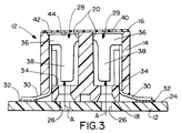
- FIGURE 3 is a vertical section, on an enlarged scale, transversely through the connector assembly mounted to the printed circuit board.
- Referring to the drawings in greater detail, the invention is directed to a system for mounting a connector assembly, such as a connector assembly generally designated 10, to a mounting surface of an electrical apparatus, such as a printed
circuit board 12, through the use of a vacuum-suction nozzle as described in the "Background" above. -
Connector assembly 10 includes adielectric housing block 14 of a conventional rectangular configuration and defining atop surface 16 and abottom surface 18. A plurality of open-ended, terminal-receiving passages 20 (Fig. 2) extend between the top and bottom surfaces of the housing. A plurality ofmounting pegs 22 depend from the bottom surface of the housing whereby the connector assembly is adapted for mounting the bottom surface adjacent a top ormounting surface 24 of printedcircuit board 12. As seen in Figure 3, the printed circuit board has a plurality ofholes 26 in alignment or registry with the through passages in the connector assembly. - A plurality of electrical terminals, generally designated 28, are mounted in
passages 22 ofhousing 14 and includetail portions 30 projecting from the bottom open ends of the through passages for interconnection to circuitry on the printed circuit board, particularly to circuit traces orpads 32 ontop surface 24 of the board. Actually, as seen in Figure 3,tail portions 30 ofterminals 28 project throughsmall passageways 34 ofhousing 14, the passageways being considered part of the throughpassages 20.Terminals 28 also includereceptacle portions 36 located withinpassages 20. In the alternative,tails 30 could extend downward into holes in the board for soldering thereto. - Each
terminal 28 includes a pair of inwardly biasedcantilevered contact arms 38 which are effective for making electrical interengagement with terminal pins of a complementary connector from the opposite or bottom side of printedcircuit board 12. The terminal pins of the complementary connector would be inserted in the direction of arrows "A" (Fig. 3) throughholes 26 in the printed circuit board and intopassages 20 ofhousing 14 whereupon the terminal pins will interengage withspring contact arms 38 ofterminal receptacle portions 36. The terminals are top-loaded into respective ones ofpassages 20 inhousing 14 in the direction of arrows "B" (Fig. 2). Once the terminals are top-loaded into the passages,tail portions 30 are bent transversely outwardly as shown in Figure 3, whereupon the tail portions can be surface soldered tocircuit traces 32 ontop surface 24 of the printed circuit board. - At this point, it should be understood that such terms as "top", "bottom", etc. are used herein and in the claims hereof for reference purposes only in order to provide a clear and concise understanding of the invention. Such terms are not to be limiting, because, as is well known in the art, electrical connector assemblies such as
connector assembly 10 are used in omni-directional applications. - The invention contemplates an improved system for facilitating manipulating and
positioning connector assembly 10 through the use of a vacuum-suction nozzle. To that end, athin film 40 is secured totop surface 16 ofhousing 14 for covering the open ends ofpassages 20 in the top surface. The film provides a smooth top surface area 42 (Fig. 2) for engagement by the vacuum-suction nozzle for manipulating and positioning the connector assembly. Preferably, the film has an adhesive on its bottom surface 44 (Fig. 3) for securing the film to the connector block. - Although the entire
top surface 16 ofhousing 14 is shown herein as being covered byfilm 42, it should be understood that the film need not cover the entire surface as long as there is a smooth top surface area of a size sufficient for engagement by a particular size of vacuum-suction nozzle. In assembly,terminals 28 are top loaded intopassages 20 in the housing, and the adhesive-backed film then is adhered to the top surface of the housing, covering the top open ends of the passages in at least an area sufficient for engagement by the vacuum-suction nozzle. - With
film 42 in place, the terminal pins of a complementary connector may only be mated to theterminals 28 ofconnector assembly 10 from the bottom. However, if a top mating connector is desired, such film may be removed after the soldering process. - It will be understood that the invention may be embodied in other specific forms without departing from the spirit or central characteristics thereof. The present examples and embodiments, therefore, are to be considered in all respects as illustrative and not restrictive, and the invention is not to be limited to the details given herein.
Claims (5)
- A system for mounting a connector assembly (10) to a mounting surface (24) of an electrical apparatus (12) through the use of a vacuum-suction nozzle, comprising:
a connector assembly (10) including a dielectric housing (14) adapted to be positioned adjacent said mounting surface (24), the housing having a top surface and a bottom surface with a plurality of terminal-receiving through passages (20) extending therebetween, the bottom surface being adapted to be mounted to the mounting surface of the electrical apparatus,
a plurality of electrical terminals (28) mounted in the passages and including solder tail portions (30) projecting from first open ends of the through passages for solder interconnection to circuitry (32) of the electrical apparatus, and
a film (40) secured to the top surface of the housing covering second open ends of at least some of the through passages to provide a smooth surface area (42) for engagement by the vacuum-suction nozzle for manipulating and positioning the connector assembly. - The system of claim 1 wherein said film (40) has an adhesive on one side (44) thereof for securing to the housing.
- The system of claim 1 wherein the connector assembly is mounted to a printed circuit board, and said terminal-receiving through passages are positioned to align with holes (26) in the printed circuit board.
- The system of claim 3 wherein said film (40) is flexible.
- The system of claim 3 wherein said solder tails (30) are bent generally parallel to the bottom surface (18) of the housing (14) for soldering to circuit traces (32) on a surface (24) of the printed circuit board (12).
Applications Claiming Priority (2)
| Application Number | Priority Date | Filing Date | Title |
|---|---|---|---|
| US89946 | 1993-07-08 | ||
| US08/089,946 US5383797A (en) | 1993-07-08 | 1993-07-08 | System for handling electrical connectors by a vacuum-suction nozzle |
Publications (2)
| Publication Number | Publication Date |
|---|---|
| EP0633634A2 true EP0633634A2 (en) | 1995-01-11 |
| EP0633634A3 EP0633634A3 (en) | 1996-05-08 |
Family
ID=22220335
Family Applications (1)
| Application Number | Title | Priority Date | Filing Date |
|---|---|---|---|
| EP94109922A Withdrawn EP0633634A3 (en) | 1993-07-08 | 1994-06-28 | System for handling electrical connectors by a vacuum-suction nozzle. |
Country Status (3)
| Country | Link |
|---|---|
| US (1) | US5383797A (en) |
| EP (1) | EP0633634A3 (en) |
| SG (1) | SG45189A1 (en) |
Cited By (5)
| Publication number | Priority date | Publication date | Assignee | Title |
|---|---|---|---|---|
| EP0708586A1 (en) * | 1994-10-20 | 1996-04-24 | Thomas & Betts Corporation | Methods of enabling transportation of articles |
| EP0836372A2 (en) * | 1996-10-10 | 1998-04-15 | Erwin Hagn | Method and apparatus to create a sucking surface on an object and electrical component built this way |
| GB2320132A (en) * | 1996-12-04 | 1998-06-10 | Ibm | Handling electronic modules |
| US5938456A (en) * | 1995-04-19 | 1999-08-17 | Methode Electronics, Inc. | Low profile electrical connector |
| DE19901962A1 (en) * | 1999-01-19 | 2000-07-20 | Erni Elektroapp | Mounting method for electrical plug connectors involves bending or folding holding unit as result of mounting movement of further component when further component is being mounted |
Families Citing this family (23)
| Publication number | Priority date | Publication date | Assignee | Title |
|---|---|---|---|---|
| US5651684A (en) * | 1995-05-31 | 1997-07-29 | Berg Technology, Inc. | Vacuum pick up cap for use in manipulating receptacles |
| US5967837A (en) * | 1996-10-01 | 1999-10-19 | Alps Automotive, Inc. | Assembly for connecting an electric/electronic device to a printed circuit board |
| US6083025A (en) * | 1997-03-05 | 2000-07-04 | Ryosei Electro-Circuit Systems Ltd. | Connector |
| US6015305A (en) * | 1997-07-10 | 2000-01-18 | Hon Hai Precision Ind. Co., Ltd. | Holding device for mounting connector on board |
| JPH1140288A (en) * | 1997-07-17 | 1999-02-12 | Nec Corp | Surface mount connector |
| CN1091310C (en) * | 1997-12-01 | 2002-09-18 | 鸿海精密工业股份有限公司 | Connector combination with auxiliary device |
| US6270374B1 (en) * | 1998-01-20 | 2001-08-07 | Berg Technology, Inc. | Electrical connector with wafer for video positioning and surface mount holding feature |
| CN1088927C (en) * | 1998-02-27 | 2002-08-07 | 鸿海精密工业股份有限公司 | Connector with auxiliary device |
| JP4346723B2 (en) * | 1999-01-28 | 2009-10-21 | モレックス インコーポレイテド | Electrical connector |
| TW433633U (en) * | 1999-04-09 | 2001-05-01 | Hon Hai Prec Ind Co Ltd | Auxiliary installation device for electrical connector |
| US6558174B1 (en) * | 2001-12-28 | 2003-05-06 | Hon Hai Precision Ind. Co., Ltd. | Pick-and-place device of CPU socket |
| US6927339B2 (en) | 2002-01-23 | 2005-08-09 | Tyco Electronics Corporation | Cover for electronic components and method of using same during component assembly |
| TW556990U (en) * | 2002-04-12 | 2003-10-01 | Hon Hai Prec Ind Co Ltd | Pick up device of electrical connector |
| US6753474B2 (en) * | 2002-09-18 | 2004-06-22 | Tyco Electronics Corporation | Pick and place cover for multiple terminal electronic components |
| US6604366B1 (en) * | 2002-09-19 | 2003-08-12 | Raytheon Company | Solid cryogen cooling system for focal plane arrays |
| TWM249277U (en) * | 2003-07-18 | 2004-11-01 | Hon Hai Prec Ind Co Ltd | Electrical connector assembly |
| TWM251313U (en) * | 2003-08-13 | 2004-11-21 | Hon Hai Prec Ind Co Ltd | Electrical connector |
| TWM299396U (en) * | 2006-01-20 | 2006-10-11 | Hon Hai Prec Ind Co Ltd | An electrical connector with pick-up cap |
| US7497700B2 (en) * | 2006-09-22 | 2009-03-03 | Hon Hai Precision Ind. Co., Ltd. | Electrical connector |
| CN201130742Y (en) * | 2007-08-24 | 2008-10-08 | 富士康(昆山)电脑接插件有限公司 | Electric connector as well as electric connector assembly |
| TWM373037U (en) * | 2009-07-21 | 2010-01-21 | Hon Hai Prec Ind Co Ltd | Electrical connector |
| CN201608386U (en) * | 2009-09-04 | 2010-10-13 | 富士康(昆山)电脑接插件有限公司 | Electric connector |
| TW201434221A (en) * | 2013-02-18 | 2014-09-01 | Hon Hai Prec Ind Co Ltd | Pick-up cap and electrical connector assembly thereof |
Citations (2)
| Publication number | Priority date | Publication date | Assignee | Title |
|---|---|---|---|---|
| DE3710184A1 (en) * | 1987-03-27 | 1988-10-13 | Siemens Ag | Electric component |
| US4920636A (en) * | 1988-05-11 | 1990-05-01 | E. I. Du Pont De Nemours And Company | Pin alignment apparatus and method |
Family Cites Families (7)
| Publication number | Priority date | Publication date | Assignee | Title |
|---|---|---|---|---|
| US3525143A (en) * | 1967-03-24 | 1970-08-25 | Conalco Metals Inc | Method of dip soldering electrical tube sockets |
| US4645278A (en) * | 1985-09-09 | 1987-02-24 | Texas Instruments Incorporated | Circuit panel connector, panel system using the connector, and method for making the panel system |
| US4910867A (en) * | 1988-05-27 | 1990-03-27 | Amp Incorporated | Method of forming a sealed electrical connector |
| US5055971A (en) * | 1989-12-21 | 1991-10-08 | At&T Bell Laboratories | Magnetic component using core clip arrangement operative for facilitating pick and place surface mount |
| US5147209A (en) * | 1990-04-16 | 1992-09-15 | Mckenzie Socket Technology, Inc. | Intermediary adapter-connector |
| JP2576105Y2 (en) * | 1991-07-15 | 1998-07-09 | ケル株式会社 | Auxiliary tool for connector suction |
| JPH0744079Y2 (en) * | 1991-12-09 | 1995-10-09 | モレックス インコーポレーテッド | Surface mount connector auto mount cover |
-
1993
- 1993-07-08 US US08/089,946 patent/US5383797A/en not_active Expired - Lifetime
-
1994
- 1994-06-28 EP EP94109922A patent/EP0633634A3/en not_active Withdrawn
- 1994-06-28 SG SG1996001102A patent/SG45189A1/en unknown
Patent Citations (2)
| Publication number | Priority date | Publication date | Assignee | Title |
|---|---|---|---|---|
| DE3710184A1 (en) * | 1987-03-27 | 1988-10-13 | Siemens Ag | Electric component |
| US4920636A (en) * | 1988-05-11 | 1990-05-01 | E. I. Du Pont De Nemours And Company | Pin alignment apparatus and method |
Cited By (9)
| Publication number | Priority date | Publication date | Assignee | Title |
|---|---|---|---|---|
| EP0708586A1 (en) * | 1994-10-20 | 1996-04-24 | Thomas & Betts Corporation | Methods of enabling transportation of articles |
| US5938456A (en) * | 1995-04-19 | 1999-08-17 | Methode Electronics, Inc. | Low profile electrical connector |
| EP0836372A2 (en) * | 1996-10-10 | 1998-04-15 | Erwin Hagn | Method and apparatus to create a sucking surface on an object and electrical component built this way |
| EP0836372A3 (en) * | 1996-10-10 | 1998-07-01 | Erwin Hagn | Method and apparatus to create a sucking surface on an object and electrical component built this way |
| GB2320132A (en) * | 1996-12-04 | 1998-06-10 | Ibm | Handling electronic modules |
| US6049464A (en) * | 1996-12-04 | 2000-04-11 | International Business Machines Corporation | Electronic modules manufacturing |
| DE19901962A1 (en) * | 1999-01-19 | 2000-07-20 | Erni Elektroapp | Mounting method for electrical plug connectors involves bending or folding holding unit as result of mounting movement of further component when further component is being mounted |
| US6379170B1 (en) | 1999-01-19 | 2002-04-30 | Erni Elektroapparate Gmbh | Method of mounting electrical plug-in connections and auxiliary mounting means for carrying out the method |
| DE19901962B4 (en) * | 1999-01-19 | 2006-05-11 | Erni Elektroapparate Gmbh | Method for mounting electrical connectors and mounting aid for performing the method |
Also Published As
| Publication number | Publication date |
|---|---|
| SG45189A1 (en) | 1998-01-16 |
| EP0633634A3 (en) | 1996-05-08 |
| US5383797A (en) | 1995-01-24 |
Similar Documents
| Publication | Publication Date | Title |
|---|---|---|
| US5383797A (en) | System for handling electrical connectors by a vacuum-suction nozzle | |
| US5242311A (en) | Electrical connector header with slip-off positioning cover and method of using same | |
| EP0564955B1 (en) | Edge connector for a printed circuit board | |
| US5498167A (en) | Board to board electrical connectors | |
| EP1049202B1 (en) | Electrical connector | |
| EP0548583A1 (en) | Header cover | |
| US5899760A (en) | Connector assembly | |
| US5580269A (en) | Surface mount connector | |
| US5704807A (en) | Surface mountable retention bracket for electrical connectors | |
| US6733305B2 (en) | Board-to-board electrical connector assembly | |
| US7066756B2 (en) | Apparatus for contacting a conductive surface by means of a pin connector | |
| EP3676912B1 (en) | Usb-c plug with surface mount contact points | |
| US7014506B2 (en) | Board mounted memory card connector | |
| EP0567006A1 (en) | Edge connector for a printed circuit board or the like | |
| US6135795A (en) | Electrical connector with cover | |
| US7052286B2 (en) | Electrical connector with cover | |
| US6095824A (en) | Electrical connector assembly | |
| US6623281B2 (en) | Mounting electronic components on circuit boards | |
| EP0755101A3 (en) | High density card edge connection system with outrigger and sequentially connected contacts | |
| US6462955B1 (en) | Component alignment casing system | |
| US5562499A (en) | Multiposition electrical connector filter adapter | |
| EP0921610A2 (en) | Electrical connector assembly for mounting on a printed circuit board and method for mounting it | |
| US5439400A (en) | Disposable electrical connector header | |
| US6328577B1 (en) | High density electric connector set | |
| US6685505B1 (en) | Electrical connector assembly having ground member |
Legal Events
| Date | Code | Title | Description |
|---|---|---|---|
| PUAI | Public reference made under article 153(3) epc to a published international application that has entered the european phase |
Free format text: ORIGINAL CODE: 0009012 |
|
| AK | Designated contracting states |
Kind code of ref document: A2 Designated state(s): DE FR GB IT |
|
| PUAL | Search report despatched |
Free format text: ORIGINAL CODE: 0009013 |
|
| AK | Designated contracting states |
Kind code of ref document: A3 Designated state(s): DE FR GB IT |
|
| 17P | Request for examination filed |
Effective date: 19961024 |
|
| 17Q | First examination report despatched |
Effective date: 19980218 |
|
| STAA | Information on the status of an ep patent application or granted ep patent |
Free format text: STATUS: THE APPLICATION IS DEEMED TO BE WITHDRAWN |
|
| 18D | Application deemed to be withdrawn |
Effective date: 19980829 |