EP0635711A2 - Filtration and dispensing device and method for a liquid - Google Patents
Filtration and dispensing device and method for a liquid Download PDFInfo
- Publication number
- EP0635711A2 EP0635711A2 EP94202116A EP94202116A EP0635711A2 EP 0635711 A2 EP0635711 A2 EP 0635711A2 EP 94202116 A EP94202116 A EP 94202116A EP 94202116 A EP94202116 A EP 94202116A EP 0635711 A2 EP0635711 A2 EP 0635711A2
- Authority
- EP
- European Patent Office
- Prior art keywords
- liquid
- test element
- cover
- test
- container
- Prior art date
- Legal status (The legal status is an assumption and is not a legal conclusion. Google has not performed a legal analysis and makes no representation as to the accuracy of the status listed.)
- Granted
Links
Images


Classifications
-
- G—PHYSICS
- G01—MEASURING; TESTING
- G01N—INVESTIGATING OR ANALYSING MATERIALS BY DETERMINING THEIR CHEMICAL OR PHYSICAL PROPERTIES
- G01N35/00—Automatic analysis not limited to methods or materials provided for in any single one of groups G01N1/00 - G01N33/00; Handling materials therefor
- G01N35/00029—Automatic analysis not limited to methods or materials provided for in any single one of groups G01N1/00 - G01N33/00; Handling materials therefor provided with flat sample substrates, e.g. slides
-
- G—PHYSICS
- G01—MEASURING; TESTING
- G01N—INVESTIGATING OR ANALYSING MATERIALS BY DETERMINING THEIR CHEMICAL OR PHYSICAL PROPERTIES
- G01N1/00—Sampling; Preparing specimens for investigation
- G01N1/28—Preparing specimens for investigation including physical details of (bio-)chemical methods covered elsewhere, e.g. G01N33/50, C12Q
- G01N1/40—Concentrating samples
- G01N1/4077—Concentrating samples by other techniques involving separation of suspended solids
-
- G—PHYSICS
- G01—MEASURING; TESTING
- G01N—INVESTIGATING OR ANALYSING MATERIALS BY DETERMINING THEIR CHEMICAL OR PHYSICAL PROPERTIES
- G01N35/00—Automatic analysis not limited to methods or materials provided for in any single one of groups G01N1/00 - G01N33/00; Handling materials therefor
- G01N35/10—Devices for transferring samples or any liquids to, in, or from, the analysis apparatus, e.g. suction devices, injection devices
- G01N35/1095—Devices for transferring samples or any liquids to, in, or from, the analysis apparatus, e.g. suction devices, injection devices for supplying the samples to flow-through analysers
Definitions
- This invention relates to a filtration and dispensing device and method of using such a device in the field of clinical diagnostic analyzers and is more particularly concerned with the filtering and transferring of a patient sample on to a test element.
- a quantity of patient liquid is dispensed on to a test slide element having at least one dried reagent layer with which the liquid interacts to produce a detectable signal for sensing the analyte of interest.
- filtering techniques in which a quantity of patient liquid is added to one end of a filter and separated.
- the filtered liquid then directly passes into a container for holding the filtered liquid from whence the liquid can be aspirated into a conventional pipette tip for metering on to a test element.
- the separated liquid may be retained at one end of the filter after being passed therethrough.
- a predetermined quantity of liquid is dispensed from the orifice of a pipette tip suspended a short distance above the test element.
- the point source delivers the liquid in the form of a droplet which strikes the test element in a localized area.
- Biological liquids such as serum, however, vary in terms of their spreadability (diffusivity) horizontally across a test element surface. For example, a patient sample having a higher concentration of lipids, or lipo-proteins, will not spread as easily as one with a lower concentration due to its higher viscosity. The inability to spread, and further the inability of some liquids to spread homogeneously, may produce inaccuracies in the detection of an analyte of interest.
- the accurate dispensing of the liquid on to the surface of a test element is also dependent upon a number of other factors, such as adhesion of the liquid to the tip, flow characteristics of the tip nozzle, the distance of the tip from the test element, the air flow in the vicinity of the tip, and so forth.
- Spreading layers typically provided for in the chemistry portion of a test element provide for horizontal as well as vertical diffusivity across the dried reagent layer(s); however, it is possible that the spreading will not be homogenous.
- the manufacture of a porous spreading layer to horizontally distribute the sample droplet is expensive.
- a further problem has been to provide a container for storing a patient sample from which a number of patient samples could be transferred to the surface of a test element without the need for additional disposable parts.
- An additional problem has been to control the amount of dispensed volume to the test element from a container having filtration means so that a generally uniform and thin layer is transferred directly without the necessity for horizontally flowing the sample as required with point source metering.
- a method for filtering a liquid and dispensing a quantity of filtered liquid on to a test surface of a test element comprising the steps of:-
- a container for filtering and dispensing a biological liquid comprising :- a body portion having an entrance opening and an exit opening; filter means disposed between the entrance opening and the exit opening, the filter means having a surface adjacent the exit opening and wettable with the filtered liquid; characterized in that the container further includes: a cover section for closing off access of the wetted surface from the atmosphere; and transfer means for transferring liquid from the wettable surface to a test element.
- the filtered liquid is collected at the surface of the filter means adjacent the exit opening and transferred to a test element by direct contact using the transfer means.
- An advantageous feature of the invention is that no precise quantity of fluid is required to be aspirated or otherwise precisely delivered to the container; all that is necessary is that a quantity of fluid, sufficient to effectively coat a test element, be placed within the container.
- a further advantageous feature of the invention is that use of a container as herein described allows multiple tests to be performed while using the same container, thereby reducing the number of disposables, and provides a cheaper and improved means for delivering filtered liquid to a test element.
- a further advantageous feature is that by delivering a quantity of liquid uniformly to the test surface area of a test element, without consideration of flow characteristics, a smaller quantity of liquid is required to effectively coat the test element and provide an adequate basis of detection, even in the extreme outer portions of the detection area.
- a still further advantageous feature of the present invention is that a surface dispersed quantity, as defined below, can be delivered to the test volume of a test element all at once, providing a relatively constant concentration level of liquid across the detection read area without significant washout of the dried chemistry or transient liquid flow after delivery.
- the present invention is herein described in terms of the attached Figures. In the embodiments illustrated, reference is made to the terms “lower”, “upper”, “top”, “bottom”, and so forth. These descriptions are to more clearly describe the embodiments shown, but are not limiting to the views shown.
- surface-dispersed quantity means, a quantity in which the surface area/volume ratio is approximately 1:1, for example, if a 10 ⁇ l volume has a 10mm2 dispersed surface area and a 1mm thickness, its ratio is 1:1. Ratios of 9:10 or 11:10 are included here.
- Container 2 is preferably made from a lightweight plastic material such as polystyrene, though almost any liquid-impermeable material can be used.
- container 2 has a cylindrical configuration, defining a circular cross-section, although either the configuration and/or cross-section can be easily varied for convenience.
- container 2 can be constructed such that sidewalls 4 taper inwardly from the top opening of the container, (not shown) thereby defining a conical configuration to provide a more stable structure, as well as a larger surface area for separation of a biological liquid.
- a first and a second filter, 10, 12, respectively are provided, each preferably having a pore size of less than 3 ⁇ m, for allowing liquid material to migrate therethrough, while retaining larger particulate matter, such as separated red blood cells.
- Each filter 10, 12 is sized to fit within interior portion 6 and is made from glass microfiber or cellulosic material, though other porous materials capable of filtering biological fluids may be used.
- the size and number of filters required may be varied to account for a number of other configurations other than the one herein described; for example, a single filter may be utilized, or a series of filters, each having differing pore sizes.
- second filter 12 is disposed directly beneath first filter 10 and has an exterior surface 14.
- exterior surface 14 is recessed within exit opening 8, formed by lip 26 extending downwardly from sidewalls 4.
- Exterior surface 14 is capable of retaining filtered liquid and is preferably defined by a circular configuration having a diameter D1.
- Second end 20 is preferably defined by a back, or posterior surface 24, while first end 18 is defined by a liquid supporting anterior surface 22.
- first end 18 is defined preferably and substantially over the entirety of anterior surface 22 by a plurality of substantially parallel V-shaped grooves 28, as defined by equally spaced rib members 30.
- each groove 28 is capable of supporting a quantity of liquid though alternate arrangements, with or without grooves, may be provided; for example, by providing grooves disposed in a diamond-like configuration, or by providing a textured surface (not shown) provided the surface is capable of supporting a liquid quantity thereon.
- one or more equalization grooves, or cross-channels can also be provided extending orthogonally to rib members 30 to avoid premature siphoning of liquid from surface 6.
- a relatively thin ring-like section 32 Disposed circumferentially about grooves 28 is a relatively thin ring-like section 32, made from a material, such as polypropylene with minimal protein adhesion, though other liquid-impermeable materials such as polymethacrylamine or copolymers with other acrylic amides or esters may be used.
- annular edge 36 is provided which is recessed from surface 22 sufficiently so that when cover 16 is engaged with the remainder of container 2 surfaces 22 and 14 can be brought into contact with one another.
- Cover 16 is also preferably sized so that diameter D2, corresponding to anterior surface 22 is at least equal to diameter D1 of exterior surface 14. In the embodiment illustrated, D1 is equal to 6mm and D2 is equal to 5mm. A relatively good seal is therefore provided when cover 16 is engaged with the remainder of container 2, minimizing air contact with exterior surface 16, once attached thereto.
- a knife-edge 44 used to remove excess liquid material from the cover once liquid has been transferred to liquid supporting surface 22.
- cover 16 is movably attached to the remainder of container 2 by a pair of telescopic arms 38 oppositely positioned along the exterior of sidewalls 4.
- arms 38 are pivotably mounted to cover 16 at mount 42, creating a first pivot axis -A-, and to sidewalls 4 at mount 40, creating a second pivot axis -B-.
- Each mount 40, 42 provides a bearing surface allowing cover 16 and arms 38, respectively, to rotate about axes -A- and -B-, though almost any form of pivoting means may be provided.
- cover 16 By also allowing arms 38 to be extendable, adequate clearance is provided to allow cover 16 to be rotatable about pivot axis -A-when extended to length L1, Figure 4, without contacting the remainder of container 2, while also allowing cover 16 to remain attached thereto.
- Other means for attaching to container 2, however, can be provided.
- cover 16 can be made fully removable from container 2 without the need for any attachment means.
- an unseparated biological liquid 46 such as whole blood
- any conventional dispensing means such as by pipetting (not shown) to container 2.
- the larger and heavier constituents 48 such as the red blood cells, are trapped within the pores of filters 10 and 12, respectively, while the remainder, or lighter phase of the liquid, continues to migrate downwardly under the force of gravity.
- the pores in filters 10, 12 are sufficiently large for allowing filtered liquid 46 to pass therethrough, wetting porous exterior surface 14.
- exterior surface 14, now glutted with filtered liquid 46 vertically expands along sidewalls 4 due to the corresponding increase in volume.
- cover 16 stays in contact with the remainder of container 2. This allows access to exterior surface 14 to be substantially closed to the atmosphere, preventing premature evaporation of filtered liquid 46 prior to transfer.
- Cover 16 is then preferably disengaged a nominal vertical distance, L2, from the remainder of container 2, by extending telescopic arms 38.
- L2 is roughly 0.5mm, Figure 5, though the particular disengagement length is not critical.
- Cover 16 is then re-engaged with container 2 by retracting telescopic arms 38, thereby placing surfaces 14 and 22 respectively, into contact with one another, surface 14 now having been glutted with liquid.
- Disengaging and re-engaging cover 16 as described allows air to be evacuated from grooves 28, thereby providing a site for transferring a portion of liquid 46 from wetted filter surface 14 to anterior liquid supporting surface 22.
- the small amount of air evacuated from grooves 28 is vented outward of container 2 at the edges between contacting surfaces 14, 22 in that the contact is not a perfect seal due to the porosity of filter material, though small vent holes (not shown) may be alternately supplied.
- Liquid migrating to anterior surface 22 adheres thereto due to surface tension in the form of a meniscus 52, Figure 6.
- cover 16 is extended a distance L3 from the remainder of container 2 by extending arms 38, Figure 6, and is then pivoted about pivot axis -B- ( Figure 4) allowing cover 16 to be positioned alongside of knife edge 44, Figure 7.
- Liquid-supporting surface 22 is then drawn across surface of knife edge 44, per arrows 53, Figure 7, by additionally pivoting arms 38 about axis -B- so that excess liquid in the form of meniscus 52 can be scraped away.
- the amount of liquid 54 remaining within grooves 28 following this operation is preferably sufficient to coat the test surface area of a test element 56, Figure 9.
- the energy supplied by drawing knife edge 44 against grooved surface 22 assists in removing any residual air pockets formed within grooves 28, allowing them to be filled with liquid 54 by capillary action.
- other removal means such as wicking using absorbant material or other scraping means may be used to remove the excess material.
- the still extended arms 38 are then pivoted about pivot axis -B-( Figure 8) until cover 16 is positioned directly below the remainder of container 2, preferably at length L3.
- Cover 16 is then preferably rotated about pivot axis -A- until liquid-supporting, or anterior surface 22 is facing in a downward direction, or facing in a direction opposite to that of the remainder of container 2, for aligning with a test element 56.
- Test element 56 is defined by a support frame 60, and a chemistry portion 58 containing at least one dried chemistry reactant layer.
- chemistry portion 58 is made up of a first top reactant layer 62 positioned above a second reactant layer 64, each being positioned upon a support 66.
- the top reactant layer can be a reagent layer, or alternatively be a spreading layer such as that described in US-A-3 992 158.
- a test surface area S is defined within chemistry portion 58 having a diameter D3.
- arms 38 are preferably retracted so that cover 16 is brought into contact with the remainder of container 2 to provide a more solid support.
- expansion of exterior surface 14 has occurred due to liquid swelling within filter 12.
- second end 20 will not contact the expanded exterior surface 14.
- second end 20 could be designed with a recessed surface (not shown) to avoid contacting surface 14 when cover 16 has been rotated.
- the entire assembled container 2 is then lowered by means (not shown) until grooves 28 are placed into compressive contact with chemistry portion 58.
- a downward compressive force F1 shown by arrow 68
- liquid 54 contained within grooves 28 is transferred directly and all at once to the test surface area S of test element 56.
- the surface area of liquid supporting surface 22 is preferably sized to be at least equal to test surface area S so that liquid can be transferred all at once to test element 56.
- a compressive force F1 of 0.14N (0.5ozf) is adequate to transfer liquid 54 to test element 56 without damaging the fragile chemistry portion 58.
- Container 2 can then be lifted away from test element 56 by any convenient means (not shown), leaving surface area S wetted with liquid.
- any liquid could be transferred using a container and the method described herein.
- a quantity of an already separated biological liquid such as serum, could be added to the container wherein the filter could serve as a means for supporting a quantity of liquid to be transferred to a test element.
- Another realized advantage is that the ability to transfer a volume of liquid uniformly and all at once to the entirety of a surface area as a surface-dispersed quantity to the test volume V of element 56 also negates the necessity for a horizontally diffusing spreading layer. Thereby, the manufacture of test slide elements, and in particular, the manufacture of the chemistry portion 58 contained therein is simplified.
Abstract
Description
- This invention relates to a filtration and dispensing device and method of using such a device in the field of clinical diagnostic analyzers and is more particularly concerned with the filtering and transferring of a patient sample on to a test element.
- In the field of testing of liquid analytes, particularly those using the so-called dried chemistry technology, a quantity of patient liquid is dispensed on to a test slide element having at least one dried reagent layer with which the liquid interacts to produce a detectable signal for sensing the analyte of interest.
- It has been required with clinical diagnostic analyzers, such as those manufactured by Eastman Kodak Company under the trademark "EKTACHEM™", which use the dried chemistry assay approach, that serum be separated from the whole blood sample prior to testing of the sample. Techniques for performing the separation are known and typically require centrifugation of a liquid sample to separate the heavier phase, (for example, that portion carrying the red blood cells), from the lighter phase, (for example, serum). These separation techniques are expensive in that they require a centrifuge, or other apparatus, to perform the separation. In addition, these techniques are time consuming in that they are usually performed off-line and separate from the analyzer prior to testing of the filtered sample.
- Alternatively, there are known filtering techniques in which a quantity of patient liquid is added to one end of a filter and separated. The filtered liquid then directly passes into a container for holding the filtered liquid from whence the liquid can be aspirated into a conventional pipette tip for metering on to a test element. Alternatively, the separated liquid may be retained at one end of the filter after being passed therethrough.
- There are associated problems with each described technique. In the first described method, additional processing steps are required to first collect the filtered liquid and subsequently to aspirate it into a tip for dispensing. In addition, using multiple pipette tips and containers increases the number of disposables.
- There are also a number of potential problems associated with the metering of a sample, filtered or otherwise, using conventional point source deposition methods.
- In the most common point source method, the pipette tip approach, a predetermined quantity of liquid is dispensed from the orifice of a pipette tip suspended a short distance above the test element. The point source delivers the liquid in the form of a droplet which strikes the test element in a localized area. Biological liquids, such as serum, however, vary in terms of their spreadability (diffusivity) horizontally across a test element surface. For example, a patient sample having a higher concentration of lipids, or lipo-proteins, will not spread as easily as one with a lower concentration due to its higher viscosity. The inability to spread, and further the inability of some liquids to spread homogeneously, may produce inaccuracies in the detection of an analyte of interest.
- The accurate dispensing of the liquid on to the surface of a test element is also dependent upon a number of other factors, such as adhesion of the liquid to the tip, flow characteristics of the tip nozzle, the distance of the tip from the test element, the air flow in the vicinity of the tip, and so forth. Spreading layers typically provided for in the chemistry portion of a test element provide for horizontal as well as vertical diffusivity across the dried reagent layer(s); however, it is possible that the spreading will not be homogenous. In addition, the manufacture of a porous spreading layer to horizontally distribute the sample droplet is expensive.
- In the second filtering technique described above, there are also a number of associated problems. Firstly, a predetermined quantity of patient liquid cannot be dispensed directly from the wetted end of a filter without potentially flooding the test element. Typically, it is required for only 10µl of liquid to be dispensed to the test surface area of a test element. In addition, liquid collected at the wetted end of a filter is prone to excessive contact with the atmosphere causing some of the collected liquid to evaporate prematurely, and require an excess of biological liquid be used.
- Therefore, there has been a problem in providing a method of directly providing whole blood or other unfiltered patient liquid to an analyzer wherein the whole blood can be separated and then transferred on to the test surface of a test element with a minimum of processing steps.
- A further problem has been to provide a container for storing a patient sample from which a number of patient samples could be transferred to the surface of a test element without the need for additional disposable parts.
- An additional problem has been to control the amount of dispensed volume to the test element from a container having filtration means so that a generally uniform and thin layer is transferred directly without the necessity for horizontally flowing the sample as required with point source metering.
- Specifically, in accordance with one aspect of the present invention, there is provided a method for filtering a liquid and dispensing a quantity of filtered liquid on to a test surface of a test element, the method comprising the steps of:-
- a) adding a liquid to filter means at a first end thereof;
- b) causing the liquid to pass through the filter means to an opposite end which is wetted by the filtered liquid;
characterized in that the method further includes the steps of:- - c) temporarily closing off access to the wetted end by the atmosphere;
- d) transferring at least some of the filtered liquid on the wetted end to an applicator; and
- e) applying liquid on the applicator to the test element.
- In accordance with another aspect of the present invention, there is provided a container for filtering and dispensing a biological liquid comprising :-
a body portion having an entrance opening and an exit opening;
filter means disposed between the entrance opening and the exit opening, the filter means having a surface adjacent the exit opening and wettable with the filtered liquid;
characterized in that the container further includes:
a cover section for closing off access of the wetted surface from the atmosphere; and
transfer means for transferring liquid from the wettable surface to a test element. - By this arrangement, the filtered liquid is collected at the surface of the filter means adjacent the exit opening and transferred to a test element by direct contact using the transfer means.
- An advantageous feature of the invention is that no precise quantity of fluid is required to be aspirated or otherwise precisely delivered to the container; all that is necessary is that a quantity of fluid, sufficient to effectively coat a test element, be placed within the container.
- A further advantageous feature of the invention is that use of a container as herein described allows multiple tests to be performed while using the same container, thereby reducing the number of disposables, and provides a cheaper and improved means for delivering filtered liquid to a test element.
- Yet a further advantageous feature is that by delivering a quantity of liquid uniformly to the test surface area of a test element, without consideration of flow characteristics, a smaller quantity of liquid is required to effectively coat the test element and provide an adequate basis of detection, even in the extreme outer portions of the detection area.
- A still further advantageous feature of the present invention is that a surface dispersed quantity, as defined below, can be delivered to the test volume of a test element all at once, providing a relatively constant concentration level of liquid across the detection read area without significant washout of the dried chemistry or transient liquid flow after delivery.
- For a better understanding of the present invention, reference will now be made, by way of example only, to the accompanying drawings in which:-
- Figure 1 is a sectioned side elevational view of one embodiment according to the present invention;
- Figure 2 is a bottom partial cross-sectional view of the container illustrated in Figure 1 taken along the line 2-2;
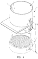
- Figure 3 is an isometric view of the cover portion of the container illustrated in Figure 1;
- Figure 4 is an isometric perspective view, rotated 90°, of the container shown in Figure 1, showing the disengagement of the cover portion shown in Figure 3;
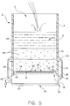
- Figure 5 is a partly sectioned side elevational view of the container illustrated in Figures 1 to 4 showing the filling of the container with a liquid to be filtered;
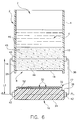
- Figure 6 is a partly sectioned side elevational view of the container shown in Figures 1 to 5 illustrating the disengagement of the cover portion after transfer of liquid has occurred;
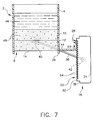
- Figure 7 is a partly sectioned side elevational view of the container illustrated in Figures 1 to 6 showing the removal of excess liquid material from the cover portion;
- Figure 8 is a sectioned side elevational view of the container illustrated in Figures 1 to 7 showing the orientation of the cover portion prior to the dispensing of liquid on to a test element; and
- Figure 9 is a sectioned side elevational view of the container assembly shown in Figures 1 to 8, illustrating the transfer of liquid on to a test element.
- The present invention is herein described in terms of the attached Figures. In the embodiments illustrated, reference is made to the terms "lower", "upper", "top", "bottom", and so forth. These descriptions are to more clearly describe the embodiments shown, but are not limiting to the views shown. In addition, the term "surface-dispersed quantity" means, a quantity in which the surface area/volume ratio is approximately 1:1, for example, if a 10µl volume has a 10mm² dispersed surface area and a 1mm thickness, its ratio is 1:1. Ratios of 9:10 or 11:10 are included here.
- Referring to Figure 1, there is provided a container, or
cup 2, havingsidewalls 4, and aninterior portion 6. Anentrance opening 7 is provided to allow liquid to entercontainer 2, as well as an oppositely disposedexit opening 8.Container 2 is preferably made from a lightweight plastic material such as polystyrene, though almost any liquid-impermeable material can be used. - In the embodiment illustrated,
container 2 has a cylindrical configuration, defining a circular cross-section, although either the configuration and/or cross-section can be easily varied for convenience. For example, in another preferred embodiment,container 2 can be constructed such thatsidewalls 4 taper inwardly from the top opening of the container, (not shown) thereby defining a conical configuration to provide a more stable structure, as well as a larger surface area for separation of a biological liquid. - Within
interior portion 6 is at least one porous filter. In the embodiment illustrated, a first and a second filter, 10, 12, respectively, are provided, each preferably having a pore size of less than 3µm, for allowing liquid material to migrate therethrough, while retaining larger particulate matter, such as separated red blood cells. Eachfilter interior portion 6 and is made from glass microfiber or cellulosic material, though other porous materials capable of filtering biological fluids may be used. In addition, the size and number of filters required may be varied to account for a number of other configurations other than the one herein described; for example, a single filter may be utilized, or a series of filters, each having differing pore sizes. - Referring to Figures 1 and 2,
second filter 12 is disposed directly beneathfirst filter 10 and has anexterior surface 14. Preferably,exterior surface 14 is recessed withinexit opening 8, formed bylip 26 extending downwardly fromsidewalls 4.Exterior surface 14 is capable of retaining filtered liquid and is preferably defined by a circular configuration having a diameter D1. - Movably attached to the bottom of
container 2 andadjacent exit opening 8 is a cover, orcap 16, having a first and asecond end Second end 20 is preferably defined by a back, orposterior surface 24, whilefirst end 18 is defined by a liquid supportinganterior surface 22. - Referring to Figures 1 and 3,
first end 18 is defined preferably and substantially over the entirety ofanterior surface 22 by a plurality of substantially parallel V-shapedgrooves 28, as defined by equally spacedrib members 30. In the embodiment illustrated, eachgroove 28 is capable of supporting a quantity of liquid though alternate arrangements, with or without grooves, may be provided; for example, by providing grooves disposed in a diamond-like configuration, or by providing a textured surface (not shown) provided the surface is capable of supporting a liquid quantity thereon. In addition to the above, one or more equalization grooves, or cross-channels (not shown) can also be provided extending orthogonally torib members 30 to avoid premature siphoning of liquid fromsurface 6. Disposed circumferentially aboutgrooves 28 is a relatively thin ring-like section 32, made from a material, such as polypropylene with minimal protein adhesion, though other liquid-impermeable materials such as polymethacrylamine or copolymers with other acrylic amides or esters may be used. - At the
outer periphery 34 offirst end 18, anannular edge 36 is provided which is recessed fromsurface 22 sufficiently so that whencover 16 is engaged with the remainder ofcontainer 2surfaces Cover 16 is also preferably sized so that diameter D2, corresponding toanterior surface 22 is at least equal to diameter D1 ofexterior surface 14. In the embodiment illustrated, D1 is equal to 6mm and D2 is equal to 5mm. A relatively good seal is therefore provided whencover 16 is engaged with the remainder ofcontainer 2, minimizing air contact withexterior surface 16, once attached thereto. - Along the exterior of
container 2 and disposed abovecover 16 and extending outwardly therefrom is a knife-edge 44 used to remove excess liquid material from the cover once liquid has been transferred to liquid supportingsurface 22. - Referring to Figures 3 and 4, cover 16 is movably attached to the remainder of
container 2 by a pair oftelescopic arms 38 oppositely positioned along the exterior ofsidewalls 4. In the embodiment illustrated,arms 38 are pivotably mounted to cover 16 atmount 42, creating a first pivot axis -A-, and to sidewalls 4 atmount 40, creating a second pivot axis -B-. Eachmount surface allowing cover 16 andarms 38, respectively, to rotate about axes -A- and -B-, though almost any form of pivoting means may be provided. By also allowingarms 38 to be extendable, adequate clearance is provided to allowcover 16 to be rotatable about pivot axis -A-when extended to length L1, Figure 4, without contacting the remainder ofcontainer 2, while also allowingcover 16 to remain attached thereto. Other means for attaching tocontainer 2, however, can be provided. Alternatively, cover 16 can be made fully removable fromcontainer 2 without the need for any attachment means. - One embodiment of the operation of the described
container 2 is shown in Figures 5 to 9. - Referring to Figure 5, a quantity of an unseparated biological liquid 46, such as whole blood, is added by any conventional dispensing means, such as by pipetting (not shown) to
container 2. Asliquid 46 migrates throughinterior portion 6, the larger andheavier constituents 48, such as the red blood cells, are trapped within the pores offilters filters exterior surface 14. Note thatexterior surface 14, now glutted with filteredliquid 46, vertically expands alongsidewalls 4 due to the corresponding increase in volume. - Preferably during the filling operation, cover 16 stays in contact with the remainder of
container 2. This allows access toexterior surface 14 to be substantially closed to the atmosphere, preventing premature evaporation of filteredliquid 46 prior to transfer. -
Cover 16 is then preferably disengaged a nominal vertical distance, L2, from the remainder ofcontainer 2, by extendingtelescopic arms 38. In the embodiment illustrated, L2 is roughly 0.5mm, Figure 5, though the particular disengagement length is not critical. -
Cover 16, is then re-engaged withcontainer 2 by retractingtelescopic arms 38, thereby placingsurfaces surface 14 now having been glutted with liquid. Disengaging and re-engagingcover 16 as described allows air to be evacuated fromgrooves 28, thereby providing a site for transferring a portion of liquid 46 from wettedfilter surface 14 to anteriorliquid supporting surface 22. The small amount of air evacuated fromgrooves 28 is vented outward ofcontainer 2 at the edges between contactingsurfaces anterior surface 22 adheres thereto due to surface tension in the form of ameniscus 52, Figure 6. - It is desirable to remove a portion of
meniscus 52 prior to deposition of the liquid sample on to a test element, in order to avoid potential flooding of the element. Referring to Figures 6 and 7, cover 16 is extended a distance L3 from the remainder ofcontainer 2 by extendingarms 38, Figure 6, and is then pivoted about pivot axis -B- (Figure 4) allowingcover 16 to be positioned alongside ofknife edge 44, Figure 7. - Liquid-supporting
surface 22 is then drawn across surface ofknife edge 44, perarrows 53, Figure 7, by additionally pivotingarms 38 about axis -B- so that excess liquid in the form ofmeniscus 52 can be scraped away. The amount ofliquid 54 remaining withingrooves 28 following this operation, is preferably sufficient to coat the test surface area of atest element 56, Figure 9. In addition to removing excess liquid, the energy supplied by drawingknife edge 44 against groovedsurface 22 assists in removing any residual air pockets formed withingrooves 28, allowing them to be filled withliquid 54 by capillary action. Note that other removal means, such as wicking using absorbant material or other scraping means may be used to remove the excess material. - Referring to Figures 8 and 9, the still extended
arms 38 are then pivoted about pivot axis -B-(Figure 8) untilcover 16 is positioned directly below the remainder ofcontainer 2, preferably at length L3.Cover 16 is then preferably rotated about pivot axis -A- until liquid-supporting, oranterior surface 22 is facing in a downward direction, or facing in a direction opposite to that of the remainder ofcontainer 2, for aligning with atest element 56. -
Test element 56, Figure 9, is defined by asupport frame 60, and achemistry portion 58 containing at least one dried chemistry reactant layer. In the embodiment illustrated,chemistry portion 58 is made up of a first top reactant layer 62 positioned above a second reactant layer 64, each being positioned upon a support 66. The top reactant layer can be a reagent layer, or alternatively be a spreading layer such as that described in US-A-3 992 158. A test surface area S is defined withinchemistry portion 58 having a diameter D3. - After
cover 16 has been rotated to align it withtest element 56,arms 38 are preferably retracted so thatcover 16 is brought into contact with the remainder ofcontainer 2 to provide a more solid support. As noted above, expansion ofexterior surface 14 has occurred due to liquid swelling withinfilter 12. By extendingsidewalls 4 vertically as shown bylip 26, however,second end 20 will not contact the expandedexterior surface 14. Other alternate means of modifying eithersecond end 20 orcontainer 2 may be employed. For example,second end 20 could be designed with a recessed surface (not shown) to avoid contactingsurface 14 whencover 16 has been rotated. - The entire assembled
container 2 is then lowered by means (not shown) untilgrooves 28 are placed into compressive contact withchemistry portion 58. As a downward compressive force F1, shown byarrow 68, is applied, liquid 54 contained withingrooves 28 is transferred directly and all at once to the test surface area S oftest element 56. The surface area ofliquid supporting surface 22 is preferably sized to be at least equal to test surface area S so that liquid can be transferred all at once to testelement 56. In the embodiment illustrated, a compressive force F1 of 0.14N (0.5ozf) is adequate to transfer liquid 54 to testelement 56 without damaging thefragile chemistry portion 58.Container 2 can then be lifted away fromtest element 56 by any convenient means (not shown), leaving surface area S wetted with liquid. - It can be seen that multiple tests can then be performed using a single container as described. Furthermore, by transferring a filtered liquid to the entirety of the test surface area of a test element as described, there is no further need for providing multiple disposable pipette tips.
- In addition, it is not required that a predetermined amount of liquid be added to the container in that a specific amount of sample is delivered to the entirety of the test element, the amount delivered being dependent on the configuration of the liquid-supporting surface.
- Furthermore, it should be apparent that literally any liquid could be transferred using a container and the method described herein. For example, a quantity of an already separated biological liquid, such as serum, could be added to the container wherein the filter could serve as a means for supporting a quantity of liquid to be transferred to a test element.
- Another realized advantage is that the ability to transfer a volume of liquid uniformly and all at once to the entirety of a surface area as a surface-dispersed quantity to the test volume V of
element 56 also negates the necessity for a horizontally diffusing spreading layer. Thereby, the manufacture of test slide elements, and in particular, the manufacture of thechemistry portion 58 contained therein is simplified.
Claims (20)
- A method for filtering a liquid and dispensing a quantity of filtered liquid on to a test surface (S) of a test element (56, 58, 60, 62, 64, 66), the method comprising the steps of:-a) adding a liquid to filter means (10, 12) at a first end thereof;b) causing the liquid to pass through the filter means (10, 12) to an opposite end (14) which is wetted by the filtered liquid;
characterized in that the method further includes the steps of:-c) temporarily closing off access to the wetted end (14) by the atmosphere;d) transferring at least some of the filtered liquid on the wetted end (14) to an applicator (22, 28, 30); ande) applying liquid on the applicator (22, 28, 30) to the test element (56, 58, 60, 62, 64, 66). - A method according to claim 1, wherein the step e) comprises opening the closed off access by moving the applicator (22, 28, 30) away from the wetted end (14), rotating the applicator (22, 28, 30) to direct liquid transferred thereto away from the wetted end (14), and contacting the rotated applicator (22, 28, 30) with the test element (56, 58, 60, 62, 64, 66).
- A method according to claim 1 or 2, wherein the step d) further comprises the step of contacting the wetted end (14) with an entire surface (22) of the applicator (22, 28, 30).
- A method according to claim 3, wherein step e) further comprises the step of placing the surface (22) in contact with the test surface area (S) of the test element (56, 58, 60, 62, 64, 66).
- A method according to any one of claims 1 to 4, further comprising the step of wiping excess liquid material from the applicator (22, 28, 30) prior to the step d).
- A method for filtering and dispensing a liquid on to a test surface (S) of a test element (56, 58, 60, 62, 64, 66), the method comprising the steps of:-a) adding a liquid to a container (2) which comprises a body portion (4) having an entrance opening (7) and an exit opening (8), filter means (10, 12) disposed between the entrance opening (7) and the exit opening (8) for filtering the liquid, and a removable cover (16, 18, 20, 22, 24);b) causing the liquid to pass through the filter means (10, 12) and to provide a meniscus (52) of the filtered liquid at the exit opening (8);
characterized in that the method further includes the steps of:-c) temporarily closing off access to the meniscus (52) by the atmosphere by engaging the cover (16, 18, 20, 22, 24) with the body portion (4);d) transferring some of the liquid meniscus (52) to the cover (16, 18, 20, 22, 24); ande) applying liquid on the cover (16, 18, 20, 22, 24) to a test element (56, 58, 60, 62, 64, 66). - A method according to claim 6, wherein the cover (16, 18, 20, 22, 24) comprises a transfer element (22, 28, 30) having a liquid-supporting surface (22) for supporting a liquid thereon, wherein step d) comprises the step of placing the liquid-supporting surface (22) in contact with the meniscus (52) on the filter means (10, 12).
- A method according to claim 7, wherein the cover (16, 18, 20, 22, 24) is movably attachable to the body portion (4), the method further comprising the steps of disengaging the cover (16, 18, 20, 22, 24) from the body portion (4) after step d), positioning the transfer element (22, 28, 30) to align the liquid-supporting surface (22) with the test surface (S) of the test element (56, 58, 60, 62, 64, 66), and re-engaging the cover (16, 18, 20, 22, 24) with the body portion (4) prior to step e).
- A method according to claim 7 or 8, wherein the body portion (4) comprises removal means (44) for removing excess material from the liquid-supporting surface (22), the removal means (44) comprising a knife edge attached to the body portion (4), the method further comprising the steps of positioning the liquid-supporting surface (22) adjacent the knife edge (44) and scraping the liquid-supporting surface (22) thereagainst.
- A method according to any one of claims 7 to 9, wherein the test element (56, 58, 60, 62, 64, 66) comprises a plastic supporting frame (60) and a test volume (V) comprising at least one dried reagent layer (62, 64) disposed on the supporting frame (60), and wherein step e) further comprises the step of placing the liquid-supporting surface (22) into compressive contact with the at least one dried reagent layer (62, 64), thereby transferring the liquid as a surface-dispersed quantity without the need for extensive horizontal flow over the test volume (V) of the test element (56, 58, 60, 62, 64, 66).
- A method according to any one of claims 7 to 10, further comprising the step of venting air from the liquid-supporting surface (22) prior to step d).
- A container (2) for filtering and dispensing a biological liquid comprising :-
a body portion (4) having an entrance opening (7) and an exit opening (8);
filter means (10, 12) disposed between the entrance opening (7) and the exit opening (8), the filter means (10, 12) having a surface (14) adjacent the exit opening (8) and wettable with the filtered liquid;
characterized in that the container further includes:
a cover section (16, 18, 20, 22, 24) for closing off access of the wetted surface (14) from the atmosphere; and
transfer means (22, 28, 30) for transferring liquid from the wettable surface (14) to a test element (56, 58, 60, 62, 64, 66). - A container according to claim 12, wherein the transfer means (22, 28, 30) comprises a surface (22) capable of supporting a quantity of filtered liquid thereon for transferring a surface-dispersed quantity all at once to the test surface area (S) of the test element (56, 58, 60, 62, 64).
- A container according to claim 13, wherein the transfer surface (22, 28, 30) comprises a plurality of grooves (28) extending over substantially the entirety of the transfer surface (22, 28, 30), the grooves (28) being sized to support a sufficient quantity of a body fluid to effectively coat the test surface area (S) of the test element (56, 58, 60, 62, 64).
- A container according to claim 14, wherein the grooves (28) are arranged in a diamond-like configuration over the transfer surface (22).
- A container according to any one of claims 12 to 15, further comprising removal means (44) for removing excess liquid material from the transfer means (22, 28, 30).
- A container according to claim 16, wherein the removal means (44) comprises a knife edge disposed on the body portion (4).
- A container according to any one of claims 12 to 17, wherein the cover section (16, 18, 20, 22, 24) includes the transfer means (22, 28, 30).
- A container according to any one of claims 12 to 18, further comprising attachment means (38, 40, 42) for movably attaching the cover section (16, 18, 20, 22, 24) to the body portion (4).
- A container according to claim 19, wherein the attachment means (38, 40, 42) comprises means for rotating the transfer means (22, 28, 30) so as to align the surface (22) with the wettable surface (10) and the test element (56, 58, 60, 62, 64, 66).
Applications Claiming Priority (2)
| Application Number | Priority Date | Filing Date | Title |
|---|---|---|---|
| US08/094,668 US5401467A (en) | 1993-07-21 | 1993-07-21 | Whole blood metering cup |
| US94668 | 1993-07-21 |
Publications (3)
| Publication Number | Publication Date |
|---|---|
| EP0635711A2 true EP0635711A2 (en) | 1995-01-25 |
| EP0635711A3 EP0635711A3 (en) | 1995-12-27 |
| EP0635711B1 EP0635711B1 (en) | 1998-06-17 |
Family
ID=22246465
Family Applications (1)
| Application Number | Title | Priority Date | Filing Date |
|---|---|---|---|
| EP94202116A Expired - Lifetime EP0635711B1 (en) | 1993-07-21 | 1994-07-19 | Filtration and dispensing device and method for a liquid |
Country Status (5)
| Country | Link |
|---|---|
| US (1) | US5401467A (en) |
| EP (1) | EP0635711B1 (en) |
| JP (1) | JPH0777526A (en) |
| AT (1) | ATE167576T1 (en) |
| DE (1) | DE69411089T2 (en) |
Cited By (2)
| Publication number | Priority date | Publication date | Assignee | Title |
|---|---|---|---|---|
| EP0932042A2 (en) * | 1998-01-27 | 1999-07-28 | Fuji Photo Film Co., Ltd. | Chemical analysis system and blood filtering unit |
| WO2006088377A1 (en) * | 2005-02-21 | 2006-08-24 | Norconserv As | A device and a method for analysis of an article of food by means of a test cup |
Families Citing this family (1)
| Publication number | Priority date | Publication date | Assignee | Title |
|---|---|---|---|---|
| US5589399A (en) * | 1994-10-21 | 1996-12-31 | First Medical, Inc. | System and method for plasma separation and measurement |
Citations (6)
| Publication number | Priority date | Publication date | Assignee | Title |
|---|---|---|---|---|
| GB2095404A (en) * | 1981-03-25 | 1982-09-29 | Fuji Photo Film Co Ltd | Method for supplying liquid samples to an analysis element |
| US4933092A (en) * | 1989-04-07 | 1990-06-12 | Abbott Laboratories | Methods and devices for the separation of plasma or serum from whole blood |
| WO1990010869A1 (en) * | 1989-03-08 | 1990-09-20 | Cholestech Corporation | Analyte assay device and apparatus |
| WO1991001364A1 (en) * | 1989-07-24 | 1991-02-07 | Imperial Cancer Research Technology Limited | Sample material transfer device |
| EP0476736A2 (en) * | 1990-08-27 | 1992-03-25 | Eastman Kodak Company | Pipettes |
| US5143849A (en) * | 1991-03-21 | 1992-09-01 | Eastman Kodak Company | Tip to surface spacing for optimum dispensing controlled by a detected pressure change in the tip |
Family Cites Families (17)
| Publication number | Priority date | Publication date | Assignee | Title |
|---|---|---|---|---|
| US603673A (en) * | 1898-05-10 | Strainer for milk-pails | ||
| US1067610A (en) * | 1912-03-07 | 1913-07-15 | August Ibbeken | Automatic back-surge seal for sewerage systems. |
| US3495926A (en) * | 1966-11-02 | 1970-02-17 | John F Naz | Method and apparatus for staining microslides |
| US3615257A (en) * | 1968-10-14 | 1971-10-26 | Becton Dickinson Co | Filter cassette and holder therefor |
| US3846077A (en) * | 1972-09-18 | 1974-11-05 | P Ohringer | Liquid sample collection tube |
| CA1054515A (en) * | 1975-12-17 | 1979-05-15 | Morris L. Givner | Ultrafiltration in pregnancy diagnosis |
| US4214993A (en) * | 1978-04-03 | 1980-07-29 | E. I. Du Pont De Nemours And Company | Apparatus for separating fluids |
| US4234317A (en) * | 1979-05-24 | 1980-11-18 | Analytical Products, Inc. | Apparatus and method for fractionation of lipoproteins |
| US4288316A (en) * | 1980-02-21 | 1981-09-08 | Hennessy Michael J | Fecal examining device |
| US4786471A (en) * | 1983-10-21 | 1988-11-22 | Baxter Travenol Laboratories, Inc. | Heterogeneous immunoassay method and assembly |
| US4693834A (en) * | 1986-05-05 | 1987-09-15 | Murex Corporation | Transverse flow diagnostic kit |
| US4636361A (en) * | 1985-11-18 | 1987-01-13 | Miklos Marian | Device for separating liquid fractions |
| US5000922A (en) * | 1986-02-19 | 1991-03-19 | Jon Turpen | Sample filtration, separation and dispensing device |
| US4965187A (en) * | 1986-09-10 | 1990-10-23 | Idexx Corporation | Method and apparatus for assaying whole blood |
| US4978504A (en) * | 1988-02-09 | 1990-12-18 | Nason Frederic L | Specimen test unit |
| US5084245A (en) * | 1988-11-07 | 1992-01-28 | Hygeia Sciences, Inc. | Assay device for swab borne analytes |
| US5019033A (en) * | 1989-12-18 | 1991-05-28 | Warner-Lambert Company | Ointment applicator and method of using |
-
1993
- 1993-07-21 US US08/094,668 patent/US5401467A/en not_active Expired - Lifetime
-
1994
- 1994-07-19 AT AT94202116T patent/ATE167576T1/en active
- 1994-07-19 EP EP94202116A patent/EP0635711B1/en not_active Expired - Lifetime
- 1994-07-19 DE DE69411089T patent/DE69411089T2/en not_active Expired - Fee Related
- 1994-07-20 JP JP6167996A patent/JPH0777526A/en active Pending
Patent Citations (6)
| Publication number | Priority date | Publication date | Assignee | Title |
|---|---|---|---|---|
| GB2095404A (en) * | 1981-03-25 | 1982-09-29 | Fuji Photo Film Co Ltd | Method for supplying liquid samples to an analysis element |
| WO1990010869A1 (en) * | 1989-03-08 | 1990-09-20 | Cholestech Corporation | Analyte assay device and apparatus |
| US4933092A (en) * | 1989-04-07 | 1990-06-12 | Abbott Laboratories | Methods and devices for the separation of plasma or serum from whole blood |
| WO1991001364A1 (en) * | 1989-07-24 | 1991-02-07 | Imperial Cancer Research Technology Limited | Sample material transfer device |
| EP0476736A2 (en) * | 1990-08-27 | 1992-03-25 | Eastman Kodak Company | Pipettes |
| US5143849A (en) * | 1991-03-21 | 1992-09-01 | Eastman Kodak Company | Tip to surface spacing for optimum dispensing controlled by a detected pressure change in the tip |
Cited By (3)
| Publication number | Priority date | Publication date | Assignee | Title |
|---|---|---|---|---|
| EP0932042A2 (en) * | 1998-01-27 | 1999-07-28 | Fuji Photo Film Co., Ltd. | Chemical analysis system and blood filtering unit |
| EP0932042A3 (en) * | 1998-01-27 | 2003-04-02 | Fuji Photo Film Co., Ltd. | Chemical analysis system and blood filtering unit |
| WO2006088377A1 (en) * | 2005-02-21 | 2006-08-24 | Norconserv As | A device and a method for analysis of an article of food by means of a test cup |
Also Published As
| Publication number | Publication date |
|---|---|
| EP0635711A3 (en) | 1995-12-27 |
| EP0635711B1 (en) | 1998-06-17 |
| US5401467A (en) | 1995-03-28 |
| DE69411089T2 (en) | 1999-03-11 |
| DE69411089D1 (en) | 1998-07-23 |
| ATE167576T1 (en) | 1998-07-15 |
| JPH0777526A (en) | 1995-03-20 |
Similar Documents
| Publication | Publication Date | Title |
|---|---|---|
| US4933291A (en) | Centrifugable pipette tip and pipette therefor | |
| US4046699A (en) | Access device for centrifugal separation assemblies | |
| US5284753A (en) | Multiple-site chemotactic test apparatus and method | |
| US4501496A (en) | Specimen slide for analysis of liquid specimens | |
| US4468410A (en) | Method and apparatus for producing a microscopic specimen slide | |
| US3969250A (en) | Apparatus for preparing liquid samples for analysis in automatic analyzers | |
| US4962044A (en) | Test tube filter/dispenser apparatus and method | |
| EP2326596A1 (en) | Multi-layer slides for analysis of urine sediments | |
| WO1994015212A1 (en) | Feces pick-up container for transportation | |
| EP0105489A2 (en) | Method and device for use in chemical reactions and analyses | |
| EP1901850A2 (en) | Slide deposition chamber | |
| US7758816B2 (en) | Large area cytocentrifuge sample chamber | |
| US7211225B2 (en) | Filter devices for depositing material and density gradients of material from sample suspension | |
| CA2040920C (en) | Capillary inoculator and assembly for inoculating multiple test sites and method of inoculation test sites therewith | |
| EP0635711B1 (en) | Filtration and dispensing device and method for a liquid | |
| CA2482560C (en) | Centrifugal cytology system, chamber block and method for the preparation of treated monolayers of sample material | |
| JPH05107251A (en) | Blood analyzer | |
| CN114728282A (en) | Material transfer device and method of use | |
| JPH0968484A (en) | Liquid sampler and sampling method | |
| EP4190451A1 (en) | Pipette tip and pipette system for capillary blood collection | |
| US4792432A (en) | Method for performing a liquid analysis and an analytical element for use in the method | |
| CA1087108A (en) | Serum skimmer | |
| GB2292702A (en) | Improved cytocentrifugation device |
Legal Events
| Date | Code | Title | Description |
|---|---|---|---|
| PUAI | Public reference made under article 153(3) epc to a published international application that has entered the european phase |
Free format text: ORIGINAL CODE: 0009012 |
|
| AK | Designated contracting states |
Kind code of ref document: A2 Designated state(s): AT BE CH DE DK FR GB IT LI NL SE |
|
| RAP1 | Party data changed (applicant data changed or rights of an application transferred) |
Owner name: CLINICAL DIAGNOSTIC SYSTEMS, INC. |
|
| RAP1 | Party data changed (applicant data changed or rights of an application transferred) |
Owner name: JOHNSON & JOHNSON CLINICAL DIAGNOSTICS, INC. |
|
| PUAL | Search report despatched |
Free format text: ORIGINAL CODE: 0009013 |
|
| RHK1 | Main classification (correction) |
Ipc: G01N 35/00 |
|
| AK | Designated contracting states |
Kind code of ref document: A3 Designated state(s): AT BE CH DE DK FR GB IT LI NL SE |
|
| 17P | Request for examination filed |
Effective date: 19960607 |
|
| 17Q | First examination report despatched |
Effective date: 19960723 |
|
| GRAG | Despatch of communication of intention to grant |
Free format text: ORIGINAL CODE: EPIDOS AGRA |
|
| GRAG | Despatch of communication of intention to grant |
Free format text: ORIGINAL CODE: EPIDOS AGRA |
|
| GRAH | Despatch of communication of intention to grant a patent |
Free format text: ORIGINAL CODE: EPIDOS IGRA |
|
| GRAH | Despatch of communication of intention to grant a patent |
Free format text: ORIGINAL CODE: EPIDOS IGRA |
|
| GRAA | (expected) grant |
Free format text: ORIGINAL CODE: 0009210 |
|
| AK | Designated contracting states |
Kind code of ref document: B1 Designated state(s): AT BE CH DE DK FR GB IT LI NL SE |
|
| PG25 | Lapsed in a contracting state [announced via postgrant information from national office to epo] |
Ref country code: NL Free format text: LAPSE BECAUSE OF FAILURE TO SUBMIT A TRANSLATION OF THE DESCRIPTION OR TO PAY THE FEE WITHIN THE PRESCRIBED TIME-LIMIT Effective date: 19980617 Ref country code: LI Free format text: LAPSE BECAUSE OF FAILURE TO SUBMIT A TRANSLATION OF THE DESCRIPTION OR TO PAY THE FEE WITHIN THE PRESCRIBED TIME-LIMIT Effective date: 19980617 Ref country code: IT Free format text: LAPSE BECAUSE OF FAILURE TO SUBMIT A TRANSLATION OF THE DESCRIPTION OR TO PAY THE FEE WITHIN THE PRESCRIBED TIME-LIMIT;WARNING: LAPSES OF ITALIAN PATENTS WITH EFFECTIVE DATE BEFORE 2007 MAY HAVE OCCURRED AT ANY TIME BEFORE 2007. THE CORRECT EFFECTIVE DATE MAY BE DIFFERENT FROM THE ONE RECORDED. Effective date: 19980617 Ref country code: CH Free format text: LAPSE BECAUSE OF FAILURE TO SUBMIT A TRANSLATION OF THE DESCRIPTION OR TO PAY THE FEE WITHIN THE PRESCRIBED TIME-LIMIT Effective date: 19980617 Ref country code: BE Free format text: LAPSE BECAUSE OF FAILURE TO SUBMIT A TRANSLATION OF THE DESCRIPTION OR TO PAY THE FEE WITHIN THE PRESCRIBED TIME-LIMIT Effective date: 19980617 Ref country code: AT Free format text: LAPSE BECAUSE OF FAILURE TO SUBMIT A TRANSLATION OF THE DESCRIPTION OR TO PAY THE FEE WITHIN THE PRESCRIBED TIME-LIMIT Effective date: 19980617 |
|
| REF | Corresponds to: |
Ref document number: 167576 Country of ref document: AT Date of ref document: 19980715 Kind code of ref document: T |
|
| REG | Reference to a national code |
Ref country code: CH Ref legal event code: EP |
|
| REF | Corresponds to: |
Ref document number: 69411089 Country of ref document: DE Date of ref document: 19980723 |
|
| PG25 | Lapsed in a contracting state [announced via postgrant information from national office to epo] |
Ref country code: SE Free format text: LAPSE BECAUSE OF FAILURE TO SUBMIT A TRANSLATION OF THE DESCRIPTION OR TO PAY THE FEE WITHIN THE PRESCRIBED TIME-LIMIT Effective date: 19980917 Ref country code: DK Free format text: LAPSE BECAUSE OF FAILURE TO SUBMIT A TRANSLATION OF THE DESCRIPTION OR TO PAY THE FEE WITHIN THE PRESCRIBED TIME-LIMIT Effective date: 19980917 |
|
| ET | Fr: translation filed | ||
| NLV1 | Nl: lapsed or annulled due to failure to fulfill the requirements of art. 29p and 29m of the patents act | ||
| REG | Reference to a national code |
Ref country code: CH Ref legal event code: PL |
|
| PLBE | No opposition filed within time limit |
Free format text: ORIGINAL CODE: 0009261 |
|
| STAA | Information on the status of an ep patent application or granted ep patent |
Free format text: STATUS: NO OPPOSITION FILED WITHIN TIME LIMIT |
|
| 26N | No opposition filed | ||
| PGFP | Annual fee paid to national office [announced via postgrant information from national office to epo] |
Ref country code: DE Payment date: 20010709 Year of fee payment: 8 |
|
| PGFP | Annual fee paid to national office [announced via postgrant information from national office to epo] |
Ref country code: FR Payment date: 20010712 Year of fee payment: 8 |
|
| PGFP | Annual fee paid to national office [announced via postgrant information from national office to epo] |
Ref country code: GB Payment date: 20010718 Year of fee payment: 8 |
|
| REG | Reference to a national code |
Ref country code: GB Ref legal event code: IF02 |
|
| PG25 | Lapsed in a contracting state [announced via postgrant information from national office to epo] |
Ref country code: GB Free format text: LAPSE BECAUSE OF NON-PAYMENT OF DUE FEES Effective date: 20020719 |
|
| PG25 | Lapsed in a contracting state [announced via postgrant information from national office to epo] |
Ref country code: DE Free format text: LAPSE BECAUSE OF NON-PAYMENT OF DUE FEES Effective date: 20030201 |
|
| GBPC | Gb: european patent ceased through non-payment of renewal fee |
Effective date: 20020719 |
|
| PG25 | Lapsed in a contracting state [announced via postgrant information from national office to epo] |
Ref country code: FR Free format text: LAPSE BECAUSE OF NON-PAYMENT OF DUE FEES Effective date: 20030331 |
|
| REG | Reference to a national code |
Ref country code: FR Ref legal event code: ST |