EP0635983A2 - Method and means for detecting people in image sequences - Google Patents
Method and means for detecting people in image sequences Download PDFInfo
- Publication number
- EP0635983A2 EP0635983A2 EP94304978A EP94304978A EP0635983A2 EP 0635983 A2 EP0635983 A2 EP 0635983A2 EP 94304978 A EP94304978 A EP 94304978A EP 94304978 A EP94304978 A EP 94304978A EP 0635983 A2 EP0635983 A2 EP 0635983A2
- Authority
- EP
- European Patent Office
- Prior art keywords
- image
- head
- processor
- human head
- sensing
- Prior art date
- Legal status (The legal status is an assumption and is not a legal conclusion. Google has not performed a legal analysis and makes no representation as to the accuracy of the status listed.)
- Withdrawn
Links
Images


Classifications
-
- H—ELECTRICITY
- H04—ELECTRIC COMMUNICATION TECHNIQUE
- H04N—PICTORIAL COMMUNICATION, e.g. TELEVISION
- H04N7/00—Television systems
- H04N7/14—Systems for two-way working
- H04N7/15—Conference systems
-
- G—PHYSICS
- G06—COMPUTING; CALCULATING OR COUNTING
- G06T—IMAGE DATA PROCESSING OR GENERATION, IN GENERAL
- G06T7/00—Image analysis
- G06T7/20—Analysis of motion
- G06T7/246—Analysis of motion using feature-based methods, e.g. the tracking of corners or segments
- G06T7/251—Analysis of motion using feature-based methods, e.g. the tracking of corners or segments involving models
-
- G—PHYSICS
- G06—COMPUTING; CALCULATING OR COUNTING
- G06T—IMAGE DATA PROCESSING OR GENERATION, IN GENERAL
- G06T7/00—Image analysis
- G06T7/20—Analysis of motion
- G06T7/254—Analysis of motion involving subtraction of images
-
- G—PHYSICS
- G06—COMPUTING; CALCULATING OR COUNTING
- G06V—IMAGE OR VIDEO RECOGNITION OR UNDERSTANDING
- G06V40/00—Recognition of biometric, human-related or animal-related patterns in image or video data
- G06V40/10—Human or animal bodies, e.g. vehicle occupants or pedestrians; Body parts, e.g. hands
- G06V40/103—Static body considered as a whole, e.g. static pedestrian or occupant recognition
-
- G—PHYSICS
- G06—COMPUTING; CALCULATING OR COUNTING
- G06V—IMAGE OR VIDEO RECOGNITION OR UNDERSTANDING
- G06V40/00—Recognition of biometric, human-related or animal-related patterns in image or video data
- G06V40/10—Human or animal bodies, e.g. vehicle occupants or pedestrians; Body parts, e.g. hands
- G06V40/16—Human faces, e.g. facial parts, sketches or expressions
- G06V40/161—Detection; Localisation; Normalisation
- G06V40/167—Detection; Localisation; Normalisation using comparisons between temporally consecutive images
-
- H—ELECTRICITY
- H04—ELECTRIC COMMUNICATION TECHNIQUE
- H04N—PICTORIAL COMMUNICATION, e.g. TELEVISION
- H04N7/00—Television systems
- H04N7/18—Closed-circuit television [CCTV] systems, i.e. systems in which the video signal is not broadcast
-
- G—PHYSICS
- G06—COMPUTING; CALCULATING OR COUNTING
- G06T—IMAGE DATA PROCESSING OR GENERATION, IN GENERAL
- G06T2207/00—Indexing scheme for image analysis or image enhancement
- G06T2207/10—Image acquisition modality
- G06T2207/10016—Video; Image sequence
-
- G—PHYSICS
- G06—COMPUTING; CALCULATING OR COUNTING
- G06T—IMAGE DATA PROCESSING OR GENERATION, IN GENERAL
- G06T2207/00—Indexing scheme for image analysis or image enhancement
- G06T2207/30—Subject of image; Context of image processing
- G06T2207/30196—Human being; Person
-
- G—PHYSICS
- G06—COMPUTING; CALCULATING OR COUNTING
- G06T—IMAGE DATA PROCESSING OR GENERATION, IN GENERAL
- G06T2207/00—Indexing scheme for image analysis or image enhancement
- G06T2207/30—Subject of image; Context of image processing
- G06T2207/30196—Human being; Person
- G06T2207/30201—Face
-
- H—ELECTRICITY
- H04—ELECTRIC COMMUNICATION TECHNIQUE
- H04N—PICTORIAL COMMUNICATION, e.g. TELEVISION
- H04N19/00—Methods or arrangements for coding, decoding, compressing or decompressing digital video signals
- H04N19/20—Methods or arrangements for coding, decoding, compressing or decompressing digital video signals using video object coding
Definitions
- This invention relates to methods and means for detecting people in image sequences, and particularly for locating people in video images to facilitate visual communication.
- Locating people in video images can facilitate automatic camera panning, interfacing of humans and machines, automatic security applications, human traffic monitoring, image compression and other applications.
- U.S. Patent No. 5,086,480 attempts to identify people in video images by subtracting corresponding image elements of subsequent images, thresholding the image elements against a luminous threshold to eliminate noise, filtering and clustering the resulting data sets, determining the minimum rectangle which will contain the sets, generating a border of finite thickness around the rectangles, and generating a head code book from the elements in the original images that correspond to the elements represented by the respective sets of data that fall within the respective borders.
- the patentee assumes that there is a moving head within any image which will provide the subtracted output. However, if a person in the image raises a hand, the disclosed method may confuse a hand and a head.
- An object of the invention is to improve systems for identifying persons in a series of images.
- Another object of the invention is to overcome the aforementioned difficulties.
- these objects are attained, by obtaining the difference between one image and a previous image to extract regions of motion; comparing local curvature extremes at the boundary of motion regions with a stored model of a human head; and identifying the local boundary corresponding to the model of the human head.
- the step of obtaining the difference between an image with a previous image includes digitizing the images before obtaining the difference.
- the step of comparing the local boundary curvature extremes includes calculating the local extremes of curvature of the boundaries before comparing them with the stored model.
- the step of comparing includes fitting a surrounding annular shape to the portion of the region boundary corresponding to a human head and neck.
- Fig. 1 is a block diagram of a system embodying features of the invention.
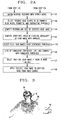
- Figs. 2A and 2B are flow charts illustrating the steps in a processor in Fig. 1 and embodying features of the invention.
- Fig. 3 is a picture of an image formed by subtracting the elements of one image from another according to an embodiment of the invention.
- Fig. 4 is a picture of the dilated image of Fig. 3.
- Fig. 5 is a block diagram showing details of a step in Fig. 2.
- Fig. 6 is a contour image of the image in Fig. 4.
- Figs. 7 to 10 are examples of images of correct detections from contours obtained from dilated frame-to-frame difference images with straight lines dray to indicate locations of local maxima of curvature at the necks.
- Figs. 11 to 22 are examples of dilated images of potential head and chests of persons to be found according to the invention.
- Figs. 11A to 22A are examples of contours resulting from processing of the dilated images in Figs. 11 to 22 according to the invention with annuluses drawn over the possible head portions of the contours, and showing confidence levels according to the invention.
- Fig. 22 is a flow chart showing details of a step in the chart of Fig. 2.
- Fig. 23 is a flow chart illustrating other steps embodying features of the invention.
- Fig. 24 is a block diagram of another system embodying the invention.
- Fig. 25 is a view of a video display showing operation of a system according to one aspect of the invention.
- a video camera VC1 passes detected video signals to a processor PR1 in the form of a computer with suitable storage and a central processing unit.
- a display DI1 displays the video output from the video camera VC1 on the basis of the processing by the processor PR1.
- the video camera VC1 determines whether a scene includes at least one person.
- the processor PR1 generates control signals which a viewer can direct either to the video camera VC1, to the display DI1, or both.
- the control signals point the video camera onto the scene so as to place the person in the scene in a desired location, preferably the center.
- the control signals place the person electronically at a desired position in the scene, preferably the center.
- a recorder RE1 such as a video cassette recorder, may record the processed signal from the processor PR1.
- the processor PR1 has a manual control or input MI1 which causes the display DI1 selectively to display the unprocessed output from the video camera VC1 or the processed video output, which centers or positions the person in the scene, from the processor PR1.
- a viewer camera VC1 can thereby choose alternately to display the unprocessed images from the video camera VC1 or the processed images, with a person centered or otherwise located from the processor PR1 where the processor PR1 controls the position of the video camera VC1.
- the selection of displays is entirely within the discretion of the viewer.
- Figs. 2 and 2A are flow diagrams illustrating steps performed by the processor PR1 to process the images from the video camera VC1.
- the processor PR1 in step 101 receives the video input from the camera VC1.
- the processor PR1 in step 104 digitizes the video input.
- the processor PR1 stores successive images from the video input, and in step 110 subtracts one of two successive images from the other, that is it subtracts picture elements of one of two successive images from corresponding picture elements of the other.
- the processor PR1 preferably subtracts elements of immediately successive frames (or images), but may go backwards a number of frames for the subtraction process.
- the processor PR1 forms absolute values of the elements in the subtracted images, and in step 117, compares it to a threshold value 120 stored in the processor PR1 and sets values greater than the threshold to 1 and values less than or equal to the threshold to zero to produce a binary motion image.
- the purpose of formation of absolute values, in step 114 and the comparison operation with a threshold value in step 117 is to remove temporal noise.
- the processor PR1 produces "segmentation" by subtracting elements of a previous image from corresponding elements of an image currently coming from the video camera VC1, taking the absolute value, and thresholding the result to remove temporal noise in accordance with the equation
- the value ⁇ represents the number of images or frames backwards which the processor PR1 selects for subtraction and preferably represents one frame or image.
- the processor PR1 includes a manually operable frame control FC to change the ⁇ to higher integral values and allow a viewer to improve detection of slow moving objects.
- the frame control FC may be automatic.
- the value T which represents the threshold value is selected to remove all the noise.
- the processor PR1 uses a lower threshold value T which generates an image with some randomly spaced, isolated noise pixels, and postpones removal of the remaining noise until a later processing stage.
- a user controls input which sets the value of the threshold T to eliminate remaining noise which can affect the accuracy of the object/background segmentation.
- Fig. 3 illustrates the result of the subtraction occurring in steps 101 to 120.
- the subtraction often produces imperfect object segmentation in normal scenes where the processor PR1 may not recognize the head HE on the object OB in Fig. 3 as a head because of the gap GA near the center of the head.
- the processor PR1 in step 124 dilates the binary motion image to fill the gaps in the binary motion image as shown in the dilated object DO in Fig. 4. This filling does affect the resolution and accuracy.
- morphological closing which is dilation followed by erosion fills the gaps.
- a preferred embodiment of the invention omits the erosion step and accepts the fact that the object size will increase slightly as a result of dilation.
- Fig. 4 illustrates the dilated figure and how it improves object segmentation.
- a hand HA appears in both Fig. 3 and Fig. 4.
- step 127 the processor PR identifies the boundaries of the difference image by tracing the contours of the outline of the dilated difference image shown in Fig. 4.
- the processor PR1 finds the coordinate values of the region boundaries (x(i) and y(i)) .
- step 130 the processor PR1 independently smoothes the coordinate values of the region boundaries with a rectangular filter of length 2k + 1 where k is a parameter for computing the k-curvature of the contour. Determination of the k-curvature of a contour is known and appears in the article by A. Rosenfeld, and A. Kak, Digital Picture Processing , Academic Press, 1976, ISBN 0-12-597360-8. It also appears in the 1983 SPIE article from the SPIE Conference on Robot Vision and Sensory Control, in Cambridge, Massachusetts, entitled Locating Randomly Oriented Objects from Partial View , by Jakub Segen. The components of the step 130 appear in Fig. 5 as steps 501 to 524. They start with the smoothing step 501, the slope determining step 504, and the computing step 507.
- the curvature is determined otherwise.
- k-curvature is simple and sufficient for the purposes of this invention.
- the processor PR1 smoothes the curvature of the image; determines the derivatives of the curvature in step 514; locates the significant zero crossings of the derivative of the curvature in step 517; and determines the normal to the curve at each significant zero crossing in step 520 using two points on the contour, each separated by the Euclidean distance k from the point of the significant zero crossing.
- it stores parameters for each of these "feature" points (i.e. zero crossings of the derivative), namely the x-y location, curvature, and the angle of the normal to the curve.
- the curvature is positive for convex features and negative for concave features.
- the processor PR1 stores the feature points in the order that they appear in the contour which the processor traces clockwise.
- Fig. 6 illustrates the results of contour tracing in step 127 and the calculation of local boundary curvature extremes set forth in step 130 and in steps 501 to 524.
- Fig. 6 includes the normals NO as well the traced contours CN.
- the processor PR1 has reduced the data from regions to contours to feature points.
- the processor PR1 now proceeds to locate features corresponding to head and neck shapes from the set of feature points.
- the processor PR1 uses a simple, hard coded (not learned) model of the shape of the head and neck in the model input step 134.
- a representative RE of the model appears with step 134.
- step 137 the processor PR1 matches regional features with the stored model.
- the processor PR1 looks for a sequence of feature points that indicate concavity at the left side of the neck, convexity at the top of the head, followed concavity at the right side of the neck. It examines only the sign of the curvature not the magnitude. Because the top of the head is roughly circular, the position of the local maximum of curvature is highly sensitive to noise or background segmentation errors. In fact there may be more than one feature point present. Therefore, the processor PR1 searches for one or more convex feature points at the top of the head without restriction on their location. It limits the acceptable direction of the normal to the contour at the neck points to ensure that the detected head is roughly pointing up.
- Figs. 7, 8, 9, and 10 show objects OB in images which represent examples of correct detection from contours obtained from dilated, binary motion images.
- Straight lines SL connect locations of the local maxima of curvatures MA at the neck.
- the matching step 137 does not require the presence of feature points corresponding to the shoulders.
- step 140 the processor PR1 identifies a possible head shape, it calculates the neck width from the positions of the neck feature points. It compares the neck width to a gross size and determines that the left neck point is indeed to the left of the right neck point. It also measures the perimeter of the possible head and neck and selects only those possibilities whose perimeters exceed a given perimeter threshold. This minimum perimeter restriction results in skipping remaining isolated noise region.
- the processor repeats steps 137 and 140 for each region which is a possible head.
- Figs. 11 to 21 show other difference images DA and Figs. 11A to 21A show corresponding contours with feature points and normals NO at feature points FP.
- Each figure number followed by the letter A represents the contour of the figure with the corresponding figure number.
- the process up to step 144 detects the head and neck shapes but will also detect other shapes such as inverted T-shapes SH, for example those in Figs. 14 to 16 and Figs. 14A to 16A.
- step 144 the processor PR1 used only the feature points to match shapes.
- the processor goes back to the contour itself.
- step 144 the processor finds a possible head's center by computing the centroid of the segment of the contour that traverses the possible head and is terminated by possible neck points. A straight line connecting the neck points enters the centroid calculation. The radius of the head then becomes the mean distance from the calculated center of the head to the contour. Details of step 144 appear in the sub-steps 2201 to 2207 in Fig. 22.
- the processor PR1 connects the neck points, computes the centroid of the feasible head in step 2204, and determines the likely head radius in step 2207.
- Step 147 checks the circularity of a possible head by assigning a confidence level to each detection.
- the circularity check looks for circular shapes on top of neck-like structures.
- other feature points are used as a confidence metric.
- the processor PR1 detects the confidence level (step 147) by determining the percentage of contour points that lie approximately within an annulus whose radius extends from the potential head radius minus one-sixth of the radius to the possible head radius plus one-sixth of the possible head radius.
- the processor PR1 detects the confidence level (step 147) by determining the percentage of contour points that lie approximately within an annulus whose radius extends from the potential head radius minus one-sixth of the radius to the possible head radius plus one-sixth of the possible head radius.
- step 150 of Fig. 2A the processor PR1 selects head images only if they are over a confidence image threshold percentage.
- This threshold is a selected default value which a user can override.
- a typical default value is 40%
- suitable means allow the user to change the threshold.
- the processor PR1 develops an cumulative confidence level and selects possible head shapes only if they exceed a cumulative confidence threshold. According to an embodiment of the invention, suitable means allow the user to change the cumulative threshold.
- the processor PR1 determines whether more than one head image is over the cumulative confidence threshold. If so, it selects one head image by default. For example, the default head image may be the center one. According to an embodiment of the invention, the user operates an input to change the default rule, for example to select the fastest moving head.
- the processor PR1 has identified a person by the head image and uses that information to apply the selected head image to the video image so as to extract that image and focus the video camera onto the image with the control as shown in step 160.
- the flow chart of Fig. 23 illustrates details of step 154.
- the processor PR1 maintains a list of possible head shapes exceeding a predetermined threshold confidence level.
- it maintains a history of detections of each possible head with position, size, confidence level, time stamp, and forms a cumulative confidence level composed of previous levels. That is, it combines a new confidence level with an earlier level to start forming the cumulative confidence level and then combines newly detected confidence levels with the accumulated confidence level.
- a recursive low pass filter in the processor PR1 smoothes the calculated size (filtered size). As new possible head images enter the camera's field of view, the processor PR1 adds them to a list of possible heads and places them in position for selection as a default.
- step 2307 if the location of a new detection is close to one of the previous possible heads, the processor PR1 adds the new detection to that of the earlier possible head. The processor PR1 then adds the each new detection's confidence level to the cumulative confidence level, and its size modifies the filtered size. In the processor PR1, the recursive low-pass filter calculates the filtered size by taking 80% of the old filtered size and adding 20% of the newly detected size. Other types of low-pass filters can be used and the percentages may vary. In step 2310, the processor determines if the new detections is close to two objects and attributes it to the one that last had a detection. This makes it possible correctly to track a person who passes a stationery person. The moving person represents the more recently detected one than the stationery one.
- step 2314 the processor PR decrements the cumulative confidence level each time a head fails to appear in a frame.
- the processor PR does not consider an object as a valid head till the cumulative confidence exceeds a threshold. This assures confident detection several times.
- step 2317 the processor PR determines that no person, i.e. no head appears in a frame. If it detects little motion, as indicated by small difference-image regions, the processor does not update the background image. This conditional background subtraction corresponds to increasing the ⁇ parameter in equation (1). This effectively decreases the temporal sampling rate and effectively increases the speed of the objects.
- f ( x , y , t - ⁇ ) would become f ( x , y , t0 ) e .
- Such static background subtraction offers the advantage that the difference signal is the same regardless of whether the person is moving or at rest. This contrasts with the frame subtraction, i.e. dynamic background subtraction, which the signal goes to 0 if the person stops moving. The object velocity does not affect the detection rate with static background subtraction.
- the processor PR subtracts off a temporally low pass filtered version of the sequence instead of subtracting or comparing previous frames. That is, it compares the input image to the low-pass version.
- the processor PR1 utilizes image processing hardware such as a Datacube MaxVideo20 image processing system, a general purpose computer such as a SKYbolt i860 single board computer, and a Sun Sparc engine 1e.
- the Sun Sparc engine acts mainly as a system controller.
- the processor PR1 hardware includes the processing units and other peripherals to form the means for performing the steps in each of the figures, other than those performed outside the processor.
- the particular hardware disclosed is only an example, and those skilled in the art will recognize that other processing equipment can be used.
- the camera CA uses a 4.8 mm c-mount lens, a 2/3 inch CCD in a Sony XC-77 camera.
- the processor PR1 digitizes the image to 512 by 480 pixels which have a 4.3 aspect ratio. This yields an active detection area from 1 foot to 10 feet from the camera with an 80 degree horizontal and 60 degree vertical field of view.
- timing of the digitizer is changed to produce square pixels. It is possible to get a full 80 degrees with square pixels by digitizing a 682 by 480 pixel image.
- the setting of T in equation (1) is 13.
- T 8 in order to lose less of the signal.
- background removal and dilation take place on the MaxVideo20 image processing system. This is a pipeline system in which low-level, full frame operations take place in real time.
- the MaxVideo20 image processing system's 256 by 256 lookup table and double buffers serve for background removal.
- the SKYbolt computer performs the remaining processing.
- the processor PR1 uses a convolver to dilate. Specifically it uses the MaxVideo20 image processing system's 8x8 convolver to perform the dilation operation. Dilation with this large kernel provides increased region growing performance. Convolution of the image f ( x , y ) with an 8x8 kernel h ( i , j )is
- the processor PR1 thresholds it to remove isolated noise pixels.
- the next noise removal step occurs during extraction of the contour, where the boundary tracing routine rejects small (noise) regions.
- the processing takes place on a general purpose microprocessor (an Intel i860 in a SKYbolt single board computer) running "C" code.
- the input to this section is the output of the full frame processing section: A two dimensional, eight bit array which is the dilated frame difference image.
- the contour extraction generates a list of X-Y coordinate pairs that correspond to the boundaries or closed contours of regions in the difference image.
- An embodiment of the invention in order to speed processing, employs some short cuts on the standard contour following algorithm disclosed in the aforementioned Jain article.
- the image is sparsely sub-sampled vertically while searching for objects (only every 20th line is examined.) This causes skipping of some small objects so it essentially imposes a minimum height requirement for the objects.
- tracing of the contour involves subsampling the image data two to one in both directions. Only even numbered pixels on even numbered rows are examined.
- no attempt is made to find internal contours e.g. the center of a doughnut shape would not be found.
- Another embodiment finds multiple objects, i.e. possible heads, while avoiding tracing the same object twice, as follows.
- the entire search pattern (every other pixel on every 20th line of the dilated difference image) is thresholded. If the pixel is non-zero, it is set to one. It is not necessary to threshold the whole image, only the places being searched.
- the system begins to scan the image to find blobs (as indicated by non-zero values.) When a blob is found, its boundary is traced and stored to be used later. Then it tags the blob as having been traced by writing a tag level (for example use the value 2) into the image along the blob boundary.
- a tag level for example use the value 2
- the block diagram of Fig. 24 illustrates a teleconferencing and televideo system embodying the invention.
- the video camera VC1 is at one televideo station TS1 and passes detected video and audio signals to the processor PR1.
- the display DI1 displays the video output and plays the audio output from the video camera VC1 on the basis of the processing by the processor PR1.
- the video camera VC1 records a scene which includes at least one person, the processor PR1 also emits control signals to the video camera VC1, to center the video camera on the person or to cause the display to center the person electronically.
- a transmission line TR1 transmits the video signal that the processor PR1 develops for the display DI1, as well as the audio signal to a processor PR2, corresponding to the processor PR1, at a second televideo station TS2.
- the processor PR2 also produces control signals which can, upon command, control a video camera VC2 and cause it to center on a person.
- the processor PR2 also processes signals from the video camera VC2 and displays those signals in a display DI2 and upon command, can center a person in the display.
- the processors PR1 and PR2 have respective manual inputs MI1 and MI2 which cause displays DI1 and DI2 each selectively to display the processed input from the video cameras VC1 or VC2 or both.
- a viewer at either the end of the video camera VC1 can thereby choose to display the processed images from the video camera VC1 or the processed images from the video camera VC2, or both.
- the viewer at the end of the video camera VC2 can choose to display, on the display DI2, either the processed video images from the video camera VC2, or the processed video images at the video camera VC1, or both.
- the selection of displays is entirely within the discretion of the viewers, and hence the transmitters, at either end of the transmission line TR1.
- a viewer of the display DI1 would wish to see the processed images from the camera VC2 and the viewer at the displayed DI2 would wish to see mostly the processed images from the video camera VC1.
- Each viewer would be expected to switch the viewing scene only temporarily from time to time to the local scene rather than the remote scene.
- the processors PR1 and PR2 also permit each viewer to select the unprocessed views from each of the cameras VC1 and VC2.
- the system of Fig. 24 allows automatic panning. It permits participants at one site to control a camera at a distant site and permits panning and zooming to get a better image of the portion of the scene that is of interest to the viewer.
- Fig. 25 shows a picture-in picture for tele-education and tele-lecturing.
- the instructor's face FA1 appears in a window WI1 that is superimposed on an image of notes NT1 being presented.
- the processors PR1 and PR2 include means for selecting the instructor's picture and superimposing it in the position shown.
- the invention helps the acceptance of video telephony because the user need not remain positioned directly in front of the terminal to be in the camera's field of view.
- the automatic camera panning frees the user to concentrate more on personal interaction and less on such technical issues as camera viewing angles. It eliminates the need for a camera operator in tele-education. It reduces the cost and the complexity of tele-education.
- the orientation of a person's head acts as a source of computer input to control a cursor.
- the person detection serves as a pre-processing step for gaze tracking.
- gaze tracking serves as a human-machine interface.
- a system of Figs. 1 and 25 operate as a video motion detection system in television surveillance.
- the system automatically switches the input to the operator's monitors which view only scenes with motion in them.
- the system discriminates between people in the images and other moving objects. It raises an alarm (not shown) upon detection of a person.
- the system of Fig. 1 in an embodiment of the invention, has the processor PR1 store images on the VCR so that it responds only to images with people. This reduces data storage requirements by extracting sub-images containing persons.
- the apparatuses of Figs. 1 and 25, in another embodiment of the invention record traffic patterns of patrons in retail stores. This permits evaluation of the effectiveness of a new display of or arrangement of merchandise by examining the change in traffic. An eye catching arrangement would result in increased dwell time of passersby.
- the invention improves the potential for image compression by incorporating knowledge of locations of persons on the image. For example, a first step involves feeding a sub-window at full camera resolution to the image and coder instead of subsampling an entire image.
- the invention permits person detection to select the subwindow of interest. This essentially uses electronic camera panning as a compression aid.
- the invention makes it possible to detect a person almost anywhere in a scene with a single camera. It can operate in normal office environments without requiring special lighting or imposing background scere restrictions. It permits real time operation. It avoids special startup procedures such as acquiring a background image with no persons present. It furnishes robustness in the face of camera position changes or scene changes such as lighting changes.
- the invention may be used as a pre-procesing step in thetype of face recognition described by N. Farahati, A. Green, N. Piercy, and L. Robinson in Real-Time Recognition Using Novel Infrared Illumination , in Optical Engineering, august 1992, Vol. 31, No. 8, pp 1658-1662
- the video cameras VC1 and VC2 record not only video but audio signals needed for teleconferencing and other purposes.
- the displays DI1 and DI2 as well as the recorder RE1 include audio equipment for audio output and recording as needed.
- each step performed by the computer components such as determining, producing a signal, etc. generates a physical signal in the form of a voltage or current.
- the processors PR1 and PR2 hardware includes the processing units and other peripherals to use these signals and form the means for performing the processor steps in each of the figures.
- either or both of the cameras CA1 and CA2 utilizes a wide-angle lens in the process of identifying the region of a head.
- either or both the processors PR1 and PR2 zooms in on the head by electronic panning, tilting, and zooming in a known manner.
- the reproduction of the zoomed head now increases and takes up a much larger portion, and, if desired, virtually all of the screen in the appropriate display DI1 or DI2. the image follows the now-enlarged head as the person moves from side to side, sits down, rises, or walks away.
- the same signals that control the pan and tilt of the video signal serve to focus the sound pattern of a microphone on the camera on the head of the person.
Abstract
The head in a series of video images is identified by digitizing sequential images, subtracting a previous image from an input image to determine moving objects, calculating boundary curvature extremes of regions in the subtracted image, comparing the extremes with a stored model of a human head to find regions shaped like a human head, and identifying the head with a surrounding shape.
Description
- This invention relates to methods and means for detecting people in image sequences, and particularly for locating people in video images to facilitate visual communication.
- Locating people in video images can facilitate automatic camera panning, interfacing of humans and machines, automatic security applications, human traffic monitoring, image compression and other applications.
- U.S. Patent No. 5,086,480 attempts to identify people in video images by subtracting corresponding image elements of subsequent images, thresholding the image elements against a luminous threshold to eliminate noise, filtering and clustering the resulting data sets, determining the minimum rectangle which will contain the sets, generating a border of finite thickness around the rectangles, and generating a head code book from the elements in the original images that correspond to the elements represented by the respective sets of data that fall within the respective borders. The patentee assumes that there is a moving head within any image which will provide the subtracted output. However, if a person in the image raises a hand, the disclosed method may confuse a hand and a head.
- An object of the invention is to improve systems for identifying persons in a series of images.
- Another object of the invention is to overcome the aforementioned difficulties.
- According to a feature of the invention, these objects are attained, by obtaining the difference between one image and a previous image to extract regions of motion; comparing local curvature extremes at the boundary of motion regions with a stored model of a human head; and identifying the local boundary corresponding to the model of the human head.
- According to another feature of the invention, the step of obtaining the difference between an image with a previous image includes digitizing the images before obtaining the difference.
- According to another feature of the invention, the step of comparing the local boundary curvature extremes includes calculating the local extremes of curvature of the boundaries before comparing them with the stored model.
- According to yet another feature of the invention, the step of comparing includes fitting a surrounding annular shape to the portion of the region boundary corresponding to a human head and neck.
- These and other features of the invention are pointed out in the claims. Other objects and advantages of the invention will become evident from the following detailed description when read in light of the accompanying drawings.
- Fig. 1 is a block diagram of a system embodying features of the invention.
- Figs. 2A and 2B are flow charts illustrating the steps in a processor in Fig. 1 and embodying features of the invention.
- Fig. 3 is a picture of an image formed by subtracting the elements of one image from another according to an embodiment of the invention.
- Fig. 4 is a picture of the dilated image of Fig. 3.
- Fig. 5 is a block diagram showing details of a step in Fig. 2.
- Fig. 6 is a contour image of the image in Fig. 4.
- Figs. 7 to 10 are examples of images of correct detections from contours obtained from dilated frame-to-frame difference images with straight lines dray to indicate locations of local maxima of curvature at the necks.
- Figs. 11 to 22 are examples of dilated images of potential head and chests of persons to be found according to the invention.
- Figs. 11A to 22A are examples of contours resulting from processing of the dilated images in Figs. 11 to 22 according to the invention with annuluses drawn over the possible head portions of the contours, and showing confidence levels according to the invention.
- Fig. 22 is a flow chart showing details of a step in the chart of Fig. 2.
- Fig. 23 is a flow chart illustrating other steps embodying features of the invention.
- Fig. 24 is a block diagram of another system embodying the invention.
- Fig. 25 is a view of a video display showing operation of a system according to one aspect of the invention.
- The block diagram of Fig. 1 illustrates one of a number of systems which embody the invention. Here, a video camera VC1 passes detected video signals to a processor PR1 in the form of a computer with suitable storage and a central processing unit. A display DI1 displays the video output from the video camera VC1 on the basis of the processing by the processor PR1. The video camera VC1 determines whether a scene includes at least one person. The processor PR1 generates control signals which a viewer can direct either to the video camera VC1, to the display DI1, or both. When the process of PR1 directs the control signals to the camera VC1, the control signals point the video camera onto the scene so as to place the person in the scene in a desired location, preferably the center. When directed to the display DI1, the control signals place the person electronically at a desired position in the scene, preferably the center. A recorder RE1, such as a video cassette recorder, may record the processed signal from the processor PR1.
- The processor PR1 has a manual control or input MI1 which causes the display DI1 selectively to display the unprocessed output from the video camera VC1 or the processed video output, which centers or positions the person in the scene, from the processor PR1. A viewer camera VC1 can thereby choose alternately to display the unprocessed images from the video camera VC1 or the processed images, with a person centered or otherwise located from the processor PR1 where the processor PR1 controls the position of the video camera VC1. The selection of displays is entirely within the discretion of the viewer.
- Figs. 2 and 2A are flow diagrams illustrating steps performed by the processor PR1 to process the images from the video camera VC1. In the example of Figs. 2 and 2A, the processor PR1, in
step 101 receives the video input from the camera VC1. - If the video input is in the form of analog signals, the processor PR1, in
step 104 digitizes the video input. Instep 107, the processor PR1 stores successive images from the video input, and instep 110 subtracts one of two successive images from the other, that is it subtracts picture elements of one of two successive images from corresponding picture elements of the other. The processor PR1 preferably subtracts elements of immediately successive frames (or images), but may go backwards a number of frames for the subtraction process. Instep 114 the processor PR1 forms absolute values of the elements in the subtracted images, and instep 117, compares it to athreshold value 120 stored in the processor PR1 and sets values greater than the threshold to 1 and values less than or equal to the threshold to zero to produce a binary motion image. The purpose of formation of absolute values, instep 114 and the comparison operation with a threshold value instep 117 is to remove temporal noise. - Thus, in
steps 107 to 120, the processor PR1 produces "segmentation" by subtracting elements of a previous image from corresponding elements of an image currently coming from the video camera VC1, taking the absolute value, and thresholding the result to remove temporal noise in accordance with the equation
- The value τ represents the number of images or frames backwards which the processor PR1 selects for subtraction and preferably represents one frame or image. According to another embodiment of the invention, the processor PR1 includes a manually operable frame control FC to change the τ to higher integral values and allow a viewer to improve detection of slow moving objects. The frame control FC may be automatic.
- According to one aspect of the invention, the value T which represents the threshold value is selected to remove all the noise. However, such a high threshold might remove a significant portion of the valid difference signal as well. According to a preferred embodiment, the processor PR1 uses a lower threshold value T which generates an image with some randomly spaced, isolated noise pixels, and postpones removal of the remaining noise until a later processing stage. According to one embodiment, a user controls input which sets the value of the threshold T to eliminate remaining noise which can affect the accuracy of the object/background segmentation.
- Fig. 3 illustrates the result of the subtraction occurring in
steps 101 to 120. The subtraction often produces imperfect object segmentation in normal scenes where the processor PR1 may not recognize the head HE on the object OB in Fig. 3 as a head because of the gap GA near the center of the head. To improve segmentation, the processor PR1 instep 124 dilates the binary motion image to fill the gaps in the binary motion image as shown in the dilated object DO in Fig. 4. This filling does affect the resolution and accuracy. According to an embodiment of the invention, morphological closing, which is dilation followed by erosion fills the gaps. However, to save processing time, a preferred embodiment of the invention omits the erosion step and accepts the fact that the object size will increase slightly as a result of dilation. - Fig. 4 illustrates the dilated figure and how it improves object segmentation. A hand HA appears in both Fig. 3 and Fig. 4.
- In
step 127 the processor PR identifies the boundaries of the difference image by tracing the contours of the outline of the dilated difference image shown in Fig. 4. The article by O. Johnson, J. Segen, and G.L. Cash, entitled Coding of Two Level Pictures by Pattern Matching and Substitution, published in the Bell System Technical Journal, Volume 62, No. 8, October 1983, discloses the contour tracing ofstep 127 and finding regional features by calculating local boundary curvature extremes ofstep 130 in Fig. 1. In using the process of the aforementioned Segen article, the processor PR1 finds the coordinate values of the region boundaries (x(i) and y(i)). Instep 130, the processor PR1 independently smoothes the coordinate values of the region boundaries with a rectangular filter of length 2k + 1 where k is a parameter for computing the k-curvature of the contour. Determination of the k-curvature of a contour is known and appears in the article by A. Rosenfeld, and A. Kak, Digital Picture Processing, Academic Press, 1976, ISBN 0-12-597360-8. It also appears in the 1983 SPIE article from the SPIE Conference on Robot Vision and Sensory Control, in Cambridge, Massachusetts, entitled Locating Randomly Oriented Objects from Partial View, by Jakub Segen. The components of thestep 130 appear in Fig. 5 assteps 501 to 524. They start with the smoothingstep 501, theslope determining step 504, and thecomputing step 507. - According to another embodiment of the invention, the curvature is determined otherwise. However, k-curvature is simple and sufficient for the purposes of this invention.
- In Fig. 5,
step 507 calculates the orientation O(i) or k-slope as follows:


Where the primes denote the smoothed version of the contour, and the Atan2 function computes the arc tangent of d y /d x to the range of -π to π as in rectangular to polar coordinate conversion. The curvature is computed as
- In
step 510, the processor PR1 smoothes the curvature of the image; determines the derivatives of the curvature instep 514; locates the significant zero crossings of the derivative of the curvature instep 517; and determines the normal to the curve at each significant zero crossing instep 520 using two points on the contour, each separated by the Euclidean distance k from the point of the significant zero crossing. Instep 524, it stores parameters for each of these "feature" points (i.e. zero crossings of the derivative), namely the x-y location, curvature, and the angle of the normal to the curve. The curvature is positive for convex features and negative for concave features. The processor PR1 stores the feature points in the order that they appear in the contour which the processor traces clockwise. - Fig. 6 illustrates the results of contour tracing in
step 127 and the calculation of local boundary curvature extremes set forth instep 130 and insteps 501 to 524. Fig. 6 includes the normals NO as well the traced contours CN. - At this point in the processing, the processor PR1 has reduced the data from regions to contours to feature points. The processor PR1 now proceeds to locate features corresponding to head and neck shapes from the set of feature points. For this purpose, the processor PR1 uses a simple, hard coded (not learned) model of the shape of the head and neck in the
model input step 134. A representative RE of the model appears withstep 134. - In
step 137 the processor PR1 matches regional features with the stored model. In this step, the processor PR1 looks for a sequence of feature points that indicate concavity at the left side of the neck, convexity at the top of the head, followed concavity at the right side of the neck. It examines only the sign of the curvature not the magnitude. Because the top of the head is roughly circular, the position of the local maximum of curvature is highly sensitive to noise or background segmentation errors. In fact there may be more than one feature point present. Therefore, the processor PR1 searches for one or more convex feature points at the top of the head without restriction on their location. It limits the acceptable direction of the normal to the contour at the neck points to ensure that the detected head is roughly pointing up. It accepts only the normal to the object at the left neck point in the range of 90 to 225 degrees, and the right neck point from -45 to 90 degrees. This restricts overall head tilt to about ± 30 degrees from the vertical. Figs. 7, 8, 9, and 10 show objects OB in images which represent examples of correct detection from contours obtained from dilated, binary motion images. Straight lines SL connect locations of the local maxima of curvatures MA at the neck. The matchingstep 137 does not require the presence of feature points corresponding to the shoulders. - In
step 140 the processor PR1 identifies a possible head shape, it calculates the neck width from the positions of the neck feature points. It compares the neck width to a gross size and determines that the left neck point is indeed to the left of the right neck point. It also measures the perimeter of the possible head and neck and selects only those possibilities whose perimeters exceed a given perimeter threshold. This minimum perimeter restriction results in skipping remaining isolated noise region. The processor repeatssteps - Figs. 11 to 21 show other difference images DA and Figs. 11A to 21A show corresponding contours with feature points and normals NO at feature points FP. Each figure number followed by the letter A represents the contour of the figure with the corresponding figure number. The process up to step 144 detects the head and neck shapes but will also detect other shapes such as inverted T-shapes SH, for example those in Figs. 14 to 16 and Figs. 14A to 16A.
- Prior to step 144, the processor PR1 used only the feature points to match shapes. In
step 144, the processor goes back to the contour itself. Instep 144, the processor finds a possible head's center by computing the centroid of the segment of the contour that traverses the possible head and is terminated by possible neck points. A straight line connecting the neck points enters the centroid calculation. The radius of the head then becomes the mean distance from the calculated center of the head to the contour. Details ofstep 144 appear in the sub-steps 2201 to 2207 in Fig. 22. Here, instep 2201 the processor PR1 connects the neck points, computes the centroid of the feasible head instep 2204, and determines the likely head radius instep 2207. - Step 147 checks the circularity of a possible head by assigning a confidence level to each detection. The circularity check looks for circular shapes on top of neck-like structures. According to another embodiment of the invention, other feature points are used as a confidence metric.
- As shown in Figs. 11A to 21A, the processor PR1 detects the confidence level (step 147) by determining the percentage of contour points that lie approximately within an annulus whose radius extends from the potential head radius minus one-sixth of the radius to the possible head radius plus one-sixth of the possible head radius. One can consider this as placing an annulus with a thickness equal to one-third of the head radius on the possible head and seeing how much of the contour the annulus covers. Heads are actually more elliptical than circular, but the thickness of the annulus is sufficient to compensate for the head's eccentricity.
- In
step 150 of Fig. 2A, the processor PR1 selects head images only if they are over a confidence image threshold percentage. This threshold is a selected default value which a user can override. A typical default value is 40% According to an embodiment of the invention, suitable means allow the user to change the threshold. - In
step 154, the processor PR1 develops an cumulative confidence level and selects possible head shapes only if they exceed a cumulative confidence threshold. According to an embodiment of the invention, suitable means allow the user to change the cumulative threshold. Instep 157, the processor PR1 determines whether more than one head image is over the cumulative confidence threshold. If so, it selects one head image by default. For example, the default head image may be the center one. According to an embodiment of the invention, the user operates an input to change the default rule, for example to select the fastest moving head. - At this point, the processor PR1 has identified a person by the head image and uses that information to apply the selected head image to the video image so as to extract that image and focus the video camera onto the image with the control as shown in
step 160. - The flow chart of Fig. 23 illustrates details of
step 154. Here, instep 2301, the processor PR1 maintains a list of possible head shapes exceeding a predetermined threshold confidence level. Instep 2304 it maintains a history of detections of each possible head with position, size, confidence level, time stamp, and forms a cumulative confidence level composed of previous levels. That is, it combines a new confidence level with an earlier level to start forming the cumulative confidence level and then combines newly detected confidence levels with the accumulated confidence level. A recursive low pass filter in the processor PR1 smoothes the calculated size (filtered size). As new possible head images enter the camera's field of view, the processor PR1 adds them to a list of possible heads and places them in position for selection as a default. - In
step 2307, if the location of a new detection is close to one of the previous possible heads, the processor PR1 adds the new detection to that of the earlier possible head. The processor PR1 then adds the each new detection's confidence level to the cumulative confidence level, and its size modifies the filtered size. In the processor PR1, the recursive low-pass filter calculates the filtered size by taking 80% of the old filtered size and adding 20% of the newly detected size. Other types of low-pass filters can be used and the percentages may vary. Instep 2310, the processor determines if the new detections is close to two objects and attributes it to the one that last had a detection. This makes it possible correctly to track a person who passes a stationery person. The moving person represents the more recently detected one than the stationery one. - In
step 2314, the processor PR decrements the cumulative confidence level each time a head fails to appear in a frame. The processor PR does not consider an object as a valid head till the cumulative confidence exceeds a threshold. This assures confident detection several times. - In
step 2317, the processor PR determines that no person, i.e. no head appears in a frame. If it detects little motion, as indicated by small difference-image regions, the processor does not update the background image. This conditional background subtraction corresponds to increasing the τ parameter in equation (1). This effectively decreases the temporal sampling rate and effectively increases the speed of the objects. - According to another embodiment of the invention, the processor PR utilizes static background subtraction by repeatedly subtracting a background frame acquired at some time t=t₀ from the sequence. In equation (1), f(x,y,t-τ) would become f(x,y,t₀)e. Such static background subtraction offers the advantage that the difference signal is the same regardless of whether the person is moving or at rest. This contrasts with the frame subtraction, i.e. dynamic background subtraction, which the signal goes to 0 if the person stops moving. The object velocity does not affect the detection rate with static background subtraction.
- According to another embodiment of the invention, the processor PR subtracts off a temporally low pass filtered version of the sequence instead of subtracting or comparing previous frames. That is, it compares the input image to the low-pass version.
- According to an embodiment of the invention, the processor PR1 utilizes image processing hardware such as a Datacube MaxVideo20 image processing system, a general purpose computer such as a SKYbolt i860 single board computer, and a Sun Sparc engine 1e. The Sun Sparc engine acts mainly as a system controller. The processor PR1 hardware includes the processing units and other peripherals to form the means for performing the steps in each of the figures, other than those performed outside the processor. The particular hardware disclosed is only an example, and those skilled in the art will recognize that other processing equipment can be used.
- The camera CA uses a 4.8 mm c-mount lens, a 2/3 inch CCD in a Sony XC-77 camera. The processor PR1 digitizes the image to 512 by 480 pixels which have a 4.3 aspect ratio. This yields an active detection area from 1 foot to 10 feet from the camera with an 80 degree horizontal and 60 degree vertical field of view. According to an embodiment of the invention, timing of the digitizer is changed to produce square pixels. It is possible to get a full 80 degrees with square pixels by digitizing a 682 by 480 pixel image.
- According to one embodiment of the invention, the setting of T in equation (1) is 13. According to another embodiment of the invention T=8 in order to lose less of the signal. In the processor PR1, background removal and dilation take place on the MaxVideo20 image processing system. This is a pipeline system in which low-level, full frame operations take place in real time. The MaxVideo20 image processing system's 256 by 256 lookup table and double buffers serve for background removal. The SKYbolt computer performs the remaining processing.
- According to an embodiment of the invention the processor PR1 uses a convolver to dilate. Specifically it uses the MaxVideo20 image processing system's 8x8 convolver to perform the dilation operation. Dilation with this large kernel provides increased region growing performance. Convolution of the image f(x,y) with an 8x8 kernel h(i,j)is

- If a binary image f(x,y) with values zero and one, is convolved with an 8x8 kernel of all ones (h(i,j) = 1), the resulting image g(x,y) will have values from zero to 64. This is normally thought of as a low pass filtered image, but in this case the grey scale values can be interpreted differently. These values indicate the number of non-zero pixels in the 8x8 neighborhood surrounding each pixel.
- Dilation involves the concept of passing a structuring element (kernel) over an image and setting a one in each pixel at which there is a non-empty set intersection between the image and the structuring element. Intersection is defined as the logical "and" operation for each member of the structuring element and the corresponding image date. Setting all values greater than zero to one in the convolved image g(x,y), produces the same result as dilating the original image with a 8x8 structuring element. If

then g' is the dilation of f with structuring element H (with h(i,j) = 1)
where h x,y is h translated to the point (x,y). This is disclosed in the publication by A.K. Jain, Fundamentals of Digital Image Processing, Prentice-Hall, Inc., 1989, ISBN 0-13-336165-9. - According to an embodiment of the invention, rather than using all the non-zero values in the resulting image, the processor PR1thresholds it to remove isolated noise pixels. According to another embodiment of the invention, in a first step, the processor PR1 places the condition that there must be at least n, for example n=2, pixels in an 8x8 region for the center pixel to be considered part of an object. The next noise removal step occurs during extraction of the contour, where the boundary tracing routine rejects small (noise) regions.
- According to an embodiment of the invention, in contrast to the full frame processing described above, the processing takes place on a general purpose microprocessor (an Intel i860 in a SKYbolt single board computer) running "C" code. The input to this section is the output of the full frame processing section: A two dimensional, eight bit array which is the dilated frame difference image.
- The contour extraction generates a list of X-Y coordinate pairs that correspond to the boundaries or closed contours of regions in the difference image. An embodiment of the invention, in order to speed processing, employs some short cuts on the standard contour following algorithm disclosed in the aforementioned Jain article. First, the image is sparsely sub-sampled vertically while searching for objects (only every 20th line is examined.) This causes skipping of some small objects so it essentially imposes a minimum height requirement for the objects. Second, tracing of the contour involves subsampling the image data two to one in both directions. Only even numbered pixels on even numbered rows are examined. Third, no attempt is made to find internal contours (e.g. the center of a doughnut shape would not be found.)
- Another embodiment finds multiple objects, i.e. possible heads, while avoiding tracing the same object twice, as follows. Prior to the searching the image for blobs, the entire search pattern (every other pixel on every 20th line of the dilated difference image) is thresholded. If the pixel is non-zero, it is set to one. It is not necessary to threshold the whole image, only the places being searched. The system begins to scan the image to find blobs (as indicated by non-zero values.) When a blob is found, its boundary is traced and stored to be used later. Then it tags the blob as having been traced by writing a tag level (for example use the value 2) into the image along the blob boundary. Processing actually modifies the image data as processing occurs. This leaves three possible types of pixel values in the search path: zero, which indicates no object; one, which indicates a new object to be traced; and two, which indicates an object that has already been traced. As the scan proceeds, the following algorithm is used:
- · If the pixel value is zero, skip to the next even numbered pixel (i.e. continue searching,)
- · if the pixel value is one, trace the contour of the object and tag the blob,
- · if the pixel value is two, keep following the line until another two is found (which indicates the right hand edge of the blob.)
- The block diagram of Fig. 24 illustrates a teleconferencing and televideo system embodying the invention. Here, the video camera VC1 is at one televideo station TS1 and passes detected video and audio signals to the processor PR1. The display DI1 displays the video output and plays the audio output from the video camera VC1 on the basis of the processing by the processor PR1. The video camera VC1 records a scene which includes at least one person, the processor PR1 also emits control signals to the video camera VC1, to center the video camera on the person or to cause the display to center the person electronically.
- A transmission line TR1 transmits the video signal that the processor PR1 develops for the display DI1, as well as the audio signal to a processor PR2, corresponding to the processor PR1, at a second televideo station TS2. The processor PR2 also produces control signals which can, upon command, control a video camera VC2 and cause it to center on a person. The processor PR2 also processes signals from the video camera VC2 and displays those signals in a display DI2 and upon command, can center a person in the display.
- The processors PR1 and PR2 have respective manual inputs MI1 and MI2 which cause displays DI1 and DI2 each selectively to display the processed input from the video cameras VC1 or VC2 or both. A viewer at either the end of the video camera VC1 can thereby choose to display the processed images from the video camera VC1 or the processed images from the video camera VC2, or both. Similarly, the viewer at the end of the video camera VC2 can choose to display, on the display DI2, either the processed video images from the video camera VC2, or the processed video images at the video camera VC1, or both. The selection of displays is entirely within the discretion of the viewers, and hence the transmitters, at either end of the transmission line TR1. Typically, a viewer of the display DI1 would wish to see the processed images from the camera VC2 and the viewer at the displayed DI2 would wish to see mostly the processed images from the video camera VC1. Each viewer would be expected to switch the viewing scene only temporarily from time to time to the local scene rather than the remote scene.
- The processors PR1 and PR2 also permit each viewer to select the unprocessed views from each of the cameras VC1 and VC2.
- The system of Fig. 24 allows automatic panning. It permits participants at one site to control a camera at a distant site and permits panning and zooming to get a better image of the portion of the scene that is of interest to the viewer.
- Fig. 25 shows a picture-in picture for tele-education and tele-lecturing. The instructor's face FA1 appears in a window WI1 that is superimposed on an image of notes NT1 being presented. In the systems of Figs. 1 and 25, the processors PR1 and PR2 include means for selecting the instructor's picture and superimposing it in the position shown.
- The invention helps the acceptance of video telephony because the user need not remain positioned directly in front of the terminal to be in the camera's field of view. In video telephony and teleconferencing, the automatic camera panning frees the user to concentrate more on personal interaction and less on such technical issues as camera viewing angles. It eliminates the need for a camera operator in tele-education. It reduces the cost and the complexity of tele-education.
- According to an embodiment of the invention, the orientation of a person's head acts as a source of computer input to control a cursor. Alternatively, the person detection serves as a pre-processing step for gaze tracking. In turn, gaze tracking serves as a human-machine interface.
- According to yet another embodiment of the invention, a system of Figs. 1 and 25 operate as a video motion detection system in television surveillance. The system automatically switches the input to the operator's monitors which view only scenes with motion in them. The system discriminates between people in the images and other moving objects. It raises an alarm (not shown) upon detection of a person.
- The system of Fig. 1, in an embodiment of the invention, has the processor PR1 store images on the VCR so that it responds only to images with people. This reduces data storage requirements by extracting sub-images containing persons.
- The apparatuses of Figs. 1 and 25, in another embodiment of the invention, record traffic patterns of patrons in retail stores. This permits evaluation of the effectiveness of a new display of or arrangement of merchandise by examining the change in traffic. An eye catching arrangement would result in increased dwell time of passersby.
- The invention improves the potential for image compression by incorporating knowledge of locations of persons on the image. For example, a first step involves feeding a sub-window at full camera resolution to the image and coder instead of subsampling an entire image. The invention permits person detection to select the subwindow of interest. This essentially uses electronic camera panning as a compression aid.
- The invention makes it possible to detect a person almost anywhere in a scene with a single camera. It can operate in normal office environments without requiring special lighting or imposing background scere restrictions. It permits real time operation. It avoids special startup procedures such as acquiring a background image with no persons present. It furnishes robustness in the face of camera position changes or scene changes such as lighting changes.
- The invention may be used as a pre-procesing step in thetype of face recognition described by N. Farahati, A. Green, N. Piercy, and L. Robinson in Real-Time Recognition Using Novel Infrared Illumination, in Optical Engineering, august 1992, Vol. 31, No. 8, pp 1658-1662
- According to another embodiment of the invention, the video cameras VC1 and VC2 record not only video but audio signals needed for teleconferencing and other purposes. The displays DI1 and DI2 as well as the recorder RE1 include audio equipment for audio output and recording as needed.
- In the processors PR1 and PR2, according to the invention, each step performed by the computer components, such as determining, producing a signal, etc. generates a physical signal in the form of a voltage or current. The processors PR1 and PR2 hardware includes the processing units and other peripherals to use these signals and form the means for performing the processor steps in each of the figures.
- In an embodiment of the invention, either or both of the cameras CA1 and CA2 utilizes a wide-angle lens in the process of identifying the region of a head. After reaching a satisfactory cumulative confidence level, either or both the processors PR1 and PR2 zooms in on the head by electronic panning, tilting, and zooming in a known manner. The reproduction of the zoomed head now increases and takes up a much larger portion, and, if desired, virtually all of the screen in the appropriate display DI1 or DI2. the image follows the now-enlarged head as the person moves from side to side, sits down, rises, or walks away.
- In still another embodiment of the invention the same signals that control the pan and tilt of the video signal serve to focus the sound pattern of a microphone on the camera on the head of the person.
- While embodiments of the invention have been described in detail it will be evident to those skilled in the art that the invention may be embodied otherwise without departing from its spirit and scope.
Claims (22)
- The method of locating a person in a video picture, comprising:
forming a differential image from video images to extract differential figures;
comparing local boundary curvature extremes of the differential figures with a stored model of a human head; and
identifying a region corresponding to the model of the human head from the comparison of the local boundary curvature extremes of the differential figures with the stored model of the human head. - The method as in claim 1, wherein the forming step includes digitizing the images to form two dimensional arrays of digital data and subtracting an image from a previous image; and further includes forming a threshold and taking the absolute values of the digital image data and comparing them with the threshold.
- The method as in claim 1 or 2, wherein the step of comparing includes fitting a surrounding shape to the portion of the region boundary corresponding to the head.
- The method as in claim 3, wherein the surrounding shape is an annulus.
- The method as in any one of claims 1 to 4, further comprising sensing data from a subregion of an input image corresponding to the shape of the human head for separate operation.
- The method as in any one of claims 1 to 5, further comprising sensing data from a subregion of an input image throughout the region corresponding to the human head to transmit a human head and controlling a mechanical system for pointing a camera to keep the head within the image.
- The method as in claim 5 or 6, wherein the step of sensing includes allocating the greater portion of transmission bandwidth to the subregion that contains the head.
- The method as in claim 5, 6, or 7, wherein the step of sensing includes selecting one of several cameras in a system on the basis of the sensing so as to display the camera with the person in its field of view.
- The method as in claim 5, 6, 7, or 8, wherein the step of sensing includes storing statistical data about the motion and the presence of people in a scene.
- The method as in any one of claims 1 to 9 wherein the step of identifying includes placing the image of the head at a predetermined position in the video picture.
- The method as in any one of claims 1 to 10, wherein the step of forming includes subtracting images separated from each other by a time τ and varying the time τ to adjust the figures.
- An apparatus for locating a person in a video picture, comprising:
means for forming a differential image from video images to extract differential figures;
means for comparing local boundary curvature extremes of the differential figures with a stored model of a human head; and
means for identifying a region boundary corresponding to the model of the human head from the comparison of the local curvature extremes of the differential figures with the stored model of the human head. - An apparatus as in claim 12, wherein the forming means includes means for digitizing the images to form two dimensional arrays of digital data and subtracting an image from a previous image; and further includes means for forming a threshold and taking the absolute values of the digital image data and comparing them with a threshold.
- An apparatus as in claim 11 or 12,wherein the means for comparing includes means for fitting a surrounding shape to the portion of the region boundary corresponding to the head.
- An apparatus as in claim 14, wherein the surrounding shape is an annulus.
- An apparatus as in any one of claims 12 to 15, further comprising means for detecting data from a subregion of a differential image corresponding the shape of the human head for separate operation.
- An apparatus as in any one of claims 12 to 16, further comprising means for sensing data from a subregion of an input image throughout the region corresponding to the human head to transmit a human head and further including means for controlling a mechanical system for pointing a camera to keep the head within the image.
- An apparatus as in claim 16 or 17, wherein the means for sensing includes means for allocating the greater portion of transmission bandwidth to the subregion that contains the head.
- An apparatus as in claim 16, 17, or 18, wherein the means for sensing includes means for selecting one of several cameras in a system on the basis of the sensing so as to display the camera with the person in its field of view.
- An apparatus as in claim 16, 17, 18, or 19, wherein the means for sensing includes means for storing statistical data about the motion and the presence of people in a scene.
- An apparatus as in any one of claims 12 to 20, wherein the means for identifying includes means for placing the image of the head at a predetermined position in the video picture.
- An apparatus as in claim 12 to 21, wherein the means for forming includes means for subtracting images separated from each other by a time τ and means for varying the time τ to adjust the figures.
Applications Claiming Priority (2)
| Application Number | Priority Date | Filing Date | Title |
|---|---|---|---|
| US94286 | 1979-11-19 | ||
| US9428693A | 1993-07-19 | 1993-07-19 |
Publications (2)
| Publication Number | Publication Date |
|---|---|
| EP0635983A2 true EP0635983A2 (en) | 1995-01-25 |
| EP0635983A3 EP0635983A3 (en) | 1995-04-26 |
Family
ID=22244262
Family Applications (1)
| Application Number | Title | Priority Date | Filing Date |
|---|---|---|---|
| EP94304978A Withdrawn EP0635983A3 (en) | 1993-07-19 | 1994-07-06 | Method and means for detecting people in image sequences. |
Country Status (4)
| Country | Link |
|---|---|
| US (1) | US5987154A (en) |
| EP (1) | EP0635983A3 (en) |
| JP (1) | JPH07168932A (en) |
| CA (1) | CA2119327A1 (en) |
Cited By (7)
| Publication number | Priority date | Publication date | Assignee | Title |
|---|---|---|---|---|
| WO1999060788A1 (en) * | 1998-05-15 | 1999-11-25 | Picturetel Corporation | Locating an audio source |
| WO2001039498A2 (en) * | 1999-11-24 | 2001-05-31 | Koninklijke Philips Electronics N.V. | Method and apparatus for detecting moving objects in video conferencing and other applications |
| WO2002041255A1 (en) * | 2000-11-20 | 2002-05-23 | Orlean Holding N.V. | Improved two-image cropping system and method and the use thereof in the digital printing and surveillance field |
| EP1714202A2 (en) * | 2003-12-16 | 2006-10-25 | Infocus Corporation | Method,system, and apparatus to identify and transmit data to an image display |
| EP1739965A1 (en) * | 2005-06-27 | 2007-01-03 | Matsuhita Electric Industrial Co., Ltd. | Method and system for processing video data |
| DE10214079B4 (en) * | 2001-03-30 | 2011-05-05 | Logitech Europe S.A. | WEB camming and bandwidth control based on motion and audio recognition |
| US8249298B2 (en) | 2006-10-19 | 2012-08-21 | Polycom, Inc. | Ultrasonic camera tracking system and associated methods |
Families Citing this family (60)
| Publication number | Priority date | Publication date | Assignee | Title |
|---|---|---|---|---|
| US7596242B2 (en) * | 1995-06-07 | 2009-09-29 | Automotive Technologies International, Inc. | Image processing for vehicular applications |
| US7769513B2 (en) * | 2002-09-03 | 2010-08-03 | Automotive Technologies International, Inc. | Image processing for vehicular applications applying edge detection technique |
| GB2316169A (en) * | 1996-08-08 | 1998-02-18 | Secr Defence | Optical detection system |
| JP3567066B2 (en) * | 1997-10-31 | 2004-09-15 | 株式会社日立製作所 | Moving object combination detecting apparatus and method |
| US7391443B2 (en) * | 1998-08-21 | 2008-06-24 | Sony Corporation | Information processing apparatus, information processing method, and medium |
| JP4031122B2 (en) * | 1998-09-30 | 2008-01-09 | 本田技研工業株式会社 | Object detection device using difference image |
| EP1049046A1 (en) * | 1999-04-23 | 2000-11-02 | Siemens Aktiengesellschaft | Method and apparatus for determining the position of objects in a Scene |
| JP3386025B2 (en) * | 1999-12-15 | 2003-03-10 | 株式会社ニコン | Image feature extraction apparatus, image feature extraction method, monitoring inspection system, semiconductor exposure system, and interface system |
| US6816085B1 (en) | 2000-01-14 | 2004-11-09 | Michael N. Haynes | Method for managing a parking lot |
| US7123166B1 (en) | 2000-11-17 | 2006-10-17 | Haynes Michael N | Method for managing a parking lot |
| JP4095243B2 (en) * | 2000-11-28 | 2008-06-04 | キヤノン株式会社 | A storage medium storing a URL acquisition and processing system and method and a program for executing the method. |
| US6785419B1 (en) * | 2000-12-22 | 2004-08-31 | Microsoft Corporation | System and method to facilitate pattern recognition by deformable matching |
| US7346186B2 (en) * | 2001-01-30 | 2008-03-18 | Nice Systems Ltd | Video and audio content analysis system |
| US6980697B1 (en) | 2001-02-01 | 2005-12-27 | At&T Corp. | Digitally-generated lighting for video conferencing applications |
| US8108892B1 (en) | 2001-05-03 | 2012-01-31 | Comcast Cable Holdings, Llc | Interactive television network and method including content searching |
| US8479238B2 (en) | 2001-05-14 | 2013-07-02 | At&T Intellectual Property Ii, L.P. | Method for content-based non-linear control of multimedia playback |
| US7017591B2 (en) * | 2001-08-23 | 2006-03-28 | International Tape Partners Llc | Particulate coated monofilament devices |
| JP3943367B2 (en) * | 2001-10-31 | 2007-07-11 | 株式会社デンソー | Vehicle occupant head detection device |
| US20030174869A1 (en) * | 2002-03-12 | 2003-09-18 | Suarez Anthony P. | Image processing apparatus, image processing method, program and recording medium |
| AUPS170902A0 (en) * | 2002-04-12 | 2002-05-16 | Canon Kabushiki Kaisha | Face detection and tracking in a video sequence |
| US7139411B2 (en) * | 2002-06-14 | 2006-11-21 | Honda Giken Kogyo Kabushiki Kaisha | Pedestrian detection and tracking with night vision |
| US7676062B2 (en) * | 2002-09-03 | 2010-03-09 | Automotive Technologies International Inc. | Image processing for vehicular applications applying image comparisons |
| US7203338B2 (en) * | 2002-12-11 | 2007-04-10 | Nielsen Media Research, Inc. | Methods and apparatus to count people appearing in an image |
| CA2509644A1 (en) * | 2002-12-11 | 2004-06-24 | Nielsen Media Research, Inc. | Detecting a composition of an audience |
| US7956889B2 (en) | 2003-06-04 | 2011-06-07 | Model Software Corporation | Video surveillance system |
| EP1671216B1 (en) * | 2003-10-09 | 2016-12-07 | Honda Motor Co., Ltd. | Moving object detection using low illumination depth capable computer vision |
| JP4085959B2 (en) * | 2003-11-14 | 2008-05-14 | コニカミノルタホールディングス株式会社 | Object detection device, object detection method, and recording medium |
| EP1687753A1 (en) * | 2003-11-21 | 2006-08-09 | Koninklijke Philips Electronics N.V. | System and method for extracting a face from a camera picture for representation in an electronic system |
| US20050208457A1 (en) * | 2004-01-05 | 2005-09-22 | Wolfgang Fink | Digital object recognition audio-assistant for the visually impaired |
| JP2005196519A (en) * | 2004-01-08 | 2005-07-21 | Sony Corp | Image processor and image processing method, recording medium, and program |
| EP1659418A1 (en) * | 2004-11-23 | 2006-05-24 | IEE INTERNATIONAL ELECTRONICS & ENGINEERING S.A. | Method for error compensation in a 3D camera |
| CN100574811C (en) * | 2005-01-10 | 2009-12-30 | 重庆海扶(Hifu)技术有限公司 | A kind of particle analog assistant for high-intensity focusing ultrasonic therapy and application thereof |
| JP4588642B2 (en) * | 2005-03-15 | 2010-12-01 | 富士フイルム株式会社 | Album creating apparatus, album creating method, and program |
| JP4516516B2 (en) * | 2005-12-07 | 2010-08-04 | 本田技研工業株式会社 | Person detection device, person detection method, and person detection program |
| JP2007233517A (en) * | 2006-02-28 | 2007-09-13 | Fujifilm Corp | Face detector, detection method and program |
| US8411963B2 (en) * | 2008-08-08 | 2013-04-02 | The Nielsen Company (U.S.), Llc | Methods and apparatus to count persons in a monitored environment |
| JP5227888B2 (en) * | 2009-05-21 | 2013-07-03 | 富士フイルム株式会社 | Person tracking method, person tracking apparatus, and person tracking program |
| US20100295782A1 (en) | 2009-05-21 | 2010-11-25 | Yehuda Binder | System and method for control based on face ore hand gesture detection |
| US20110125758A1 (en) * | 2009-11-23 | 2011-05-26 | At&T Intellectual Property I, L.P. | Collaborative Automated Structured Tagging |
| TWI447658B (en) * | 2010-03-24 | 2014-08-01 | Ind Tech Res Inst | Facial expression capturing method and apparatus therewith |
| JP5975598B2 (en) * | 2010-08-26 | 2016-08-23 | キヤノン株式会社 | Image processing apparatus, image processing method, and program |
| US8620088B2 (en) | 2011-08-31 | 2013-12-31 | The Nielsen Company (Us), Llc | Methods and apparatus to count people in images |
| US9082004B2 (en) | 2011-12-15 | 2015-07-14 | The Nielsen Company (Us), Llc. | Methods and apparatus to capture images |
| US20130201316A1 (en) | 2012-01-09 | 2013-08-08 | May Patents Ltd. | System and method for server based control |
| US8737745B2 (en) | 2012-03-27 | 2014-05-27 | The Nielsen Company (Us), Llc | Scene-based people metering for audience measurement |
| US9185456B2 (en) | 2012-03-27 | 2015-11-10 | The Nielsen Company (Us), Llc | Hybrid active and passive people metering for audience measurement |
| US8769557B1 (en) | 2012-12-27 | 2014-07-01 | The Nielsen Company (Us), Llc | Methods and apparatus to determine engagement levels of audience members |
| KR101393570B1 (en) * | 2012-12-28 | 2014-05-27 | 현대자동차 주식회사 | Method and system for recognizing hand gesture using selective illumination |
| JP5683663B1 (en) * | 2013-09-27 | 2015-03-11 | パナソニックIpマネジメント株式会社 | Residence time measuring device, residence time measuring system, and residence time measuring method |
| EP3134850B1 (en) | 2014-04-22 | 2023-06-14 | Snap-Aid Patents Ltd. | Method for controlling a camera based on processing an image captured by other camera |
| US9836118B2 (en) | 2015-06-16 | 2017-12-05 | Wilson Steele | Method and system for analyzing a movement of a person |
| WO2016207875A1 (en) | 2015-06-22 | 2016-12-29 | Photomyne Ltd. | System and method for detecting objects in an image |
| KR102564477B1 (en) | 2015-11-30 | 2023-08-07 | 삼성전자주식회사 | Method for detecting object and apparatus thereof |
| US10255490B2 (en) * | 2016-12-01 | 2019-04-09 | Sasken Communication Technologies Ltd | Method and apparatus for human detection in images |
| JP7042440B2 (en) * | 2018-04-04 | 2022-03-28 | パナソニックIpマネジメント株式会社 | Intercom device, intercom system, information terminal, processing method and program |
| US20220180652A1 (en) * | 2019-03-28 | 2022-06-09 | Nec Solution Innovators, Ltd. | Part detection apparatus, part detection method, and computer-readable recording medium |
| CN110232705B (en) * | 2019-05-17 | 2023-05-12 | 沈阳大学 | Reverse low-rank sparse learning target tracking method integrating fractional order variation adjustment |
| US11711638B2 (en) | 2020-06-29 | 2023-07-25 | The Nielsen Company (Us), Llc | Audience monitoring systems and related methods |
| US11860704B2 (en) | 2021-08-16 | 2024-01-02 | The Nielsen Company (Us), Llc | Methods and apparatus to determine user presence |
| US11758223B2 (en) | 2021-12-23 | 2023-09-12 | The Nielsen Company (Us), Llc | Apparatus, systems, and methods for user presence detection for audience monitoring |
Citations (1)
| Publication number | Priority date | Publication date | Assignee | Title |
|---|---|---|---|---|
| EP0330455A2 (en) * | 1988-02-22 | 1989-08-30 | Kabushiki Kaisha Toshiba | Image encoding apparatus |
Family Cites Families (8)
| Publication number | Priority date | Publication date | Assignee | Title |
|---|---|---|---|---|
| US4581760A (en) * | 1983-04-27 | 1986-04-08 | Fingermatrix, Inc. | Fingerprint verification method |
| GB8710737D0 (en) * | 1987-05-06 | 1987-06-10 | British Telecomm | Video image encoding |
| US4975969A (en) * | 1987-10-22 | 1990-12-04 | Peter Tal | Method and apparatus for uniquely identifying individuals by particular physical characteristics and security system utilizing the same |
| US5012522A (en) * | 1988-12-08 | 1991-04-30 | The United States Of America As Represented By The Secretary Of The Air Force | Autonomous face recognition machine |
| US5245329A (en) * | 1989-02-27 | 1993-09-14 | Security People Inc. | Access control system with mechanical keys which store data |
| JPH0771288B2 (en) * | 1990-08-24 | 1995-07-31 | 神田通信工業株式会社 | Automatic view adjustment method and device |
| JPH04334188A (en) * | 1991-05-08 | 1992-11-20 | Nec Corp | Coding system for moving picture signal |
| JPH0816958B2 (en) * | 1991-12-11 | 1996-02-21 | 茨城警備保障株式会社 | Security surveillance system |
-
1994
- 1994-03-17 CA CA002119327A patent/CA2119327A1/en not_active Abandoned
- 1994-07-06 EP EP94304978A patent/EP0635983A3/en not_active Withdrawn
- 1994-07-18 JP JP6186824A patent/JPH07168932A/en active Pending
-
1996
- 1996-11-22 US US08/754,910 patent/US5987154A/en not_active Expired - Lifetime
Patent Citations (1)
| Publication number | Priority date | Publication date | Assignee | Title |
|---|---|---|---|---|
| EP0330455A2 (en) * | 1988-02-22 | 1989-08-30 | Kabushiki Kaisha Toshiba | Image encoding apparatus |
Non-Patent Citations (7)
| Title |
|---|
| IEE PROCEEDINGS-I, vol.139, no.2, April 1992 pages 212 - 218 M. SORYANI AND R.J. CLARKE 'Segmented coding of digital image sequences' * |
| PROCEEDINGS OF IASTED INTERNATIONAL SYMPOSIUM, 1989 pages 84 - 88 M. ALDERIGHI 'Design study of a prototypal video tracking system' * |
| PROCEEDINGS OF IEEE INTERNATIONAL SYMPOSIUM ON CIRCUITS AND SYSTEMS, vol.2, 3 May 1990, NEW ORLEANS pages 1026 - 1029 A.M. ALATTAR AND S.A. RAJALA 'Knowledge-based system for coding head and shoulder images' * |
| PROCEEDINGS OF THE BRITISH MACHINE VISION CONFERENCE, 24 September 1992, LEEDS pages 488 - 497 T.I.P. TREW ET AL. 'Automatic face location to enhance videophone picture quality' * |
| PROCEEDINGS OF THE SPIE, no.1658, 14 February 1992 pages 151 - 164 G.G. GORDON AND L. VINCENT 'Application of morphology to feature extraction for face recognition' * |
| PROCEEDINGS OF THE SPIE, vol.2064, September 1993 pages 251 - 263 R.P. LYONS ET AL. 'Machine vision testbed' * |
| PROCEEDINGS OF THE SPIE, vol.449, no.2, 1984 pages 676 - 684 J. SEGEN 'Locating randomly oriented objects from partial view' * |
Cited By (13)
| Publication number | Priority date | Publication date | Assignee | Title |
|---|---|---|---|---|
| US6593956B1 (en) | 1998-05-15 | 2003-07-15 | Polycom, Inc. | Locating an audio source |
| EP1004204A1 (en) * | 1998-05-15 | 2000-05-31 | PictureTel Corporation | Videoconferencing system with audio source location |
| EP1004204A4 (en) * | 1998-05-15 | 2000-06-28 | Picturetel Corp | Videoconferencing system with audio source location |
| WO1999060788A1 (en) * | 1998-05-15 | 1999-11-25 | Picturetel Corporation | Locating an audio source |
| WO2001039498A2 (en) * | 1999-11-24 | 2001-05-31 | Koninklijke Philips Electronics N.V. | Method and apparatus for detecting moving objects in video conferencing and other applications |
| WO2001039498A3 (en) * | 1999-11-24 | 2001-12-13 | Koninkl Philips Electronics Nv | Method and apparatus for detecting moving objects in video conferencing and other applications |
| US7123745B1 (en) | 1999-11-24 | 2006-10-17 | Koninklijke Philips Electronics N.V. | Method and apparatus for detecting moving objects in video conferencing and other applications |
| WO2002041255A1 (en) * | 2000-11-20 | 2002-05-23 | Orlean Holding N.V. | Improved two-image cropping system and method and the use thereof in the digital printing and surveillance field |
| DE10214079B4 (en) * | 2001-03-30 | 2011-05-05 | Logitech Europe S.A. | WEB camming and bandwidth control based on motion and audio recognition |
| EP1714202A2 (en) * | 2003-12-16 | 2006-10-25 | Infocus Corporation | Method,system, and apparatus to identify and transmit data to an image display |
| EP1714202A4 (en) * | 2003-12-16 | 2011-04-13 | Seiko Epson Corp | Method,system, and apparatus to identify and transmit data to an image display |
| EP1739965A1 (en) * | 2005-06-27 | 2007-01-03 | Matsuhita Electric Industrial Co., Ltd. | Method and system for processing video data |
| US8249298B2 (en) | 2006-10-19 | 2012-08-21 | Polycom, Inc. | Ultrasonic camera tracking system and associated methods |
Also Published As
| Publication number | Publication date |
|---|---|
| US5987154A (en) | 1999-11-16 |
| CA2119327A1 (en) | 1995-01-20 |
| EP0635983A3 (en) | 1995-04-26 |
| JPH07168932A (en) | 1995-07-04 |
Similar Documents
| Publication | Publication Date | Title |
|---|---|---|
| US5987154A (en) | Method and means for detecting people in image sequences | |
| US7574021B2 (en) | Iris recognition for a secure facility | |
| US6075557A (en) | Image tracking system and method and observer tracking autostereoscopic display | |
| Yang et al. | Tracking human faces in real-time | |
| US9524437B2 (en) | Automatic extraction of secondary video streams | |
| US6297846B1 (en) | Display control system for videoconference terminals | |
| US20050084179A1 (en) | Method and apparatus for performing iris recognition from an image | |
| Kawato et al. | Detection and tracking of eyes for gaze-camera control | |
| US8553931B2 (en) | System and method for adaptively defining a region of interest for motion analysis in digital video | |
| KR101064573B1 (en) | System for tracking a moving object, by using particle filtering | |
| US8848053B2 (en) | Automatic extraction of secondary video streams | |
| EP0984386A2 (en) | Method of and apparatus for detecting a human face and observer tracking display | |
| US20040017472A1 (en) | Method for video-based nose location tracking and hands-free computer input devices based thereon | |
| EP1125241A1 (en) | System and method for biometrics-based facial feature extraction | |
| GB2333590A (en) | Detecting a face-like region | |
| WO1998043105A2 (en) | Object tracking system using statistical modeling and geometric relationship | |
| JP2005513656A (en) | Method for identifying moving objects in a video using volume growth and change detection masks | |
| JP2001333422A (en) | Monitoring device | |
| KR20180086048A (en) | Camera and imgae processing method thereof | |
| US20030052971A1 (en) | Intelligent quad display through cooperative distributed vision | |
| JP3227179B2 (en) | Moving object detection and tracking processing method | |
| JP2002245560A (en) | Monitoring system | |
| KR20200010690A (en) | Moving Object Linkage Tracking System and Method Using Multiple Cameras | |
| JP2000023141A (en) | Moving object monitoring device | |
| Howell et al. | RBF network methods for face detection and attentional frames |
Legal Events
| Date | Code | Title | Description |
|---|---|---|---|
| PUAI | Public reference made under article 153(3) epc to a published international application that has entered the european phase |
Free format text: ORIGINAL CODE: 0009012 |
|
| AK | Designated contracting states |
Kind code of ref document: A2 Designated state(s): DE FR GB |
|
| PUAL | Search report despatched |
Free format text: ORIGINAL CODE: 0009013 |
|
| AK | Designated contracting states |
Kind code of ref document: A3 Designated state(s): DE FR GB |
|
| 17P | Request for examination filed |
Effective date: 19951013 |
|
| STAA | Information on the status of an ep patent application or granted ep patent |
Free format text: STATUS: THE APPLICATION HAS BEEN WITHDRAWN |
|
| 18W | Application withdrawn |
Withdrawal date: 19970823 |