EP0636338B1 - Shroud and cyclonic cleaning apparatus incorporating same - Google Patents
Shroud and cyclonic cleaning apparatus incorporating same Download PDFInfo
- Publication number
- EP0636338B1 EP0636338B1 EP94117238A EP94117238A EP0636338B1 EP 0636338 B1 EP0636338 B1 EP 0636338B1 EP 94117238 A EP94117238 A EP 94117238A EP 94117238 A EP94117238 A EP 94117238A EP 0636338 B1 EP0636338 B1 EP 0636338B1
- Authority
- EP
- European Patent Office
- Prior art keywords
- cyclone
- shroud
- shroud means
- section
- container
- Prior art date
- Legal status (The legal status is an assumption and is not a legal conclusion. Google has not performed a legal analysis and makes no representation as to the accuracy of the status listed.)
- Expired - Lifetime
Links
Images


Classifications
-
- A—HUMAN NECESSITIES
- A47—FURNITURE; DOMESTIC ARTICLES OR APPLIANCES; COFFEE MILLS; SPICE MILLS; SUCTION CLEANERS IN GENERAL
- A47L—DOMESTIC WASHING OR CLEANING; SUCTION CLEANERS IN GENERAL
- A47L9/00—Details or accessories of suction cleaners, e.g. mechanical means for controlling the suction or for effecting pulsating action; Storing devices specially adapted to suction cleaners or parts thereof; Carrying-vehicles specially adapted for suction cleaners
- A47L9/10—Filters; Dust separators; Dust removal; Automatic exchange of filters
- A47L9/16—Arrangement or disposition of cyclones or other devices with centrifugal action
- A47L9/1616—Multiple arrangement thereof
- A47L9/1625—Multiple arrangement thereof for series flow
- A47L9/1633—Concentric cyclones
-
- A—HUMAN NECESSITIES
- A47—FURNITURE; DOMESTIC ARTICLES OR APPLIANCES; COFFEE MILLS; SPICE MILLS; SUCTION CLEANERS IN GENERAL
- A47L—DOMESTIC WASHING OR CLEANING; SUCTION CLEANERS IN GENERAL
- A47L9/00—Details or accessories of suction cleaners, e.g. mechanical means for controlling the suction or for effecting pulsating action; Storing devices specially adapted to suction cleaners or parts thereof; Carrying-vehicles specially adapted for suction cleaners
- A47L9/10—Filters; Dust separators; Dust removal; Automatic exchange of filters
- A47L9/16—Arrangement or disposition of cyclones or other devices with centrifugal action
- A47L9/165—Construction of inlets
-
- B—PERFORMING OPERATIONS; TRANSPORTING
- B04—CENTRIFUGAL APPARATUS OR MACHINES FOR CARRYING-OUT PHYSICAL OR CHEMICAL PROCESSES
- B04C—APPARATUS USING FREE VORTEX FLOW, e.g. CYCLONES
- B04C11/00—Accessories, e.g. safety or control devices, not otherwise provided for, e.g. regulators, valves in inlet or overflow ducting
-
- B—PERFORMING OPERATIONS; TRANSPORTING
- B04—CENTRIFUGAL APPARATUS OR MACHINES FOR CARRYING-OUT PHYSICAL OR CHEMICAL PROCESSES
- B04C—APPARATUS USING FREE VORTEX FLOW, e.g. CYCLONES
- B04C5/00—Apparatus in which the axial direction of the vortex is reversed
- B04C5/08—Vortex chamber constructions
-
- B—PERFORMING OPERATIONS; TRANSPORTING
- B04—CENTRIFUGAL APPARATUS OR MACHINES FOR CARRYING-OUT PHYSICAL OR CHEMICAL PROCESSES
- B04C—APPARATUS USING FREE VORTEX FLOW, e.g. CYCLONES
- B04C5/00—Apparatus in which the axial direction of the vortex is reversed
- B04C5/24—Multiple arrangement thereof
- B04C5/26—Multiple arrangement thereof for series flow
-
- Y—GENERAL TAGGING OF NEW TECHNOLOGICAL DEVELOPMENTS; GENERAL TAGGING OF CROSS-SECTIONAL TECHNOLOGIES SPANNING OVER SEVERAL SECTIONS OF THE IPC; TECHNICAL SUBJECTS COVERED BY FORMER USPC CROSS-REFERENCE ART COLLECTIONS [XRACs] AND DIGESTS
- Y10—TECHNICAL SUBJECTS COVERED BY FORMER USPC
- Y10S—TECHNICAL SUBJECTS COVERED BY FORMER USPC CROSS-REFERENCE ART COLLECTIONS [XRACs] AND DIGESTS
- Y10S55/00—Gas separation
- Y10S55/03—Vacuum cleaner
Definitions
- the present invention relates to an improved shroud for a dual cyclonic cleaning apparatus.
- the present invention relates to a shroud which has a perforated section that is parallel with and spaced from the inside surface of the outer cyclone or container and which allows air to pass into a frusto-conically shaped inner cyclone without plugging the inlet openings to the inner cyclone within the apparatus.
- Cyclonic vacuum cleaning apparatus are shown in our US Patents Nos. 4,573,236; 4,593,429; 4,571,772; 4,643,748; 4,826,515; 4,853,011 and 4,853,008.
- Our US Patent No. 4,853,008 describes dual cyclonic cleaning apparatus wherein a combined disc and shroud unit is mounted on the outside of the inner cyclone in order to retain dirt in the outer cyclone.
- the shroud has a perforated lower section adjacent and above the disc which is parallel to the conical outside surface of the cyclone.
- the perforated section acts as an air inlet to the inner cyclone while the disc retains large dirt particles and fibrous matter in the outer cyclone.
- the combined disc and shroud work well; however, there was a need for an improved design which would prevent the shroud perforations from being filled with dirt before the outer cyclone was full of separated dirt.
- the invention provides shroud means for use in cleaning apparatus as set out in claim 1.
- the invention further provides cleaning apparatus as set out in claim 18. Further advantageous features of the invention are set out in the dependent claims.
- the perforated section could be arranged directly facing the parallel inside wall of the container and have a relatively close spacing of 0.6 inches to 1.4 inches (1.5 cm to 3.6 cm) with respect to the inside wall and still be so effective in dirt separation.
- the preferred diameter of the cylindrical section of the wall of the shroud and the diameter of the inside surface of the container is about 4.3 inches and 6.4 inches (10.9 and 16.3 cm), respectively.
- the diameter of the cylindrical section of the wall of the shroud and the diameter of the inside surface of the container is about 8.2 inches and 10.6 inches (20.8 cm and 26.9 cm), respectively.
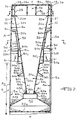
- Figs 1 and 2 show an upright-type vacuum cleaning appliance 10 which is adapted for use in both the upright mode and the cylinder mode, the upright mode being illustrated.
- the functioning of the appliance 10 will now be described with reference to this upright mode.
- the cleaning appliance 10 includes a cleaning head 11 connected to a casing 12 which supports a motor fan unit (not shown) which is mounted behind conventional floor engaging brushes (not shown) and inside wheels (not shown). Exterior wheels 13 are mounted behind the casing 12.
- An outer cyclone or container 15 is mounted on the casing 12.
- the outer cyclone 15 is preferably made of clear plastic so that a person can see the outer cyclone 15 fill with dirt.
- the outer cyclone 15 has a circular cross-section along a longitudinal axis a-a and is preferably cylindrical, or else it can be outwardly tapering if space and dimensions permit.
- a skirt 16 is mounted on the outer cyclone 15 and extends to the casing 12.
- the outer cyclone 15 has a bottom wall formed by the frusto-conical section 40d of a receiver 40 that tapers downwardly and outwardly from the axis a-a, and a cylindrical inner surface 15a ( Figure 3) which extends from the bottom wall 40d of the receiver 40.
- a circular cross-sectioned airflow directing head 18 Supported on the outer cyclone 15 is a circular cross-sectioned airflow directing head 18 which is sealed to the upper edge of the outer cyclone 15 by means of a flexible inverted L-shaped seal 19 and an annular lip member 15c of the outer cyclone 15 ( Figure 2).
- an inner cyclone 20 Positioned radially inwardly of the outer cyclone 15 and head 18 is an inner cyclone 20.
- the outer cyclone 15 and the inner cyclone 20 are preferably relatively long and slender along the longitudinal axis a-a.
- the casing 12 is provided with a vertical extension 12a ( Figure 3) which forms a rigid socket for slideably receiving the lower end of a tubular pipe or wand 21.
- the pipe 21 includes a grip 22.
- the hand grip 22 enables the appliance 10 to be used as an upright-type machine.
- the pipe 21 is slideably removed from the extension 12a, the pipe 21 is then used as a cleaner head at the end of a flexible hose (not shown) thus converting the appliance 10 into a cylinder type machine.
- the conversion of the appliance 10 from one mode of operation to the other and vice versa is described more fully in our US Patent No. 4,377,882.
- Tube 29 extends from a dirty air inlet passage (not shown) in casing 12 to a tube 30 mounted on the outside wall 18a of the head 18 which forms the upper half of dirty air inlet passage 27, ( Figure 3).
- Tube 30 communicates through the upper part of the outside wall 18a of the head 18 through an inlet passage 31 so as to effect tangential entry and set up a swirling, cyclonic flow of air in a passage 32 of the head 18 leading to the outer cyclone 15.
- a conduit 18c which forms a clean air exhaust passage 33 from the inner cyclone 20.
- Exhaust passage 33 is in communication through head 18 with the upper half of the clean air exhaust passage 28 ( Figure 3) which is formed by a tube 34 mounted on the outside wall 18a of the head 18.
- the lower part of tube 34 leads to a rigid lower exhaust tube (not shown) which is mounted on the outside wall 15b of the outer cyclone 15.
- the lower exhaust tube (not shown) forms the lower half of the clean air exhaust outlet (not shown) in the casing 12 which cools the motor fan unit and exhausts at casing vents 12b below the skirt 16 as shown in Figure 1.
- the inner cyclone 20 is a frusto-conical body, extending downwardly and tapering inwardly towards the axis a-a, and is connected to an inlet scroll 36.
- the inner cyclone 20 comprises an inner wall 20a leading to a cone opening 20b and an outer surface 20c of the inner wall 20a.
- the inlet scroll 36 comprises a horizontal web 37 ( Figure 6) which extends from the upper edge 20d of the inner cyclone 20 to the inner surface 18d of the head 18.
- a sleeve 38 extends through the majority of the length of the inlet scroll 36 from the junction of the upper end surface 20d of the inner cyclone 20 and web 37 to the bottom side of plate 18b.
- a second horizontal web 39 extends from the upper end 38a of sleeve 38 to the junction where the inside wall 18d of head 18 meets plate 18b.
- a portion 38b ( Figure 4) of sleeve 38 extends, in the form of a spiral, from the junction of the upper end surface 20d of the inner cyclone 20 and the web 37 to the inside wall 18d of the head 18 thereby competing the inlet scroll 36 and providing a tangential entry to the inner cyclone 20 in order to be capable of setting up a swirling cyclonic flow of air.
- the cone opening 20b of the inner cyclone 20 is connected to the dirt collecting receiver 40 for collecting dirt from the inner cyclone 20.
- the lower end of the outer surface 20c of the inner cyclone 20 engages a circular plate 40a which meets a frusto-conical member 40b that tapers downwardly and outwardly from the axis a-a.
- the lower edge of frusto-conical member 40b meets the upper edge of a short cylindrical member 40c of the receiver 40.
- a flexible annular sealing member 41 Interposed between the inner cyclone 20 and the plate 40a of receiver 40.
- the frusto-conical section 40d which forms the bottom wall of the outer cyclone 15 and which extends downwardly and outwardly from the axis a-a to the inner surface 15a of outer cyclone 15 about 1.1 inches (2.7 cm) above the bottom wall 40e of receiver 40.
- the maximum diameter of the frusto-conical section 40d is preferably at least three times the diameter of the cone opening 20b, as described in US Patent No. 4,826,515.
- Figure 2a shows an alternative preferred version of the connection between the cone opening 20b of the inner cyclone 20 and a receiver 140 which is similar to receiver 40.
- the receiver 140 has a frusto-conical section 140a secured directly to the cone opening 20b through inverted U-shaped annular seal 141a.
- the frusto-concial section 140a tapers downwardly and outwardly from the axis b-b to an inner annular ring member 140b.
- a bottom plate 140c circular in plan view, extends to and meets a first frusto-conical member 140d which tapers upwardly and outwardly from axis b-b.
- the upper edge of the first frusto-conical 140d meets a first cylindrical member 140e which extends to and meets a second frusto-conical member 140f.
- the second frusto-conical member 140f tapers upwardly and outwardly from the axis b-b to a second cylindrical member 140g.
- the second cylindrical member 140g seals against the inner surface 16a of skirt 16 through annular ring seal 141b.
- the receiver 140 is completed by annular ring seal 141c which is disposed between the inner annular ring member 140b and the second cylindrical member 140g thereby sealing the outer cyclone 15 from the receiver 140.
- a combined shroud and disc unit 50 is mounted on the inner cyclone 20 intermediate the passage 32 leading to inlet scroll 36 and the cone opening 20b as particularly shown in Figure 2.
- the upper part of the unit 50 is tapered with wall 50a preferably parallel to the outer surface 20c of the inner cyclone 20 and forming passage 52.
- the wall 50a ends in a flange 50b which limits and encloses the inlet passage 32 to the inner cyclone 20.
- Cylindrical section 50c depends from the lower end of wall 50a to an annular web 50d.
- a plurality of openings 50e (partially shown in Figure 5), located that are in and around the circumference of the cylindrical section 50c, serve as an outlet from the outer cyclone 15 to passage 51 leading to passage 52.
- Web 50d extends between the cylindrical section 50c and the outer surface 20c of the inner cyclone 20 where it meets conical member 50f leading to a cylindrical section 50g.
- a disc 50h which can be conically shaped with a large downwardly tapered portion 50i facing the bottom wall 40d of the outer cyclone 15.
- the disc 50h can have a downward inclination forming an angle of between about 97-1/2° to 110° with the axis a-a or 7-1/2° to 20° with a line perpendicular to the axis a-a (not shown).
- Figure 2B shows another version of the combined shroud and disc unit 150 that fits over the outer surface 20c of the inner cyclone 20, inside the head 18 and the outer cyclone 15, similar to the shroud and disc unit 50 shown in Figure 2.
- the upper part of the unit 150 is formed by a frusto-conical section 150a that tapers upwardly and outwardly from the axis e-e to a flange 150b.
- a cylindrical section 150c depends from the lower end of the frusto-conical section 150a to an annular web 150d.
- Web 150d extends between the cylindrical member 150c toward the axis e-e and contacts the outer surface 20c of the inner cyclone 20. Web 150d meets a conical member 150f that together with web 150d forms a seal between the inner cyclone 20 and the lower end of the combined shroud and disc unit 150. Extending from the junction of the cylindrical member 150c and the web 150d is a disc 150h which can be conically shaped with a large downward inclination forming an angle of between about 97-1/2° to 110° with the axis e-e or 7-1/2° to 20° with a line perpendicular to the axis e-e. The disc 150h can also be perpendicular to the axis e-e (not shown).
- FIG 2C shows still another version of the shroud unit 250 that fits over the outer surface 20c of the inner cyclone 20, inside of head 18 and the outer cyclone 15, similar to the shroud and disc unit 50 shown in Figure 2.
- the upper part of the unit 250 is formed by a frusto-conical section 250a that tapers upwardly and outwardly from the axis f-f to a flange 250b.
- a cylindrical section 250c depends from the lower end of the frusto-conical section 250a to an annular web 250d.
- Web 250d extends between the cylindrical section 250c toward the axis f-f where it contacts the outer surface 20c of the inner cyclone 20 similar to web 150d of the shroud and disc unit shown in Figure 2B.
- Web 250d meets a conical member 250f that, together with web 250d, forms a seal between the inner cyclone 20 and the lower end of the combined shroud and disc unit 250.
- the shroud unit 250 does not have a disc to help to keep large dirt particles and fibrous matter in the outer cyclone 15 as is characteristic of the shroud and disc unit 50 in Figure 2 and the shroud and disc unit 150 in Figure 2B.
- the fan unit in casing 12 pulls air into dirty air inlet passage 27 through tubes 29 and 30 and into inlet passage 31 leading to the outer cyclone 15.
- the air cyclones down and around the inner surface 15a and bottom wall 40d of outer cyclone 15, over the outside of walls 40c, 40b and 40a of the receiver 40 and up the outer surface 20c of the inner cyclone 20, then over the disc 50h, through openings 50e and up passages 51 and 52 defined by the shroud 50 and the outer surface 20c of the inner cyclone 20.
- the air then moves into passage 32 before entering the inlet scroll 36 leading to the inner cyclone 20 wherein the air cyclones down the inner wall 20a to the cone opening 20b before moving upward to the exhaust passage 33 formed by conduit 18c.
- the air finally moves to the clean air exhaust passage 28 defined by tube 34 and a lower exhaust tube (not shown) adjacent the outside wall 15b of the outer cyclone 15 before being exhausted to the atmosphere or to the motor fan unit in the casing 12 to assist with cooling.
- the dirt collects on the bottom wall 40d of the outer cyclone 15 and on the bottom wall 40e of the receiver 40 as shown in Figure 2. Finer dirt collects primarily in the receiver 40.
- the outer cyclone 15 and receiver 40 (not shown) or receiver 140 are removable from the head 18 for emptying by releasing a spring catch 55 housed within the skirt 16.
- the catch 55 comprises a central spring arm member 55a that attaches at its proximal end 55b to the bottom surface 140h of the bottom plate 140c of the receiver 140 through mounting bracket 140i.
- the distal end 55c of the spring arm 55a is formed into a first inverted U-shaped member 55d.
- the spring arm 55a and a proximal leg 55e of the first inverted U-shaped member 55d form a U-shaped junction 55f that secures in a mating locking member 12c mounted on the casing 12.
- a distal leg 55g of the first inverted U-shaped member 55d acts as a finger grip that protrudes out from underneath the skirt 16 adjacent the casing 12.
- a second inverted U-shaped guide member 140j is mounted on the bottom surface 140h of the bottom plate 140c of the receiver 140 spaced apart from mounting bracket 140i and adjacent the apex of the first inverted U-shaped member 55d.
- the second inverted U-shaped member 140j serves as a guide for an arrow tab 55h extending from the first inverted U-shaped member 55d of the catch 55 which helps to secure the receiver 140 and outer cyclone 15 to the head 18 and the inner cyclone 20 when the vacuum cleaning apparatus 10 is being used.
- the outer cyclone 15 and the receiver 140 can then be emptied and replaced into the vacuum cleaning apparatus 10 by fitting annular lip member 15c of the outer cyclone inside the flexible inverted L-shaped seal 19 and by fitting annular seal 141a around the cone opening 20b of the inner cyclone 20.
- the operator then pushes the outer cyclone 15 and receiver 140 towards the pipe 21 until the junction 55f of catch 55 locks into locking member 12c of casing 12 and arrow tab 55h secures into U-shaped member 140j.
- Figure 7 shows a tank type vacuum cleaning apparatus 110, which comprises an outer cyclone 111 around an inner cyclone 112, a dirt collection receiver 113 and a motor driven fan unit 114.
- the inner and outer cyclones 111 and 112 have circular cross-sections with respect to a longitudinal axis c-c.
- the outer cyclone 111 has a base 111a and a cylindrical inner surface 111b which extends from the outer periphery of the base 111a.
- a circular cross-sectioned flange 111c extends radially outwardly from the upper end part of the outside wall 111d of the outer cyclone 111 and serves as one-half of a seal for the outer cyclone 111.
- a removable cover 115 with hemispherical outer surface 115a fits over the top of the outer cyclone 111.
- the lower edge of the outer surface 115a of cover 115 has an annular rim 115b with a depending lip 115c which serves as a hand grip for removing the cover 115 from the outer cyclone 111.
- Extending inwardly from rim 115b toward the axis a-a is a horizontal support web 115d which meets the upper edge of a right-angled cross-sectioned protrusion 115e.
- An annular gasket 116 is mounted intermediate the protrusion 115e and the rim 115b on web 115d so as to be in contact with the circular cross-sectioned flange 111c.
- the gasket 116 serves to seal the cover 115 to the outer cyclone 111 while the apparatus 110 is in operation.
- the lower edge of the protrusion 115e meets the top edge of a frusto-conical section 115f which tapers radially inwardly and downwardly toward the axis c-c.
- An annular ring member 115g depends from the distal end of the conical section 115f and has openings 115h for bolts 117. Openings 115i are provided on the hemispherical outer surface 115a which serve as an exhaust port for the motor fan unit 114.
- a cylindrical dirty air inlet passage 118 communicates through the upper part of the outside wall 111d of the outer cyclone 111.
- Flanged section 118b of inlet passage 118, adjacent the outside wall 111d of the outer cyclone 111, has openings 119 for bolts 120 to secure the inlet passage 118 to the outside wall 111d of the outer cyclone 111.
- Inlet passage 118 leads to a dirty air inlet passage 121.
- inlet passage 121 communicates through the upper part of the outside wall 111d of the outer cyclone 111 so as to make a tangential entry and to set up a swirling, cyclonic flow of air in the outer cyclone 111, the exact position of the inlet passage 121 around the circumference of the outer cyclone 111 is not critical.
- a plate 124, circular in plan view, with dependent tube 125 centered around the axis c-c is positioned above the inner cyclone 112.
- the dependent tube 125 extends downwardly along axis c-c from the plate 124 substantially coaxially with the inner cyclone 112.
- the motor driven fan unit 114 is located on the plate 124 and is arranged so as to draw air from the inner cyclone 112 through dependent tube 125.
- Extending from the top side 124a of the plate 124 is annular ring member 124b which is outside and adjacent the depending ring member 115g.
- Annular ring 124b has openings 126, centered on the axis d-d coinciding with the openings 115h in the depending ring member 115g, which enable bolts 117 to secure the cover 115 to the plate 124.
- the inner cyclone 112 has a frusto-conical body extending radially downwardly and inwardly towards the axis c-c and a dependent inlet scroll 127.
- the inner cyclone 112 comprises a frusto-conical inner surface 112a leading to a cone opening 112b and an outside wall 112c.
- the inlet scroll 127 comprises the sleeve 123 which depends from the plate 124 to a horizontal annular web 128 ( Figures 7 and 8).
- the web 128 extends between the upper end 112d of the frusto-conical body and the lower end part of sleeve 123.
- a second dependent sleeve 129 extends between the cover 124 and the junction of the upper end 112d of the frusto-conical body and the web 128.
- the second sleeve 129 is located radially inwardly of the tubular sleeve 123 and through the majority of its length sleeve 129 extends from the upper end 112d of the frusto-conical body where the upper end 112d joins the inner periphery of the web 128.
- a portion 130 of the second sleeve 129 extends, in the form of a spiral, from the junction of the upper end 112d of the frusto-conical body and the web 128 to the tubular sleeve 123 thereby completing the inlet scroll 127 and providing a tangential entry to the inner cyclone 112 in order to be capable of setting up a swirling cyclonic flow of air.
- Figure 8A shows another version of the inlet scroll 127 wherein two diametrically opposed sections 130a and 130b extend from the junction of the upper end 112d of the frusto-conical body and the web 128 to the tubular sleeve 123.
- the inner cyclone 112 is provided with two opposed tangential entry points which are capable of setting up a swirling, cyclonic flow of air.
- the inlet scroll 127 can be completed by any number of sections 130 spiralling radially outwardly from the sleeve 129 to the tubular sleeve 123 as long as the sections 130 create at least one tangential entry point to the inner cyclone 112.
- a shroud 131 which comprises a tubular ring 132 that depends from the junction of the tubular sleeve 123 and the web 128.
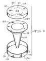
- the ring 132 of shroud 131 is totally perforated with a plurality of openings 133 (partially shown in Figure 9) that serve as an air outlet from the outer cyclone 11 to scroll 127 leading into the inner cyclone 112.
- the tubular ring 132 lies parallel to and spaced from the inner surface 111b of the outer cyclone 111.
- the shroud 131 is completed by a web 134 that extends between the lower end portion of ring 132 and the outside wall 112c of the inner cyclone 112, in particular a cylindrical support member 135 that depends from the outside wall 112c of the inner cyclone 112 and which, together with the upper surface 134a of the web 134, forms a right-angled closure from the outer cyclone 111 at an intermediate seal 136.
- the dirt collection receiver 113 for the inner cyclone 112 comprises a cylindrical portion 113a which meets the upper edge of a frusto-conical section 113b extending downwardly and outwardly from the axis c-c to the base 111a of outer cyclone 111.
- Adjacent and radially inwardly of frusto-conical section 113b is an annular ring member 111e of the outer cyclone 111 which extends beyond the upper edge of frusto-conical section 113b adjacent the inside wall 113c of the receiver 113, thus forming a seal between the receiver 113 and the outer cyclone 111.
- the cylindrical portion 113a lies intermediate the inner surface 111b of the outer cyclone 111 and the outside wall 112c of the inner cyclone 112 and is below the web 134 of the shroud 131.
- the receiver 113 is completed by a rubber seal 137 that extends from the top of the cylindrical portion 113a to the outside wall 112c of the inner cyclone 112 adjacent the web 134.
- cylindrical portion 113a can meet and seal against the web 134 of the shroud 131.
- the circumference of the cylindrical section 50c of shroud and disc unit 50 in Figure 2 was 13.6 inches (34.5 cm), the diameter was 4.3 inches (10.9 cm), and the height was 2.6 inches (6.6 cm). Where there were approximately 58 holes per row, a combination lying in the range of 32 to 38 rows of holes (8 to 10 holes/cm 2 ) of 2.2 mm diameter was found to be best for the cylindrical section 50c of the shroud and disc unit 50 of the cleaning apparatus 10 shown in Figures 1 and 2. Also, the circumference of the ring 132 of the shroud 131 of the tank type vacuum cleaning apparatus 110 shown in Figure 7 was 15.5 inches (64.8 cm), the diameter was 8.2 inches (20.8 cm), and the height was 2.5 inches (6.4 cm).
- the distance range between the cylindrical section 50c of the shroud and disc unit 50 and the inner surface 15a of the outer cyclone 15 is preferably from 0.59 inches to 1.18 inches (1.5 cm to 3.0 cm).
- the distance range between the ring 132 of the shroud 131 and the inner surface 111b of the outer cyclone 111 is preferably from 0.75 inches to 1.26 inches (1.9 cm to 3.2 cm).
- fluff will bridge between the disc 50b and the inner surface 15a of the outer cyclone 15.
- fluff attaches to the cylindrical section 50c and blocks the openings 50e. The exact distance is dependent on the diameter of the outer cyclone and the inner cyclone of the respective vacuum cleaning apparatus 10 and 110.
Abstract
Description
- The present invention relates to an improved shroud for a dual cyclonic cleaning apparatus. In particular, the present invention relates to a shroud which has a perforated section that is parallel with and spaced from the inside surface of the outer cyclone or container and which allows air to pass into a frusto-conically shaped inner cyclone without plugging the inlet openings to the inner cyclone within the apparatus.
- Cyclonic vacuum cleaning apparatus are shown in our US Patents Nos. 4,573,236; 4,593,429; 4,571,772; 4,643,748; 4,826,515; 4,853,011 and 4,853,008. Our US Patent No. 4,853,008 describes dual cyclonic cleaning apparatus wherein a combined disc and shroud unit is mounted on the outside of the inner cyclone in order to retain dirt in the outer cyclone. The shroud has a perforated lower section adjacent and above the disc which is parallel to the conical outside surface of the cyclone. The perforated section acts as an air inlet to the inner cyclone while the disc retains large dirt particles and fibrous matter in the outer cyclone. The combined disc and shroud work well; however, there was a need for an improved design which would prevent the shroud perforations from being filled with dirt before the outer cyclone was full of separated dirt.
- It is therefore an object of the present invention to provide improved cleaning apparatus wherein the shroud is designed to substantially reduce the tendancy for dirt particles and fibrous matter to obstruct the shroud openings leading to the inner cyclone air inlet. This and other objects will become increasingly apparent to those skilled in the art and by reference to the drawings.
- The invention provides shroud means for use in cleaning apparatus as set out in claim 1. The invention further provides cleaning apparatus as set out in
claim 18. Further advantageous features of the invention are set out in the dependent claims. - It is unexpected that the perforated section could be arranged directly facing the parallel inside wall of the container and have a relatively close spacing of 0.6 inches to 1.4 inches (1.5 cm to 3.6 cm) with respect to the inside wall and still be so effective in dirt separation. For upright vacuum cleaners as shown in Figures 1 and 2, the preferred diameter of the cylindrical section of the wall of the shroud and the diameter of the inside surface of the container is about 4.3 inches and 6.4 inches (10.9 and 16.3 cm), respectively. For tank type vacuum cleaners as shown in Figure 7, the diameter of the cylindrical section of the wall of the shroud and the diameter of the inside surface of the container is about 8.2 inches and 10.6 inches (20.8 cm and 26.9 cm), respectively.
- It was found that as low a pressure drop as possible through the shroud is preferred. This means that a large number of openings, preferably round, should be provided in the perforated section of the shroud.
- Embodiments of the invention will now be described with reference to the accompanying drawings, wherein:
- Figure 1 is a left side perspective view of a preferred upright type vacuum cleaning appliance according to the present invention, particularly showing an outer cyclone surrounding the combined shroud and disc unit mounted on the outside of an inner cyclone;
- Figure 2 is a partial front cross-sectional view along line 2-2 of Figure 1 showing the shroud and disc unit positioned between the inner cyclone and the outer cyclone;
- Figure 2A is a partial front cross-sectional view along a plane perpendicular to line 2-2 of Figure 1 showing the spring catch for removing the outer cyclone and receiver from the inner cyclone;
- Figure 2B shows a first alternative version of the shroud and disc unit;
- Figure 2C shows a second alternative version of the shroud;
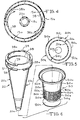
- Figure 3 is a plan cross-sectional view along line 3-3 of Figure 2 showing the dirty air inlet passage, the clean air exhaust passage and the intermediate handle mounted on the outside of the outer cyclone;
- Figure 4 is a plan cross-sectional view along line 4-4 of Figure 2 showing the tangential air inlet into the inner cyclone;
- Figure 5 is a plan cross-sectional view along line 5-5 of Figure 2 showing the perforated opening through the shroud member;
- Figure 6 is an exploded perspective view showing the positioning of the inner cyclone inside the shroud and disc unit;
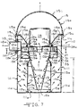
- Figure 7 is a front cross-sectional view of preferred tank-type cleaning apparatus of the present invention and particularly showing an outer cyclone, an inner cyclone, a dirt collection receiver, and an inlet scroll and associated shroud for the inner cyclone;
- Figure 8 is a plan cross-sectional view along line 7-7 of Figure 7 showing the inlet passage to the outer cyclone with a spiral member for inlet into the inner cyclone;
- Figure 8A is an alternative plan cross-sectional view similar to that shown in Figure 8 showing the inlet scroll having two spiral members rather than one;
- Figure 9 is an isometric, exploded view of the inner cyclone, inlet scroll, and the ring with openings; and
- Figure 10 is a graph showing area of opening versus pressure drop across a cylindrical section of the shroud and disc unit.
- Figs 1 and 2 show an upright-type
vacuum cleaning appliance 10 which is adapted for use in both the upright mode and the cylinder mode, the upright mode being illustrated. The functioning of theappliance 10 will now be described with reference to this upright mode. Thecleaning appliance 10 includes acleaning head 11 connected to acasing 12 which supports a motor fan unit (not shown) which is mounted behind conventional floor engaging brushes (not shown) and inside wheels (not shown).Exterior wheels 13 are mounted behind thecasing 12. - An outer cyclone or
container 15 is mounted on thecasing 12. Theouter cyclone 15 is preferably made of clear plastic so that a person can see theouter cyclone 15 fill with dirt. Theouter cyclone 15 has a circular cross-section along a longitudinal axis a-a and is preferably cylindrical, or else it can be outwardly tapering if space and dimensions permit. Askirt 16 is mounted on theouter cyclone 15 and extends to thecasing 12. Theouter cyclone 15 has a bottom wall formed by the frusto-conical section 40d of areceiver 40 that tapers downwardly and outwardly from the axis a-a, and a cylindricalinner surface 15a (Figure 3) which extends from thebottom wall 40d of thereceiver 40. Supported on theouter cyclone 15 is a circular cross-sectionedairflow directing head 18 which is sealed to the upper edge of theouter cyclone 15 by means of a flexible inverted L-shaped seal 19 and anannular lip member 15c of the outer cyclone 15 (Figure 2). Positioned radially inwardly of theouter cyclone 15 andhead 18 is aninner cyclone 20. Theouter cyclone 15 and theinner cyclone 20 are preferably relatively long and slender along the longitudinal axis a-a. - The
casing 12 is provided with avertical extension 12a (Figure 3) which forms a rigid socket for slideably receiving the lower end of a tubular pipe orwand 21. Thepipe 21 includes a grip 22. When thepipe 21 is fitted in theextension 12a, the hand grip 22 enables theappliance 10 to be used as an upright-type machine. In contrast, when thepipe 21 is slideably removed from theextension 12a, thepipe 21 is then used as a cleaner head at the end of a flexible hose (not shown) thus converting theappliance 10 into a cylinder type machine. The conversion of theappliance 10 from one mode of operation to the other and vice versa is described more fully in our US Patent No. 4,377,882. Positioned adjacent the outside wall 15b of theouter cyclone 15 and mounting theoutside wall 18a of thehead 18 on opposed sides ofpipe 21 are spaced apart dirty air inlet and cleanair exhaust passages air inlet passage 27 is formed by arigid tube 29 adjacent the outside wall 15b of theouter cyclone 15, as shown in Figure 1. Tube 29 extends from a dirty air inlet passage (not shown) incasing 12 to atube 30 mounted on theoutside wall 18a of thehead 18 which forms the upper half of dirtyair inlet passage 27, (Figure 3). Tube 30 communicates through the upper part of theoutside wall 18a of thehead 18 through aninlet passage 31 so as to effect tangential entry and set up a swirling, cyclonic flow of air in apassage 32 of thehead 18 leading to theouter cyclone 15. - As shown in Figure 2, depending from the circular upper plate 18b of
head 18 is a conduit 18c which forms a cleanair exhaust passage 33 from theinner cyclone 20.Exhaust passage 33 is in communication throughhead 18 with the upper half of the clean air exhaust passage 28 (Figure 3) which is formed by atube 34 mounted on theoutside wall 18a of thehead 18. The lower part oftube 34 leads to a rigid lower exhaust tube (not shown) which is mounted on the outside wall 15b of theouter cyclone 15. The lower exhaust tube (not shown) forms the lower half of the clean air exhaust outlet (not shown) in thecasing 12 which cools the motor fan unit and exhausts at casing vents 12b below theskirt 16 as shown in Figure 1. - The
inner cyclone 20 is a frusto-conical body, extending downwardly and tapering inwardly towards the axis a-a, and is connected to aninlet scroll 36. Theinner cyclone 20 comprises aninner wall 20a leading to a cone opening 20b and anouter surface 20c of theinner wall 20a. Theinlet scroll 36 comprises a horizontal web 37 (Figure 6) which extends from theupper edge 20d of theinner cyclone 20 to theinner surface 18d of thehead 18. Asleeve 38 extends through the majority of the length of the inlet scroll 36 from the junction of theupper end surface 20d of theinner cyclone 20 andweb 37 to the bottom side of plate 18b. A secondhorizontal web 39 extends from theupper end 38a ofsleeve 38 to the junction where theinside wall 18d ofhead 18 meets plate 18b. Aportion 38b (Figure 4) ofsleeve 38 extends, in the form of a spiral, from the junction of theupper end surface 20d of theinner cyclone 20 and theweb 37 to theinside wall 18d of thehead 18 thereby competing theinlet scroll 36 and providing a tangential entry to theinner cyclone 20 in order to be capable of setting up a swirling cyclonic flow of air. - The cone opening 20b of the
inner cyclone 20 is connected to thedirt collecting receiver 40 for collecting dirt from theinner cyclone 20. The lower end of theouter surface 20c of theinner cyclone 20 engages acircular plate 40a which meets a frusto-conical member 40b that tapers downwardly and outwardly from the axis a-a. The lower edge of frusto-conical member 40b meets the upper edge of a shortcylindrical member 40c of thereceiver 40. Interposed between theinner cyclone 20 and theplate 40a ofreceiver 40 is a flexibleannular sealing member 41. Depending from the bottom edge of thecylindrical member 40c is the frusto-conical section 40d which forms the bottom wall of theouter cyclone 15 and which extends downwardly and outwardly from the axis a-a to theinner surface 15a ofouter cyclone 15 about 1.1 inches (2.7 cm) above thebottom wall 40e ofreceiver 40. The maximum diameter of the frusto-conical section 40d is preferably at least three times the diameter of the cone opening 20b, as described in US Patent No. 4,826,515. - Figure 2a shows an alternative preferred version of the connection between the cone opening 20b of the
inner cyclone 20 and areceiver 140 which is similar toreceiver 40. Thereceiver 140 has a frusto-conical section 140a secured directly to the cone opening 20b through inverted U-shapedannular seal 141a. The frusto-concial section 140a tapers downwardly and outwardly from the axis b-b to an inner annular ring member 140b. Abottom plate 140c, circular in plan view, extends to and meets a first frusto-conical member 140d which tapers upwardly and outwardly from axis b-b. The upper edge of the first frusto-conical 140d meets a firstcylindrical member 140e which extends to and meets a second frusto-conical member 140f. The second frusto-conical member 140f tapers upwardly and outwardly from the axis b-b to a secondcylindrical member 140g. The secondcylindrical member 140g seals against the inner surface 16a ofskirt 16 through annular ring seal 141b. Thereceiver 140 is completed byannular ring seal 141c which is disposed between the inner annular ring member 140b and the secondcylindrical member 140g thereby sealing theouter cyclone 15 from thereceiver 140. - A combined shroud and
disc unit 50 is mounted on theinner cyclone 20 intermediate thepassage 32 leading toinlet scroll 36 and the cone opening 20b as particularly shown in Figure 2. The upper part of theunit 50 is tapered withwall 50a preferably parallel to theouter surface 20c of theinner cyclone 20 and formingpassage 52. Thewall 50a ends in aflange 50b which limits and encloses theinlet passage 32 to theinner cyclone 20.Cylindrical section 50c depends from the lower end ofwall 50a to anannular web 50d. A plurality ofopenings 50e (partially shown in Figure 5), located that are in and around the circumference of thecylindrical section 50c, serve as an outlet from theouter cyclone 15 topassage 51 leading topassage 52.Web 50d extends between thecylindrical section 50c and theouter surface 20c of theinner cyclone 20 where it meetsconical member 50f leading to acylindrical section 50g. Depending from thecylindrical section 50g is adisc 50h which can be conically shaped with a large downwardly tapered portion 50i facing thebottom wall 40d of theouter cyclone 15. Thedisc 50h can have a downward inclination forming an angle of between about 97-1/2° to 110° with the axis a-a or 7-1/2° to 20° with a line perpendicular to the axis a-a (not shown). - Figure 2B shows another version of the combined shroud and
disc unit 150 that fits over theouter surface 20c of theinner cyclone 20, inside thehead 18 and theouter cyclone 15, similar to the shroud anddisc unit 50 shown in Figure 2. The upper part of theunit 150 is formed by a frusto-conical section 150a that tapers upwardly and outwardly from the axis e-e to a flange 150b. Acylindrical section 150c depends from the lower end of the frusto-conical section 150a to anannular web 150d. A plurality ofopenings 150e, located in and around the circumference of thecylindrical section 150c, serve as an outlet from theouter cyclone 15.Web 150d extends between thecylindrical member 150c toward the axis e-e and contacts theouter surface 20c of theinner cyclone 20.Web 150d meets aconical member 150f that together withweb 150d forms a seal between theinner cyclone 20 and the lower end of the combined shroud anddisc unit 150. Extending from the junction of thecylindrical member 150c and theweb 150d is adisc 150h which can be conically shaped with a large downward inclination forming an angle of between about 97-1/2° to 110° with the axis e-e or 7-1/2° to 20° with a line perpendicular to the axis e-e. Thedisc 150h can also be perpendicular to the axis e-e (not shown). - Figure 2C shows still another version of the
shroud unit 250 that fits over theouter surface 20c of theinner cyclone 20, inside ofhead 18 and theouter cyclone 15, similar to the shroud anddisc unit 50 shown in Figure 2. The upper part of theunit 250 is formed by a frusto-conical section 250a that tapers upwardly and outwardly from the axis f-f to a flange 250b. Acylindrical section 250c depends from the lower end of the frusto-conical section 250a to anannular web 250d. A plurality ofopenings 250e located in and around the circumference of thesection 250c, serve as an outlet from theouter cyclone 15.Web 250d extends between thecylindrical section 250c toward the axis f-f where it contacts theouter surface 20c of theinner cyclone 20 similar toweb 150d of the shroud and disc unit shown in Figure 2B.Web 250d meets aconical member 250f that, together withweb 250d, forms a seal between theinner cyclone 20 and the lower end of the combined shroud anddisc unit 250. Theshroud unit 250 does not have a disc to help to keep large dirt particles and fibrous matter in theouter cyclone 15 as is characteristic of the shroud anddisc unit 50 in Figure 2 and the shroud anddisc unit 150 in Figure 2B. - In operation of the preferred version of the upright-type
vacuum cleaning apparatus 10 as shown in Figure 2, the fan unit in casing 12 pulls air into dirtyair inlet passage 27 throughtubes inlet passage 31 leading to theouter cyclone 15. The air cyclones down and around theinner surface 15a andbottom wall 40d ofouter cyclone 15, over the outside ofwalls receiver 40 and up theouter surface 20c of theinner cyclone 20, then over thedisc 50h, throughopenings 50e and uppassages shroud 50 and theouter surface 20c of theinner cyclone 20. The air then moves intopassage 32 before entering theinlet scroll 36 leading to theinner cyclone 20 wherein the air cyclones down theinner wall 20a to the cone opening 20b before moving upward to theexhaust passage 33 formed by conduit 18c. The air finally moves to the cleanair exhaust passage 28 defined bytube 34 and a lower exhaust tube (not shown) adjacent the outside wall 15b of theouter cyclone 15 before being exhausted to the atmosphere or to the motor fan unit in thecasing 12 to assist with cooling. The dirt collects on thebottom wall 40d of theouter cyclone 15 and on thebottom wall 40e of thereceiver 40 as shown in Figure 2. Finer dirt collects primarily in thereceiver 40. - It was surprising that the
openings 50e in thecylindrical section 50c (Figure 2) could be positioned closely adjacent theinner surface 15a of theouter cyclone 15. During testing, it had been thought that thecylindrical section 50c should be as distant as possible from the dirt swirling around theinner surface 15a of theouter cyclone 15. It had been felt that a large distance between thecylindrical section 50c and theinner surface 15a of theouter cyclone 15 would make it less likely that dirt, fluff or fibrous material would become caught up in the airflow exiting theouter cyclone 15 through theopenings 50e incylindrical section 50c. However, with thecylindrical section 50c set as far away as possible from theinner surface 15a of theouter cyclone 15, fluff and fibrous material became trapped on theouter surface 50k of thecylindrical section 50c. Surprisingly, it was found that, by positioning thecylindrical section 50c closely adjacent theinner surface 15a of the outer cyclone, theouter surface 50k of thecylindrical section 50c did not attract fibrous material and that dirt did not pass directly from the airflow circulating around theinner surface 15a of theouter cyclone 15 to theopenings 50e incylindrical member 50c. In fact, theouter surface 50k of thecylindrical member 50c was apparently being wiped clean by the airflow circulating around theinner surface 15a of theouter cyclone 15. With this construction, the dirt can accumulate to a relatively high level in the outer cyclone 15 (about level L) with good separation of the dirt. - As shown in Figure 2A, the
outer cyclone 15 and receiver 40 (not shown) orreceiver 140 are removable from thehead 18 for emptying by releasing aspring catch 55 housed within theskirt 16. Thecatch 55 comprises a centralspring arm member 55a that attaches at its proximal end 55b to thebottom surface 140h of thebottom plate 140c of thereceiver 140 through mounting bracket 140i. Thedistal end 55c of thespring arm 55a is formed into a first invertedU-shaped member 55d. Thespring arm 55a and a proximal leg 55e of the first invertedU-shaped member 55d form aU-shaped junction 55f that secures in amating locking member 12c mounted on thecasing 12. A distal leg 55g of the first invertedU-shaped member 55d acts as a finger grip that protrudes out from underneath theskirt 16 adjacent thecasing 12. A second invertedU-shaped guide member 140j is mounted on thebottom surface 140h of thebottom plate 140c of thereceiver 140 spaced apart from mounting bracket 140i and adjacent the apex of the first invertedU-shaped member 55d. The second invertedU-shaped member 140j serves as a guide for anarrow tab 55h extending from the first invertedU-shaped member 55d of thecatch 55 which helps to secure thereceiver 140 andouter cyclone 15 to thehead 18 and theinner cyclone 20 when thevacuum cleaning apparatus 10 is being used. - When the
outer cyclone 15 and thereceiver 140 become full of accumulated dirt, the operator raises the distal leg 55g of the first invertedU-shaped member 55d which releases thejunction 55f ofcatch 55 from the lockingmember 12c and thearrow tab 55h from the second invertedU-shaped member 140j. The operator then pulls theouter cyclone 15,receiver 140 andskirt 16 away from the handle 21 (Figure 1) which causes theannular lip member 15c of theouter cyclone 15 to release from thehead 18 at the flexible inverted L-shapedseal 19 and thereceiver 140 to release from theinner cyclone 20 at theannular seal 141a, thereby exposing the rigid tube, the rigid lower exhaust tube (not shown) and the bottom part of theintermediate pipe 21. Theouter cyclone 15 and thereceiver 140 can then be emptied and replaced into thevacuum cleaning apparatus 10 by fittingannular lip member 15c of the outer cyclone inside the flexible inverted L-shapedseal 19 and by fittingannular seal 141a around the cone opening 20b of theinner cyclone 20. The operator then pushes theouter cyclone 15 andreceiver 140 towards thepipe 21 until thejunction 55f ofcatch 55 locks into lockingmember 12c ofcasing 12 andarrow tab 55h secures intoU-shaped member 140j. - Figure 7 shows a tank type
vacuum cleaning apparatus 110, which comprises anouter cyclone 111 around aninner cyclone 112, adirt collection receiver 113 and a motor drivenfan unit 114. The inner andouter cyclones outer cyclone 111 has a base 111a and a cylindrical inner surface 111b which extends from the outer periphery of the base 111a. A circularcross-sectioned flange 111c extends radially outwardly from the upper end part of theoutside wall 111d of theouter cyclone 111 and serves as one-half of a seal for theouter cyclone 111. - A
removable cover 115 with hemisphericalouter surface 115a fits over the top of theouter cyclone 111. The lower edge of theouter surface 115a ofcover 115 has an annular rim 115b with a dependinglip 115c which serves as a hand grip for removing thecover 115 from theouter cyclone 111. Extending inwardly from rim 115b toward the axis a-a is ahorizontal support web 115d which meets the upper edge of a right-angledcross-sectioned protrusion 115e. Anannular gasket 116 is mounted intermediate theprotrusion 115e and the rim 115b onweb 115d so as to be in contact with the circularcross-sectioned flange 111c. Thegasket 116 serves to seal thecover 115 to theouter cyclone 111 while theapparatus 110 is in operation. The lower edge of theprotrusion 115e meets the top edge of a frusto-conical section 115f which tapers radially inwardly and downwardly toward the axis c-c. Anannular ring member 115g depends from the distal end of theconical section 115f and hasopenings 115h for bolts 117. Openings 115i are provided on the hemisphericalouter surface 115a which serve as an exhaust port for themotor fan unit 114. - A cylindrical dirty
air inlet passage 118 communicates through the upper part of theoutside wall 111d of theouter cyclone 111. Theend part 118a of the dirtyair inlet passage 118, remote from theouter cyclone 111, is joined by a flexible tube (not shown) to a cleaner head (not shown) for contacting a dirty surface. Flanged section 118b ofinlet passage 118, adjacent theoutside wall 111d of theouter cyclone 111, hasopenings 119 forbolts 120 to secure theinlet passage 118 to theoutside wall 111d of theouter cyclone 111.Inlet passage 118 leads to a dirtyair inlet passage 121. As long asinlet passage 121 communicates through the upper part of theoutside wall 111d of theouter cyclone 111 so as to make a tangential entry and to set up a swirling, cyclonic flow of air in theouter cyclone 111, the exact position of theinlet passage 121 around the circumference of theouter cyclone 111 is not critical. - A
plate 124, circular in plan view, withdependent tube 125 centered around the axis c-c is positioned above theinner cyclone 112. Thedependent tube 125 extends downwardly along axis c-c from theplate 124 substantially coaxially with theinner cyclone 112. The motor drivenfan unit 114 is located on theplate 124 and is arranged so as to draw air from theinner cyclone 112 throughdependent tube 125. Extending from the top side 124a of theplate 124 is annular ring member 124b which is outside and adjacent the dependingring member 115g. Annular ring 124b hasopenings 126, centered on the axis d-d coinciding with theopenings 115h in the dependingring member 115g, which enable bolts 117 to secure thecover 115 to theplate 124. - The
inner cyclone 112 has a frusto-conical body extending radially downwardly and inwardly towards the axis c-c and adependent inlet scroll 127. Theinner cyclone 112 comprises a frusto-conical inner surface 112a leading to a cone opening 112b and anoutside wall 112c. Theinlet scroll 127 comprises thesleeve 123 which depends from theplate 124 to a horizontal annular web 128 (Figures 7 and 8). Theweb 128 extends between the upper end 112d of the frusto-conical body and the lower end part ofsleeve 123. A seconddependent sleeve 129 extends between thecover 124 and the junction of the upper end 112d of the frusto-conical body and theweb 128. Thesecond sleeve 129 is located radially inwardly of thetubular sleeve 123 and through the majority of itslength sleeve 129 extends from the upper end 112d of the frusto-conical body where the upper end 112d joins the inner periphery of theweb 128. As shown in Figure 8, aportion 130 of thesecond sleeve 129 extends, in the form of a spiral, from the junction of the upper end 112d of the frusto-conical body and theweb 128 to thetubular sleeve 123 thereby completing theinlet scroll 127 and providing a tangential entry to theinner cyclone 112 in order to be capable of setting up a swirling cyclonic flow of air. - Figure 8A shows another version of the
inlet scroll 127 wherein two diametricallyopposed sections 130a and 130b extend from the junction of the upper end 112d of the frusto-conical body and theweb 128 to thetubular sleeve 123. In this manner, theinner cyclone 112 is provided with two opposed tangential entry points which are capable of setting up a swirling, cyclonic flow of air. It should be noted that theinlet scroll 127 can be completed by any number ofsections 130 spiralling radially outwardly from thesleeve 129 to thetubular sleeve 123 as long as thesections 130 create at least one tangential entry point to theinner cyclone 112. - Depending from the
scroll 127 and spaced from theoutside wall 112c of theinner cyclone 112 is ashroud 131 which comprises atubular ring 132 that depends from the junction of thetubular sleeve 123 and theweb 128. Thering 132 ofshroud 131 is totally perforated with a plurality of openings 133 (partially shown in Figure 9) that serve as an air outlet from theouter cyclone 11 to scroll 127 leading into theinner cyclone 112. Thetubular ring 132 lies parallel to and spaced from the inner surface 111b of theouter cyclone 111. Theshroud 131 is completed by aweb 134 that extends between the lower end portion ofring 132 and theoutside wall 112c of theinner cyclone 112, in particular acylindrical support member 135 that depends from theoutside wall 112c of theinner cyclone 112 and which, together with the upper surface 134a of theweb 134, forms a right-angled closure from theouter cyclone 111 at anintermediate seal 136. - The
dirt collection receiver 113 for theinner cyclone 112 comprises acylindrical portion 113a which meets the upper edge of a frusto-conical section 113b extending downwardly and outwardly from the axis c-c to the base 111a ofouter cyclone 111. Adjacent and radially inwardly of frusto-conical section 113b is an annular ring member 111e of theouter cyclone 111 which extends beyond the upper edge of frusto-conical section 113b adjacent theinside wall 113c of thereceiver 113, thus forming a seal between thereceiver 113 and theouter cyclone 111. Thecylindrical portion 113a lies intermediate the inner surface 111b of theouter cyclone 111 and theoutside wall 112c of theinner cyclone 112 and is below theweb 134 of theshroud 131. Thereceiver 113 is completed by arubber seal 137 that extends from the top of thecylindrical portion 113a to theoutside wall 112c of theinner cyclone 112 adjacent theweb 134. In another embodiment (not shown),cylindrical portion 113a can meet and seal against theweb 134 of theshroud 131. - The following are parameters for the preferred vacuum cleaner.
- In the preferred version of the upright-type
vacuum cleaning apparatus 10 as shown in Figure 2, and the preferred version of the tank-typevacuum cleaning apparatus 110 as shown in Figure 7, there should be approximately the number and size of openings orholes 50e in thecylindrical section 50c of the shroud anddisc unit 50 andopenings 133 in thetubular ring 132 ofshroud 131 to position the pressure differential through thecylindrical section 50c and the pressure differential through thering 132 ofshroud 131 as far along from the pressure increase rise of the graph (Figure 10) as possible. It was found that, if there was a high differential pressure through thecylindrical section 50c and through thering 132 ofshroud 131, large dirt particles that collect in theouter cyclones outer cyclones openings 50e incylindrical section 50c and theopenings 133 in thetubular ring 132 ofshroud 131 where they will then enter theinner cyclones cylindrical section 50c of the shroud anddisc unit 50 and theopenings 133 in thetubular ring 132 ofshroud 131. This result is undesirable because the large dirt particles will not separate out in theinner cyclones exhaust passage 33 of theinner cyclone 20 and through thedependent tube 125 exhausting from theinner cyclone 112, where the large dirt particles will then be drawn into themotor fan units motor fan units - The above discussion is also applicable for the pressure between the
inside surface 150j and the outside surface 150k of thecylindrical section 150c (Figure 2B) and for the pressure between the inside surface 250j and the outside surface 250k of thecylindrical section 250c (Figure 2C). - The circumference of the
cylindrical section 50c of shroud anddisc unit 50 in Figure 2 was 13.6 inches (34.5 cm), the diameter was 4.3 inches (10.9 cm), and the height was 2.6 inches (6.6 cm). Where there were approximately 58 holes per row, a combination lying in the range of 32 to 38 rows of holes (8 to 10 holes/cm2) of 2.2 mm diameter was found to be best for thecylindrical section 50c of the shroud anddisc unit 50 of thecleaning apparatus 10 shown in Figures 1 and 2. Also, the circumference of thering 132 of theshroud 131 of the tank typevacuum cleaning apparatus 110 shown in Figure 7 was 15.5 inches (64.8 cm), the diameter was 8.2 inches (20.8 cm), and the height was 2.5 inches (6.4 cm). Where there were approximately 208 holes per row, a combination lying in the range of 34 to 38 rows of holes (17 to 19 holes/cm2) of 2.2 mm diameter was found to be best for thering 132 of theshroud 131. A 2.2 mm diameter hole is sufficiently small to block the passage of particles of a greater size than would be successfully separated by theinner cyclone 20 of Figure 2 and theinner cyclone 112 of Figure 7. - It was believed that the greater the total area of
holes cylindrical section 50c and thering 132 of theshroud 131 would be better at not attracting fluff. Also, a lower pressure at eachopening 50e of the upright typevacuum cleaning apparatus 10 and at each opening 133 of thering 132 of theshroud 131 of the tank typevacuum cleaning apparatus 110 would make it easier for fine dirt to gather at and maybe block rather than be drawn through theopenings respective vacuum cleaners - It was found that better results were obtained when material at least 2 mm thick was used for the
shrouds - For the upright
type vacuum cleaner 10 in Figures 1 and 2, the distance range between thecylindrical section 50c of the shroud anddisc unit 50 and theinner surface 15a of theouter cyclone 15 is preferably from 0.59 inches to 1.18 inches (1.5 cm to 3.0 cm). For the tank typevacuum cleaning apparatus 110 in Figure 7, the distance range between thering 132 of theshroud 131 and the inner surface 111b of theouter cyclone 111 is preferably from 0.75 inches to 1.26 inches (1.9 cm to 3.2 cm). However, if the distance between thecylindrical section 50c of the shroud anddisc unit 50 is too close, fluff will bridge between thedisc 50b and theinner surface 15a of theouter cyclone 15. Alternatively, if the distance is too great, fluff attaches to thecylindrical section 50c and blocks theopenings 50e. The exact distance is dependent on the diameter of the outer cyclone and the inner cyclone of the respectivevacuum cleaning apparatus - It is intended that the foregoing description be only illustrative of the present invention and that the present invention be limited only to the hereinafter appended claims.
Claims (18)
- Shroud means (50,150,250) for use in cleaning apparatus (10), the cleaning apparatus (10) including: a container (15) having a circular cross-section and comprising a bottom (40d) and a sidewall extending to and meeting the bottom (40d), the sidewall having an interior surface (15a), a dirty air inlet (27) which is oriented for supplying dirt laden air into the container (15) tangentially to the interior surface (15a) of the sidewall, and an air outlet from the container (15); a circular cross-sectioned cyclone (20) having a longitudinal axis and mounted inside the container (15), the cyclone (20) comprising a cyclone air inlet (36) at an upper end of the cyclone (20) in air communication with the air outlet of the container, an interior dirt rotational surface (20a) of frusto-conical shape for receiving an air flow from the air inlet (36) and for maintaining its velocity to a cone opening (20b) smaller in diameter than the diameter of the upper end of the cyclone (20), the air inlet (36) being oriented for supplying air tangentially to the interior dirt rotational surface (20a), an outer surface (20c) of frusto-conical shape, and a cyclone air outlet (33) communicating with the interior of the cyclone (20) adjacent the upper end of the cyclone (20); a dirt collecting receiver (40) extending from the the cone opening (20b); and means for generating an airflow which passes sequentially through the dirty air inlet (27), the container (15), the cyclone air inlet (36), the cyclone (20), the dirt receiver (40) and the cyclone air outlet (33), the airflow rotating around the frusto-conical interior surface (20a) of the cyclone (20) and depositing dirt in the receiver (40); the shroud means (50,150,250) being mountable on and around the outer surface (20c) of the cyclone (20) and, when in use, having opposed ends spaced in the direction of the longitudinal axis of the cyclone (20) and providing an air passageway from the container (15) to the air inlet (36) of the cyclone (20), one of the ends of the shroud means (50,150,250) being sealed against the outer surface (20c) of the cyclone (20), characterised in that a portion of the shroud (50,150,250) has a cylindrical perforated section (50c,150c,250c) having a density of perforations (50e,150e,250e) with a range 8 to 19 holes/cm2, the perforated section (50c,150c,250c) being spaced from the interior wall (15a) of the sidewall of container (15).
- Shroud means as claimed in claim 1, wherein the density of perforations is within the range 8 to 10 holes/cm2.
- Shroud means as claimed in claim 2, wherein the cylindrical perforated section (50c,150c,250c) has a diameter of substantially 10.9cm.
- Shroud means as claimed in claim 1, wherein the density of perforations is within the range 17 to 19 holes/cm2.
- Shroud means as claimed in claim 2 or 4, wherein the cylindrical perforated section (50c,150c,250c) has a diameter of substantially 20.8cm.
- Shroud means as claimed in any one of the preceding claims, wherein the end of the shroud means (50,150,250) which is sealed against the outer surface (20c) of the cyclone (20) comprises a web section (50d,150d,250d) which abuts directly against the outer surface (20c).
- Shroud means as claimed in any one of the preceding claims, wherein the perforations (50e,150e,250e) through the perforated section (50c,150c,250c) are circular and are provided around a circumferential extent of the perforated section (50c,150c,250c) of the shroud means (50,150,250).
- Shroud means as claimed in claim 7, wherein the circular perforations have a diameter of 2.2mm.
- Shroud means as claimed in any one of the preceding claims, wherein, in use, the perforated section (50c,150c,250c) of the shroud means (50,150,250) is located between 0.59 inches and 1.38 inches (1.5 cm and 3.5 cm) from the inside wall (15a) of the container.
- Shroud means as claimed in any one of the preceding claims, wherein the shroud means (50,150,250) has a flanged section (50b,150b,250b) above the cylindrical section (50c,150c,250c), the flanged section (50,150,250) being locatable around the longitudinal axis at an end of the cyclone (20) adjacent the air inlet (36) and in closely spaced relationship to the outside (20c) of the cyclone (20) so as to provide, in use, a chamber (32) leading to the air inlet (36).
- Shroud means as claimed in any one of the preceding claims, wherein disc means (50h,150h,250h) are provided at a lower longitudinal extent of the shroud means (50,150,250), the disc means (50h,150h,250h) being locatable around the axis of the cyclone (20) with a space between the interior surface (15a) of the sidewall of the container (15) and the disc means (50h,150h,250h) for passage of air therebetween, such that, in use, the disc means (50h,150h,250h) aid in dirt removal in the container (15) by preventing some of the dirt from flowing to the air inlet (36) of the cyclone (20).
- Shroud means as claimed in claim 11, wherein the shroud means (50,150,250) and the disc means (50h,150h,250h) form an integral unit slidable over the outer surface (20c) of the cyclone (20) such that the cone opening (20b) protrudes below and out of the unit.
- Shroud means as claimed in claim 11 or 12 when dependent on claim 6, wherein a lower section (50f,150f,250f) of the shroud means (50,150,250) depending from a radius of the web section (50d,150d,250d) of the shroud means (50,150,250) supports the disc means (50h,150h,250h) and is locatable in sealed relationship with the outside wall (20c) of the cyclone (20) so that, in use, the airflow in the container (15) must travel over the disc means (50h,150h,250h) and past an outside surface of a lower section of the shroud means (50,150,250) before passing through the openings (50e,150e,250e) in the cylindrical section (50c,150c,250c) leading to the air inlet (36) of the cyclone (20).
- Shroud means as claimed in any one of claims 11 to 13, wherein the disc means (50h,150h,250h) are circular in cross-section.
- Shroud means as claimed in any one of claims 11 to 14, wherein the disc means (50h,150h,250h) have a conical shape around the shroud means (50,150,250) such that, in use, a larger portion of the conical shape faces towards the bottom (40d) of the container (15).
- Shroud means as claimed in claim 15, wherein the conical shape, when viewed as a cross-section of the shroud means (50,150,250) and disc means (50h,150h,250h) through the longitudinal axis, is downwardly inclined at an angle of between 7-1/2° and 20° with respect to a line perpendicular to the longitudinal axis of the cyclone (20).
- Shroud means as claimed in any one of claims 11 to 16, wherein, in use, the disc means (50h,150h,250h) are positioned at about one third of the distance between the cone opening (20b) and the air inlet (36) of the cyclone (20).
- Cleaning apparatus including shroud means (50,150,250) according to any one of the preceding claims.
Applications Claiming Priority (3)
| Application Number | Priority Date | Filing Date | Title |
|---|---|---|---|
| US07/621,375 US5078761A (en) | 1990-07-06 | 1990-12-03 | Shroud |
| US621375 | 1990-12-03 | ||
| EP91311229A EP0489565B1 (en) | 1990-12-03 | 1991-12-03 | Shroud and cyclonic cleaning apparatus incorporating same |
Related Parent Applications (1)
| Application Number | Title | Priority Date | Filing Date |
|---|---|---|---|
| EP91311229.8 Division | 1991-12-03 |
Publications (3)
| Publication Number | Publication Date |
|---|---|
| EP0636338A2 EP0636338A2 (en) | 1995-02-01 |
| EP0636338A3 EP0636338A3 (en) | 1995-05-17 |
| EP0636338B1 true EP0636338B1 (en) | 1997-06-11 |
Family
ID=24489897
Family Applications (2)
| Application Number | Title | Priority Date | Filing Date |
|---|---|---|---|
| EP94117238A Expired - Lifetime EP0636338B1 (en) | 1990-12-03 | 1991-12-03 | Shroud and cyclonic cleaning apparatus incorporating same |
| EP91311229A Expired - Lifetime EP0489565B1 (en) | 1990-12-03 | 1991-12-03 | Shroud and cyclonic cleaning apparatus incorporating same |
Family Applications After (1)
| Application Number | Title | Priority Date | Filing Date |
|---|---|---|---|
| EP91311229A Expired - Lifetime EP0489565B1 (en) | 1990-12-03 | 1991-12-03 | Shroud and cyclonic cleaning apparatus incorporating same |
Country Status (10)
| Country | Link |
|---|---|
| US (1) | US5078761A (en) |
| EP (2) | EP0636338B1 (en) |
| JP (1) | JPH0685753B2 (en) |
| AT (2) | ATE154216T1 (en) |
| AU (1) | AU637272B2 (en) |
| CA (1) | CA2056161C (en) |
| DE (2) | DE69126546T2 (en) |
| ES (1) | ES2105467T3 (en) |
| HK (2) | HK1000956A1 (en) |
| SG (1) | SG43964A1 (en) |
Families Citing this family (228)
| Publication number | Priority date | Publication date | Assignee | Title |
|---|---|---|---|---|
| US5145499A (en) * | 1990-09-21 | 1992-09-08 | Notetry Limited | Disposable bin for cyclonic vacuum |
| US5267371A (en) * | 1992-02-19 | 1993-12-07 | Iona Appliances Inc. | Cyclonic back-pack vacuum cleaner |
| AU669539B2 (en) * | 1992-06-24 | 1996-06-13 | Dyson Technology Limited | Vacuum cleaner |
| US5558697A (en) * | 1992-12-08 | 1996-09-24 | Notetry Limited | Dual cyclonic vacuum cleaner |
| MY112609A (en) * | 1994-12-21 | 2001-07-31 | Dyson Technology Ltd | Improved dust separation apparatus |
| GB2296452A (en) * | 1994-12-28 | 1996-07-03 | Notetry Ltd | Shroud for cyclone separator |
| GB2296879A (en) * | 1995-01-10 | 1996-07-17 | Notetry Ltd | Dust separation apparatus |
| US5893938A (en) * | 1995-12-20 | 1999-04-13 | Notetry Limited | Dust separation apparatus |
| GB2315231A (en) | 1996-07-15 | 1998-01-28 | Notetry Ltd | Apparatus for Separating Particles |
| SE509696C2 (en) | 1996-09-04 | 1999-02-22 | Electrolux Ab | Separation device for a vacuum cleaner |
| EP0836827B1 (en) | 1996-10-21 | 2000-11-29 | CANDY S.p.A. | A household vacuum cleaner |
| SE508525C2 (en) * | 1997-02-13 | 1998-10-12 | Electrolux Ab | Cyclone separator for a vacuum cleaner |
| ES2171875T3 (en) * | 1997-06-20 | 2002-09-16 | Candy Spa | DOMESTIC VACUUM CLEANER WITH AXIAL CYCLONE. |
| GB9817073D0 (en) | 1997-11-04 | 1998-10-07 | Bhr Group Ltd | Phase separator |
| GB9817074D0 (en) * | 1997-11-04 | 1998-10-07 | Bhr Group Ltd | Fluid treatments |
| GB9817071D0 (en) | 1997-11-04 | 1998-10-07 | Bhr Group Ltd | Cyclone separator |
| US5908493A (en) * | 1997-11-17 | 1999-06-01 | Krymsky; Mark D. | Filtering system for cleaning air |
| US6003196A (en) * | 1998-01-09 | 1999-12-21 | Royal Appliance Mfg. Co. | Upright vacuum cleaner with cyclonic airflow |
| US6735817B2 (en) * | 1998-01-09 | 2004-05-18 | Royal Appliance Mfg. Co. | Upright vacuum cleaner with cyclonic air flow |
| EP1052924B1 (en) | 1998-01-09 | 2010-03-24 | Royal Appliance Manufacturing Co. | Upright vacuum cleaner with cyclonic airflow |
| US6070291A (en) | 1998-01-09 | 2000-06-06 | Royal Appliance Mfg. Co. | Upright vacuum cleaner with cyclonic air flow |
| US6183527B1 (en) | 1998-02-02 | 2001-02-06 | Black & Decker Inc. | Dust collector with work surface |
| US6171356B1 (en) * | 1998-04-28 | 2001-01-09 | Frank Twerdun | Cyclonic vacuum generator apparatus and method |
| SE9901252L (en) | 1999-04-08 | 2000-02-28 | Electrolux Ab | Drainage system for a cyclone vacuum cleaner |
| US6168716B1 (en) | 1998-08-19 | 2001-01-02 | G.B.D. Corp. | Cyclone separator having a variable transverse profile |
| US6277278B1 (en) | 1998-08-19 | 2001-08-21 | G.B.D. Corp. | Cyclone separator having a variable longitudinal profile |
| US6129775A (en) | 1998-08-19 | 2000-10-10 | G.B.D. Corp. | Terminal insert for a cyclone separator |
| US6312594B1 (en) | 1998-08-19 | 2001-11-06 | G.B.D. Corp. | Insert for a cyclone separator |
| GB9823418D0 (en) | 1998-10-26 | 1998-12-23 | Notetry Ltd | Cyclonic seperating apparatus |
| GB2344777A (en) * | 1998-12-18 | 2000-06-21 | Notetry Ltd | Horizontal cyclonic separator with single fin or baffle |
| GB2344745B (en) * | 1998-12-18 | 2002-06-05 | Notetry Ltd | Vacuum cleaner |
| US6782585B1 (en) * | 1999-01-08 | 2004-08-31 | Fantom Technologies Inc. | Upright vacuum cleaner with cyclonic air flow |
| US6141826A (en) * | 1999-01-08 | 2000-11-07 | G.B.D. Corp. | Center air feed for cyclonic separator |
| US6238451B1 (en) * | 1999-01-08 | 2001-05-29 | Fantom Technologies Inc. | Vacuum cleaner |
| US6334234B1 (en) * | 1999-01-08 | 2002-01-01 | Fantom Technologies Inc. | Cleaner head for a vacuum cleaner |
| US6344064B1 (en) | 1999-01-29 | 2002-02-05 | Fantom Technologies Inc. | Method and apparatus of particle transfer in multi-stage particle separators |
| JP3476066B2 (en) * | 1999-07-19 | 2003-12-10 | シャープ株式会社 | Electric vacuum cleaner |
| US6440197B1 (en) | 1999-07-27 | 2002-08-27 | G.B.D. Corp. | Apparatus and method separating particles from a cyclonic fluid flow including an apertured particle separation member within a cyclonic flow region |
| US6228260B1 (en) | 1999-07-27 | 2001-05-08 | G. B. D. Corp. | Apparatus for separating particles from a cyclonic fluid flow |
| EP1200196B1 (en) * | 1999-07-27 | 2005-06-15 | G.B.D. Corporation | Apparatus and method for separating particles from a cyclonic fluid flow |
| US6221134B1 (en) | 1999-07-27 | 2001-04-24 | G.B.D. Corp. | Apparatus and method for separating particles from a cyclonic fluid flow |
| US6251296B1 (en) | 1999-07-27 | 2001-06-26 | G.B.D. Corp. | Apparatus and method for separating particles from a cyclonic fluid flow |
| US6231645B1 (en) | 1999-07-27 | 2001-05-15 | G.B.D. Corp. | Apparatus and method for separating particles from a cyclonic fluid flow utilizing a movable access member associated with a cyclonic separator |
| US6228151B1 (en) | 1999-08-18 | 2001-05-08 | G.B.D. Corp. | Apparatus and method for separating particles from a cyclonic fluid flow |
| US6269518B1 (en) | 1999-12-08 | 2001-08-07 | Shell Electric Mfg. (Holdings) Co. Ltd. | Bagless vacuum cleaner |
| US6484350B2 (en) | 1999-12-08 | 2002-11-26 | Shell Electric Mfg. (Holdings) Co. Ltd. | Bagless canister vacuum cleaner |
| US6558453B2 (en) * | 2000-01-14 | 2003-05-06 | White Consolidated Industries, Inc. | Bagless dustcup |
| US6910245B2 (en) * | 2000-01-14 | 2005-06-28 | White Consolidated Industries, Inc. | Upright vacuum cleaner with cyclonic air path |
| GB2362341B (en) | 2000-05-16 | 2002-12-04 | Samsung Kwangju Electronics Co | Upright-type vacuum cleaner |
| AU754573B2 (en) * | 2000-06-16 | 2002-11-21 | Samsung Gwangju Electronics Co., Ltd. | Upright-type vacuum cleaner having a cyclone dust collecting apparatus |
| GB2363744B (en) * | 2000-06-24 | 2002-11-13 | Samsung Kwangju Electronics Co | Upright type vacuum cleaner having a cyclone-type dust collector |
| GB2374033B (en) * | 2000-06-24 | 2003-04-09 | Samsung Kwangju Electronics Co | Upright type vacuum cleaner having a cyclone-type dust collector |
| WO2002003846A1 (en) * | 2000-07-06 | 2002-01-17 | John Herbert North | Improved air-particle separator |
| GB2399308B (en) * | 2000-07-06 | 2005-02-09 | John Herbert North | Improved air/particle separator |
| GB2367774B (en) * | 2000-07-06 | 2004-04-28 | John Herbert North | Improved air/particle separator |
| KR100398684B1 (en) * | 2000-11-27 | 2003-09-19 | 삼성광주전자 주식회사 | Cyclone dust-collecting apparatus for vacuum cleaner |
| KR100437369B1 (en) | 2001-01-10 | 2004-06-25 | 삼성광주전자 주식회사 | Cyclone dust-collecting apparatus for Vacuum Cleaner |
| CA2342673A1 (en) * | 2001-03-30 | 2002-09-30 | Gbd Corp. | Air cleaner with coarse filter |
| KR100412584B1 (en) * | 2001-06-02 | 2003-12-31 | 삼성광주전자 주식회사 | Grille assembly for a cyclone-type dust collecting apparatus for a vacuum cleaner |
| US6613129B2 (en) | 2001-06-22 | 2003-09-02 | Euro-Pro Corporation | Cyclone and dust filter vacuum cleaner |
| JP3569915B2 (en) * | 2002-01-16 | 2004-09-29 | ツインバード工業株式会社 | Double cyclone vacuum cleaner |
| US6829804B2 (en) | 2002-03-26 | 2004-12-14 | White Consolidated, Ltd. | Filtration arrangement of a vacuum cleaner |
| CN1279869C (en) * | 2002-04-28 | 2006-10-18 | 苏州金莱克清洁器具有限公司 | Speed reducing centrifugal duster for cleaner |
| KR100437107B1 (en) * | 2002-05-31 | 2004-06-23 | 삼성광주전자 주식회사 | Vacuum cleaner |
| US7152275B2 (en) * | 2002-07-18 | 2006-12-26 | Panasonic Corporation Of North America | Dirt container for cyclonic vacuum cleaner |
| US6951045B2 (en) | 2002-08-20 | 2005-10-04 | Royal Appliance Mfg. Co. | Vacuum cleaner having hose detachable at nozzle |
| US6887290B2 (en) * | 2002-09-25 | 2005-05-03 | Federal Signal Corporation | Debris separation and filtration systems |
| GB0228148D0 (en) * | 2002-12-03 | 2003-01-08 | Techtronic Ind Co Ltd | Dust separator and collector arrangement for suction cleaner |
| GB0228153D0 (en) * | 2002-12-03 | 2003-01-08 | Techtronic Ind Co Ltd | Suction cleaners |
| GB0228152D0 (en) * | 2002-12-03 | 2003-01-08 | Techtronic Ind Co Ltd | Cyclonic separators for suction cleaners |
| WO2004052166A1 (en) * | 2002-12-06 | 2004-06-24 | Techtronic Industries Company Limited | Head for a suction cleaner |
| JP4195982B2 (en) * | 2003-03-26 | 2008-12-17 | パナソニック株式会社 | Vacuum cleaner |
| KR100471142B1 (en) | 2003-05-21 | 2005-03-10 | 삼성광주전자 주식회사 | Cyclone dust collecting device and vacuum cleaner having the same |
| US7544224B2 (en) * | 2003-08-05 | 2009-06-09 | Electrolux Home Care Products, Inc. | Cyclonic vacuum cleaner |
| US7293324B2 (en) * | 2003-09-19 | 2007-11-13 | Techtronic Industries Co., Ltd. | Vacuum cleaner with level control |
| JP4152291B2 (en) | 2003-09-30 | 2008-09-17 | 三洋電機株式会社 | Vacuum cleaner |
| GB2407784A (en) * | 2003-11-08 | 2005-05-11 | Dyson Ltd | Separating apparatus |
| KR100592098B1 (en) * | 2004-02-11 | 2006-06-22 | 삼성광주전자 주식회사 | Cyclone Dust Collector of Vacuum Cleaner |
| GB2416482B (en) * | 2004-07-22 | 2007-12-05 | Techtronic Ind Co Ltd | Hose assembly for suction cleaner |
| GB2417674B (en) * | 2004-09-02 | 2007-12-19 | Techtronic Ind Co Ltd | Suction cleaners |
| KR100622548B1 (en) * | 2004-12-02 | 2006-09-19 | 삼성광주전자 주식회사 | A Dust-Separating Apparatus For A Vacuum Cleaner |
| GB2422090B (en) * | 2005-01-12 | 2008-07-02 | Techtronic Ind Co Ltd | Head for a suction cleaner |
| GB2423037A (en) * | 2005-02-15 | 2006-08-16 | Techtronic Ind Co Ltd | Cyclonic separator for suction cleaner |
| US7410516B2 (en) * | 2005-03-17 | 2008-08-12 | Royal Appliance Mfg. Co. | Twin cyclone vacuum cleaner |
| GB2425246B (en) * | 2005-04-21 | 2008-07-23 | Vax Ltd | Dust separator/collector assembly for suction cleaner |
| WO2006125354A1 (en) * | 2005-05-27 | 2006-11-30 | Wang, Yuedan | A dust cup in a centrifugal cleaner with fall |
| US8291545B2 (en) | 2005-06-24 | 2012-10-23 | Royal Appliance Mfg., Co. | Twin cyclone vacuum cleaner |
| US8438700B2 (en) * | 2005-12-22 | 2013-05-14 | Techtronic Floor Care Technology Limited | Dual stage cyclone vacuum cleaner |
| CN100405965C (en) * | 2005-12-23 | 2008-07-30 | 苏州金莱克家用电器有限公司 | Diffusion type dust collection unit of dust cleaner |
| US7811345B2 (en) * | 2006-03-10 | 2010-10-12 | G.B.D. Corp. | Vacuum cleaner with a removable cyclone array |
| JP4320663B2 (en) * | 2006-03-17 | 2009-08-26 | ツインバード工業株式会社 | Cyclone vacuum cleaner |
| GB2436308A (en) * | 2006-03-23 | 2007-09-26 | Adrian Christopher Arnold | Particle separator |
| JP2007252838A (en) * | 2006-03-27 | 2007-10-04 | Sharp Corp | Vacuum cleaner |
| US20070234687A1 (en) | 2006-04-06 | 2007-10-11 | Suzhou Kingclean Floorcare Co., Ltd. | Second-stage separator device for a vacuum cleaner |
| AU2007278711A1 (en) * | 2006-07-21 | 2008-01-31 | Wang, Yuedan | The secondary cyclonic dust separating cup of vacuum cleaner |
| DE102006046328B4 (en) * | 2006-09-28 | 2008-06-19 | Miele & Cie. Kg | Device for separating dust from dust-laden air, in particular for use in a vacuum cleaner |
| US8950039B2 (en) | 2009-03-11 | 2015-02-10 | G.B.D. Corp. | Configuration of a surface cleaning apparatus |
| CA2599303A1 (en) | 2007-08-29 | 2009-02-28 | Gbd Corp. | Surface cleaning apparatus |
| CA2677526C (en) | 2006-12-12 | 2013-11-26 | G.B.D. Corp. | Convertible surface cleaning apparatus |
| US10765277B2 (en) | 2006-12-12 | 2020-09-08 | Omachron Intellectual Property Inc. | Configuration of a surface cleaning apparatus |
| US20210401246A1 (en) | 2016-04-11 | 2021-12-30 | Omachron Intellectual Property Inc. | Surface cleaning apparatus |
| US9888817B2 (en) | 2014-12-17 | 2018-02-13 | Omachron Intellectual Property Inc. | Surface cleaning apparatus |
| US9192269B2 (en) | 2006-12-15 | 2015-11-24 | Omachron Intellectual Property Inc. | Surface cleaning apparatus |
| KR100864708B1 (en) * | 2006-12-28 | 2008-10-23 | 삼성광주전자 주식회사 | a dust-separating apparatus of a vacuum cleaner |
| KR100783143B1 (en) * | 2007-02-05 | 2007-12-07 | 삼성광주전자 주식회사 | Cyclone separating apparatus for vacuum cleaner |
| KR100776402B1 (en) * | 2007-02-05 | 2007-11-16 | 삼성광주전자 주식회사 | Multi cyclone separating apparatus having filter assembly |
| KR100776403B1 (en) * | 2007-02-14 | 2007-11-16 | 삼성광주전자 주식회사 | Cyclone dust separating apparatus for vacuum cleaner |
| US11751733B2 (en) | 2007-08-29 | 2023-09-12 | Omachron Intellectual Property Inc. | Portable surface cleaning apparatus |
| JP2008043792A (en) * | 2007-10-29 | 2008-02-28 | Hitachi Appliances Inc | Vacuum cleaner |
| GB2454227B (en) * | 2007-11-01 | 2012-02-29 | Dyson Technology Ltd | Cyclonic separating apparatus |
| KR101472776B1 (en) * | 2007-11-05 | 2014-12-17 | 삼성전자주식회사 | multi cyclone dust-separating apparatus of vacuum cleaner |
| CN101939110B (en) | 2007-12-19 | 2015-01-21 | Gbd公司 | Configuration of a cyclone assembly and surface cleaning apparatus having same |
| US20090178237A1 (en) * | 2008-01-16 | 2009-07-16 | Proffitt Ii Donald E | Vacuum cleaner with spiral air guide |
| SE531908C2 (en) * | 2008-01-16 | 2009-09-08 | Electrolux Ab | Vacuum cleaner |
| USD626708S1 (en) | 2008-03-11 | 2010-11-02 | Royal Appliance Mfg. Co. | Hand vacuum |
| CN104274121B (en) * | 2008-10-22 | 2017-05-03 | 创科地板护理技术有限公司 | Handheld vacuum cleaner |
| US9226633B2 (en) | 2009-03-13 | 2016-01-05 | Omachron Intellectual Property Inc. | Surface cleaning apparatus |
| US9211044B2 (en) | 2011-03-04 | 2015-12-15 | Omachron Intellectual Property Inc. | Compact surface cleaning apparatus |
| US9138114B2 (en) | 2009-03-13 | 2015-09-22 | Omachron Intellectual Property Inc. | Surface cleaning apparatus |
| CA2967272C (en) | 2009-03-13 | 2018-01-02 | Omachron Intellectual Property Inc. | Hand vacuum cleaner |
| US9265395B2 (en) * | 2010-03-12 | 2016-02-23 | Omachron Intellectual Property Inc. | Surface cleaning apparatus |
| CA2674376A1 (en) | 2009-03-13 | 2010-09-13 | G.B.D. Corp. | Surface cleaning apparatus with different cleaning configurations |
| US9591953B2 (en) | 2009-03-13 | 2017-03-14 | Omachron Intellectual Property Inc. | Surface cleaning apparatus |
| US9198551B2 (en) | 2013-02-28 | 2015-12-01 | Omachron Intellectual Property Inc. | Surface cleaning apparatus |
| US9427122B2 (en) | 2009-03-13 | 2016-08-30 | Omachron Intellectual Property Inc. | Surface cleaning apparatus |
| US9480373B2 (en) | 2009-03-13 | 2016-11-01 | Omachron Intellectual Property Inc. | Surface cleaning apparatus |
| US8578555B2 (en) * | 2010-03-12 | 2013-11-12 | G.B.D. Corp. | Surface cleaning apparatus |
| US9433332B2 (en) | 2013-02-27 | 2016-09-06 | Omachron Intellectual Property Inc. | Surface cleaning apparatus |
| CA2674761C (en) | 2009-03-13 | 2016-10-04 | G.B.D. Corp. | Surface cleaning apparatus with different cleaning configurations |
| US11612288B2 (en) | 2009-03-13 | 2023-03-28 | Omachron Intellectual Property Inc. | Surface cleaning apparatus |
| US9392916B2 (en) | 2009-03-13 | 2016-07-19 | Omachron Intellectual Property Inc. | Surface cleaning apparatus |
| US11690489B2 (en) | 2009-03-13 | 2023-07-04 | Omachron Intellectual Property Inc. | Surface cleaning apparatus with an external dirt chamber |
| US10722086B2 (en) | 2017-07-06 | 2020-07-28 | Omachron Intellectual Property Inc. | Handheld surface cleaning apparatus |
| JP5193932B2 (en) * | 2009-04-24 | 2013-05-08 | 日立アプライアンス株式会社 | Electric vacuum cleaner |
| US8082624B2 (en) | 2009-11-10 | 2011-12-27 | Oreck Holdings Llc | Rotatable coupling for steering vacuum cleaner |
| US8418778B2 (en) | 2010-01-07 | 2013-04-16 | Black & Decker Inc. | Power screwdriver having rotary input control |
| US9266178B2 (en) | 2010-01-07 | 2016-02-23 | Black & Decker Inc. | Power tool having rotary input control |
| US9475180B2 (en) | 2010-01-07 | 2016-10-25 | Black & Decker Inc. | Power tool having rotary input control |
| US8875340B2 (en) * | 2010-03-12 | 2014-11-04 | G.B.D. Corp. | Surface cleaning apparatus with enhanced operability |
| US8640304B2 (en) * | 2010-03-12 | 2014-02-04 | G.B.D. Corp. | Cyclone construction for a surface cleaning apparatus |
| US8677554B2 (en) * | 2010-03-12 | 2014-03-25 | G.B.D. Corp. | Valve for a surface cleaning apparatus |
| US8813305B2 (en) * | 2010-03-12 | 2014-08-26 | G.B.D. Corp. | Compact surface cleaning apparatus |
| US8296900B2 (en) * | 2010-03-12 | 2012-10-30 | G.B.D. Corp. | Seal construction for a surface cleaning apparatus |
| US8875342B2 (en) * | 2010-03-12 | 2014-11-04 | G.B.D. Corp. | Bleed air valve of a surface cleaning apparatus |
| US8375508B2 (en) * | 2010-03-12 | 2013-02-19 | G.B.D. Corp. | Torque balancer for a surface cleaning head |
| US20110219567A1 (en) * | 2010-03-12 | 2011-09-15 | G.B.D. Corp. | Reconfigurable upright surface cleaning apparatus with a powered brush motor |
| US8152877B2 (en) * | 2010-03-12 | 2012-04-10 | Euro-Pro Operating Llc | Shroud for a cleaning service apparatus |
| US20110219579A1 (en) * | 2010-03-12 | 2011-09-15 | G.B.D. Corp. | Suction motor housing for an upright surface cleaning apparatus |
| AU2011295880A1 (en) * | 2010-09-01 | 2013-04-18 | Techtronic Floor Care Technology Limited | Vacuum cleaner with exhaust tube having an increasing cross-sectional area |
| GB2494366B (en) | 2011-02-18 | 2014-04-23 | Techtronic Floor Care Tech Ltd | Vacuum cleaner dirt cup |
| US8578553B2 (en) | 2011-03-04 | 2013-11-12 | G.B.D. Corp. | Sound shield for a surface cleaning apparatus |
| SE536286C2 (en) | 2011-10-06 | 2013-07-30 | Husqvarna Ab | Dust separator with constant suction power |
| EP2631035B1 (en) | 2012-02-24 | 2019-10-16 | Black & Decker Inc. | Power tool |
| JP5077494B1 (en) | 2012-02-29 | 2012-11-21 | 三菱電機株式会社 | Cyclone separation device and vacuum cleaner |
| US9814361B2 (en) | 2012-03-09 | 2017-11-14 | Sharkninja Operating Llc | Surface cleaning apparatus |
| CN104582555B (en) * | 2012-08-15 | 2017-08-25 | 三菱电机株式会社 | Cyclone separator and the electric dust collector with the cyclone separator |
| US8997310B2 (en) | 2012-10-12 | 2015-04-07 | Electrolux Home Care Products, Inc. | Vacuum cleaner cyclone with helical cyclone expansion region |
| EP2916705B1 (en) | 2012-11-09 | 2020-06-03 | Aktiebolaget Electrolux | Cyclone dust separator arrangement, cyclone dust separator and cyclone vacuum cleaner |
| US9591958B2 (en) | 2013-02-27 | 2017-03-14 | Omachron Intellectual Property Inc. | Surface cleaning apparatus |
| US9320401B2 (en) | 2013-02-27 | 2016-04-26 | Omachron Intellectual Property Inc. | Surface cleaning apparatus |
| US9027198B2 (en) | 2013-02-27 | 2015-05-12 | G.B.D. Corp. | Surface cleaning apparatus |
| US9820621B2 (en) | 2013-02-28 | 2017-11-21 | Omachron Intellectual Property Inc. | Surface cleaning apparatus |
| US20140237764A1 (en) | 2013-02-28 | 2014-08-28 | G.B.D. Corp. | Cyclone such as for use in a surface cleaning apparatus |
| US9215960B2 (en) | 2013-02-28 | 2015-12-22 | Omachron Intellectual Property Inc. | Surface cleaning apparatus |
| US9295995B2 (en) | 2013-02-28 | 2016-03-29 | Omachron Intellectual Property Inc. | Cyclone such as for use in a surface cleaning apparatus |
| US9227151B2 (en) | 2013-02-28 | 2016-01-05 | Omachron Intellectual Property Inc. | Cyclone such as for use in a surface cleaning apparatus |
| US9204773B2 (en) | 2013-03-01 | 2015-12-08 | Omachron Intellectual Property Inc. | Surface cleaning apparatus |
| US9161669B2 (en) | 2013-03-01 | 2015-10-20 | Omachron Intellectual Property Inc. | Surface cleaning apparatus |
| US9238235B2 (en) | 2013-02-28 | 2016-01-19 | Omachron Intellectual Property Inc. | Cyclone such as for use in a surface cleaning apparatus |
| US9451855B2 (en) | 2013-02-28 | 2016-09-27 | Omachron Intellectual Property Inc. | Surface cleaning apparatus |
| US9326652B2 (en) | 2013-02-28 | 2016-05-03 | Omachron Intellectual Property Inc. | Surface cleaning apparatus |
| US9427126B2 (en) | 2013-03-01 | 2016-08-30 | Omachron Intellectual Property Inc. | Surface cleaning apparatus |
| US9227201B2 (en) | 2013-02-28 | 2016-01-05 | Omachron Intellectual Property Inc. | Cyclone such as for use in a surface cleaning apparatus |
| US9314138B2 (en) | 2013-02-28 | 2016-04-19 | Omachron Intellectual Property Inc. | Surface cleaning apparatus |
| US9364127B2 (en) | 2013-02-28 | 2016-06-14 | Omachron Intellectual Property Inc. | Surface cleaning apparatus |
| US9456721B2 (en) | 2013-02-28 | 2016-10-04 | Omachron Intellectual Property Inc. | Surface cleaning apparatus |
| US9844308B2 (en) | 2014-04-08 | 2017-12-19 | Sharkninja Operating Llc | Surface cleaning apparatus |
| US9420925B2 (en) | 2014-07-18 | 2016-08-23 | Omachron Intellectual Property Inc. | Portable surface cleaning apparatus |
| US9585530B2 (en) | 2014-07-18 | 2017-03-07 | Omachron Intellectual Property Inc. | Portable surface cleaning apparatus |
| US9314139B2 (en) | 2014-07-18 | 2016-04-19 | Omachron Intellectual Property Inc. | Portable surface cleaning apparatus |
| US9451853B2 (en) | 2014-07-18 | 2016-09-27 | Omachron Intellectual Property Inc. | Portable surface cleaning apparatus |
| KR102246450B1 (en) * | 2014-10-15 | 2021-04-30 | 삼성전자주식회사 | Cleaner |
| US10251519B2 (en) | 2014-12-17 | 2019-04-09 | Omachron Intellectual Property Inc. | Surface cleaning apparatus |
| US9883781B2 (en) | 2014-12-17 | 2018-02-06 | Omachron Intellectual Property Inc. | All in the head surface cleaning apparatus |
| US10136778B2 (en) | 2014-12-17 | 2018-11-27 | Omachron Intellectual Property Inc. | Surface cleaning apparatus |
| US10022027B2 (en) | 2014-12-17 | 2018-07-17 | Omachron Intellectual Property Inc. | All in the head surface cleaning apparatus |
| US11950745B2 (en) | 2014-12-17 | 2024-04-09 | Omachron Intellectual Property Inc. | Surface cleaning apparatus |
| GB2541677B (en) | 2015-08-25 | 2018-04-18 | Dyson Technology Ltd | An upright vacuum cleaner |
| KR102560970B1 (en) * | 2016-03-31 | 2023-07-31 | 엘지전자 주식회사 | Cleaner |
| US11166607B2 (en) | 2016-03-31 | 2021-11-09 | Lg Electronics Inc. | Cleaner |
| CN113143096B (en) * | 2016-03-31 | 2023-08-18 | Lg电子株式会社 | Dust collector |
| US10258210B2 (en) | 2016-12-27 | 2019-04-16 | Omachron Intellectual Property Inc. | Multistage cyclone and surface cleaning apparatus having same |
| US10136779B2 (en) | 2016-08-29 | 2018-11-27 | Omachron Intellectual Property Inc. | Surface cleaning apparatus |
| US11478117B2 (en) | 2016-08-29 | 2022-10-25 | Omachron Intellectual Property Inc. | Surface cleaning apparatus |
| US10441125B2 (en) | 2016-08-29 | 2019-10-15 | Omachron Intellectual Property Inc. | Surface cleaning apparatus |
| US10321794B2 (en) | 2016-08-29 | 2019-06-18 | Omachron Intellectual Property Inc. | Surface cleaning apparatus |
| US10433689B2 (en) | 2016-08-29 | 2019-10-08 | Omachron Intellectual Property Inc. | Surface cleaning apparatus |
| US10413141B2 (en) | 2016-08-29 | 2019-09-17 | Omachron Intellectual Property Inc. | Surface cleaning apparatus |
| US10441124B2 (en) | 2016-08-29 | 2019-10-15 | Omachron Intellectual Property Inc. | Surface cleaning apparatus |
| US10292550B2 (en) | 2016-08-29 | 2019-05-21 | Omachron Intellectual Property Inc. | Surface cleaning apparatus |
| US9962050B2 (en) | 2016-08-29 | 2018-05-08 | Omachron Intellectual Property Inc. | Surface cleaning apparatus |
| US10405711B2 (en) | 2016-08-29 | 2019-09-10 | Omachron Intellectual Property Inc. | Surface cleaning apparatus |
| US10729295B2 (en) | 2016-08-29 | 2020-08-04 | Omachron Intellectual Property Inc. | Surface cleaning apparatus |
| US10136780B2 (en) | 2016-08-29 | 2018-11-27 | Omachron Intellectual Property Inc. | Surface cleaning apparatus |
| GB2554933B (en) * | 2016-10-14 | 2022-04-27 | Techtronic Floor Care Tech Ltd | Cyclonic separation device |
| US10271704B2 (en) | 2016-12-27 | 2019-04-30 | Omachron Intellectual Property Inc. | Multistage cyclone and surface cleaning apparatus having same |
| US10299643B2 (en) | 2016-12-27 | 2019-05-28 | Omachron Intellectual Property Inc. | Multistage cyclone and surface cleaning apparatus having same |
| US10405709B2 (en) | 2016-12-27 | 2019-09-10 | Omachron Intellectual Property Inc. | Multistage cyclone and surface cleaning apparatus having same |
| US10016106B1 (en) | 2016-12-27 | 2018-07-10 | Omachron Intellectual Property Inc. | Multistage cyclone and surface cleaning apparatus having same |
| US11285495B2 (en) | 2016-12-27 | 2022-03-29 | Omachron Intellectual Property Inc. | Multistage cyclone and surface cleaning apparatus having same |
| US10827891B2 (en) | 2016-12-27 | 2020-11-10 | Omachron Intellectual Property Inc. | Multistage cyclone and surface cleaning apparatus having same |
| US10842330B2 (en) | 2017-07-06 | 2020-11-24 | Omachron Intellectual Property Inc. | Handheld surface cleaning apparatus |
| US11766156B2 (en) | 2020-03-18 | 2023-09-26 | Omachron Intellectual Property Inc. | Surface cleaning apparatus with removable air treatment member assembly |
| US10702113B2 (en) | 2017-07-06 | 2020-07-07 | Omachron Intellectual Property Inc. | Handheld surface cleaning apparatus |
| US10537216B2 (en) | 2017-07-06 | 2020-01-21 | Omachron Intellectual Property Inc. | Handheld surface cleaning apparatus |
| US11445878B2 (en) | 2020-03-18 | 2022-09-20 | Omachron Intellectual Property Inc. | Surface cleaning apparatus with removable air treatment member assembly |
| US10631693B2 (en) | 2017-07-06 | 2020-04-28 | Omachron Intellectual Property Inc. | Handheld surface cleaning apparatus |
| US10750913B2 (en) | 2017-07-06 | 2020-08-25 | Omachron Intellectual Property Inc. | Handheld surface cleaning apparatus |
| US10506904B2 (en) | 2017-07-06 | 2019-12-17 | Omachron Intellectual Property Inc. | Handheld surface cleaning apparatus |
| US11666193B2 (en) | 2020-03-18 | 2023-06-06 | Omachron Intellectual Property Inc. | Surface cleaning apparatus with removable air treatment member assembly |
| US11730327B2 (en) | 2020-03-18 | 2023-08-22 | Omachron Intellectual Property Inc. | Surface cleaning apparatus with removable air treatment assembly |
| US11478116B2 (en) | 2018-01-15 | 2022-10-25 | Omachron Intellectual Property Inc | Surface cleaning apparatus |
| US11930987B2 (en) | 2018-04-20 | 2024-03-19 | Omachron Intellectual Property Inc. | Surface cleaning apparatus |
| US11192122B2 (en) | 2018-08-13 | 2021-12-07 | Omachron Intellectual Property Inc. | Cyclonic air treatment member and surface cleaning apparatus including the same |
| US11006799B2 (en) | 2018-08-13 | 2021-05-18 | Omachron Intellectual Property Inc. | Cyclonic air treatment member and surface cleaning apparatus including the same |
| US11013384B2 (en) | 2018-08-13 | 2021-05-25 | Omachron Intellectual Property Inc. | Cyclonic air treatment member and surface cleaning apparatus including the same |
| US11751740B2 (en) | 2019-11-18 | 2023-09-12 | Omachron Intellectual Property Inc. | Multi-inlet cyclone |
| US11246462B2 (en) | 2019-11-18 | 2022-02-15 | Omachron Intellectual Property Inc. | Multi-inlet cyclone |
Family Cites Families (8)
| Publication number | Priority date | Publication date | Assignee | Title |
|---|---|---|---|---|
| GB469539A (en) * | 1936-01-04 | 1937-07-27 | British Thomson Houston Co Ltd | Improvements in and relating to apparatus for separating dust from air |
| GB1386055A (en) * | 1972-09-22 | 1975-03-05 | Electrolux Ab | Floor-treating apparatus |
| DE3171910D1 (en) * | 1980-06-19 | 1985-09-26 | Rotork Appliances Ltd | Vacuum cleaning appliance |
| US4593429A (en) * | 1980-06-19 | 1986-06-10 | Prototypes, Ltd. | Vacuum cleaning appliance |
| US4571772A (en) * | 1982-12-27 | 1986-02-25 | Prototypes, Ltd. | Upright vacuum cleaning appliance |
| US4573236A (en) * | 1983-07-08 | 1986-03-04 | Prototypes, Ltd. | Vacuum cleaning appliances |
| US4643748A (en) * | 1986-02-24 | 1987-02-17 | Notetry Limited | Cleaning apparatus |
| US4853008A (en) * | 1988-07-27 | 1989-08-01 | Notetry Limited | Combined disc and shroud for dual cyclonic cleaning apparatus |
-
1990
- 1990-12-03 US US07/621,375 patent/US5078761A/en not_active Expired - Lifetime
-
1991
- 1991-11-25 CA CA002056161A patent/CA2056161C/en not_active Expired - Fee Related
- 1991-11-27 AU AU88194/91A patent/AU637272B2/en not_active Expired
- 1991-12-03 EP EP94117238A patent/EP0636338B1/en not_active Expired - Lifetime
- 1991-12-03 EP EP91311229A patent/EP0489565B1/en not_active Expired - Lifetime
- 1991-12-03 DE DE69126546T patent/DE69126546T2/en not_active Expired - Lifetime
- 1991-12-03 SG SG1996007692A patent/SG43964A1/en unknown
- 1991-12-03 DE DE69110424T patent/DE69110424T2/en not_active Expired - Lifetime
- 1991-12-03 AT AT94117238T patent/ATE154216T1/en not_active IP Right Cessation
- 1991-12-03 ES ES94117238T patent/ES2105467T3/en not_active Expired - Lifetime
- 1991-12-03 JP JP3357465A patent/JPH0685753B2/en not_active Expired - Lifetime
- 1991-12-03 AT AT91311229T patent/ATE123639T1/en not_active IP Right Cessation
-
1997
- 1997-12-29 HK HK97102673A patent/HK1000956A1/en not_active IP Right Cessation
- 1997-12-29 HK HK97102672A patent/HK1001469A1/en not_active IP Right Cessation
Also Published As
| Publication number | Publication date |
|---|---|
| JPH0685753B2 (en) | 1994-11-02 |
| EP0636338A2 (en) | 1995-02-01 |
| US5078761A (en) | 1992-01-07 |
| EP0636338A3 (en) | 1995-05-17 |
| ATE154216T1 (en) | 1997-06-15 |
| DE69126546T2 (en) | 1998-01-29 |
| EP0489565B1 (en) | 1995-06-14 |
| AU637272B2 (en) | 1993-05-20 |
| SG43964A1 (en) | 1997-11-14 |
| AU8819491A (en) | 1992-06-11 |
| EP0489565A1 (en) | 1992-06-10 |
| CA2056161A1 (en) | 1992-06-04 |
| ATE123639T1 (en) | 1995-06-15 |
| DE69110424T2 (en) | 1996-02-01 |
| DE69126546D1 (en) | 1997-07-17 |
| HK1001469A1 (en) | 1998-06-19 |
| CA2056161C (en) | 1996-02-13 |
| ES2105467T3 (en) | 1997-10-16 |
| DE69110424D1 (en) | 1995-07-20 |
| JPH05176871A (en) | 1993-07-20 |
| HK1000956A1 (en) | 1998-05-15 |
Similar Documents
| Publication | Publication Date | Title |
|---|---|---|
| EP0636338B1 (en) | Shroud and cyclonic cleaning apparatus incorporating same | |
| US5145499A (en) | Disposable bin for cyclonic vacuum | |
| CA1321960C (en) | Combined disc and shroud for dual cyclonic cleaning apparatus | |
| US5950274A (en) | Separation device for a vacuum cleaner | |
| EP0459783B1 (en) | Vacuum cleaner | |
| US7628832B2 (en) | Bagless dustcup | |
| AU709674B2 (en) | Apparatus for cleaning floors, carpets and the like | |
| CA1159610A (en) | Vacuum cleaning appliances | |
| US7547351B2 (en) | Multi cyclone dust collector for a vacuum cleaner | |
| US6706095B2 (en) | Cyclonic separating apparatus | |
| US6432154B2 (en) | Cyclone dust collecting apparatus for a vacuum cleaner | |
| US6991667B2 (en) | Attaching and detaching device for contaminant collecting receptacle of cyclone separator | |
| JP3442351B2 (en) | Electric vacuum cleaner | |
| US20040060146A1 (en) | Dirt collecting system for a floor care appliance | |
| MXPA00001895A (en) | Cyclonic dirt cup assembly. | |
| JP2003135335A (en) | Dust cup and vacuum cleaner | |
| KR100437365B1 (en) | A cyclone dust-collecting apparatus of vacuum cleaner | |
| KR0133762B1 (en) | Vacuum cleaner for wet-dry type | |
| KR200394919Y1 (en) | Dust collecting unit | |
| KR101196029B1 (en) | Dust collecting unit | |
| KR20060125960A (en) | Dust collecting unit | |
| MXPA98006796A (en) | Apparatus to clean floors, carpets and simi |
Legal Events
| Date | Code | Title | Description |
|---|---|---|---|
| PUAI | Public reference made under article 153(3) epc to a published international application that has entered the european phase |
Free format text: ORIGINAL CODE: 0009012 |
|
| 17P | Request for examination filed |
Effective date: 19941118 |
|
| AC | Divisional application: reference to earlier application |
Ref document number: 489565 Country of ref document: EP |
|
| AK | Designated contracting states |
Kind code of ref document: A2 Designated state(s): AT BE CH DE DK ES FR GB GR IT LI LU NL SE |
|
| PUAL | Search report despatched |
Free format text: ORIGINAL CODE: 0009013 |
|
| AK | Designated contracting states |
Kind code of ref document: A3 Designated state(s): AT BE CH DE DK ES FR GB GR IT LI LU NL SE |
|
| 17Q | First examination report despatched |
Effective date: 19960528 |
|
| GRAG | Despatch of communication of intention to grant |
Free format text: ORIGINAL CODE: EPIDOS AGRA |
|
| GRAH | Despatch of communication of intention to grant a patent |
Free format text: ORIGINAL CODE: EPIDOS IGRA |
|
| GRAH | Despatch of communication of intention to grant a patent |
Free format text: ORIGINAL CODE: EPIDOS IGRA |
|
| RAP1 | Party data changed (applicant data changed or rights of an application transferred) |
Owner name: NOTETRY LIMITED |
|
| GRAA | (expected) grant |
Free format text: ORIGINAL CODE: 0009210 |
|
| AC | Divisional application: reference to earlier application |
Ref document number: 489565 Country of ref document: EP |
|
| AK | Designated contracting states |
Kind code of ref document: B1 Designated state(s): AT BE CH DE DK ES FR GB GR IT LI LU NL SE |
|
| PG25 | Lapsed in a contracting state [announced via postgrant information from national office to epo] |
Ref country code: LI Effective date: 19970611 Ref country code: GR Free format text: LAPSE BECAUSE OF FAILURE TO SUBMIT A TRANSLATION OF THE DESCRIPTION OR TO PAY THE FEE WITHIN THE PRESCRIBED TIME-LIMIT Effective date: 19970611 Ref country code: DK Effective date: 19970611 Ref country code: CH Effective date: 19970611 Ref country code: BE Effective date: 19970611 Ref country code: AT Effective date: 19970611 |
|
| REF | Corresponds to: |
Ref document number: 154216 Country of ref document: AT Date of ref document: 19970615 Kind code of ref document: T |
|
| REG | Reference to a national code |
Ref country code: CH Ref legal event code: EP |
|
| REF | Corresponds to: |
Ref document number: 69126546 Country of ref document: DE Date of ref document: 19970717 |
|
| ITF | It: translation for a ep patent filed |
Owner name: MARIETTI E GISLON S.R.L. |
|
| ET | Fr: translation filed | ||
| RIN2 | Information on inventor provided after grant (corrected) |
Free format text: DYSON, JAMES |
|
| REG | Reference to a national code |
Ref country code: ES Ref legal event code: FG2A Ref document number: 2105467 Country of ref document: ES Kind code of ref document: T3 |
|
| PG25 | Lapsed in a contracting state [announced via postgrant information from national office to epo] |
Ref country code: LU Free format text: LAPSE BECAUSE OF NON-PAYMENT OF DUE FEES Effective date: 19971203 |
|
| REG | Reference to a national code |
Ref country code: CH Ref legal event code: PL |
|
| PLBE | No opposition filed within time limit |
Free format text: ORIGINAL CODE: 0009261 |
|
| STAA | Information on the status of an ep patent application or granted ep patent |
Free format text: STATUS: NO OPPOSITION FILED WITHIN TIME LIMIT |
|
| 26N | No opposition filed | ||
| PGFP | Annual fee paid to national office [announced via postgrant information from national office to epo] |
Ref country code: SE Payment date: 20011206 Year of fee payment: 11 |
|
| PGFP | Annual fee paid to national office [announced via postgrant information from national office to epo] |
Ref country code: NL Payment date: 20011228 Year of fee payment: 11 Ref country code: ES Payment date: 20011228 Year of fee payment: 11 |
|
| REG | Reference to a national code |
Ref country code: GB Ref legal event code: IF02 |
|
| PG25 | Lapsed in a contracting state [announced via postgrant information from national office to epo] |
Ref country code: SE Free format text: LAPSE BECAUSE OF NON-PAYMENT OF DUE FEES Effective date: 20021204 Ref country code: ES Free format text: LAPSE BECAUSE OF NON-PAYMENT OF DUE FEES Effective date: 20021204 |
|
| PG25 | Lapsed in a contracting state [announced via postgrant information from national office to epo] |
Ref country code: NL Free format text: LAPSE BECAUSE OF NON-PAYMENT OF DUE FEES Effective date: 20030701 |
|
| EUG | Se: european patent has lapsed | ||
| NLV4 | Nl: lapsed or anulled due to non-payment of the annual fee |
Effective date: 20030701 |
|
| REG | Reference to a national code |
Ref country code: ES Ref legal event code: FD2A Effective date: 20021204 |
|
| REG | Reference to a national code |
Ref country code: FR Ref legal event code: CD Ref country code: FR Ref legal event code: CA |
|
| PG25 | Lapsed in a contracting state [announced via postgrant information from national office to epo] |
Ref country code: IT Free format text: LAPSE BECAUSE OF NON-PAYMENT OF DUE FEES;WARNING: LAPSES OF ITALIAN PATENTS WITH EFFECTIVE DATE BEFORE 2007 MAY HAVE OCCURRED AT ANY TIME BEFORE 2007. THE CORRECT EFFECTIVE DATE MAY BE DIFFERENT FROM THE ONE RECORDED. Effective date: 20051203 |
|
| PGFP | Annual fee paid to national office [announced via postgrant information from national office to epo] |
Ref country code: FR Payment date: 20110107 Year of fee payment: 20 |
|
| PGFP | Annual fee paid to national office [announced via postgrant information from national office to epo] |
Ref country code: GB Payment date: 20101229 Year of fee payment: 20 |
|
| PGFP | Annual fee paid to national office [announced via postgrant information from national office to epo] |
Ref country code: DE Payment date: 20101229 Year of fee payment: 20 |
|
| REG | Reference to a national code |
Ref country code: DE Ref legal event code: R071 Ref document number: 69126546 Country of ref document: DE |
|
| REG | Reference to a national code |
Ref country code: DE Ref legal event code: R071 Ref document number: 69126546 Country of ref document: DE |
|
| REG | Reference to a national code |
Ref country code: GB Ref legal event code: PE20 Expiry date: 20111202 |
|
| PG25 | Lapsed in a contracting state [announced via postgrant information from national office to epo] |
Ref country code: GB Free format text: LAPSE BECAUSE OF EXPIRATION OF PROTECTION Effective date: 20111202 |
|
| PG25 | Lapsed in a contracting state [announced via postgrant information from national office to epo] |
Ref country code: DE Free format text: LAPSE BECAUSE OF EXPIRATION OF PROTECTION Effective date: 20111204 |