EP0638326A1 - Break-away safety shield for needle cannula - Google Patents
Break-away safety shield for needle cannula Download PDFInfo
- Publication number
- EP0638326A1 EP0638326A1 EP94305676A EP94305676A EP0638326A1 EP 0638326 A1 EP0638326 A1 EP 0638326A1 EP 94305676 A EP94305676 A EP 94305676A EP 94305676 A EP94305676 A EP 94305676A EP 0638326 A1 EP0638326 A1 EP 0638326A1
- Authority
- EP
- European Patent Office
- Prior art keywords
- shield
- needle cannula
- inner shield
- assembly
- safety
- Prior art date
- Legal status (The legal status is an assumption and is not a legal conclusion. Google has not performed a legal analysis and makes no representation as to the accuracy of the status listed.)
- Granted
Links
Images


Classifications
-
- A—HUMAN NECESSITIES
- A61—MEDICAL OR VETERINARY SCIENCE; HYGIENE
- A61M—DEVICES FOR INTRODUCING MEDIA INTO, OR ONTO, THE BODY; DEVICES FOR TRANSDUCING BODY MEDIA OR FOR TAKING MEDIA FROM THE BODY; DEVICES FOR PRODUCING OR ENDING SLEEP OR STUPOR
- A61M5/00—Devices for bringing media into the body in a subcutaneous, intra-vascular or intramuscular way; Accessories therefor, e.g. filling or cleaning devices, arm-rests
- A61M5/178—Syringes
- A61M5/31—Details
- A61M5/32—Needles; Details of needles pertaining to their connection with syringe or hub; Accessories for bringing the needle into, or holding the needle on, the body; Devices for protection of needles
- A61M5/3205—Apparatus for removing or disposing of used needles or syringes, e.g. containers; Means for protection against accidental injuries from used needles
- A61M5/321—Means for protection against accidental injuries by used needles
- A61M5/3243—Means for protection against accidental injuries by used needles being axially-extensible, e.g. protective sleeves coaxially slidable on the syringe barrel
- A61M5/3273—Means for protection against accidental injuries by used needles being axially-extensible, e.g. protective sleeves coaxially slidable on the syringe barrel freely sliding on needle shaft without connection to syringe or needle
-
- A—HUMAN NECESSITIES
- A61—MEDICAL OR VETERINARY SCIENCE; HYGIENE
- A61M—DEVICES FOR INTRODUCING MEDIA INTO, OR ONTO, THE BODY; DEVICES FOR TRANSDUCING BODY MEDIA OR FOR TAKING MEDIA FROM THE BODY; DEVICES FOR PRODUCING OR ENDING SLEEP OR STUPOR
- A61M5/00—Devices for bringing media into the body in a subcutaneous, intra-vascular or intramuscular way; Accessories therefor, e.g. filling or cleaning devices, arm-rests
- A61M5/178—Syringes
- A61M5/31—Details
- A61M2005/3117—Means preventing contamination of the medicament compartment of a syringe
- A61M2005/3121—Means preventing contamination of the medicament compartment of a syringe via the proximal end of a syringe, i.e. syringe end opposite to needle cannula mounting end
-
- A—HUMAN NECESSITIES
- A61—MEDICAL OR VETERINARY SCIENCE; HYGIENE
- A61M—DEVICES FOR INTRODUCING MEDIA INTO, OR ONTO, THE BODY; DEVICES FOR TRANSDUCING BODY MEDIA OR FOR TAKING MEDIA FROM THE BODY; DEVICES FOR PRODUCING OR ENDING SLEEP OR STUPOR
- A61M5/00—Devices for bringing media into the body in a subcutaneous, intra-vascular or intramuscular way; Accessories therefor, e.g. filling or cleaning devices, arm-rests
- A61M5/178—Syringes
- A61M5/31—Details
- A61M5/32—Needles; Details of needles pertaining to their connection with syringe or hub; Accessories for bringing the needle into, or holding the needle on, the body; Devices for protection of needles
- A61M5/3205—Apparatus for removing or disposing of used needles or syringes, e.g. containers; Means for protection against accidental injuries from used needles
- A61M5/321—Means for protection against accidental injuries by used needles
- A61M5/3243—Means for protection against accidental injuries by used needles being axially-extensible, e.g. protective sleeves coaxially slidable on the syringe barrel
- A61M5/3245—Constructional features thereof, e.g. to improve manipulation or functioning
- A61M2005/3247—Means to impede repositioning of protection sleeve from needle covering to needle uncovering position
- A61M2005/325—Means obstructing the needle passage at distal end of a needle protection sleeve
-
- A—HUMAN NECESSITIES
- A61—MEDICAL OR VETERINARY SCIENCE; HYGIENE
- A61M—DEVICES FOR INTRODUCING MEDIA INTO, OR ONTO, THE BODY; DEVICES FOR TRANSDUCING BODY MEDIA OR FOR TAKING MEDIA FROM THE BODY; DEVICES FOR PRODUCING OR ENDING SLEEP OR STUPOR
- A61M5/00—Devices for bringing media into the body in a subcutaneous, intra-vascular or intramuscular way; Accessories therefor, e.g. filling or cleaning devices, arm-rests
- A61M5/178—Syringes
- A61M5/31—Details
- A61M5/32—Needles; Details of needles pertaining to their connection with syringe or hub; Accessories for bringing the needle into, or holding the needle on, the body; Devices for protection of needles
- A61M5/3205—Apparatus for removing or disposing of used needles or syringes, e.g. containers; Means for protection against accidental injuries from used needles
- A61M5/321—Means for protection against accidental injuries by used needles
- A61M5/3243—Means for protection against accidental injuries by used needles being axially-extensible, e.g. protective sleeves coaxially slidable on the syringe barrel
- A61M5/3275—Means for protection against accidental injuries by used needles being axially-extensible, e.g. protective sleeves coaxially slidable on the syringe barrel being connected to the needle hub or syringe by radially deflectable members, e.g. longitudinal slats, cords or bands
Definitions
- the subject invention relates to safety shields that are axially movable along a needle cannula from a proximal position where the tip of the needle cannula is exposed to a distal position where the tip of the needle cannula is protectively enclosed.
- the prior art hypodermic syringe includes an elongate barrel having an open proximal end, a distal end and a fluid receiving chamber therebetween.
- the distal end of the prior art syringe barrel defines a tip having a fluid passage extending therethrough and communicating with the chamber.
- a plunger may be slidably disposed in the open proximal end of the syringe barrel for urging fluid through the passage in the tip.
- a needle cannula can be mounted to the distal end of the prior art syringe barrel.
- the needle cannula has a proximal end, a sharp distal end and a lumen extending therebetween.
- the proximal end of the needle cannula is secured to a mounting hub that can be engaged on the distal end of the syringe barrel such that the passage through the distal end of the syringe barrel communicates with the lumen through the needle cannula.
- the prior art needle cannula is prepackaged in a needle shield to prevent accidental needle sticks prior to the first intended use of the needle cannula.
- the shield can be removed after the needle cannula has been mounted to the syringe barrel and immediately prior to use.
- a health care worker then uses the unshielded needle cannula and hypodermic syringe to either inject medication into a patient or to withdraw bodily fluid for subsequent diagnostic evaluation.
- Needle sticks that occur before the hypodermic syringe is used create less risk of infection because the needle is sterile.
- needle sticks occurring after the hypodermic syringe has been used pose a greater risk of infection or disease transmission.
- the prior art includes shields for protectively enclosing at least the tip of the used needle cannula.
- Some prior art shields define a separate cap that can be telescoped in a proximal direction over the used needle cannula.
- separate caps often are lost or misplaced in the hectic environment of a medical facility. Additionally, the movement of the used needle cannula and the separate cap toward one another creates the potential for an accidental needle stick.
- the prior art also includes needle shields that cannot be misplaced and that are intended to avoid the movement of one hand toward the other during a shielding operation. Needle shields of this type typically are releasably retained near the proximal end of the needle cannula. The distal end of the needle cannula is exposed and can be used in the standard manner. After use, however, the prior art needle shield can be slid distally along the needle cannula and into a shielding position.
- the prior art needle shield of this type typically includes means for lockingly engaging the needle cannula when the distal tip has been reached.
- the locking is intended to prevent further movement of the prior art shield in either a distal direction or a proximal direction. Distally directed movement of the locked prior art needle shield in some prior art devices is prevented by frictional or spring biased engagement of the shield with the smooth outer cylindrical surface of the needle cannula.
- Prior art shields of this general type are shown, for example, in: U.S. Patent No. 4,929,241; U.S. Patent No. 5,053,017 and WIPO Publication PCT/CA90/00031.
- Other prior art needle shields lockingly engage a discontinuity along the length of the needle cannula as shown in U.S. Patent No. 4,846,811.
- Prior art needle shields of the type described above can be designed to exert significant locking forces against the exterior surface of the needle cannula.
- all such prior art needle shields will have some limit to their locking force.
- the locking force will be limited by the design and will vary with the dimensional tolerances of the shield components.
- Needle shields desirably should be as small as possible. However, smaller needle shields will exert lower gripping forces, and hence are more easily separated from the needle cannula.
- Separation of a prior art needle shield from a needle cannula may not require abusive use of the hypodermic syringe. Rather, separation can occur inadvertently if a health care worker accidentally exerts too much force in an effort to shield the needle cannula. Separation of the needle shield is accompanied by a sudden recognizable reduction in engagement forces between the shield and the needle cannula.
- the automatic reaction by the health care worker who inadvertently caused the separation is to attempt an immediate re-shielding by urging the shield back in a proximal direction. This is precisely the movement that shields of this type are intended to avoid. Under these circumstances, the re-shielding attempt will be an abrupt reactionary movement that can easily generate an accidental needle stick with a potentially contaminated needle.
- the subject invention is directed to a safety shield assembly.
- the safety shield assembly includes a rigid inner shield that slidably moves in response to a force F s from a proximal position on a needle cannula to a distal position where the tip of the needle cannula is safely shielded.
- the inner shield may include means for sensing the distal end of the needle cannula and means for securely gripping the needle cannula when the distal tip of the needle cannula has been shielded.
- the locked inner shield may be prevented from a return or proximal movement along the needle cannula, and will move further distally only in response to a relatively great failure force F f .
- the safety shield assembly also includes an outer shield substantially surrounding the inner shield.
- the outer shield is releasable engaged with the inner shield, and can be separated or broken from the inner shield in response to a breakaway force F b
- the inner and outer shields are designed such that the breakaway force, F b , is greater than the force F s required to slide the inner safety shield along the needle cannula, but less than the force F f required to separate the inner shield from the needle cannula.
- the health care worker will never know that the safety shield assembly includes two components. More particularly, the health care worker will merely grasp the outer shield in a standard manner, and will exert a force equal or slightly greater than F s to slide the inner shield distally along the needle cannula. This force exerted by the health care worker typically will be less than the breakaway force F b required to separate the outer shield from the inner shield. However, if the health care worker inadvertently or incorrectly exerts an excessive force on the safety shield assembly, the outer shield will separate from the inner shield when the breakaway force F b is reached and well prior to the time when the failure force F f is reached. Thus, such excessive force will merely separate the outer shield from the inner shield after locking has been achieved. The inner shield will remain safely in place in surrounding relationship to the distal tip of the needle cannula.
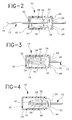
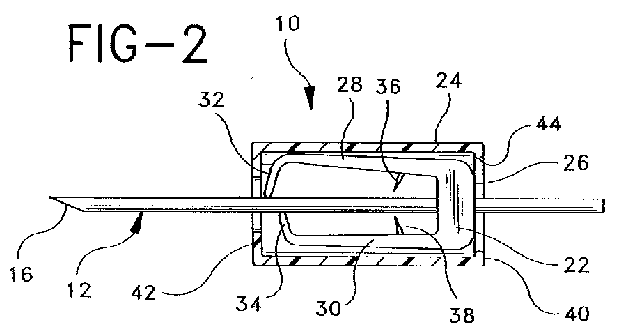
- Fig. 1 is a perspective view of a hypodermic syringe and a safety shield in accordance with the subject invention.
- Fig. 2 is a cross-sectional view taken along line 2-2 in Fig. 1.
- Fig. 3 is a cross-sectional view similar to Fig. 2, but showing the needle cannula and safety shield assembly in a fully shielded condition.
- Fig. 4 is a cross-sectional view similar to Figs. 2 and 3, but showing the outer shield partly disengaged from the inner shield.
- Fig. 5 is a perspective view similar to Fig. 1 but showing the outer shield fully separated from the inner shield.
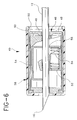
- Fig. 6 is a cross-sectional view similar to Fig. 2, but showing a second embodiment of an inner shield.
- Fig. 7 is a cross-sectional view showing the inner shield of Fig. 6 shielding the cannula tip of the outer shield partially disengaged from the inner shield.
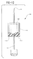
- Fig. 8 is a perspective view, partly in section, showing a third embodiment of inner and outer shields disposed in the retracted needle tip exposing position on a needle cannula.
- Fig. 9 is a cross-sectional view showing a fifth embodiment of the inner shield and outer shields.
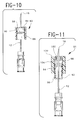
- Fig. 10 is a cross-sectional view similar to Fig. 2, but showing an alternate engagement between the inner and outer shields.
- Fig. 11 is a cross-sectional view similar to Fig. 10, but showing another alternate engagement between the inner and outer shield.
- Safety shield assembly 10 is identified generally by the numeral 10 in Figs. 1-5.
- Safety shield assembly 10 is slidably disposed on a needle cannula 12 having a proximal end 14, a sharp distal tip 16 and a lumen extending therebetween.
- Proximal end 14 of needle cannula 12 is securely mounted to a hub 18 which is threadedly engageable with a hypodermic syringe 20.
- Safety assembly 10 initially is releasably engaged or positioned near proximal end 14 of needle cannula 12. However, safety shield assembly 10 can be slid distally in response to force F s exerted thereon by a thumb and forefinger as shown in Fig. 1.
- Safety shield assembly 10 includes an inner shield 22 and an outer shield 24 releasably engaged over the inner shield 22.
- the inner shield may take any of several different forms.
- inner shield 22 is substantially similar to the shield depicted in the above-referenced U.S. Patent No. 4,929,241. More particularly, the proximal end of inner shield 22 defines a base 26 slidably mounted over needle cannula 12.
- Lever arms 28 and 30 project distally from base 26 and include inwardly directed ends 32 and 34 respectively. As shown in Fig. 2, ends 32 and 34 are in sliding engagement with the outer cylindrical surface of needle cannula 12. In this condition lever arms 28 and 30 respectively are preloaded away from needle cannula 12.
- Lever arms 28 and 30 further include locking teeth 36 and 38 respectively which project inwardly toward needle cannula 12 from locations intermediate the respective lengths of lever arms 28 and 30.
- Locking teeth 36 and 38 are dimensioned to be spaced from needle cannula 12 when ends 32 and 34 of lever arms 28 and 30 are in sliding engagement with needle cannula 12.
- Outer shield 24 is preferably a generally cylindrical structure having opposed proximal and distal ends 40 and 42 respectively. Outer shield 24 preferably defines an axial length greater than the corresponding axial length of inner shield 22. Thus, inner shield 22 is substantially inaccessible, and outer shield assembly 24 will define the region of all manual contact with shield assembly 10.
- Proximal end 40 of outer shield 24 includes a radially inwardly extending flange 44 which is dimensioned to releasably engage radial outer portions of base 26 at the proximal end of inner shield 22. Flange 44 will separate from inner shield 22 if relative forces between inner and outer shields 22 and 24 approach the breakaway force, F b .
- Distally directed forces of F s exerted on outer shield 24 will cause an initial sliding movement of the entire shield assembly 10 distally indicated as direction "A" in Fig. 1, without separating outer shield 24 from inner shield 22.
- Sufficient distal movement of shield assembly 10 will cause ends 32 and 34 of lever arms 28 and 30 to pass beyond distal end 16 of needle cannula 12.
- the preload referred to above will cause arms 28 and 30 to resiliently return toward an undeflected condition, such that ends 32 and 34, protectively enclose distal tip 16 of needle cannula 12 to prevent proximal movement of the needle shield, and such that teeth 36 and 38 grippingly engage the outer circumferential surface of needle cannula 12 to help prevent further distal movement of the needle shield.
- the inner shield can take many other optional configurations for protectively enclosing distal tip 16 of needle cannula 12.
- a shield assembly 45 having an inner shield 46 substantially as shown in WIPO Publication No. PCT/CA90/0031.
- inner shield 46 in Figs. 6 and 7 includes an inner shield housing 48 which contains a wedge actuator 50 in clipping engagement over needle cannula 12.
- a biased actuator 52 also is slidably mounted to needle cannula 12 in a position distally of wedge actuator 50.
- Clamp 54 is in sliding engagement with needle cannula 12 at a first location intermediate wedge actuator 50 and biased actuator 52, and at a second position distally of biased actuator 52. Clamp 54 also is engaged by wedge actuator 50.
- a coil spring 56 extends between biased actuator 52 and clamp 54.
- Spring 56 will cause clamp 54 to rotate counter clockwise as shown in Fig. 7. This rotation will cause the distal end of clamp 54 to protectively enclose distal tip 16 of syringe barrel 12, and will simultaneously cause proximal portions of clamp 54 inside aperture 55 in the clamp to grippingly engage needle cannula 12.
- Wedge actuator 50 will drive clamp 54 into tighter clamping engagement in response to distally directed axially forces exerted on inner shield 46. As noted above, some force F f will exist beyond which failure of inner shield 46 will occur.
- Outer shield 58 prevents such failure from occurring. More particularly, outer shield 58 substantially completely encloses inner shield 46 to prevent direct manual contact with any portion of inner shield 46.
- Outer shield 58 also includes a ridge 60 for releasably griping the proximal end of inner shield 46. Outer shield 58 will separate from inner shield 46 in response to a breakaway force F b which exceeds the force required to slidably move the entire shield assembly along needle cannula 123, but which is less than the failure force F f .
- the shield assembly shown in Figs. 6 and 7 will function substantially the same as the shield assembly of Figs. 24 despite the significantly different construction of the inner shield.
- Shield assembly 61 includes an inner shield 62 substantially as disclosed in U.S. Patent No. 5,053,017. More particularly, inner shield 62 is stamped and formed from a unitary strip of spring metal and includes a proximally disposed base 64 having an aperture 65 for slidably engaging needle cannula 12. Arms 66 and 68 extend from base 64 and include ends which are in sliding contact with the needle cannula. Arm 66 is preloaded and biased away from needle cannula 12.
- Shield assembly 61 further includes an outer shield 70 having inwardly facing cantilever members 71 capable of releasably engaging the inner shield 62. Outer shield 70 will separate from inner shield 62 in response to a breakaway force F b which is greater than the force F s required to slide inner shield 62 along needle cannula 12.
- breakaway force is the force required to deflect the cantilevers 71 as they pass over the largest portion of the inner shield.
- breakaway force F b to separate outer shield 70 from inner shield 62 is less than the force F f that will cause failure of inner shield 62 on needle cannula 12.
- a needle shield assembly 75 is shown in Fig. 9, and includes an inner shield 76 substantially similar to the shield shown in U.S. Patent No. 4,8456,811.
- Inner shield 76 includes an annular engagement groove 78 for engaging a bead 80 on the needle cannula 12.
- Shield assembly 10c further includes an outer shield 82 releasably engaged with inner shield 76.
- outer shield 82 will separate from inner shield 76 in response to a breakaway force F b which is greater than the force F s required to slide inner shield 76 along needle cannula 12, but less than the failure force F f required to separate inner shield 76 from annular bead 80 on needle cannula 12.12
- FIG. 10 shows a shield assembly 83 having an inner shield 84 with an annular groove 86 intermediate its length.
- Inner shield 84 may include locking means as shown in some of the above described embodiments.
- Shield assembly 83 further includes an outer shield 88 having an inwardly extending annular bead 90, or separate inwardly directed projections, releasably engaged in annular groove 86 of inner shield 84.
- outer shield 88 will separate from inner shield 84 in response to a breakaway force F b which is greater than the force F s required to slide the inner shield 84 along the needle cannula 12, but less than the failure force F f at which the locking structure of the inner shield 84 to the needle cannula fails.
- FIG. 11 shows a shield assembly 91 where an inner shield 92 includes an annular locking groove 94 on an inwardly facing surface 96 near distal end 98.
- An outer shield 100 has a proximally projecting sleeve 102 with a locking bead 104 for releasable engagement in groove 94 of inner shield 92.
- outer shield 100 will separate from inner shield 92 in response to a breakaway force F b which is greater than the force F s required to slide inner shield 92 axially along needle cannula 12, but less than the force F f at which the locking mechanism of inner shield 92 fails.
- the links may be formed by integrally molding the inner and outer shields at the same time.
- the frangible connection may be provided by connecting the inner and outer shields with adhesive-backed laminated sheet material, such as paper label stock or plastic sheet, designed to fracture at a preselected F b .
- Flexible links may also be molded on one of the shields and attached to the other shield using adhesive, mechanical joining, ultrasonic welding or the like.
Abstract
Description
- The subject invention relates to safety shields that are axially movable along a needle cannula from a proximal position where the tip of the needle cannula is exposed to a distal position where the tip of the needle cannula is protectively enclosed.
- The prior art hypodermic syringe includes an elongate barrel having an open proximal end, a distal end and a fluid receiving chamber therebetween. The distal end of the prior art syringe barrel defines a tip having a fluid passage extending therethrough and communicating with the chamber. A plunger may be slidably disposed in the open proximal end of the syringe barrel for urging fluid through the passage in the tip.
- A needle cannula can be mounted to the distal end of the prior art syringe barrel. The needle cannula has a proximal end, a sharp distal end and a lumen extending therebetween. The proximal end of the needle cannula is secured to a mounting hub that can be engaged on the distal end of the syringe barrel such that the passage through the distal end of the syringe barrel communicates with the lumen through the needle cannula.
- The prior art needle cannula is prepackaged in a needle shield to prevent accidental needle sticks prior to the first intended use of the needle cannula. The shield can be removed after the needle cannula has been mounted to the syringe barrel and immediately prior to use. A health care worker then uses the unshielded needle cannula and hypodermic syringe to either inject medication into a patient or to withdraw bodily fluid for subsequent diagnostic evaluation.
- Needle sticks that occur before the hypodermic syringe is used create less risk of infection because the needle is sterile. However, needle sticks occurring after the hypodermic syringe has been used pose a greater risk of infection or disease transmission. As a result, the prior art includes shields for protectively enclosing at least the tip of the used needle cannula.
- Some prior art shields define a separate cap that can be telescoped in a proximal direction over the used needle cannula. However, separate caps often are lost or misplaced in the hectic environment of a medical facility. Additionally, the movement of the used needle cannula and the separate cap toward one another creates the potential for an accidental needle stick.
- The prior art also includes needle shields that cannot be misplaced and that are intended to avoid the movement of one hand toward the other during a shielding operation. Needle shields of this type typically are releasably retained near the proximal end of the needle cannula. The distal end of the needle cannula is exposed and can be used in the standard manner. After use, however, the prior art needle shield can be slid distally along the needle cannula and into a shielding position.
- The prior art needle shield of this type typically includes means for lockingly engaging the needle cannula when the distal tip has been reached. The locking is intended to prevent further movement of the prior art shield in either a distal direction or a proximal direction. Distally directed movement of the locked prior art needle shield in some prior art devices is prevented by frictional or spring biased engagement of the shield with the smooth outer cylindrical surface of the needle cannula. Prior art shields of this general type are shown, for example, in: U.S. Patent No. 4,929,241; U.S. Patent No. 5,053,017 and WIPO Publication PCT/CA90/00031. Other prior art needle shields lockingly engage a discontinuity along the length of the needle cannula as shown in U.S. Patent No. 4,846,811.
- Prior art needle shields of the type described above can be designed to exert significant locking forces against the exterior surface of the needle cannula. However, all such prior art needle shields will have some limit to their locking force. The locking force will be limited by the design and will vary with the dimensional tolerances of the shield components. Thus, separation of the needle shield from the needle cannula can occur if the forces exceed the maximum locking force between the prior art needle shield and the needle cannula. Needle shields desirably should be as small as possible. However, smaller needle shields will exert lower gripping forces, and hence are more easily separated from the needle cannula.
- Separation of a prior art needle shield from a needle cannula may not require abusive use of the hypodermic syringe. Rather, separation can occur inadvertently if a health care worker accidentally exerts too much force in an effort to shield the needle cannula. Separation of the needle shield is accompanied by a sudden recognizable reduction in engagement forces between the shield and the needle cannula. The automatic reaction by the health care worker who inadvertently caused the separation is to attempt an immediate re-shielding by urging the shield back in a proximal direction. This is precisely the movement that shields of this type are intended to avoid. Under these circumstances, the re-shielding attempt will be an abrupt reactionary movement that can easily generate an accidental needle stick with a potentially contaminated needle.
- The subject invention is directed to a safety shield assembly. The safety shield assembly includes a rigid inner shield that slidably moves in response to a force Fs from a proximal position on a needle cannula to a distal position where the tip of the needle cannula is safely shielded. The inner shield may include means for sensing the distal end of the needle cannula and means for securely gripping the needle cannula when the distal tip of the needle cannula has been shielded. The locked inner shield may be prevented from a return or proximal movement along the needle cannula, and will move further distally only in response to a relatively great failure force Ff.
- The safety shield assembly also includes an outer shield substantially surrounding the inner shield. The outer shield is releasable engaged with the inner shield, and can be separated or broken from the inner shield in response to a breakaway force Fb The inner and outer shields are designed such that the breakaway force, Fb, is greater than the force Fs required to slide the inner safety shield along the needle cannula, but less than the force Ff required to separate the inner shield from the needle cannula.
- In most instances the health care worker will never know that the safety shield assembly includes two components. More particularly, the health care worker will merely grasp the outer shield in a standard manner, and will exert a force equal or slightly greater than Fs to slide the inner shield distally along the needle cannula. This force exerted by the health care worker typically will be less than the breakaway force Fb required to separate the outer shield from the inner shield. However, if the health care worker inadvertently or incorrectly exerts an excessive force on the safety shield assembly, the outer shield will separate from the inner shield when the breakaway force Fb is reached and well prior to the time when the failure force Ff is reached. Thus, such excessive force will merely separate the outer shield from the inner shield after locking has been achieved. The inner shield will remain safely in place in surrounding relationship to the distal tip of the needle cannula.
- Fig. 1 is a perspective view of a hypodermic syringe and a safety shield in accordance with the subject invention.
- Fig. 2 is a cross-sectional view taken along line 2-2 in Fig. 1.
- Fig. 3 is a cross-sectional view similar to Fig. 2, but showing the needle cannula and safety shield assembly in a fully shielded condition.
- Fig. 4 is a cross-sectional view similar to Figs. 2 and 3, but showing the outer shield partly disengaged from the inner shield.
- Fig. 5 is a perspective view similar to Fig. 1 but showing the outer shield fully separated from the inner shield.
- Fig. 6 is a cross-sectional view similar to Fig. 2, but showing a second embodiment of an inner shield.
- Fig. 7 is a cross-sectional view showing the inner shield of Fig. 6 shielding the cannula tip of the outer shield partially disengaged from the inner shield.
- Fig. 8 is a perspective view, partly in section, showing a third embodiment of inner and outer shields disposed in the retracted needle tip exposing position on a needle cannula.
- Fig. 9 is a cross-sectional view showing a fifth embodiment of the inner shield and outer shields.
- Fig. 10 is a cross-sectional view similar to Fig. 2, but showing an alternate engagement between the inner and outer shields.
- Fig. 11 is a cross-sectional view similar to Fig. 10, but showing another alternate engagement between the inner and outer shield.
- A safety shield assembly in accordance with the subject invention is identified generally by the numeral 10 in Figs. 1-5.
Safety shield assembly 10 is slidably disposed on aneedle cannula 12 having aproximal end 14, a sharpdistal tip 16 and a lumen extending therebetween.Proximal end 14 ofneedle cannula 12 is securely mounted to ahub 18 which is threadedly engageable with ahypodermic syringe 20. -
Safety assembly 10 initially is releasably engaged or positioned nearproximal end 14 ofneedle cannula 12. However,safety shield assembly 10 can be slid distally in response to force Fs exerted thereon by a thumb and forefinger as shown in Fig. 1. -
Safety shield assembly 10 includes aninner shield 22 and anouter shield 24 releasably engaged over theinner shield 22. The inner shield may take any of several different forms. As shown in Figs. 24,inner shield 22 is substantially similar to the shield depicted in the above-referenced U.S. Patent No. 4,929,241. More particularly, the proximal end ofinner shield 22 defines a base 26 slidably mounted overneedle cannula 12. Leverarms base 26 and include inwardly directed ends 32 and 34 respectively. As shown in Fig. 2, ends 32 and 34 are in sliding engagement with the outer cylindrical surface ofneedle cannula 12. In thiscondition lever arms needle cannula 12. Leverarms teeth needle cannula 12 from locations intermediate the respective lengths oflever arms teeth needle cannula 12 when ends 32 and 34 oflever arms needle cannula 12. -
Outer shield 24 is preferably a generally cylindrical structure having opposed proximal anddistal ends Outer shield 24 preferably defines an axial length greater than the corresponding axial length ofinner shield 22. Thus,inner shield 22 is substantially inaccessible, andouter shield assembly 24 will define the region of all manual contact withshield assembly 10. -
Proximal end 40 ofouter shield 24 includes a radially inwardly extendingflange 44 which is dimensioned to releasably engage radial outer portions ofbase 26 at the proximal end ofinner shield 22.Flange 44 will separate frominner shield 22 if relative forces between inner andouter shields - Distally directed forces of Fs exerted on
outer shield 24 will cause an initial sliding movement of theentire shield assembly 10 distally indicated as direction "A" in Fig. 1, without separatingouter shield 24 frominner shield 22. Sufficient distal movement ofshield assembly 10 will cause ends 32 and 34 oflever arms distal end 16 ofneedle cannula 12. The preload referred to above will causearms distal tip 16 ofneedle cannula 12 to prevent proximal movement of the needle shield, and such thatteeth needle cannula 12 to help prevent further distal movement of the needle shield. - Most health care workers will detect the locking of
shield assembly 10 toneedle cannula 12 and will stop their exertion of axial forces thereon. However, inexperienced health care workers or workers distracted by exigencies of a medical facility may continue to exert axial forces onshield assembly 10 after the Fig. 3 locked engagement has been achieved.Inner shield 22 will resist distally directed force up to a force Ff beyond which failure of the locked engagement toneedle cannula 12 will occur. However, the breakaway force Fb between inner andouter shields outer shield 24 after the locked Fig. 3 position has been achieved will merely causeflange 44 to disengage frominner shield 22 as shown in Fig. 4. Continued force will cause the complete separation ofouter shield 24 frominner shield 22 as shown in Fig. 5. However,inner shield 22 will remain protectively engaged in shielding relationship todistal point 16 ofneedle cannula 12 substantially as shown in Figs. 3 and 4. Thus, even if the health care worker appreciates his or her error and attempts tore-shield needle cannula 12, an accidental needle stick will be positively prevented by the continued gripping engagement ofinner shield 22 withneedle cannula 12. - The inner shield can take many other optional configurations for protectively enclosing
distal tip 16 ofneedle cannula 12. For example, in Fig. 6, ashield assembly 45 having aninner shield 46 substantially as shown in WIPO Publication No. PCT/CA90/0031. More particularly,inner shield 46 in Figs. 6 and 7 includes aninner shield housing 48 which contains awedge actuator 50 in clipping engagement overneedle cannula 12. Abiased actuator 52 also is slidably mounted toneedle cannula 12 in a position distally ofwedge actuator 50.Clamp 54 is in sliding engagement withneedle cannula 12 at a first locationintermediate wedge actuator 50 andbiased actuator 52, and at a second position distally ofbiased actuator 52.Clamp 54 also is engaged bywedge actuator 50. Acoil spring 56 extends betweenbiased actuator 52 andclamp 54.Spring 56 will causeclamp 54 to rotate counter clockwise as shown in Fig. 7. This rotation will cause the distal end ofclamp 54 to protectively enclosedistal tip 16 ofsyringe barrel 12, and will simultaneously cause proximal portions ofclamp 54 insideaperture 55 in the clamp to grippingly engageneedle cannula 12. Wedge actuator 50 will driveclamp 54 into tighter clamping engagement in response to distally directed axially forces exerted oninner shield 46. As noted above, some force Ff will exist beyond which failure ofinner shield 46 will occur.Outer shield 58 prevents such failure from occurring. More particularly,outer shield 58 substantially completely enclosesinner shield 46 to prevent direct manual contact with any portion ofinner shield 46.Outer shield 58 also includes aridge 60 for releasably griping the proximal end ofinner shield 46.Outer shield 58 will separate frominner shield 46 in response to a breakaway force Fb which exceeds the force required to slidably move the entire shield assembly along needle cannula 123, but which is less than the failure force Ff. Thus, the shield assembly shown in Figs. 6 and 7 will function substantially the same as the shield assembly of Figs. 24 despite the significantly different construction of the inner shield. - A third safety shield assembly that will perform similarly to the shield assemblies of Figs. 1-7, is shown in Fig. 8, and is identified generally by the numeral 61.
Shield assembly 61 includes aninner shield 62 substantially as disclosed in U.S. Patent No. 5,053,017. More particularly,inner shield 62 is stamped and formed from a unitary strip of spring metal and includes a proximally disposedbase 64 having anaperture 65 for slidably engagingneedle cannula 12.Arms base 64 and include ends which are in sliding contact with the needle cannula.Arm 66 is preloaded and biased away fromneedle cannula 12. Then, when the end ofarm 66 aligns withdistal tip 16 ofneedle cannula 12,arm 66 will resiliently return toward an undeflected condition, such that the end thereof protectively enclosesdistal tip 16 ofneedle cannula 12. Simultaneously,needle cannula 12 will be securely gripped bybase 64 in the area ofaperture 65.Shield assembly 61 further includes anouter shield 70 having inwardly facingcantilever members 71 capable of releasably engaging theinner shield 62.Outer shield 70 will separate frominner shield 62 in response to a breakaway force Fb which is greater than the force Fs required to slideinner shield 62 alongneedle cannula 12. In this embodiment the breakaway force is the force required to deflect thecantilevers 71 as they pass over the largest portion of the inner shield. However, as in the previous embodiment, breakaway force Fb to separateouter shield 70 frominner shield 62 is less than the force Ff that will cause failure ofinner shield 62 onneedle cannula 12. - The embodiments of the subject invention described and illustrated above all rely upon an
inner shield needle shield assembly 75 is shown in Fig. 9, and includes aninner shield 76 substantially similar to the shield shown in U.S. Patent No. 4,8456,811.Inner shield 76 includes anannular engagement groove 78 for engaging abead 80 on theneedle cannula 12. Shield assembly 10c further includes anouter shield 82 releasably engaged withinner shield 76. As in the previous embodiments,outer shield 82 will separate frominner shield 76 in response to a breakaway force Fb which is greater than the force Fs required to slideinner shield 76 alongneedle cannula 12, but less than the failure force Ff required to separateinner shield 76 fromannular bead 80 on needle cannula 12.12 - The embodiments described and illustrated above all included engagement means on the proximal end of the outer shield for releasably engaging the proximal end of the inner shield. Variations of this engagement are possible, and are shown schematically in Figs. 10 and 11. More particularly, Fig. 10 shows a
shield assembly 83 having aninner shield 84 with anannular groove 86 intermediate its length.Inner shield 84 may include locking means as shown in some of the above described embodiments.Shield assembly 83 further includes anouter shield 88 having an inwardly extendingannular bead 90, or separate inwardly directed projections, releasably engaged inannular groove 86 ofinner shield 84. As in the previous embodiments,outer shield 88 will separate frominner shield 84 in response to a breakaway force Fb which is greater than the force Fs required to slide theinner shield 84 along theneedle cannula 12, but less than the failure force Ff at which the locking structure of theinner shield 84 to the needle cannula fails. - Fig. 11 shows a
shield assembly 91 where aninner shield 92 includes anannular locking groove 94 on an inwardly facingsurface 96 neardistal end 98. Anouter shield 100 has aproximally projecting sleeve 102 with a lockingbead 104 for releasable engagement ingroove 94 ofinner shield 92. As in the previous embodiments,outer shield 100 will separate frominner shield 92 in response to a breakaway force Fb which is greater than the force Fs required to slideinner shield 92 axially alongneedle cannula 12, but less than the force Ff at which the locking mechanism ofinner shield 92 fails. - It is also within the purview of the instant invention to include connecting the inner shield and the outer shield by a frangible link or a plurality of frangible links. The links may be formed by integrally molding the inner and outer shields at the same time. The frangible connection may be provided by connecting the inner and outer shields with adhesive-backed laminated sheet material, such as paper label stock or plastic sheet, designed to fracture at a preselected Fb. Flexible links may also be molded on one of the shields and attached to the other shield using adhesive, mechanical joining, ultrasonic welding or the like.
Claims (11)
- A safety shield assembly comprising:
a needle cannula having a proximal end, a distal end and a lumen therethrough;
an inner shield slidably movable along said needle cannula from a proximal position where said distal end of said needle cannula is exposed, to a distal position at least partially on said needle cannula where said distal end of said needle cannula is shielded;
locking means for helping to prevent said inner shield from moving distally with respect to said needle cannula when said inner shield is in said distal position on said needle cannula;
an outer shield disposed in surrounding relationship to said inner shield; and
means for selectively disengaging said outer shield from said inner shield in response to a distally directed force of a selected magnitude exerted on said outer shield, said distally directed force being less than a force required to move said inner shield distally off the needle cannula, after said inner shield is in said distal position. - The safety shield assembly of Claim 1, wherein said inner and outer shields each include opposed proximal and distal ends, said outer shield including deflectable locking means adjacent said proximal end for releasably engaging said proximal end of said inner shield.
- The safety shield assembly of Claim 1, wherein said inner shield includes opposed proximal and distal ends and an engagement deformation therebetween, said outer shield including an engagement deformation releasably engageable with said engagement deformation of said inner shield.
- The safety shield assembly of Claim 3, wherein said engagement deformation of said inner shield comprises a recessed annular deformation therein, and wherein said engagement deformation of said outer shield is a projection releasably engageable with said recessed annular deformation of the inner shield.
- The safety shield assembly of Claim 1, wherein the inner shield includes opposed proximal and distal ends and opposed inner and outer surfaces, said inner shield including an engagement deformation on portions of said inner surface adjacent said distal end, said outer shield including opposed proximal and distal ends, said outer shield further comprising engagement means projecting proximally from said distal end for engagement with said engagement deformation of said inner shield.
- The safety shield assembly of Claim 1 wherein said means for selectively disengaging said outer shield from inner shield includes a frangible link connecting said outer shield to said inner shield.
- The safety shield assembly of Claim 6 wherein said frangible link comprises an adhesive backed sheet connected by said adhesive to said inner shield and said outer shield.
- The safety shield assembly of Claim 1 wherein said locking means is disposed in said inner shield for locking said inner shield to said cannula.
- The safety shield assembly of Claim 11 wherein said locking means includes a deformation on said cannula.
- The safety shield assembly of Claim 1 wherein said locking means includes a flexible link between structure adjacent to said proximal end of said needle cannula and said inner shield.
- The safety shield assembly of Claim 1, wherein locking means includes sensing means for sensing said distal end of said needle cannula and for locking said inner shield to said needle cannula upon said sensing of said end of said needle cannula by said sensing means.
Applications Claiming Priority (2)
| Application Number | Priority Date | Filing Date | Title |
|---|---|---|---|
| US08/102,874 US5344408A (en) | 1993-08-06 | 1993-08-06 | Break-away safety shield for needle cannula |
| US102874 | 1993-08-06 |
Publications (2)
| Publication Number | Publication Date |
|---|---|
| EP0638326A1 true EP0638326A1 (en) | 1995-02-15 |
| EP0638326B1 EP0638326B1 (en) | 1998-05-13 |
Family
ID=22292118
Family Applications (1)
| Application Number | Title | Priority Date | Filing Date |
|---|---|---|---|
| EP94305676A Expired - Lifetime EP0638326B1 (en) | 1993-08-06 | 1994-08-01 | Break-away safety shield for needle cannula |
Country Status (6)
| Country | Link |
|---|---|
| US (1) | US5344408A (en) |
| EP (1) | EP0638326B1 (en) |
| JP (1) | JP2709270B2 (en) |
| CA (1) | CA2129174C (en) |
| DE (1) | DE69410185T2 (en) |
| ES (1) | ES2116536T3 (en) |
Cited By (4)
| Publication number | Priority date | Publication date | Assignee | Title |
|---|---|---|---|---|
| EP1716882A1 (en) * | 2001-02-26 | 2006-11-02 | B. Braun Melsungen Ag | Protection device for an injection needle |
| CH700159A1 (en) * | 2008-12-30 | 2010-06-30 | Tripomed S R L | Protective device for August |
| EP1214115B2 (en) † | 1999-09-24 | 2012-02-22 | Becton Dickinson and Company | Compact needle point shield |
| WO2014007748A1 (en) * | 2012-07-04 | 2014-01-09 | Vigmed Ab | Needle shield for an injection needle assembly and injection needle assembly. |
Families Citing this family (124)
| Publication number | Priority date | Publication date | Assignee | Title |
|---|---|---|---|---|
| US6203527B1 (en) * | 1994-03-29 | 2001-03-20 | Filiberto P. Zadini | Bi-directional clamping guard for needle stick protection |
| US5423766A (en) * | 1994-08-26 | 1995-06-13 | Becton, Dickinson And Company | Safety shield having spring tether |
| US5549571A (en) * | 1995-04-18 | 1996-08-27 | Sak; Robert F. | Butterfly assembly with retractable needle cannula |
| US5882337A (en) * | 1995-06-07 | 1999-03-16 | Johnson & Johnson Medical, Inc. | Tip protection device |
| US5584810A (en) * | 1995-07-11 | 1996-12-17 | Becton Dickinson And Company | Needle point guard assembly |
| ATE481124T1 (en) | 1996-02-27 | 2010-10-15 | Braun Melsungen Ag | NEEDLE TIP PROTECTION FOR SUBCUTANEOUS INJECTIONS |
| US5651772A (en) * | 1996-02-28 | 1997-07-29 | Aeroquip Corporation | Needle guard assembly |
| US5817069A (en) * | 1996-02-28 | 1998-10-06 | Vadus, Inc. | Valve assembly |
| AU3900997A (en) * | 1996-08-07 | 1998-02-25 | Aeroquip Corporation | Needle protector |
| US5725503A (en) * | 1996-08-07 | 1998-03-10 | Aeroquip Corporation | Ratcheting needle protector assembly |
| US6080137A (en) * | 1997-01-08 | 2000-06-27 | Vadus, Inc. | Needle protector |
| US5954698A (en) * | 1997-01-08 | 1999-09-21 | Vadus, Inc. | Catheter apparatus having valved catheter hub and needle protector |
| US6616630B1 (en) * | 1997-08-20 | 2003-09-09 | B. Braun Melsungen A.G. | Spring clip safety IV catheter |
| US7125397B2 (en) * | 1997-08-20 | 2006-10-24 | B. Braun Melsungen Ag | Protective device for an injection needle |
| AU2012258325B2 (en) * | 1997-08-20 | 2013-01-31 | B. Braun Melsungen Ag | IV Catheter |
| US8211070B2 (en) * | 1997-08-20 | 2012-07-03 | B. Braun Melsungen Ag | Spring clip safety IV catheter |
| US6117108A (en) * | 1997-08-20 | 2000-09-12 | Braun Melsungen Ag | Spring clip safety IV catheter |
| US8382721B2 (en) | 1997-08-20 | 2013-02-26 | B. Braun Melsungen Ag | Spring clip safety IV catheter |
| AU2013248192B2 (en) * | 1997-08-20 | 2014-02-20 | B. Braun Melsungen Ag | IV Catheter |
| AU2014202597B2 (en) * | 1997-08-20 | 2015-09-03 | B. Braun Melsungen Ag | IV Catheter |
| US6280419B1 (en) | 1999-08-09 | 2001-08-28 | Arrow International, Inc. | Hypodermic needle guard |
| DE29921084U1 (en) * | 1999-12-01 | 2000-02-17 | Braun Melsungen Ag | Short catheter |
| AU772060C (en) * | 1999-12-21 | 2004-12-09 | Medex, Inc. | Needle safety device |
| US6406459B1 (en) | 1999-12-21 | 2002-06-18 | Butch Allmon | Needle safety device |
| US6210373B1 (en) * | 1999-12-30 | 2001-04-03 | Ethicon, Inc. | Needle safety cover |
| EP1153625A1 (en) * | 2000-05-09 | 2001-11-14 | Raphäel Pegaitaz | Security device for the point of a medical needle |
| JP4942256B2 (en) * | 2000-06-12 | 2012-05-30 | テルモ株式会社 | Puncture and indwelling needle assembly |
| US6585704B2 (en) | 2001-01-29 | 2003-07-01 | B. Braun Medical, Inc. | Method of retaining a tip protector on a needle with a curved tip |
| DE20102760U1 (en) * | 2001-02-16 | 2001-05-03 | Braun Melsungen Ag | Protective device for an injection needle with a curved tip |
| AU2007216913B2 (en) * | 2001-02-26 | 2010-12-23 | B.Braun Melsungen Ag | Protective device for a hypodermic needle |
| US7413562B2 (en) | 2001-03-15 | 2008-08-19 | Specialized Health Products, Inc. | Safety shield for medical needles |
| US6595955B2 (en) * | 2001-03-15 | 2003-07-22 | Specialized Health Products, Inc. | Safety shield for medical needles |
| US6796962B2 (en) * | 2001-03-15 | 2004-09-28 | Specialized Health Products, Inc. | Safety shield for medical needles |
| US6902546B2 (en) | 2001-03-15 | 2005-06-07 | Specialized Health Products, Inc. | Safety shield for medical needles |
| US7004927B2 (en) * | 2001-03-15 | 2006-02-28 | Specialized Health Products, Inc. | Safety shield for medical needles |
| US7179244B2 (en) * | 2001-03-15 | 2007-02-20 | Specialized Health Products, Inc. | Resettable safety shield for medical needles |
| US6984213B2 (en) * | 2001-03-15 | 2006-01-10 | Specialized Health Products, Inc. | Biopsy needle device |
| DE20106697U1 (en) * | 2001-04-18 | 2001-10-31 | Braun Melsungen Ag | Catheter introducer |
| MXPA04000481A (en) * | 2001-07-17 | 2004-07-23 | Hansen Bernd | Device for distributing substances. |
| CA2354462C (en) | 2001-07-30 | 2008-09-23 | William K. Reilly | Medical line stabilizer |
| ITBO20010497A1 (en) * | 2001-07-31 | 2003-01-31 | Delta Med S R L | PROTECTION DEVICE FOR NEEDLE-CANNULA |
| US6623458B2 (en) * | 2001-09-26 | 2003-09-23 | B. Braun Melsungen, Ag | Spring launched needle safety clip |
| US7354422B2 (en) * | 2001-09-26 | 2008-04-08 | B. Braun Melsungen Ag | Spring launched needle safety clip |
| US20040049155A1 (en) * | 2002-06-06 | 2004-03-11 | Schramm John B. | Needle tip protector |
| ES2808602T3 (en) * | 2002-06-20 | 2021-03-01 | Becton Dickinson Co | Catheter and introducer needle assembly with needle guard |
| DE20210394U1 (en) | 2002-07-04 | 2002-09-12 | Braun Melsungen Ag | catheter introducer |
| US7458954B2 (en) * | 2002-11-07 | 2008-12-02 | Specialized Health Products, Inc. | Safety shield for medical needles |
| US7115114B2 (en) * | 2003-05-02 | 2006-10-03 | Becton, Dickinson And Company | Medical device having releasable retainer |
| IL157981A (en) | 2003-09-17 | 2014-01-30 | Elcam Medical Agricultural Cooperative Ass Ltd | Auto-injector |
| US7988664B2 (en) | 2004-11-01 | 2011-08-02 | Tyco Healthcare Group Lp | Locking clip with trigger bushing |
| US7226434B2 (en) | 2003-10-31 | 2007-06-05 | Tyco Healthcare Group Lp | Safety shield |
| US6997902B2 (en) * | 2003-11-13 | 2006-02-14 | David L. Thorne | Safety shield for medical needles |
| CA2545208C (en) * | 2003-11-25 | 2011-02-22 | Specialized Health Products, Inc. | Resettable safety shield for medical needles |
| US7513888B2 (en) * | 2004-02-17 | 2009-04-07 | Smiths Medical Asd, Inc. | Needle guards |
| IL160891A0 (en) | 2004-03-16 | 2004-08-31 | Auto-mix needle | |
| US7651476B2 (en) * | 2004-09-28 | 2010-01-26 | B. Braun Medical Inc. | Protective clips |
| US7905857B2 (en) | 2005-07-11 | 2011-03-15 | Covidien Ag | Needle assembly including obturator with safety reset |
| US7850650B2 (en) | 2005-07-11 | 2010-12-14 | Covidien Ag | Needle safety shield with reset |
| US7828773B2 (en) | 2005-07-11 | 2010-11-09 | Covidien Ag | Safety reset key and needle assembly |
| JP4740996B2 (en) * | 2005-03-07 | 2011-08-03 | アースキン メディカル エルエルシー | Needle protection device |
| US7314462B2 (en) | 2005-04-12 | 2008-01-01 | Span-America Medical Systems, Inc. | Passive needle-stick protector |
| US20060276747A1 (en) | 2005-06-06 | 2006-12-07 | Sherwood Services Ag | Needle assembly with removable depth stop |
| US8043300B2 (en) * | 2005-07-05 | 2011-10-25 | Alcon, Inc. | Handpiece tip assembly |
| US7731692B2 (en) | 2005-07-11 | 2010-06-08 | Covidien Ag | Device for shielding a sharp tip of a cannula and method of using the same |
| US7632243B2 (en) * | 2005-08-08 | 2009-12-15 | Smiths Medical Asd, Inc. | Duckbill catheter release mechanism |
| US8162881B2 (en) * | 2005-08-08 | 2012-04-24 | Smiths Medical Asd, Inc. | Needle guard mechanism with angled strut wall |
| US8251950B2 (en) | 2005-08-08 | 2012-08-28 | Smiths Medical Asd, Inc. | Needle guard clip with heel |
| US8403886B2 (en) * | 2005-08-08 | 2013-03-26 | Smiths Medical Asd, Inc. | Needle guard clip with lip |
| BRPI0614085A2 (en) * | 2005-08-08 | 2012-12-25 | Smiths Medical Asd Inc | safety catheter device, needle guards and needle guard clip, and generally consistent removal forces obtaining method of a duckbill release mechanism |
| US20070038182A1 (en) * | 2005-08-08 | 2007-02-15 | Bialecki Dennis M | Needle guard mechanism with needle support |
| US7654735B2 (en) | 2005-11-03 | 2010-02-02 | Covidien Ag | Electronic thermometer |
| JP4921779B2 (en) | 2005-11-28 | 2012-04-25 | 日本コヴィディエン株式会社 | Indwelling needle |
| US7658725B2 (en) * | 2006-02-16 | 2010-02-09 | Smiths Medical Asd, Inc. | Enclosed needle device with duckbill release mechanism |
| CN101415456B (en) | 2006-03-29 | 2012-06-27 | 泰尔茂株式会社 | Protector |
| US20080097330A1 (en) * | 2006-07-18 | 2008-04-24 | Smiths Medical Asd, Inc. | Catheter insertion device with fluid leakage control |
| CN101112639B (en) * | 2006-07-27 | 2012-07-18 | 贝克顿·迪金森公司 | Vessel having a safeguard device and introducing needle component |
| US8382718B2 (en) | 2006-07-31 | 2013-02-26 | B. Braun Melsungen Ag | Needle assembly and components thereof |
| US8308691B2 (en) | 2006-11-03 | 2012-11-13 | B. Braun Melsungen Ag | Catheter assembly and components thereof |
| JP4994775B2 (en) | 2006-10-12 | 2012-08-08 | 日本コヴィディエン株式会社 | Needle point protector |
| JP5337713B2 (en) * | 2007-02-07 | 2013-11-06 | ベクトン・ディキンソン・アンド・カンパニー | Safety shield system and infusion device for single-use flexible compression syringes |
| US8888713B2 (en) | 2007-03-07 | 2014-11-18 | Becton, Dickinson And Company | Safety blood collection assembly with indicator |
| MX2009009508A (en) | 2007-03-07 | 2009-09-16 | Becton Dickinson Co | Safety blood collection assembly with indicator. |
| EP2279770B1 (en) * | 2007-07-17 | 2012-07-11 | Poly Medicure Ltd. | Needle |
| WO2009042874A1 (en) | 2007-09-27 | 2009-04-02 | Tyco Healthcare Group Lp | I.v. catheter assembly and needle safety device |
| US8357104B2 (en) | 2007-11-01 | 2013-01-22 | Coviden Lp | Active stylet safety shield |
| NZ585524A (en) * | 2007-11-21 | 2013-03-28 | Becton Dickinson Co | A safety needle guard with a cannula passing through a multi slot aperture |
| AU2008326334B2 (en) | 2007-11-21 | 2013-12-12 | Becton, Dickinson And Company | Needle safety device |
| EP2075029B1 (en) | 2007-12-20 | 2010-09-29 | Tyco Healthcare Group LP | Locking cap assembly with spring-loaded collar |
| UA100143C2 (en) * | 2008-03-17 | 2012-11-26 | Поли Медикьюэ Лимитед | Needle safety device and intravenous catheter |
| US7785296B2 (en) * | 2008-07-17 | 2010-08-31 | Smiths Medical Asd, Inc. | Needle tip spring protector |
| EP2216069B1 (en) * | 2009-02-06 | 2014-01-22 | VistaMed R & D Ltd. | Catheter introducer |
| DK2403568T3 (en) * | 2009-03-05 | 2015-03-23 | Sanofi Aventis Deutschland | Needle device |
| US8936575B2 (en) * | 2009-03-19 | 2015-01-20 | Becton, Dickinson And Company | Cannula-tip shielding mechanism |
| DE102009020061A1 (en) | 2009-05-06 | 2010-11-11 | B. Braun Melsungen Ag | Needle protection device for a medical hollow needle |
| SE534021C2 (en) * | 2009-08-13 | 2011-04-05 | Vigmed Ab | Protective device for a catheter needle tip |
| US8382751B2 (en) | 2009-09-10 | 2013-02-26 | Covidien Lp | System and method for power supply noise reduction |
| SE535169C2 (en) | 2010-04-13 | 2012-05-08 | Vigmed Ab | Polymer protective device for a catheter needle tip |
| CN102917750B (en) * | 2010-04-16 | 2015-11-25 | 保利医疗用品有限公司 | catheter device |
| WO2012023938A1 (en) | 2010-08-19 | 2012-02-23 | West Pharmaceutical Services, Inc. | Rigid needle shield |
| EP2618874B2 (en) | 2010-09-23 | 2023-02-22 | Greiner Bio-One GmbH | Needle tip shielding device |
| ES2725777T3 (en) | 2010-12-02 | 2019-09-27 | Erskine Medical Llc | Release mechanism for use with needle protection devices |
| AU2011336340B2 (en) | 2010-12-02 | 2015-06-18 | Erskine Medical Llc | Needle shield assembly with hub engagement member for needle device |
| BR112013025506A2 (en) | 2011-04-07 | 2016-12-27 | Erskine Medical Llc | needle device |
| ES2662356T3 (en) | 2011-04-27 | 2018-04-06 | Kpr U.S., Llc | Safety IV catheter assemblies |
| WO2013048768A1 (en) | 2011-09-26 | 2013-04-04 | Covidien Lp | Safety iv catheter and needle assembly |
| WO2013048975A1 (en) | 2011-09-26 | 2013-04-04 | Covidien Lp | Safety catheter |
| WO2013056223A1 (en) | 2011-10-14 | 2013-04-18 | Covidien Lp | Safety iv catheter assembly |
| EP2586479A1 (en) * | 2011-10-31 | 2013-05-01 | Sanofi-Aventis Deutschland GmbH | Safety needle assembly |
| DE102011119031A1 (en) | 2011-11-15 | 2013-05-16 | Adrian Jung | Safety cannula for withdrawing body fluids and medication of fluids in human and veterinary sectors, has movable part attached on needle protector or cannula or sleeve, where needle protector is manually moved in direction of needle tip |
| DE102011119032A1 (en) | 2011-11-15 | 2013-05-16 | Adrian Jung | Safety needle for withdrawing bodily fluids and administering fluids in human, has movable element which is attached at needle protector or cannula or envelope, so that needle protector is manually moved towards needle tip |
| DE102011119030A1 (en) | 2011-11-15 | 2013-05-16 | Adrian Jung | Safety Cannula for withdrawing bodily fluids and administering fluids in human, has movable element which is attached at needle protector or cannula or envelope, so that needle protector is manually moved towards needle tip |
| US8414539B1 (en) | 2011-12-27 | 2013-04-09 | B. Braun Melsungen Ag | Needle tip guard for percutaneous entry needles |
| JP2013202073A (en) * | 2012-03-27 | 2013-10-07 | Sumitomo Bakelite Co Ltd | Medical needle assembly |
| CN102813986B (en) * | 2012-07-29 | 2014-04-30 | 梁德富 | Self-destructive mechanism of axial filling adhesive type disposable blood sampling syringe needle |
| US10918837B2 (en) * | 2013-12-04 | 2021-02-16 | B. Braun Melsungen Ag | Safety needle assemblies and related methods |
| US9555221B2 (en) | 2014-04-10 | 2017-01-31 | Smiths Medical Asd, Inc. | Constant force hold tip protector for a safety catheter |
| WO2016178974A1 (en) | 2015-05-01 | 2016-11-10 | Centurion Medical Products Corporation | Catheter insertion system |
| US10980522B2 (en) | 2016-10-18 | 2021-04-20 | Piper Access, Llc | Intraosseous access devices, systems, and methods |
| WO2018165334A1 (en) | 2017-03-07 | 2018-09-13 | Piper Access, Llc. | Safety shields for elongated instruments and related systems and methods |
| CA3050963A1 (en) | 2017-03-10 | 2018-09-13 | Piper Access, Llc. | Securement devices, systems, and methods |
| US11559632B2 (en) | 2017-04-20 | 2023-01-24 | Embecta Corp. | Passive safety needle shield |
| US10500375B2 (en) | 2017-07-31 | 2019-12-10 | Becton, Dickinson And Company | Catheter assembly |
| US10828467B2 (en) | 2017-11-30 | 2020-11-10 | Becton, Dickinson And Company | Catheter assembly |
| EP3755247B1 (en) | 2018-02-20 | 2023-07-05 | Piper Access, LLC | Drilling devices and related methods |
Citations (9)
| Publication number | Priority date | Publication date | Assignee | Title |
|---|---|---|---|---|
| US4846811A (en) | 1987-01-29 | 1989-07-11 | International Medical Innovators, Inc. | Sliding sheath for medical needles |
| EP0352928A1 (en) * | 1988-07-11 | 1990-01-31 | Critikon, Inc. | I.V. catheter with self-locating needle guard |
| WO1990008564A1 (en) * | 1989-02-01 | 1990-08-09 | 167300 Canada Inc. | Disposable automatic hypodermic needle guard |
| US4964854A (en) * | 1989-01-23 | 1990-10-23 | Luther Medical Products, Inc. | Intravascular catheter assembly incorporating needle tip shielding cap |
| US4978344A (en) * | 1988-08-11 | 1990-12-18 | Dombrowski Mitchell P | Needle and catheter assembly |
| WO1991001151A1 (en) | 1989-07-17 | 1991-02-07 | Don Mclees | Needle tip guard |
| US5051109A (en) * | 1990-07-16 | 1991-09-24 | Simon Alexander Z | Protector for catheter needle |
| US5053017A (en) | 1990-02-28 | 1991-10-01 | Chamuel Steven R | Hypodermic needle safety clip |
| WO1992022344A1 (en) * | 1991-06-17 | 1992-12-23 | Sero-Guard Corporation | Needle guard for intravenous catheter placement |
Family Cites Families (11)
| Publication number | Priority date | Publication date | Assignee | Title |
|---|---|---|---|---|
| US4636201A (en) * | 1985-11-01 | 1987-01-13 | American Hospital Supply Corporation | Hypodermic syringe having a protective sheath cover |
| DE3827999A1 (en) * | 1988-07-01 | 1990-01-11 | Effner Gmbh | MEASURING DEVICE FOR OPERATING FORCES |
| US4892521A (en) * | 1988-08-03 | 1990-01-09 | Lincoln Mills, Inc. | Protective cover for hypodermic needle |
| US4929241A (en) * | 1988-08-05 | 1990-05-29 | Kulli John C | Medical needle puncture guard |
| US4911693A (en) * | 1988-10-17 | 1990-03-27 | Paris Frassetti R | Hypodermic syringe needle guard |
| US4955866A (en) * | 1988-10-19 | 1990-09-11 | University Of Florida | Hypodermic needle recapping device |
| US4986817A (en) * | 1988-11-22 | 1991-01-22 | International Development Systems, Inc. | Hypodermic syringe sheath holder and needle guide |
| US4981476A (en) * | 1988-12-02 | 1991-01-01 | Enslow, Inc. | Needle safety device |
| US4964866A (en) * | 1989-11-22 | 1990-10-23 | Becton, Dickinson And Company | Needle sheath assembly |
| US5085648A (en) * | 1990-09-13 | 1992-02-04 | Becton Dickinson And Company | Dual diameter needle with a smooth transition |
| US5171229A (en) * | 1991-04-15 | 1992-12-15 | Mcneil Michael B | Needle tip cover |
-
1993
- 1993-08-06 US US08/102,874 patent/US5344408A/en not_active Expired - Lifetime
-
1994
- 1994-07-29 CA CA002129174A patent/CA2129174C/en not_active Expired - Lifetime
- 1994-08-01 ES ES94305676T patent/ES2116536T3/en not_active Expired - Lifetime
- 1994-08-01 EP EP94305676A patent/EP0638326B1/en not_active Expired - Lifetime
- 1994-08-01 DE DE69410185T patent/DE69410185T2/en not_active Expired - Fee Related
- 1994-08-08 JP JP6185847A patent/JP2709270B2/en not_active Expired - Lifetime
Patent Citations (9)
| Publication number | Priority date | Publication date | Assignee | Title |
|---|---|---|---|---|
| US4846811A (en) | 1987-01-29 | 1989-07-11 | International Medical Innovators, Inc. | Sliding sheath for medical needles |
| EP0352928A1 (en) * | 1988-07-11 | 1990-01-31 | Critikon, Inc. | I.V. catheter with self-locating needle guard |
| US4978344A (en) * | 1988-08-11 | 1990-12-18 | Dombrowski Mitchell P | Needle and catheter assembly |
| US4964854A (en) * | 1989-01-23 | 1990-10-23 | Luther Medical Products, Inc. | Intravascular catheter assembly incorporating needle tip shielding cap |
| WO1990008564A1 (en) * | 1989-02-01 | 1990-08-09 | 167300 Canada Inc. | Disposable automatic hypodermic needle guard |
| WO1991001151A1 (en) | 1989-07-17 | 1991-02-07 | Don Mclees | Needle tip guard |
| US5053017A (en) | 1990-02-28 | 1991-10-01 | Chamuel Steven R | Hypodermic needle safety clip |
| US5051109A (en) * | 1990-07-16 | 1991-09-24 | Simon Alexander Z | Protector for catheter needle |
| WO1992022344A1 (en) * | 1991-06-17 | 1992-12-23 | Sero-Guard Corporation | Needle guard for intravenous catheter placement |
Cited By (6)
| Publication number | Priority date | Publication date | Assignee | Title |
|---|---|---|---|---|
| EP1214115B2 (en) † | 1999-09-24 | 2012-02-22 | Becton Dickinson and Company | Compact needle point shield |
| EP1716882A1 (en) * | 2001-02-26 | 2006-11-02 | B. Braun Melsungen Ag | Protection device for an injection needle |
| EP1707230B1 (en) | 2001-02-26 | 2016-02-17 | B. Braun Melsungen AG | Injection needle with a protection element for the needle tip |
| CH700159A1 (en) * | 2008-12-30 | 2010-06-30 | Tripomed S R L | Protective device for August |
| WO2014007748A1 (en) * | 2012-07-04 | 2014-01-09 | Vigmed Ab | Needle shield for an injection needle assembly and injection needle assembly. |
| CN104519933A (en) * | 2012-07-04 | 2015-04-15 | 威格米德公司 | Needle shield for an injection needle assembly and injection needle assembly |
Also Published As
| Publication number | Publication date |
|---|---|
| US5344408A (en) | 1994-09-06 |
| CA2129174A1 (en) | 1995-02-07 |
| DE69410185T2 (en) | 1998-11-05 |
| CA2129174C (en) | 1998-08-25 |
| JPH07148176A (en) | 1995-06-13 |
| JP2709270B2 (en) | 1998-02-04 |
| EP0638326B1 (en) | 1998-05-13 |
| ES2116536T3 (en) | 1998-07-16 |
| DE69410185D1 (en) | 1998-06-18 |
Similar Documents
| Publication | Publication Date | Title |
|---|---|---|
| US5344408A (en) | Break-away safety shield for needle cannula | |
| EP1221301B1 (en) | Blood collection set | |
| US5342309A (en) | Syringe having safety shield | |
| US6969376B2 (en) | Safety indwelling needle | |
| US9770200B2 (en) | Needle assembly with safety system for a syringe or fluid sampling device and method of making and using the same | |
| EP0753316A1 (en) | Lockable needle point guard | |
| US4874384A (en) | Needle safety guard | |
| US5336187A (en) | Automatic cover disposable syringe | |
| US6436070B1 (en) | Catheter insertion device with retractable needle | |
| JP3422025B2 (en) | Capture and retraction device for needle cannula | |
| US9480799B2 (en) | Retractable needle assembly utilizing a standard interface and syringe utilizing the same | |
| EP1221300B1 (en) | Needle assembly | |
| EP2566543B1 (en) | Needle safety device for medical devices | |
| EP0719564A1 (en) | Safety device for use in inserting a cannula | |
| EP2883561A1 (en) | Needle capture mechanisms | |
| EP0807443A2 (en) | Syringe and needle shield assembly | |
| JPH10113389A (en) | Medical injection device having safety shield body which can be locked | |
| US6659983B2 (en) | Needle assembly | |
| JPH0649074B2 (en) | Hypodermic syringe | |
| EP2281599A2 (en) | Safety system for a blood collection device | |
| WO1998057689A1 (en) | Shield for catheter introducer needles | |
| US20230129736A1 (en) | Autoinjector, method of activating an autoinjector and method of assembling an autoinjector | |
| EP3881882A1 (en) | Automatically retracting safety needle assembly | |
| CA2364963A1 (en) | Blood collection set | |
| WO1999062579A1 (en) | Hypodermic needle |
Legal Events
| Date | Code | Title | Description |
|---|---|---|---|
| PUAI | Public reference made under article 153(3) epc to a published international application that has entered the european phase |
Free format text: ORIGINAL CODE: 0009012 |
|
| AK | Designated contracting states |
Kind code of ref document: A1 Designated state(s): DE ES FR GB IT |
|
| 17P | Request for examination filed |
Effective date: 19950810 |
|
| 17Q | First examination report despatched |
Effective date: 19960430 |
|
| GRAG | Despatch of communication of intention to grant |
Free format text: ORIGINAL CODE: EPIDOS AGRA |
|
| GRAG | Despatch of communication of intention to grant |
Free format text: ORIGINAL CODE: EPIDOS AGRA |
|
| GRAH | Despatch of communication of intention to grant a patent |
Free format text: ORIGINAL CODE: EPIDOS IGRA |
|
| GRAH | Despatch of communication of intention to grant a patent |
Free format text: ORIGINAL CODE: EPIDOS IGRA |
|
| GRAA | (expected) grant |
Free format text: ORIGINAL CODE: 0009210 |
|
| AK | Designated contracting states |
Kind code of ref document: B1 Designated state(s): DE ES FR GB IT |
|
| REF | Corresponds to: |
Ref document number: 69410185 Country of ref document: DE Date of ref document: 19980618 |
|
| ITF | It: translation for a ep patent filed |
Owner name: MARIETTI E GISLON S.R.L. |
|
| ET | Fr: translation filed | ||
| REG | Reference to a national code |
Ref country code: ES Ref legal event code: FG2A Ref document number: 2116536 Country of ref document: ES Kind code of ref document: T3 |
|
| PGFP | Annual fee paid to national office [announced via postgrant information from national office to epo] |
Ref country code: ES Payment date: 19980814 Year of fee payment: 5 |
|
| PLBE | No opposition filed within time limit |
Free format text: ORIGINAL CODE: 0009261 |
|
| STAA | Information on the status of an ep patent application or granted ep patent |
Free format text: STATUS: NO OPPOSITION FILED WITHIN TIME LIMIT |
|
| 26N | No opposition filed | ||
| PG25 | Lapsed in a contracting state [announced via postgrant information from national office to epo] |
Ref country code: ES Free format text: LAPSE BECAUSE OF NON-PAYMENT OF DUE FEES Effective date: 19990802 |
|
| REG | Reference to a national code |
Ref country code: GB Ref legal event code: IF02 |
|
| REG | Reference to a national code |
Ref country code: ES Ref legal event code: FD2A Effective date: 20000911 |
|
| PGFP | Annual fee paid to national office [announced via postgrant information from national office to epo] |
Ref country code: DE Payment date: 20080930 Year of fee payment: 15 |
|
| PG25 | Lapsed in a contracting state [announced via postgrant information from national office to epo] |
Ref country code: DE Free format text: LAPSE BECAUSE OF NON-PAYMENT OF DUE FEES Effective date: 20100302 |
|
| PGFP | Annual fee paid to national office [announced via postgrant information from national office to epo] |
Ref country code: GB Payment date: 20130827 Year of fee payment: 20 Ref country code: FR Payment date: 20130819 Year of fee payment: 20 |
|
| PGFP | Annual fee paid to national office [announced via postgrant information from national office to epo] |
Ref country code: IT Payment date: 20130823 Year of fee payment: 20 |
|
| REG | Reference to a national code |
Ref country code: GB Ref legal event code: PE20 Expiry date: 20140731 |
|
| PG25 | Lapsed in a contracting state [announced via postgrant information from national office to epo] |
Ref country code: GB Free format text: LAPSE BECAUSE OF EXPIRATION OF PROTECTION Effective date: 20140731 |