EP0640331A2 - Closure device for hygienic articles, particularly diaper closure - Google Patents
Closure device for hygienic articles, particularly diaper closure Download PDFInfo
- Publication number
- EP0640331A2 EP0640331A2 EP94112557A EP94112557A EP0640331A2 EP 0640331 A2 EP0640331 A2 EP 0640331A2 EP 94112557 A EP94112557 A EP 94112557A EP 94112557 A EP94112557 A EP 94112557A EP 0640331 A2 EP0640331 A2 EP 0640331A2
- Authority
- EP
- European Patent Office
- Prior art keywords
- closure device
- adhesive
- self
- band
- diaper
- Prior art date
- Legal status (The legal status is an assumption and is not a legal conclusion. Google has not performed a legal analysis and makes no representation as to the accuracy of the status listed.)
- Granted
Links
Images

Classifications
-
- A—HUMAN NECESSITIES
- A61—MEDICAL OR VETERINARY SCIENCE; HYGIENE
- A61F—FILTERS IMPLANTABLE INTO BLOOD VESSELS; PROSTHESES; DEVICES PROVIDING PATENCY TO, OR PREVENTING COLLAPSING OF, TUBULAR STRUCTURES OF THE BODY, e.g. STENTS; ORTHOPAEDIC, NURSING OR CONTRACEPTIVE DEVICES; FOMENTATION; TREATMENT OR PROTECTION OF EYES OR EARS; BANDAGES, DRESSINGS OR ABSORBENT PADS; FIRST-AID KITS
- A61F13/00—Bandages or dressings; Absorbent pads
- A61F13/15—Absorbent pads, e.g. sanitary towels, swabs or tampons for external or internal application to the body; Supporting or fastening means therefor; Tampon applicators
- A61F13/56—Supporting or fastening means
- A61F13/58—Adhesive tab fastener elements
Definitions
- the invention relates to a closure device for hygiene articles, such as incontinence diapers, children's panties, incontinence pads or the like, for connecting two parts of the hygiene article, with the features specified in the preamble of claim 1.
- the invention relates to a diaper closure for connecting a front and rear part of a diaper in the area of the outside of the hip.
- the hygiene articles mentioned at the outset and in particular with incontinence pads or diapers for adults there is basically the problem that the article should be adaptable to different body dimensions of the wearer in order to achieve pleasant wearing properties and a fit that is as precise as possible.
- the hygiene articles should be at least to a certain extent resilient when worn in order to be able to adapt to movements of the wearer.
- buttons on the tape are used, which are to be buttoned into corresponding button holes on the pads.
- connection system is comparatively complex to manufacture, which has such a disposable character Deposits are difficult to reconcile.
- buttoning of the elastic band is relatively cumbersome.
- the invention has for its object to improve a closure device for hygiene articles of the generic type so that the connecting element is structurally simplified and more convenient to use while maintaining the elastic properties of the closure device.
- the closure device should act on its own and not make any changes, e.g. Buttonholes, need on the hygiene article.
- the connecting element on the elastic band has a non-elastic covering which stiffens the band at least in a partial area and to which a self-adhesive element for reversibly releasable connection of the band to the article is attached.
- stiffening the tape in a partial area the basis is created for a self-adhesive element to be used in conjunction with an otherwise elastic tape.
- the closure device on the one hand has the required elastic properties, on the other hand, complex connecting elements, such as the buttons and buttonholes, can be completely dispensed with in the closure device according to the prior art.
- the closure device according to the invention can be permanently fixed with one end of the elastic band, for example on the rear part of a diaper or incontinence pad, and reversible with the other band end detachable, for example connected to the front part of the diaper or insert.
- the closure device forms a unit with the diaper and is thrown away with it.
- a closure device according to the invention can also be used as a reusable part together with disposable diapers or inserts.
- a support stiffening the elastic band is arranged in the two end regions of the band.
- a self-adhesive element for the reversibly releasable connection of the tape to the article can be attached to the two tape ends.
- the closure device according to the invention thus forms a reusable closure system, which is often used with e.g. Disposable adult diapers can be used. This requires a further reduction in costs in the manufacture and use of the closure device according to the invention or the corresponding hygiene articles, since after use the article itself is disposed of, but the closure device can still be used.
- Claims 3 to 5 characterize advantageous embodiments for the stiffening pads on the elastic band.
- Plastic film strips are used, which are made of polyester. Impregnated or siliconized paper strips are also conceivable.
- the stiffening pad can fulfill a double function.
- it serves for the durable fastening of a self-adhesive element designed as a self-adhesive strip
- the corresponding double-sided support can act in the manner of a so-called release tape, as is used in conventional diaper adhesive closures.
- the entire adhesive surface of the self-adhesive strip is glued onto the support for the intermediate storage of the closure device and is thus protected from dirt and the like.
- Claims 7 to 10 characterize advantageous designs of the self-adhesive element, which are used to connect the inelastic support in each case the elastic band with the diaper. It should be added that the configuration according to claim 8 has particular advantages with regard to comfort and hygiene articles provided with a closure device according to the invention. Since the self-adhesive element consists of a self-adhesive strip which is naturally flexible, the part of the closure device to be stuck onto the hygiene article can adapt flexibly to the body shape of the wearer and thus does not call any pressure points or the like. forth. This flexibility also results in optimized adhesive behavior.
- the elastic band of the closure device can be made from e.g. textile rubber band, an elastic fleece, an elastic mesh or an elastic film, which only has to be elastic in the longitudinal direction of the belt.
- stiffening pads with different adhesive strengths for a self-adhesive strip to be attached are attached to the respective band end both on the inside and on the outside. For example, achieve a relatively low adhesive force on one side for a self-adhesive strip to be attached by means of a siliconized polyester film or a siliconized paper. A pad with such a low adhesive force is used where the pad acts as a release tape, i.e. where the self-adhesive strip with its adhesive surface is only stuck on for temporary storage until the next reuse.
- the support extending around the end of the band according to claim 6 is also provided on one side with a corresponding coating - for example siliconization.
- the incontinence diaper 1 shown in FIG. 1 has a conventional diaper structure, not shown in more detail, with a cellulose flake absorbent body, a body-side nonwoven layer and a liquid-impermeable cover layer 2 made of thin polyethylene film facing away from the body.
- the rear part 3 and the front part 4 of the incontinence diaper 1 overlap one another in the applied state of the diaper and thereby form leg openings 5.
- Front 4 and rear part 3 are connected to one another by closure devices 6 in the area of the outside of the hip.
- This closure device 6 consists essentially of an elongated, elastic band 7, which is a textile band made of polyester threads with woven Rubber threads.
- the elastic tape 7 has in its two end regions 8, 9 on both sides a stiffening pad 10, 11, which makes the elastic tape 7 inelastic, each serving as a fastening base for self-adhesive strips 12, 13.
- the latter are connected with their one longitudinal half 14 to the support 10 or 11 and glued to the second longitudinal half 15 in the applied state with the cover layer 2 of the diaper 1.
- the closure device 6 Because of the above-described configuration of the closure device 6, a reliable fixation of the two diaper parts 3, 4 to one another is achieved on the one hand.
- the elasticity of the band 7 allows the diaper 1 to adapt optimally to the wearer of the body between the two end regions 8, 9 and to ensure that the diaper fits perfectly even when the wearer moves.
- the two supports 10, 11 in the two end regions 8, 9 of the band 7 each consist of a rectangular plastic film strip 16 made of a non-stretchable polyester film with a thickness of 125 ⁇ m.
- the strips 16 are each glued to the strip 7 in the end regions 8, 9 of the strip 7 by means of an adhesive layer 17 made of a heat-activatable polyester hot-melt adhesive.
- the strips 16 are applied such that they extend from one longitudinal side 18 of the elastic band 7 around the band end 19 to the second longitudinal side 20. As indicated by a thickened line in FIG.
- the plastic film strip 16 has a coating 29 in the form of a siliconization on the side facing the diaper when the diaper is in position - that is to say on the side facing the longitudinal side 18 of the elastic band 7.
- this coating 29 the self-adhesive strips 12, 13 adhere less in this area than on the uncoated part of the plastic film strips 16.
- the self-adhesive strips 12, 13 can be removed more easily from this side of the supports 10, 11. This further simplifies the handling of the diaper closure system according to the invention.
- the procedure is such that a web of the polyester film is provided with the adhesive layer 17 by means of a rotary melt screen printing process.
- a sieve with a mesh size of 11 mesh is used, with which the adhesive is applied with an application weight of 50 g / m2 to form small knobs.
- the web thus coated is cut into strips 16 which, as shown in FIG. 3, are wrapped around the end regions 8, 9 of the band 7 in the unstretched state.
- the strips 16 are then ironed on both sides by pressing and the action of temperature, so that a firm bond of the strips 16 with the band 7 is produced in the end regions 8, 9. This firm bond means that the elastic band in the end areas 8.9 is no longer stretchable.
- the pads 10, 11 can thus serve as a stable base for the attachment of an adhesive element for connecting the tape 7 to the diaper 1.
- the self-adhesive strips 12, 13 generally addressed with reference to FIG. 1 consist of a strip-shaped impregnated paper carrier 21 which is provided on one side with a coating 22 made of a self-adhesive hot-melt adhesive composition based on styrene-isoprene-styrene block copolymers.
- the coating 22 is applied using a rotary melt screen printing method using a 25 mesh screen and with an application weight of 35 g / m 2.
- the self-adhesive strips 12, 13 can be glued to their full length on the supports 10, 11 in a stored state (see FIG. 3, left part), as a result of which the latter act as release tape.
- the self-adhesive strips 12, 13 are pulled off in half, which is facilitated by the grip end 23 on the adhesive strips 12, 13 that remains free of the coating 22.
- the longitudinal half 15 pulled off from the support 10, 11 is then pressed onto the cover layer 2 of the diaper 1 and thus glued (see FIGS. 2 and 3, right part).
- This bond is due to the nature and nub-shaped design of the coating 22 reversibly detachable, so that the self-adhesive strip 12, 13 is removed from a used diaper 1 and the entire closure device 6 can be reused with a new diaper.
- the self-adhesive strips 12, 13 can be temporarily stored on the supports 10, 11, as shown in the left part in FIG. 3.
- the self-adhesive strips 12, 13 in the region of their longitudinal halves 14 can be completely removed from the supports 10, 11 and new adhesive strips can be applied.
- German patent application P 42 02 704.7 for the production process of the coating 22 or the adhesive layer 17, in which the rotary screen printing process used is discussed in detail.
- a closure device 6 ' there is again an elastic band 7', which is provided in its two end regions 9 'on one side with a support 11' made of a thermoplastic coating 24 on a Long side 18 'of the band.
- the coating 24 is produced, for example, by casting on a molten thermoplastic, which connects intimately to the textile structure of the elastic band 7 'and is firmly anchored to the elastic band 7' after cooling.
- the coating 24 is in turn provided with an adhesive layer 25 formed from small knobs, which is applied with the aid of the rotary melt screen printing method already mentioned. In this way, the closure device 6 'can in turn be reversibly releasably connected to a diaper 1.
- FIG. 4 left part, an embodiment of a closure device 6 ′′ is shown, in which the basic design of the support 10 ′ that makes the rubber band 7 ′′ inelastic corresponds to the embodiment according to FIG. 3.
- a die cut is provided on the basis of an impregnated paper strip 26, which on the outside is covered with the previously mentioned knob-shaped adhesive layer 25 'made of self-adhesive Adhesive is provided.
- This adhesive layer 25 ' is in turn to be applied using the rotary melt screen printing method already mentioned.
- On the inside of the paper strip 26 there is a permanently self-adhesive layer 27 with which the paper strip 26 is permanently connected to the elastic band 7 ′′. This fixed connection in turn makes the end region 8 'inelastic.
- the inside of the paper strip 26 can also be coated with a heat-activatable adhesive layer, the permanent connection being produced by melting the adhesive.
- a cover strip 28 made of siliconized paper is applied to the adhesive layer 25, 25 'and is removed before the closure device 6' or 6 '' is used to expose the adhesive layer 25, 25 ''.
- the exemplary embodiment shown in FIG. 5 essentially corresponds to the exemplary embodiment according to FIG. 3. Corresponding parts are therefore provided with the same reference numerals. As a difference, however, the plastic film strip 16 'is not drawn around the band end 19, but is only attached in the region of the outside long side 20. It is an uncoated polyester film strip on which the self-adhesive strip 13 adheres very well. On the inside long side 18 a paper strip 26 'is applied over the adhesive layer 17, which in turn has a coating 29 in the form of a siliconization on its outside. The self-adhesive strip 13 can thus be easily removed from the “intermediate storage position” shown in FIG. 5 from the paper strip 26 ′ and can be moved into the active position shown in FIG. 3, right part.
Abstract
Description
Die Erfindung betrifft eine Verschlußvorrichtung für Hygieneartikel, wie Inkontinenz-, Kinderhöschenwindeln, Inkontinenzeinlagen oder dergleichen, zur Verbindung zweier Teile des Hygieneartikels, mit den im Oberbegriff des Patentanspruches 1 angegebenen Merkmalen. Insbesondere bezieht sich die Erfindung auf einen Winderverschluß zur Verbindung eines Vorder- und Hinterteils einer Windel im Bereich der Hüftaußenseiten.The invention relates to a closure device for hygiene articles, such as incontinence diapers, children's panties, incontinence pads or the like, for connecting two parts of the hygiene article, with the features specified in the preamble of
Beim Tragen der eingangs erwähnten Hygieneartikel und insbesondere bei Inkontinenzeinlagen oder Windeln für Erwachsene besteht grundsätzlich das Problem, daß eine Anpassung des Artikels an unterschiedliche Körpermaße der Träger möglich sein soll, um angenehme Trageeigenschaften und eine möglichst genaue Paßform zu erzielen. Darüber hinaus sollen die Hygieneartikel beim Tragen zumindest in einem gewissen Maße elastisch nachgiebig sein, um sich an Bewegungen des Trägers anpassen zu können.When wearing the hygiene articles mentioned at the outset and in particular with incontinence pads or diapers for adults, there is basically the problem that the article should be adaptable to different body dimensions of the wearer in order to achieve pleasant wearing properties and a fit that is as precise as possible. In addition, the hygiene articles should be at least to a certain extent resilient when worn in order to be able to adapt to movements of the wearer.
Zur Lösung der vorstehenden Probleme wurde bei Inkontinenzeinlagen für Erwachsene bereits vorgeschlagen, als Verschlußvorrichtung zwischen dem Vorder- und Hinterteil der Einlage ein elastisches Band zu verwenden. Als Verbindungselement zur reversibel lösbaren Verbindung des Bandes mit der Inkontinenzeinlage werden dabei Knöpfe an dem Band verwendet, die in entsprechende Knopflöcher an den Einlagen einzuknöpfen sind.To solve the above problems in incontinence pads for adults, it has already been proposed to use an elastic band as a closure device between the front and rear parts of the pad. As a connecting element for the reversibly releasable connection of the tape to the incontinence pad, buttons on the tape are used, which are to be buttoned into corresponding button holes on the pads.
Ein derartiges Verbindungssystem nach dem Stand der Technik ist vergleichsweise aufwendig herzustellen, was mit dem Wegwerf-Charakter solcher Einlagen nur schwer vereinbar ist. Darüber hinaus ist das Anknöpfen des elastischen Bandes relativ mühselig.Such a connection system according to the prior art is comparatively complex to manufacture, which has such a disposable character Deposits are difficult to reconcile. In addition, the buttoning of the elastic band is relatively cumbersome.
Weiterhin ist es insbesondere auf dem Gebiet von Kinder-Höschenwindeln bekannt, den Windelverschluß durch nicht-dehnbare Klebebänder zu realisieren. Die notwendige Elastifizierung der Höschenwindel zur Erzielung einer befriedigenden Paßform wird dabei durch in die Windel eingearbeitete Elastikteile wie dehnbare Hüftbündchen bewerkstelligt. Auch dies ist konstruktiv und herstellungstechnisch relativ aufwendig.Furthermore, it is known in particular in the field of children's pant diapers to implement the diaper closure by means of non-stretchable adhesive tapes. The necessary elasticization of the pant diaper to achieve a satisfactory fit is accomplished by elastic parts incorporated into the diaper, such as elastic waistbands. This is also relatively complex in terms of design and manufacturing technology.
Ausgehend vom den geschilderten Problemen beim Stande der Technik liegt der Erfindung die Aufgabe zugrunde, eine Verschlußvorrichtung für Hygieneartikel der gattungsgemäßen Art so zu verbessern, daß unter Beibehaltung der elastischen Eigenschaften der Verschlußvorrichtung deren Verbindungselement konstruktiv vereinfacht und bequemer handhabbar ist. Insbesondere soll die Verschlußvorrichtung aus sich heraus wirken und keine Veränderungen, wie z.B. Knopflöcher, am Hygieneartikel benötigen.Based on the problems described in the prior art, the invention has for its object to improve a closure device for hygiene articles of the generic type so that the connecting element is structurally simplified and more convenient to use while maintaining the elastic properties of the closure device. In particular, the closure device should act on its own and not make any changes, e.g. Buttonholes, need on the hygiene article.
Diese Aufgabe wird durch die im Kennzeichnungsteil des Anspruches 1 angegebenen Merkmale gelöst. Demnach weist das Verbindungselement am elastischen Band eine das Band zumindest in einem Teilbereich versteifende, unelastisch machende Auflage auf, an der ein Selbstklebeelement zur reversibel lösbaren Verbindung des Bandes mit dem Artikel angebracht ist. Durch die Versteifung des Bandes in einem Teilbereich wird dabei die Grundlage dafür geschaffen, daß ein Selbstklebelement in Verbindung mit einem ansonsten elastischen Band verwendet werden kann. Somit weist die Verschlußvorrichtung einerseits die geforderten elastischen Eigenschaften auf, andererseits können aufwendige Verbindungselemente, wie die Knöpfe und Knopflöcher bei der Verschlußvorrichtung gemäß dem Stand der Technik völlig entfallen.This object is achieved by the features specified in the characterizing part of
Grundsätzlich kann die erfindungsgemäße Verschlußvorrichtung mit einem Ende des elastischen Bandes dauerhaft, z.B. am Hinterteil einer Windel oder Inkontinenzeinlage, befestigt und mit dem anderen Bandende reversibel lösbar, z.B. mit dem Vorderteil der Windel oder Einlage verbunden werden. In diesem Falle bildet die Verschlußvorrichtung eine Einheit mit der Windel und wird mit ihr weggeworfen.In principle, the closure device according to the invention can be permanently fixed with one end of the elastic band, for example on the rear part of a diaper or incontinence pad, and reversible with the other band end detachable, for example connected to the front part of the diaper or insert. In this case, the closure device forms a unit with the diaper and is thrown away with it.
Andererseits kann eine erfindungsgemäße Verschlußvorrichtung auch als wiederverwendbares Teil zusammen mit Wegwerf-Windeln oder -Einlagen verwendet werden. Dazu ist gemäß Anspruch 2 vorgesehen, daß jeweils eine das elastische Band versteifende Auflage in den beiden Endbereichen des Bandes angeordnet ist. Entsprechend kann jeweils ein Selbstklebeelement zur reversibel lösbaren Verbindung des Bandes mit dem Artikel an den beiden Bandenden befestigt werden. Die erfindungsgemäße Verschlußvorrichtung bildet also ein wiederverwendbares Verschlußsystem, das vielfach mit z.B. Wegwerf-Erwachsenenwindeln verwendet werden kann. Dies bedingt eine weitere Kostensenkung bei der Herstellung und Anwendung der erfindungsgemäßen Verschlußvorrichtung bzw. der entsprechenden Hygieneartikel, da nach Gebrauch der Artikel selbst entsorgt wird, die Verschlußvorrichtung aber weiter einsetzbar ist.On the other hand, a closure device according to the invention can also be used as a reusable part together with disposable diapers or inserts. For this purpose, it is provided according to
Die Ansprüche 3 bis 5 kennzeichnen vorteilhafte Ausführungsformen für die versteifenden Auflagen an dem elastischen Band. Dabei können z.B. Kunststoff-Folienstreifen verwendet werden, die aus Polyester bestehen. Auch imprägnierte oder silikonisierte Papierstreifen sind denkbar.
Durch die Ausgestaltung der Verschlußvorrichtung nach Anspruch 6 kann die versteifende Auflage eine Doppelfunktion erfüllen. Einerseits dient sie zur haltbaren Befestigung eines als Selbstklebestreifen ausgebildeten Selbstklebeelementes, andererseits kann die entsprechend beidseitige Auflage nach Art eines sogenannten Release-Tapes wirken, wie es bei herkömmlichen Windel-Klebeverschlüssen verwendet wird. Dabei wird der Selbstklebestreifen mit seiner gesamten Klebefläche zur Zwischenlagerung der Verschlußvorrichtung auf die Auflage aufgeklebt und ist somit vor Verschmutzung und dergleichen geschützt.Due to the design of the closure device according to
Die Ansprüche 7 bis 10 kennzeichnen vorteilhafte Ausbildungen des Selbstklebeelementes, das zur jeweiligen Verbindung der unelastischen Auflage des elastischen Bandes mit der Windel dient. Dabei ist zu ergänzen, daß die Ausgestaltung nach Anspruch 8 besondere Vorteile hinsichtlich des Tragekomforts und der mit einer erfindungsgemäßen Verschlußvorrichtung versehenen Hygieneartikel aufweist. Da das Selbstklebelement aus einem Selbstklebestreifen besteht, der naturgemäß flexibel ist, kann sich der auf den Hygieneartikel aufzuklebende Teil der Verschlußvorrichtung flexibel an die Körperform des Trägers anpassen und ruft damit keinerlei Druckstellen od.dgl. hervor. Darüber hinaus ergibt sich durch diese Flexibilität auch ein optimiertes Klebeverhalten.
Nach Anspruch 11 kann das elastische Band der Verschlußvorrichtung aus einem z.B. textilen Gummiband, einem elastischen Vlies, einem elastischen Gittergeflecht oder einer elastischen Folie bestehen, die nur in der Längsrichtung des Bandes elastisch sein muß.According to
Um die erfindungsgemäße Verschlußvorrichtung weiter zu optimieren, ist nach Anspruch 12 vorgesehen, daß am jeweiligen Bandende sowohl auf der Innen- als auch auf der Außenseite versteifende Auflagen mit unterschiedlichen Haftstärken für einen darauf anzubringenden Selbstklebestreifen angebracht sind. So läßt sich z.B. durch eine silikonisierte Polyester-Folie oder ein silikonisiertes Papier auf der einen Seite eine relativ geringe Haftkraft für einen darauf anzubringenden Selbstklebestreifen erzielen. Eine Auflage mit einer solchen geringen Haftkraft wird dann dort eingesetzt, wo die Auflage als Release-Tape fungiert, wo also der Selbstklebestreifen mit seiner Klebefläche nur zur Zwischenlagerung bis zur nächsten Wiederverwendung aufgeklebt wird.In order to further optimize the closure device according to the invention, it is provided according to
Derselbe Effekt kann im übrigen dadurch erzielt werden, daß die sich nach Anspruch 6 um das Bandende herum erstreckende Auflage auf der einen Seite noch mit einer entsprechenden Beschichtung - beispielsweise einer Silikonisierung - versehen ist.The same effect can be achieved, moreover, in that the support extending around the end of the band according to
Weitere Merkmale, Einzelheiten und Vorteile der Erfindung sind der nachfolgenden Beschreibung entnehmbar, in der Ausführungsbeispiele des Erfindungsgegenstandes anhand der beiliegenden Zeichnungen näher erläutert werden. Es zeigen:
- Fig. 1
- eine perspektivische Darstellung einer Inkontinenz-Windel für Erwachsene mit einer erfindungsgemäßen Verschlußvorrichtung in Schließstellung,
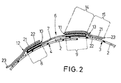
- Fig. 2
- einen schematischen Horizontal-Längsschnitt durch eine Verschlußvorrichtung der Windel entlang der Schnittlinie II-II nach Fig. 1,
- Fig. 3
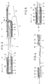
- einen schematischen Horizontal-Längsschnitt einer Verschlußvorrichtung in stark vergrößertem Maßstab,
- Fig. 4
- einen schematischen Horizontal-Längsschnitt durch eine erfindungsgemäße Verschlußvorrichtung, welcher Längsschnitt eine zweite und dritte Ausführungsform zeigt, und
- Fig. 5
- einen teilweisen, schematischen Horizontal-Längsschnitt einer vierten Ausführungsform der Erfindung.
- Fig. 1
- 1 shows a perspective view of an incontinence diaper for adults with a closure device according to the invention in the closed position,
- Fig. 2
- 2 shows a schematic horizontal longitudinal section through a closure device of the diaper along the section line II-II according to FIG. 1,
- Fig. 3
- a schematic horizontal longitudinal section of a closure device on a greatly enlarged scale,
- Fig. 4
- a schematic horizontal longitudinal section through a closure device according to the invention, which longitudinal section shows a second and third embodiment, and
- Fig. 5
- a partial, schematic horizontal longitudinal section of a fourth embodiment of the invention.
Die in Fig. 1 dargestellte Inkontinenzwindel 1 weist einen üblichen, nicht näher dargestellten Windelaufbau mit einem Zellstoff-Flocken-Saugkörper, einer körperseitigen Vliesstoffauflage und einer dem Körper abgewandten, flüssigkeitsundurchlässigen Abdecklage 2 aus dünner Polyethylen-Folie auf. Das Hinterteil 3 und das Vorderteil 4 der Inkontinenzwindel 1 überlappen einander im angelegten Zustand der Windel und bilden dabei Beinöffnungen 5.The
Vorder- 4 und Hinterteil 3 sind durch Verschlußvorrichtungen 6 im Bereich der Hüftaußenseiten miteinander verbunden. Diese Verschlußvorrichtung 6 besteht im wesentlichen aus einem langgestreckten, elastischen Band 7, bei dem es sich um ein textiles Band aus Polyester-Fäden mit eingewebten Gummifäden handelt. Wie aus den Fig. 2 und 3 deutlicher hervorgeht weist das elastische Band 7 in seinen beiden Endbereichen 8,9 beidseitig eine versteifende, das elastische Band 7 unelastisch machende Auflage 10,11 auf, die jeweils als Befestigungsbasis für Selbstklebestreifen 12,13 dienen. Letztere sind mit ihrer einen Längshälfte 14 mit der Auflage 10 bzw. 11 verbunden und mit der zweiten Längshälfte 15 im angelegten Zustand mit der Abdecklage 2 der Windel 1 verklebt.Front 4 and
Aufgrund der vorstehend geschilderten Ausgestaltung der Verschlußvorrichtung 6 wird einerseits eine zuverlässige Fixierung der beiden Windelteile 3,4 zueinander erzielt. Andererseits kann sich die Windel 1 durch die Elastizität des Bandes 7 zwischen den beiden Endbereichen 8,9 optimal an den Träger des Körpers anpassen und auch bei Bewegungen des Trägers einen einwandfreien Sitz der Windel gewährleisten.Because of the above-described configuration of the
Eine bevorzugte Ausführungsform einer erfindungsgemäßem Verschlußvorrichtung 6 ist anhand von Fig. 3 näher zu erläutern. Hierbei bestehen die beiden Auflagen 10,11 in den beiden Endbereichen 8,9 des Bandes 7 jeweils aus einem rechteckigen Kunststoff-Folienstreifen 16 aus einer nicht-dehnbaren Polyesterfolie mit einer Dicke von 125 µm. Die Streifen 16 sind jeweils mittels einer Klebeschicht 17 aus einem wärmeaktivierbaren Polyester-Schmelzkleber in den Endbereichen 8,9 des Bandes 7 mit diesem verklebt. Dabei werden die Streifen 16 so aufgebracht, daß sie sich von einer Längsseite 18 des elastischen Bandes 7 um das Bandende 19 herum auf die zweite Längsseite 20 erstrecken. Wie durch eine verdickte Linie in Fig. 3 angedeutet ist, weist der Kunststoff-Folienstreifen 16 auf der im angelegten Zustand der Windel zugekehrten Seite - also auf der der Längsseite 18 des elastischen Bandes 7 zugewandten Seite - eine Beschichtung 29 in Form einer Silikonisierung auf. Durch diese Beschichtung 29 haften die Selbstklebestreifen 12, 13 in diesen Bereich weniger als auf dem unbeschichteten Teil der Kunststoff-Folienstreifen 16. Dadurch können die Selbstklebestreifen 12, 13 leichter von dieser Seite der Auflagen 10, 11 abgezogen werden. Damit ist die Handhabung des erfindungsgemäßen Windel-Verschlußsystems weiter vereinfacht.A preferred embodiment of a
Bei der Anbringung der Auflagen 10,11 wird dabei so verfahren, daß eine Bahn der Polyesterfolie mittels eines Rotationsschmelzsiebdruck-Verfahrens mit der Klebeschicht 17 versehen wird. Dabei kommt ein Sieb mit einer Maschenweite von 11 mesh zum Einsatz, mit dem der Klebstoff mit einem Auftragsgewicht von 50 g/m² unter Bildung kleiner Noppen aufgebracht wird. Die derart beschichtete Bahn wird zu Streifen 16 geschnitten, die wie in Fig. 3 dargestellt, in ungedehntem Zustand des Bandes 7 um dessen Endbereiche 8,9 herumgelegt werden. Anschließend werden die Streifen 16 durch Pressen und Temperatureinwirkung beidseitig aufgebügelt, so daß ein fester Verbund der Streifen 16 mit dem Band 7 in den Endbereichen 8,9 entsteht. Durch diesen festen Verbund ist das elastische Band in den Endbereichen 8,9 nicht mehr dehnbar. Damit können die Auflagen 10, 11 als stabiler Untergrund für die Anbringung eines Klebeelements zur Verbindung des Bandes 7 mit der Windel 1 dienen.When the
Die anhand Fig. 1 allgemein angesprochenen Selbstklebestreifen 12,13 bestehen aus einem streifenförmigen imprägnierten Papierträger 21, der auf einer Seite mit einer Beschichtung 22 aus einer selbstklebenden Heißschmelzkleber-Masse auf der Basis von Styrol-Isopren-Styrol-Blockcopolymeren versehen ist. Die Beschichtung 22 ist mit Hilfe eines Rotationsschmelzsiebdruckverfahrens mittels eines 25 mesh-Siebes und mit einem Auftragsgewicht von 35 g/m² aufgebracht.The self-
Wie aus Fig. 3 deutlich wird, können die Selbstklebestreifen 12,13 in einem Lagerzustand mit ihrer vollen Länge auf den Auflagen 10,11 aufgeklebt sein (siehe Fig. 3, linker Teil), wodurch letztere als Release-Tape wirken.As is clear from FIG. 3, the self-
Bei Verwendung der Verschlußvorrichtung 6 beim Anlegen der Windel 1 werden die Selbstklebestreifen 12,13 zur Hälfte abgezogen, was durch das von der Beschichtung 22 freibleibende Griffende 23 an den Klebestreifen 12,13 erleichtert wird. Die von der Auflage 10,11 abgezogene Längshälfte 15 wird anschließend auf die Abdecklage 2 der Windel 1 aufgedrückt und somit verklebt (s. Fig. 2 sowie Fig. 3, rechter Teil). Diese Verklebung ist aufgrund der Beschaffenheit und noppenförmigen Ausgestaltung der Beschichtung 22 reversibel lösbar, so daß der Selbstklebestreifen 12,13 von einer verbrauchten Windel 1 abgezogen und die gesamte Verschlußvorrichtung 6 bei einer neuen Windel wiederverwendbar ist. Bis zur Wiederverwendung können die Selbstklebestreifen 12,13 auf den Auflagen 10,11, wie in Fig. 3, linker Teil dargestellt, zwischengelagert werden. Weiterhin können nach einer vielfachen Benutzung der Selbstklebestreifen 12,13 und einem entsprechenden Nachlassen der Klebekraft die Selbstklebestreifen 12, 13 im Bereich ihrer Längshälften 14 von den Auflagen 10,11 komplett abgezogen und neue Klebestreifen aufgebracht werden.When using the
Im übrigen wird zum Herstellungsverfahren der Beschichtung 22 bzw. der Klebeschicht 17 auf die deutsche Patentanmeldung P 42 02 704.7 verwiesen, in der das verwendete Rotationsschmelzsiebdruckverfahren eingehend erörtert ist.For the rest, reference is made to the German patent application P 42 02 704.7 for the production process of the
Bei dem in Fig. 4, rechter Teil gezeigten Ausführungsbeispiel einer Verschlußvorrichtung 6' ist wiederum ein elastisches Band 7' vorhanden, das in seinen beiden Endbereichen 9' auf einer Seite mit einer Auflage 11' versehen ist, die aus einer thermoplastischen Beschichtung 24 auf einer Längsseite 18' des Bandes besteht. Die Beschichtung 24 wird beispielsweise durch Angießen eines geschmolzenen thermoplastischen Kunststoffes hergestellt, der sich innig mit der Textilstruktur des elastischen Bandes 7' verbindet und nach dem Erkalten fest mit dem elastischen Band 7' verankert ist. Auf ihrer Oberseite ist die Beschichtung 24 wiederum mit einer aus kleinen Noppen gebildeten Klebeschicht 25 versehen, die mit Hilfe des bereits erwähnten Rotationsschmelzsiebdruckverfahrens aufgebracht wird. Damit kann die Verschlußvorrichtung 6' wiederum reversibel lösbar mit einer Windel 1 verbunden werden.In the embodiment shown in FIG. 4, right part of a closure device 6 ', there is again an elastic band 7', which is provided in its two end regions 9 'on one side with a support 11' made of a
In Fig. 4, linker Teil ist ein Ausführungsbeispiel einer Verschlußvorrichtung 6'' gezeigt, bei dem die grundsätzliche Machart der das Gummiband 7'' unelastisch machenden Auflage 10' dem Ausführungsbeispiel gemäß Fig. 3 entspricht. Dabei ist ein Stanzling auf der Basis eines imprägnierten Papierstreifens 26 vorgesehen, der auf seiner Außenseite mit der bereits erwähnten noppenförmigen Klebeschicht 25' aus selbstklebendem Klebstoff versehen ist. Diese Klebeschicht 25' ist wiederum mit dem bereits erwähnte Rotationsschmelzsiebdruckverfahren aufzubringen. Auf der Innenseite des Papierstreifens 26 ist eine permanent selbstklebende Klebeschicht 27 vorgesehen, mit der der Papierstreifen 26 dauerhaft mit dem elastischen Band 7'' verbunden wird. Durch diese feste Verbindung ist der Endbereich 8' wiederum unelastisch gemacht. Die Innenseite des Papierstreifens 26 kann im übrigen auch mit einer wärmeaktivierbaren Klebeschicht beschichtet werden, wobei durch ein Schmelzen des Klebers die permanente Verbindung hergestellt wird.4, left part, an embodiment of a
Bei beiden Ausführungsformen gemäß Fig. 4 ist auf der Klebeschicht 25, 25' ein Abdeckstreifen 28 aus silikonisiertem Papier aufgebracht, der vor Einsatz der Verschlußvorrichtung 6' bzw. 6'' zum Freilegen der Klebeschicht 25, 25'' abgezogen wird.In both embodiments according to FIG. 4, a
Das in Fig. 5 gezeigte Ausführungsbeispiel entspricht im wesentlichen dem Ausführungsbeispiel gemäß Fig. 3. Übereinstimmende Teile sind daher mit übereinstimmenden Bezugszeichen versehen. Als Unterschied ist jedoch der Kunststoff-Folienstreifen 16' nicht um das Bandende 19 herumgezogen, sondern nur im Bereich der außenseitigen Längsseite 20 angebracht. Es handelt sich dabei um einen unbeschichteten Polyester-Folienstreifen, auf dem der Selbstklebestreifen 13 sehr gut haftet. Auf der innenseitigen Längsseite 18 ist ein Papierstreifen 26' über die Klebeschicht 17 aufgebracht, der auf seiner Außenseite wiederum eine Beschichtung 29 in Form einer Silikonisierung aufweist. Damit läßt sich der Selbstklebestreifen 13 leichtgängig aus der in Fig. 5 gezeigten "Zwischenlagerstellung" von dem Papierstreifen 26' ablösen und in die in Fig. 3, rechter Teil gezeigte Aktivstellung verbringen.The exemplary embodiment shown in FIG. 5 essentially corresponds to the exemplary embodiment according to FIG. 3. Corresponding parts are therefore provided with the same reference numerals. As a difference, however, the plastic film strip 16 'is not drawn around the
Claims (12)
das mindestens eine Verbindungselement eine das elastische Band (7,7') in einem Teilbereich versteifende, unelastisch machende Auflage (10,11, 10',11') aufweist, an der ein Selbstklebeelement (Selbstklebestreifen 12,13, Klebeschicht 25) zur reversibel lösbaren Verbindung des Bandes (7) mit dem Artikel (Inkontinenzwindel 1) angebracht ist.Closure device for hygiene articles, such as incontinence diapers, children's panties, incontinence pads or the like, for connecting two parts of the hygiene article, in particular diaper closure for connecting a front (4) and rear part (3) of a diaper (1) in the area of the outside of the hips
the at least one connecting element has a non-elastic covering (10, 11, 10 ', 11') which stiffens the elastic band (7,7 ') in a partial area and on which a self-adhesive element (self-adhesive strip 12, 13, adhesive layer 25) is reversible Detachable connection of the band (7) with the article (incontinence diaper 1) is attached.
Applications Claiming Priority (2)
| Application Number | Priority Date | Filing Date | Title |
|---|---|---|---|
| DE4327589 | 1993-08-17 | ||
| DE4327589A DE4327589A1 (en) | 1993-08-17 | 1993-08-17 | Closure device for hygiene articles, in particular diaper closure |
Publications (3)
| Publication Number | Publication Date |
|---|---|
| EP0640331A2 true EP0640331A2 (en) | 1995-03-01 |
| EP0640331A3 EP0640331A3 (en) | 1995-06-14 |
| EP0640331B1 EP0640331B1 (en) | 1999-10-20 |
Family
ID=6495357
Family Applications (1)
| Application Number | Title | Priority Date | Filing Date |
|---|---|---|---|
| EP94112557A Expired - Lifetime EP0640331B1 (en) | 1993-08-17 | 1994-08-11 | Closure device for hygienic articles, particularly diaper closure |
Country Status (3)
| Country | Link |
|---|---|
| EP (1) | EP0640331B1 (en) |
| DE (2) | DE4327589A1 (en) |
| ES (1) | ES2139693T3 (en) |
Cited By (3)
| Publication number | Priority date | Publication date | Assignee | Title |
|---|---|---|---|---|
| US5669901A (en) * | 1996-04-18 | 1997-09-23 | Kimberly-Clark Worldwide, Inc. | Absorbent article having an improved mechanical fastening system |
| US5704933A (en) * | 1996-04-18 | 1998-01-06 | Kimberly-Clark Worldwide, Inc. | Elastic strap fastening system with button fasteners |
| WO2003086260A1 (en) * | 2002-04-12 | 2003-10-23 | 3M Innovative Properties Company | Elastic closure tab |
Citations (2)
| Publication number | Priority date | Publication date | Assignee | Title |
|---|---|---|---|---|
| FR2137855A1 (en) | 1971-05-12 | 1972-12-29 | Jacob Ezekiel | |
| WO1981003601A1 (en) | 1980-06-19 | 1981-12-24 | Beghin Say Sa | Elastic fastener for pilch |
Family Cites Families (8)
| Publication number | Priority date | Publication date | Assignee | Title |
|---|---|---|---|---|
| US2931747A (en) * | 1957-02-11 | 1960-04-05 | Fred F Dexter | Fabric fastener |
| US4074716A (en) * | 1977-01-03 | 1978-02-21 | Colgate-Palmolive Company | Diaper with elastic fastener tab |
| FR2403036A1 (en) * | 1977-09-16 | 1979-04-13 | Celatose Sa | Elastic adhesive straps for securing baby pants - to accommodate temporary variation in the girth of the wearer |
| DE8212480U1 (en) * | 1982-04-30 | 1982-08-05 | Beiersdorf Ag, 2000 Hamburg | ELASTIC PERSONAL DIAPER CLOSURE |
| EP0191355B1 (en) * | 1985-01-30 | 1989-04-19 | Kao Corporation | A fastener tape for disposable diaper |
| JPS6350807U (en) * | 1986-09-24 | 1988-04-06 | ||
| DE3710037A1 (en) * | 1987-03-30 | 1988-10-20 | Koester Kg | Adhesive tape for closing nappy pants, nappy pants and method for the manufacture thereof |
| DE4202704C2 (en) * | 1992-01-31 | 1994-12-01 | Schickedanz Ver Papierwerk | Pant diaper with self-adhesive closure system and process for its manufacture and its use |
-
1993
- 1993-08-17 DE DE4327589A patent/DE4327589A1/en not_active Withdrawn
-
1994
- 1994-08-11 ES ES94112557T patent/ES2139693T3/en not_active Expired - Lifetime
- 1994-08-11 EP EP94112557A patent/EP0640331B1/en not_active Expired - Lifetime
- 1994-08-11 DE DE59408837T patent/DE59408837D1/en not_active Expired - Lifetime
Patent Citations (2)
| Publication number | Priority date | Publication date | Assignee | Title |
|---|---|---|---|---|
| FR2137855A1 (en) | 1971-05-12 | 1972-12-29 | Jacob Ezekiel | |
| WO1981003601A1 (en) | 1980-06-19 | 1981-12-24 | Beghin Say Sa | Elastic fastener for pilch |
Cited By (3)
| Publication number | Priority date | Publication date | Assignee | Title |
|---|---|---|---|---|
| US5669901A (en) * | 1996-04-18 | 1997-09-23 | Kimberly-Clark Worldwide, Inc. | Absorbent article having an improved mechanical fastening system |
| US5704933A (en) * | 1996-04-18 | 1998-01-06 | Kimberly-Clark Worldwide, Inc. | Elastic strap fastening system with button fasteners |
| WO2003086260A1 (en) * | 2002-04-12 | 2003-10-23 | 3M Innovative Properties Company | Elastic closure tab |
Also Published As
| Publication number | Publication date |
|---|---|
| DE59408837D1 (en) | 1999-11-25 |
| DE4327589A1 (en) | 1995-02-23 |
| EP0640331A3 (en) | 1995-06-14 |
| EP0640331B1 (en) | 1999-10-20 |
| ES2139693T3 (en) | 2000-02-16 |
Similar Documents
| Publication | Publication Date | Title |
|---|---|---|
| EP0951266B1 (en) | Single use hygiene article with combined mechanic and adhesive closing system | |
| DE2430881C2 (en) | Disposable diaper with fastening system | |
| DE69511105T3 (en) | MULTILAYER CLOSING SYSTEM | |
| DE2856869C2 (en) | Adhesive tape fastener for a disposable diaper pant and method of making the adhesive tape fastener | |
| DE2644313C2 (en) | Disposable diaper | |
| DE69831291T2 (en) | Disposable absorbent garment with an adhesive strip for disposal | |
| DE60112823T2 (en) | Disposable diaper for dressing | |
| EP0994689B1 (en) | Disposable hygienic article | |
| DE10140622A1 (en) | Hygiene articles with fastening elements | |
| EP1853209B1 (en) | Film dressing comprising an application aid | |
| DE2418209A1 (en) | ADHESIVE CLOSURE FOR HOOK DIAPERS | |
| DE60010339T3 (en) | WINDEL MOUNTING WITH PERFORATED SCRAPING LINE | |
| DE60308007T2 (en) | WINDEL OF THE ONE-WAY HOSPY TYPE AND METHOD OF MANUFACTURING THEREOF | |
| EP0656769B1 (en) | Breast prosthesis | |
| EP0780109B1 (en) | Diaper closure tape | |
| DE19727916C2 (en) | Disposable hygiene items | |
| DE60113590T2 (en) | Disposable underwear | |
| DE60317754T2 (en) | Absorbent articles with flaky fibers | |
| EP0640331B1 (en) | Closure device for hygienic articles, particularly diaper closure | |
| DE112019005079T5 (en) | Disposable diaper | |
| DE60119391T2 (en) | MECHANICAL TAPE FASTENING SYSTEM FOR PURIFYABLE DISPOSABLE ARTICLES | |
| EP0832630B1 (en) | Diaper fastening tape | |
| DE2854792C2 (en) | Diaper pants or the like. | |
| DE112019005082T5 (en) | Disposable diaper | |
| EP0793953A2 (en) | Disposable diaper and its method of manufacturing |
Legal Events
| Date | Code | Title | Description |
|---|---|---|---|
| PUAI | Public reference made under article 153(3) epc to a published international application that has entered the european phase |
Free format text: ORIGINAL CODE: 0009012 |
|
| AK | Designated contracting states |
Kind code of ref document: A2 Designated state(s): DE ES FR GB IT NL SE |
|
| PUAL | Search report despatched |
Free format text: ORIGINAL CODE: 0009013 |
|
| AK | Designated contracting states |
Kind code of ref document: A3 Designated state(s): DE ES FR GB IT NL SE |
|
| 17P | Request for examination filed |
Effective date: 19951114 |
|
| RAP1 | Party data changed (applicant data changed or rights of an application transferred) |
Owner name: THE PROCTER & GAMBLE COMPANY |
|
| 17Q | First examination report despatched |
Effective date: 19961205 |
|
| GRAG | Despatch of communication of intention to grant |
Free format text: ORIGINAL CODE: EPIDOS AGRA |
|
| GRAG | Despatch of communication of intention to grant |
Free format text: ORIGINAL CODE: EPIDOS AGRA |
|
| GRAH | Despatch of communication of intention to grant a patent |
Free format text: ORIGINAL CODE: EPIDOS IGRA |
|
| GRAH | Despatch of communication of intention to grant a patent |
Free format text: ORIGINAL CODE: EPIDOS IGRA |
|
| GRAA | (expected) grant |
Free format text: ORIGINAL CODE: 0009210 |
|
| AK | Designated contracting states |
Kind code of ref document: B1 Designated state(s): DE ES FR GB IT NL SE |
|
| REF | Corresponds to: |
Ref document number: 59408837 Country of ref document: DE Date of ref document: 19991125 |
|
| ITF | It: translation for a ep patent filed |
Owner name: ING. C. GREGORJ S.P.A. |
|
| ITF | It: translation for a ep patent filed |
Owner name: STUDIO TORTA S.R.L. |
|
| ET | Fr: translation filed | ||
| GBT | Gb: translation of ep patent filed (gb section 77(6)(a)/1977) |
Effective date: 20000114 |
|
| REG | Reference to a national code |
Ref country code: ES Ref legal event code: FG2A Ref document number: 2139693 Country of ref document: ES Kind code of ref document: T3 |
|
| PLBE | No opposition filed within time limit |
Free format text: ORIGINAL CODE: 0009261 |
|
| STAA | Information on the status of an ep patent application or granted ep patent |
Free format text: STATUS: NO OPPOSITION FILED WITHIN TIME LIMIT |
|
| 26N | No opposition filed | ||
| REG | Reference to a national code |
Ref country code: GB Ref legal event code: IF02 |
|
| PGFP | Annual fee paid to national office [announced via postgrant information from national office to epo] |
Ref country code: NL Payment date: 20080715 Year of fee payment: 15 Ref country code: ES Payment date: 20080808 Year of fee payment: 15 |
|
| PGFP | Annual fee paid to national office [announced via postgrant information from national office to epo] |
Ref country code: IT Payment date: 20080816 Year of fee payment: 15 |
|
| PGFP | Annual fee paid to national office [announced via postgrant information from national office to epo] |
Ref country code: SE Payment date: 20080808 Year of fee payment: 15 |
|
| REG | Reference to a national code |
Ref country code: NL Ref legal event code: V1 Effective date: 20100301 |
|
| PG25 | Lapsed in a contracting state [announced via postgrant information from national office to epo] |
Ref country code: NL Free format text: LAPSE BECAUSE OF NON-PAYMENT OF DUE FEES Effective date: 20100301 |
|
| REG | Reference to a national code |
Ref country code: ES Ref legal event code: FD2A Effective date: 20090812 |
|
| PG25 | Lapsed in a contracting state [announced via postgrant information from national office to epo] |
Ref country code: IT Free format text: LAPSE BECAUSE OF NON-PAYMENT OF DUE FEES Effective date: 20090811 |
|
| PG25 | Lapsed in a contracting state [announced via postgrant information from national office to epo] |
Ref country code: SE Free format text: LAPSE BECAUSE OF NON-PAYMENT OF DUE FEES Effective date: 20090812 |
|
| PG25 | Lapsed in a contracting state [announced via postgrant information from national office to epo] |
Ref country code: ES Free format text: LAPSE BECAUSE OF NON-PAYMENT OF DUE FEES Effective date: 20090812 |
|
| PGFP | Annual fee paid to national office [announced via postgrant information from national office to epo] |
Ref country code: DE Payment date: 20130902 Year of fee payment: 20 |
|
| PGFP | Annual fee paid to national office [announced via postgrant information from national office to epo] |
Ref country code: FR Payment date: 20130725 Year of fee payment: 20 Ref country code: GB Payment date: 20130726 Year of fee payment: 20 |
|
| REG | Reference to a national code |
Ref country code: DE Ref legal event code: R071 Ref document number: 59408837 Country of ref document: DE |
|
| REG | Reference to a national code |
Ref country code: GB Ref legal event code: PE20 Expiry date: 20140810 |
|
| PG25 | Lapsed in a contracting state [announced via postgrant information from national office to epo] |
Ref country code: DE Free format text: LAPSE BECAUSE OF EXPIRATION OF PROTECTION Effective date: 20140812 |
|
| PG25 | Lapsed in a contracting state [announced via postgrant information from national office to epo] |
Ref country code: GB Free format text: LAPSE BECAUSE OF EXPIRATION OF PROTECTION Effective date: 20140810 |