EP0640903A1 - A driver assistance system for a vehicle - Google Patents
A driver assistance system for a vehicle Download PDFInfo
- Publication number
- EP0640903A1 EP0640903A1 EP94306371A EP94306371A EP0640903A1 EP 0640903 A1 EP0640903 A1 EP 0640903A1 EP 94306371 A EP94306371 A EP 94306371A EP 94306371 A EP94306371 A EP 94306371A EP 0640903 A1 EP0640903 A1 EP 0640903A1
- Authority
- EP
- European Patent Office
- Prior art keywords
- lane
- vehicle
- steering
- driver
- torque
- Prior art date
- Legal status (The legal status is an assumption and is not a legal conclusion. Google has not performed a legal analysis and makes no representation as to the accuracy of the status listed.)
- Granted
Links
Images


Classifications
-
- B—PERFORMING OPERATIONS; TRANSPORTING
- B62—LAND VEHICLES FOR TRAVELLING OTHERWISE THAN ON RAILS
- B62D—MOTOR VEHICLES; TRAILERS
- B62D15/00—Steering not otherwise provided for
- B62D15/02—Steering position indicators ; Steering position determination; Steering aids
- B62D15/025—Active steering aids, e.g. helping the driver by actively influencing the steering system after environment evaluation
-
- G—PHYSICS
- G05—CONTROLLING; REGULATING
- G05D—SYSTEMS FOR CONTROLLING OR REGULATING NON-ELECTRIC VARIABLES
- G05D1/00—Control of position, course or altitude of land, water, air, or space vehicles, e.g. automatic pilot
- G05D1/02—Control of position or course in two dimensions
- G05D1/021—Control of position or course in two dimensions specially adapted to land vehicles
- G05D1/0231—Control of position or course in two dimensions specially adapted to land vehicles using optical position detecting means
- G05D1/0246—Control of position or course in two dimensions specially adapted to land vehicles using optical position detecting means using a video camera in combination with image processing means
-
- B—PERFORMING OPERATIONS; TRANSPORTING
- B60—VEHICLES IN GENERAL
- B60T—VEHICLE BRAKE CONTROL SYSTEMS OR PARTS THEREOF; BRAKE CONTROL SYSTEMS OR PARTS THEREOF, IN GENERAL; ARRANGEMENT OF BRAKING ELEMENTS ON VEHICLES IN GENERAL; PORTABLE DEVICES FOR PREVENTING UNWANTED MOVEMENT OF VEHICLES; VEHICLE MODIFICATIONS TO FACILITATE COOLING OF BRAKES
- B60T2201/00—Particular use of vehicle brake systems; Special systems using also the brakes; Special software modules within the brake system controller
- B60T2201/08—Lane monitoring; Lane Keeping Systems
- B60T2201/087—Lane monitoring; Lane Keeping Systems using active steering actuation
-
- B—PERFORMING OPERATIONS; TRANSPORTING
- B60—VEHICLES IN GENERAL
- B60W—CONJOINT CONTROL OF VEHICLE SUB-UNITS OF DIFFERENT TYPE OR DIFFERENT FUNCTION; CONTROL SYSTEMS SPECIALLY ADAPTED FOR HYBRID VEHICLES; ROAD VEHICLE DRIVE CONTROL SYSTEMS FOR PURPOSES NOT RELATED TO THE CONTROL OF A PARTICULAR SUB-UNIT
- B60W2540/00—Input parameters relating to occupants
- B60W2540/18—Steering angle
-
- G—PHYSICS
- G05—CONTROLLING; REGULATING
- G05D—SYSTEMS FOR CONTROLLING OR REGULATING NON-ELECTRIC VARIABLES
- G05D1/00—Control of position, course or altitude of land, water, air, or space vehicles, e.g. automatic pilot
- G05D1/02—Control of position or course in two dimensions
- G05D1/021—Control of position or course in two dimensions specially adapted to land vehicles
- G05D1/0231—Control of position or course in two dimensions specially adapted to land vehicles using optical position detecting means
- G05D1/0242—Control of position or course in two dimensions specially adapted to land vehicles using optical position detecting means using non-visible light signals, e.g. IR or UV signals
-
- G—PHYSICS
- G05—CONTROLLING; REGULATING
- G05D—SYSTEMS FOR CONTROLLING OR REGULATING NON-ELECTRIC VARIABLES
- G05D1/00—Control of position, course or altitude of land, water, air, or space vehicles, e.g. automatic pilot
- G05D1/02—Control of position or course in two dimensions
- G05D1/021—Control of position or course in two dimensions specially adapted to land vehicles
- G05D1/0255—Control of position or course in two dimensions specially adapted to land vehicles using acoustic signals, e.g. ultra-sonic singals
Definitions
- This invention relates generally to a driver assistance system for a vehicle adapted to control the direction of a moving vehicle along a predetermined path.
- EP-A-0 514 343 discloses an automatic lateral guidance control system for guiding moving vehicles.
- the system includes a sensing subsystem for viewing an area in front of a vehicle, a plurality of energy radiating or energy reflective devices disposed adjacent a predetermined length of road, an apparatus for translating the radiating or reflected information from the viewed area into co-ordinate data representing an approximation of the predetermined path along the road, and a vehicle controller for determining the vehicle's heading with respect to the approximated path and providing an output control signal to correct the vehicle's heading with respect to the approximated path.
- the system uses past and present position data to calculate a predetermined path for the vehicle. Gain factors and comfort factors are determined to maximise comfort for passengers of the system and to optimise performance of the system.
- the automatic guidance control system of EP-A-0 514 343 is adapted to control the direction of a moving vehicle without the need for human intervention and the system is more responsive than the control provided by the operator of the vehicle.
- a method of tracking a contrived centre line between lane markings of a road characterised in that a steering bias is applied to the steering system of the vehicle in such a manner as to assist the driver in tracking the contrived centre line position.
- the contrived centre line may be the true centre line between lane markings, for example on a motorway, or may be offset from the true centre line, for example to facilitate the negotiation of curves or bends when the contrived centre line comprises a more economical tracing a line.
- the level of steering bias applied to the steering system is relatively small when the track of the vehicle is in proximity to the contrived centre line proximity and the steering bias is adapted to be increased as the vehicle approaches the boundaries defined by the lane markings.
- a steering torque ripple is applied to the steering system as the vehicle approaches a lane boundary.
- an audio signal may be produced to alert the driver of possible lane boundary infringement.
- the audio signal may simulate that of a "rumble” strip crossing or that of crossing "cats eyes”.
- the frequency of the audio signal may be proportional or varied in some way according to the velocity of the vehicle and may be arranged to be produced so as to appear from the area of infringement.
- the conventional audio system of the vehicle may be utilised to produce the simulated infringement signal.
- the conventional audio system may be inhibited during infringement signal simulation or it may be blended with the conventional audio signal output.
- the system If the lane marking signals are lost, a warning is issued to the driver and the system is disabled. Should the lane marking signals be lost due to masking of the signals by a preceding vehicle then the system adopts a vehicle tracking approach until the lane marking signal is re-established.
- This system incorporates means for cancelling the signal bias when a direction indicator of the vehicle is actuated. Preferably only that steering bias in the direction of indication is cancelled and steering bias is still applied in the opposite direction of movement of the vehicle with respect to the contrived centre line.
- the steering bias is adapted to be applied to the steering system by the use of an electrically operated device, such as an electric motor, which co-operates with the existing, conventional, steering system of the vehicle, which may be power assisted.
- an electrically operated device such as an electric motor
- the lane markings may be detected by the use of a video camera or equivalent sensor mounted on the vehicle which is "light sensitive” or of the "infra-red” sensing type.
- An associated signal processor estimates the lateral position of the vehicle in relation to the lane markings.
- An electric motor coupled to the steering mechanism is used to provide a torque input to the steering system, which may either assist or oppose the steering torque from the driver.
- the motor is designed to assist the driver in maintaining the position of the vehicle with respect to the lane markings by holding it at a set point using a biasing torque in accordance with signals from the signal processor. This simulates the effect of the lane being cambered upwards towards the lane edges, defined by the lane markings. However the driver is able to over-ride or cancel the effect if the steering torque applied to the steering system by the driver exceeds a predetermined torque threshold.
- the driver has ultimate control over the vehicle and can over-ride the bias force by virtue of steering wheel torque sensor inputs.
- the system supplements the existing power steering mechanism whilst also providing a failure back-up in the event of engine stall or pump drive belt failure.
- the electric motor is coupled to the steering mechanism through a gearbox and, possibly also, a clutch.
- a torque sensor positioned between the steering wheel and the electric motor is adapted to detect the steering effort provided by the driver.
- the torque sensor typically comprises a compliant element in the steering column shaft whose angle and direction of twist are measured either optically or inductively.
- the driver assistance system can also be used as a back-up to the conventional power assisted steering system so that some steering assistance is still available in the event of engine failure, failure of the belt drive to the power steering pump, or other problem.
- the driver assistance system could be provided as a part of an EPAS (electronic power assisted steering) unit with similar back-up provisions in case of emergency.
- the system could be provided as a unit added to steering systems previously having no power assisted steering.
- our invention acts as a lane support system to provide greater comfort to the driver, improved steering stability, and safety.
- a method of collision avoidance for a vehicle comprising:
- Threatening obstacles may be other vehicles which are or are likely to intrude in the space required for the lateral movement due to the respective vehicles velocities, or they may be immobile objects such as barriers, wreckages, or the like, or even particular patterns of markings on the road surface, such as the double lines commonly signifying no overtaking.
- the system may be overridden by the vehicles driver.
- the override may consist of ignoring the warning or applying sufficient torque to overcome the steering bias applied by the system.
- the lateral movement comprises movement from a position in which the vehicle tracks a first contrived centre line between lane markings of a road and a position where he vehicle tracks a second contrived centre line between lane markings defining another lane of a road.
- the second contrive centre line is a lane adjacent to that of the first contrived centre line.
- a safe method for changing lanes on a road can be provided, or even for leaving or joining a road by means of a slip road.
- the system may even extend to velocity control to provide a safe envelope into which the vehicle can move.
- the means for deterring lateral movement may comprise any one or more of an audible or visual warning to the driver of the vehicle, a vibration applied to the steering system, or a steering bias applied to the steering system to resist any torque applied so as to cause the undesired lateral movement, such as may be applied by the driver.
- the lateral movement is sought automatically in response to the driver indicating a desire to move laterally, such as by activating the vehicles directional indicators or other user/system interface.
- the system may apply a steering bias so as to maintain the current lateral position if an obstacle is detected or may apply a steering bias so as to affect the lateral movement if no threatening obstacle is detected.
- Such a system may affect a lane change as soon as possible, after its request, delaying the change for as long as necessary to ensure safe movement.
- the monitoring may be restricted to the side and rear of a vehicle and is preferably restricted to the road's lanes.
- Monitoring may be continuous or may be activated upon requires or indication of a lane change, or by approach to the edge of a lane.
- Electromagnetic wave eg visual, radar, or other forms of monitoring may be used.
- Apparatus for avoiding vehicular collision comprising:
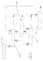
- the lane support system illustrated in the layout of Figure 1 is adapted for use with a conventional steering system 1 of a vehicle.
- the conventional steering system comprises a steering rack 2 for controlling the steering position of the front wheels of a vehicle in response to manual operation of a steering wheel 3.
- An electrically operated motor 4 is adapted to provide servo or power assistance to augment the steering effort applied to the rack 2 from the steering wheel 3 in response to an energising current from an electronic control unit 5, in turn responsive to signals from a torque sensor 6, such as disclosed in EP 0 555 987, comprising a compliant element in the shaft of the steering column 7 whose angle and direction of twist are measured either optically or inductively.
- the electric motor 4 is coupled to the steering mechanism through a gearbox 8 and a clutch 9 which may be omitted from certain installations.
- the vehicle is provided with a video camera 10 which is mounted on the vehicle, for example in the middle of the bonnet or grille, or in the vicinity of the internal rear-view mirror in order to detect the presence of lane markings on a road, for example the spaced white or yellow lines defining a lane of a motorway.
- the video camera 10 may be "light-sensitive" or of the "infra-red” sensing type. Such systems are disclosed in a technical paper presented to the IEE in October 1992 entitled “Imposed Obstacle Detection By Sensor Fusion".
- a signal image processor 11 in response to signals from the video camera 10, estimates the lateral position of the vehicle in relation to the lane markings.
- Corresponding signals from the signal processor 11 are fed into the electronic control unit 5 which is then operative to energise the motor 4 to apply a torque to the steering shaft to independently assist the driver in maintaining the position of the vehicle with respect to the lane markings by holding it at a set point by the development of an appropriate biasing torque.
- the electronic control unit 5 also receives signals from, and transmits signals to, a driver interface 12 illustrated in Figure 4 of the accompanying drawings which includes a LCD display 13 and an actuation switch 14.
- the electronic control unit 5 also receives a signal from a road speed sensor 16.
- the video image 22 is used to detect lane markings as represented by block 20 and those detected signals control the motor 4, which in turn controls actuators 21 for operating the steering rack 2.
- the video image is utilised with detector means 23 for detecting the visual time to impact and target status so that all targets can be tracked as represented by block 24 in accordance with the road geometry as represented by block 25, for example discontinuous or disabled lane markings.
- the electronic control unit 5 responds to signals from the image processor 11 and produces signals of greater or lesser magnitude to provide, in turn, a greater or smaller bias to the steering system depending upon the displacement of the vehicle from its contrived center line position.
- This is equivalent to the camber effect described above, but with the addition, as the vehicle approaches a lane boundary, of inducing an artificial rumble strip 15, as shown in Figure 2 to induce or apply a feeling of vibration to the steering wheel, thereby alerting the driver to the proximity of the lane marking.
- the frequency of the vibration may be proportional to the vehicles velocity.
- the steering bias applies by the lane support system can be switched on and off by the use of the switch 14 on the driver interface.
- the system is automatically disabled temporarily when a direction indicator is operated to indicate that the vehicle is moving out of the lane, for example to overtake a vehicle in front.
- This manual lane change, for example to the left is illustrated in Figure 7 with the removal of the artificial camber to the left of the vehicle.
- the system is first switched on by operation of the switch 14 the display 13 indicates that this has occurred.
- the system searches the lane markings. Whilst it is doing this the message on the display 13 reads "searching". As soon as the system locates the lane markings the display 13 displays "accept". If the lane marking is lost the display 13 returns "searching” until it again locates the marking with the display 13 returning to "accept”. As soon as the "accept” message appears the driver then presses "accept” button to activate the lane support system. The message “following” is displayed on the display 13. The system then checks the location of the vehicle by following the contrived centre line and applies a light bias to the steering in order to resist any movement away from the centre line position.
- the driver By turning the steering wheel the driver can resist the bias, but the bias to be resisted increases as the vehicle approaches the lane markings. This provides a sensation of a "feeling" of road camber with the steering bias increasing in accordance with the steepness of the camber.
- audio messages may be issued as the vehicle crosses a lane marking by utilising the conventional audio system of the vehicle.
- the conventional audio system may be inhibited during infringement signal simulation or it may be blended with the conventional audio signal output.
- the driver can cancel the lane support system by operating the switch.
- the system is disabled automatically, or may even be switched off, when the driver drives through a lane or, as described above, the camber resistance is cancelled in one direction when the traffic indicator for movement of the car in that direction is operated.
- the system can simply be switched off or can be placed in the "actuate" mode in which it will be switched off automatically under the conditions described above.
- the lane support system is disabled if lane markings are lost and the interface returns to displaying the "searching" mode, issuing an audible signal to indicate that "search” is taking place.
- the system can be adapted continuously to monitor the outside and/or inside lane, as required, and indicate to the driver when it is clear to change lanes. If it is clear then the car will automatically change lane when the driver presses a lane change button, A or B in Figure 8, or otherwise activates the system and direction indicators may be automatically activated.
- the steering will feel like the camber on a banked bend as the car changes lane and as illustrated in Figure 8.
- Driver override is the same as before.
- This modification would reduce driver stress during lane changing, and achieve greater safety and convenience.
- Monitoring of the outside and inside lane can also be used to maintain the artificially created camber, even after the driver signals and would, therefore, normally disable it, if the desired lane is not clear. Alternatively or additionally the driver may be warned by either steering or audio feedback of the danger.
- a detection system of the type used in the forward view could be utilised, for instance a Doppler effect microwave radar device.
- haptic feedback in the steering wheel is considered more effective than audible warnings although, as described above, audible warnings may also be used alternatively or additionally.
- the system provides position related assistance/resistance in the steering to give an artificial feel of road camber of either side of the lane defined between the two lines. The driver is still expected to steer the vehicle, but experiences the sensation of driving along "the bottom of a bath tub". The system is deactivated by either the use of the indicators or by the driver exceeding the torque-motion input threshold of the steering wheel.
- the provision of the clutch 9 has the advantage of improving the feel by disengaging the motor 4 when no lane support assistance is required.
- the video based support system is adapted to detect vehicles and lane markings up to a distance of 60 metres.
- the low lane image processing acquires images from the miniature CCD camera situated by the internal rear view mirror. Edges are extracted using a dual Sobel convolution mask and intelligent thresholding. The edges are then thinned using Morphological techniques as shown in Figure 9 of the accompanying drawings. The thin edges in the image are then traced by fitting straight lines to them and turn into line vectors, which are then categorised on the basis of angle.
- the horizontal lines are used by car detection algorithm, and some of the non-horizontal by lane marking detection algorithm.
- a rear-end car filter locates cars in the image played by processing the horizontal line patterns. Classification of cars and the calculation of angle are good. Ranges estimated from the road to camber geometry by assuming a flat earth.
- the lateral position error 100 is defined to be the difference between the lateral position of the centre of the car 101 and the lateral position of the centre of the lane 102.
- the error should be positive when a positive change in the steering angle is required to correct the error, i.e. when the car is to the left of the centre of the lane, the error should be positive.
- This signal is provided by the IDS rack.
- the rate of change of lateral position error should be calculated using the difference between the last two available samples of lateral position error that were received from the IDS rack.
- the rate of change should be positive when the lateral position error is increasing.
- curvature is defined to be reciprocal of the "local" radius 103 of a corner, i.e. curvature 1 local radius
- the radius 103 when the road is straight, the radius 103 will be infinite and the curvature will be zero; when the radius 103 is 100m, the curvature will be 0.01m ⁇ 1 or 10km ⁇ 1.
- the local radius 103 is estimated from the IDS rack information.
- curvature signal If the curvature signal is not valid, then the curvature should be set to zero.
- This signal is provided by the IDS rack.
- the heading is defined as the angle 104 between the cars longitudinal axis 105 and the tangent to the lane direction 106, as shown in Figure 10.
- the heading should be zero when the car is travelling parallel to the centre of the lane 107.
- the heading should be positive when the car is heading to the right of the tangent to the lane direction.
- This signal is provided by the IDS rack.
- the lane width 108 is the distance between the 2 lane boundaries 109 measured the by IDS rack.
- the lane width should always be greater or equal to zero.
- This signal is provided by the IDS rack.
- the steer angle should be calculated using a combination of the EPAS column position measurement and the measurement from the column position potentiometer.
- EPAS steer angle estimate f(EPAS column position, EPAS steer angle centre, time)
- the column position potentiometer should be used to obtain a value of absolute column position. To this value an offset should be added which represents how many turns the steering wheel has made to the left or to the right.
- the number of turns should be incremented every time the column position potentiometer wiper reaches the end of its track when the column is turning clockwise.
- the number of turns should be decremented every time the column position potentiometer wiper reaches the end of its track when the column is turning anti-clockwise.
- a "steer angle valid" flag should be set to false.
- the estimate of the steering wheel turn number should be set to zero when the following conditions both hold
- the "steer angle valid" flag can then be set to true and the steer angle can be set using the following procedure.
- steer angle 1 ⁇ 2 (pot steer angle estimate + EPAS steer angle estimate)
- the steering torque difference is the difference between the guiding torque and the driver torque measured by the EPAS column sensor.
- steering torque difference guiding torque - EPAS column torque
- the difference is used for diagnostics and for the lane support controller operating logic.
- the guidance torque demand shall be passed through a limiter which is ramped between 0 and the maximum guidance torque magnitude in the time specified below.
- Initial state Final state Guidance torque change B EPAS on guiding ramp up limit to maximum in 1 sec C guiding EPAS on ramp down limit to zero in 1 sec D guiding suspended ramp down limit to zero in 1 sec E suspended guiding ramp up limit to maximum in 1 sec F suspended EPAS on guidance torque should be zero G EPAS on, guiding, suspended EPAS disengaged fast change to zero guidance torque H EPAS disengaged EPAS on guidance torque should be zero
- the lane support can be suspended temporarily under the conditions given below.
- the lane support controller should switch from the EPAS disengaged to the EPAS on state if all of the following conditions apply: . disengage EPAS flag is set false by monitor program
- Specification Units lane position error engagement threshold m lane position error resume threshold m minimum width threshold m driver torque engagement threshold Nm driver torque disengagement threshold Nm torque difference disengagement threshold Nm column velocity disengagement threshold rev/s column velocity engagement threshold rev/s road curvature engagement threshold m ⁇ 1 road curvature disengagement threshold degrees heading angle disengagement threshold degrees guidance time-out interval s maximum time in suspended state s maximum steering angle threshold degrees
- the control strategy takes the lane position information from the IDS rack and combines it with the vehicle speed to produce an estimate of desired steering wheel position.
- the error between the desired steering wheel position and the actual steering wheel position is passed through a proportional gain and a limit to produce a guidance torque demand.
- a block diagram of the controller is shown in Figure 12.
- the controller is formed from a number of loops.
- the innermost loop is the steering angle control loop 300.
- This loop takes a limited steer angle demand 301 and calculates a steer angle error 308 using the measured steering angle 302.
- the error is then passed through the steer angle gain 303 to give a guidance torque demand 309.
- the guidance torque demand 309 is limited 304 and slew rate limited 305 before being sent to augment the EPAS control torque 306.
- the limits on guidance torque demand 309 and on steer angle demand 301 are varied with vehicle speed.
- the slew rate limit output should be set to zero whenever the guiding state is entered.
- steer angle error LIMIT(steer angle demand)
- steer angle guidance torque demand SLEWLIM(LIMIT(steer angle gain x steer angle error))
- the second loop 310 controls the heading angle.
- the heading demand 311 is limited 312.
- the heading error 313 is calculated from the difference of the limited heading demand 312 and the measured heading 314. The difference is passed through 2 gains.
- the first gain is the vehicle factor 315.
- the second gain is the heading gain 316.
- the heading gain 316 converts the error into the steer angle demand 317.
- the vehicle factor is a single constant that is calibrated from 3 vehicle-dependent parameters: rack ratio, wheel base length and understeer factor.
- heading error LIMIT (heading demand)
- heading steer angle demand heading error x heading gain x vehicle factor
- vehicle factor rack ratio x wheel base/understeer factor
- the outer loop 320 controls the lateral position.
- the lateral position error 321 is first multiplied by the reciprocal of vehicle speed to give a "normalised" position correction heading 322.
- the position correction heading is added to the limited curve balance feedforward 323 to give the heading demand 311.
- vehicle speed reciprocal 1/LIMIT (vehicle speed)
- the curve balance feedforward 323 referred to above is calculated from the produce of the curvature measurement 324 and the vehicle speed 325. This product is passed through the curve balance gain 326 and then limited 327 to give the curve balance feedforward. NB the curve balance heading limit 323 will give to be set to zero if the curvature measurement 324 is not available.
- curve balance heading LIMIT (curvature x vehicle speed x curve correction gain)
- the limits on guidance torque demand and on steer angle demands are determined by ranges relating to vehicle speed.
- the automatic lane change function senses the turn signal to change lane and uses a blind spot monitor (TBD) to establish whether the lane is clear for the car to move into. If the lane is clear, a guidance torque is applied to move the car to an adjacent lane using information from the lane marking sensor to steer the vehicle smoothly.
- TBD blind spot monitor
- warning control 330 There are 2 means for warning the driver, by means of the warning control 330, of events recognised or initiated by the system.
- the driver may be warned by a deliberate vibration of the steering wheel. This function shall be termed haptic feedback.
- the haptic feedback will consist of a symmetric triangle wave which will be added to the guidance torque demand.
- the amplitude and frequency of the vibration shall be fixed. Specification Units Haptic feedback frequency Hz Haptic feedback amplitude Nm pk-pk Haptic feedback duration second
- the warnings are described in the following sections.
- the table below gives the full list of warnings, together with the operating modes in which they should be issued.
- the warnings should be repeated at the given rate for as long as the condition is true.
- the lane markings In the case of the lane marking warnings, the lane markings must be valid.
- the warnings arise as a result of a number of inputs to the warning control, these being velocity 333, lane width 334, lateral position error 335, lane moulding threshold 336 and car width 337.
- Warning Lane support state Warning means Warning repetition rate Close to lane marking guiding only Haptic feedback once every 3 seconds Very close to lane marking guiding only Haptic feedback once every second Crossing solid lane marking any except disengaged Haptic feedback once only Lane support disengaged disengaged Audible signal once only Shut-down any Audible signal twice
- the warning should be disabled when the width of the lane is small, i.e. when lane width - car width ⁇ narrow lane threshold
- the narrow lane condition may not be invoked if the control logic condition on lane width is breached before the narrow lane threshold.
- the warning should be disabled when the width of the lane is small as above. Specification Units lane marking very close threshold m
- the warning should be disabled when the width of the lane is small as above.
- the warning should only occur when the vehicle speed is greater than the given value.
Abstract
Description
- This invention relates generally to a driver assistance system for a vehicle adapted to control the direction of a moving vehicle along a predetermined path.
- A recent U.S. study shows that 25% of all road accidents are caused by unintended road or lane departures. Mounting evidence suggests that many of the accidents are caused by drivers falling asleep, although it is difficult to prove, as many drivers will not admit to this. Automatic lane following systems have been demonstrated operating at motorway speeds, since 1985. Such systems certainly prevent lane departure while lane markings are present, but do not prevent drivers falling asleep. Indeed, there is a danger that a reduced driver workload could even encourage drowsiness.
- Presently drivers are required to maintain significant concentration and co-ordination to maintain a central position between lane markings, especially with variations of road camber, road curvature, and cross winds.
- EP-A-0 514 343 discloses an automatic lateral guidance control system for guiding moving vehicles. The system includes a sensing subsystem for viewing an area in front of a vehicle, a plurality of energy radiating or energy reflective devices disposed adjacent a predetermined length of road, an apparatus for translating the radiating or reflected information from the viewed area into co-ordinate data representing an approximation of the predetermined path along the road, and a vehicle controller for determining the vehicle's heading with respect to the approximated path and providing an output control signal to correct the vehicle's heading with respect to the approximated path. The system uses past and present position data to calculate a predetermined path for the vehicle. Gain factors and comfort factors are determined to maximise comfort for passengers of the system and to optimise performance of the system. The automatic guidance control system of EP-A-0 514 343 is adapted to control the direction of a moving vehicle without the need for human intervention and the system is more responsive than the control provided by the operator of the vehicle.
- According to our invention a method of tracking a contrived centre line between lane markings of a road characterised in that a steering bias is applied to the steering system of the vehicle in such a manner as to assist the driver in tracking the contrived centre line position.
- The contrived centre line may be the true centre line between lane markings, for example on a motorway, or may be offset from the true centre line, for example to facilitate the negotiation of curves or bends when the contrived centre line comprises a more economical tracing a line.
- Conveniently the level of steering bias applied to the steering system is relatively small when the track of the vehicle is in proximity to the contrived centre line proximity and the steering bias is adapted to be increased as the vehicle approaches the boundaries defined by the lane markings.
- Conveniently a steering torque ripple is applied to the steering system as the vehicle approaches a lane boundary. In addition an audio signal may be produced to alert the driver of possible lane boundary infringement.
- The audio signal may simulate that of a "rumble" strip crossing or that of crossing "cats eyes".
- The frequency of the audio signal may be proportional or varied in some way according to the velocity of the vehicle and may be arranged to be produced so as to appear from the area of infringement.
- The conventional audio system of the vehicle may be utilised to produce the simulated infringement signal. In such a case the conventional audio system may be inhibited during infringement signal simulation or it may be blended with the conventional audio signal output.
- If the lane marking signals are lost, a warning is issued to the driver and the system is disabled. Should the lane marking signals be lost due to masking of the signals by a preceding vehicle then the system adopts a vehicle tracking approach until the lane marking signal is re-established.
- This system incorporates means for cancelling the signal bias when a direction indicator of the vehicle is actuated. Preferably only that steering bias in the direction of indication is cancelled and steering bias is still applied in the opposite direction of movement of the vehicle with respect to the contrived centre line.
- The steering bias is adapted to be applied to the steering system by the use of an electrically operated device, such as an electric motor, which co-operates with the existing, conventional, steering system of the vehicle, which may be power assisted.
- The lane markings may be detected by the use of a video camera or equivalent sensor mounted on the vehicle which is "light sensitive" or of the "infra-red" sensing type. An associated signal processor estimates the lateral position of the vehicle in relation to the lane markings. An electric motor coupled to the steering mechanism is used to provide a torque input to the steering system, which may either assist or oppose the steering torque from the driver. The motor is designed to assist the driver in maintaining the position of the vehicle with respect to the lane markings by holding it at a set point using a biasing torque in accordance with signals from the signal processor. This simulates the effect of the lane being cambered upwards towards the lane edges, defined by the lane markings. However the driver is able to over-ride or cancel the effect if the steering torque applied to the steering system by the driver exceeds a predetermined torque threshold.
- The driver has ultimate control over the vehicle and can over-ride the bias force by virtue of steering wheel torque sensor inputs. The system supplements the existing power steering mechanism whilst also providing a failure back-up in the event of engine stall or pump drive belt failure.
- Preferably the electric motor is coupled to the steering mechanism through a gearbox and, possibly also, a clutch. A torque sensor positioned between the steering wheel and the electric motor is adapted to detect the steering effort provided by the driver. The torque sensor typically comprises a compliant element in the steering column shaft whose angle and direction of twist are measured either optically or inductively.
- Other methods of torque sensing are possible.
- The driver assistance system can also be used as a back-up to the conventional power assisted steering system so that some steering assistance is still available in the event of engine failure, failure of the belt drive to the power steering pump, or other problem. Alternatively, the driver assistance system could be provided as a part of an EPAS (electronic power assisted steering) unit with similar back-up provisions in case of emergency. As a further alternative the system could be provided as a unit added to steering systems previously having no power assisted steering.
- In use our invention acts as a lane support system to provide greater comfort to the driver, improved steering stability, and safety.
- A method of collision avoidance for a vehicle comprising:
- a) monitoring the surroundings of the vehicle for threatening obstacles,
- b) permitting lateral movement of the vehicle if no threatening obstacles are detected by monitoring,
- c) inhibiting or deterring lateral movement of the vehicle if threatening obstacles are detected by monitoring.
- In this way lateral movement of the vehicle from, for example, one lane on a road to another, is only permitted where space for the movement is safely available. Threatening obstacles may be other vehicles which are or are likely to intrude in the space required for the lateral movement due to the respective vehicles velocities, or they may be immobile objects such as barriers, wreckages, or the like, or even particular patterns of markings on the road surface, such as the double lines commonly signifying no overtaking.
- If desired the system may be overridden by the vehicles driver. The override may consist of ignoring the warning or applying sufficient torque to overcome the steering bias applied by the system.
- Preferably the lateral movement comprises movement from a position in which the vehicle tracks a first contrived centre line between lane markings of a road and a position where he vehicle tracks a second contrived centre line between lane markings defining another lane of a road. Most preferably the second contrive centre line is a lane adjacent to that of the first contrived centre line.
- In this way a safe method for changing lanes on a road can be provided, or even for leaving or joining a road by means of a slip road. In such circumstances the system may even extend to velocity control to provide a safe envelope into which the vehicle can move..
- The means for deterring lateral movement may comprise any one or more of an audible or visual warning to the driver of the vehicle, a vibration applied to the steering system, or a steering bias applied to the steering system to resist any torque applied so as to cause the undesired lateral movement, such as may be applied by the driver.
- In a particularly preferred form the lateral movement is sought automatically in response to the driver indicating a desire to move laterally, such as by activating the vehicles directional indicators or other user/system interface. The system may apply a steering bias so as to maintain the current lateral position if an obstacle is detected or may apply a steering bias so as to affect the lateral movement if no threatening obstacle is detected. Such a system may affect a lane change as soon as possible, after its request, delaying the change for as long as necessary to ensure safe movement.
- The monitoring may be restricted to the side and rear of a vehicle and is preferably restricted to the road's lanes.
- Monitoring may be continuous or may be activated upon requires or indication of a lane change, or by approach to the edge of a lane.
- Electromagnetic wave, eg visual, radar, or other forms of monitoring may be used.
- Apparatus for avoiding vehicular collision, comprising:
- a) monitoring means on a vehicle for detecting threatening obstacles in the vicinity of the vehicle,
- b) lateral movement means for seeking to affect lateral movement of the vehicle,
- c) means responsive to signals from monitoring means to deter lateral movement of the vehicle.
- Some embodiments of our invention are illustrated in the accompanying drawings in which:-
- Figure 1 is a layout of one embodiment of lane support system in accordance with our invention;
- Figure 2 is a diagrammatic representation of the effect, in use, of the lane support system of Figure 1;
- Figure 3 is a block diagram showing the inter-relationships between the components of the system;
- Figure 4 shows a typical autonomous intelligent cruise control (AICC) for use in the system of Figure 1;
- Figure 5 is a flow chart of the operational features of the system of Figure 1;
- Figure 6 is a diagram of the virtual road camber induced by the lane support system;
- Figure 7 shows the effect of manual lane change;
- Figure 8 shows the effect of automatic lane change;
- Figure 9 shows raw image and processed data.
- Figure 10 shows the variables used in the lane guidance calculations;
- Figure 11 shows the various states and interrelationship for a system; and
- Figure 12 is a block diagram of a lane guidance control strategy.
- The lane support system illustrated in the layout of Figure 1 is adapted for use with a
conventional steering system 1 of a vehicle. As illustrated the conventional steering system comprises a steering rack 2 for controlling the steering position of the front wheels of a vehicle in response to manual operation of a steering wheel 3. An electrically operatedmotor 4 is adapted to provide servo or power assistance to augment the steering effort applied to the rack 2 from the steering wheel 3 in response to an energising current from anelectronic control unit 5, in turn responsive to signals from a torque sensor 6, such as disclosed in EP 0 555 987, comprising a compliant element in the shaft of the steering column 7 whose angle and direction of twist are measured either optically or inductively. Theelectric motor 4 is coupled to the steering mechanism through agearbox 8 and a clutch 9 which may be omitted from certain installations. - The vehicle is provided with a
video camera 10 which is mounted on the vehicle, for example in the middle of the bonnet or grille, or in the vicinity of the internal rear-view mirror in order to detect the presence of lane markings on a road, for example the spaced white or yellow lines defining a lane of a motorway. Thevideo camera 10 may be "light-sensitive" or of the "infra-red" sensing type. Such systems are disclosed in a technical paper presented to the IEE in October 1992 entitled "Imposed Obstacle Detection By Sensor Fusion". Asignal image processor 11, in response to signals from thevideo camera 10, estimates the lateral position of the vehicle in relation to the lane markings. Corresponding signals from thesignal processor 11 are fed into theelectronic control unit 5 which is then operative to energise themotor 4 to apply a torque to the steering shaft to independently assist the driver in maintaining the position of the vehicle with respect to the lane markings by holding it at a set point by the development of an appropriate biasing torque. This simulates the effect of the lane being cambered, as shown in Figure 2 of the drawings, upwards towards the lane edges, defined by the lane markings. - The
electronic control unit 5 also receives signals from, and transmits signals to, adriver interface 12 illustrated in Figure 4 of the accompanying drawings which includes aLCD display 13 and anactuation switch 14. - The
electronic control unit 5 also receives a signal from aroad speed sensor 16. - The interrelationship between the components of the system is illustrated in Figure 3 of the drawings. In its simplest form the
video image 22 is used to detect lane markings as represented byblock 20 and those detected signals control themotor 4, which in turn controls actuators 21 for operating the steering rack 2. In addition the video image is utilised with detector means 23 for detecting the visual time to impact and target status so that all targets can be tracked as represented byblock 24 in accordance with the road geometry as represented byblock 25, for example discontinuous or disabled lane markings. - The
electronic control unit 5 responds to signals from theimage processor 11 and produces signals of greater or lesser magnitude to provide, in turn, a greater or smaller bias to the steering system depending upon the displacement of the vehicle from its contrived center line position. This is equivalent to the camber effect described above, but with the addition, as the vehicle approaches a lane boundary, of inducing anartificial rumble strip 15, as shown in Figure 2 to induce or apply a feeling of vibration to the steering wheel, thereby alerting the driver to the proximity of the lane marking. The frequency of the vibration may be proportional to the vehicles velocity. - The steering bias applies by the lane support system can be switched on and off by the use of the
switch 14 on the driver interface. In addition the system is automatically disabled temporarily when a direction indicator is operated to indicate that the vehicle is moving out of the lane, for example to overtake a vehicle in front. This manual lane change, for example to the left is illustrated in Figure 7 with the removal of the artificial camber to the left of the vehicle. - The operation steps and sequence of operations are set out in the flow chart of Figure 5 of the accompanying drawings.
- As illustrated in Figure 5 the system is first switched on by operation of the
switch 14 thedisplay 13 indicates that this has occurred. The system then searches the lane markings. Whilst it is doing this the message on thedisplay 13 reads "searching". As soon as the system locates the lane markings thedisplay 13 displays "accept". If the lane marking is lost thedisplay 13 returns "searching" until it again locates the marking with thedisplay 13 returning to "accept". As soon as the "accept" message appears the driver then presses "accept" button to activate the lane support system. The message "following" is displayed on thedisplay 13. The system then checks the location of the vehicle by following the contrived centre line and applies a light bias to the steering in order to resist any movement away from the centre line position. By turning the steering wheel the driver can resist the bias, but the bias to be resisted increases as the vehicle approaches the lane markings. This provides a sensation of a "feeling" of road camber with the steering bias increasing in accordance with the steepness of the camber. - Should the driver release the steering wheel, the steering bias will automatically return the vehicle back onto the contrived centre line position.
- Should the driver resist bias and move closer to the actual lane boundary itself a vibration from an artificially created rumble strip will be felt at the steering wheel. In addition audio messages may be issued as the vehicle crosses a lane marking by utilising the conventional audio system of the vehicle. The conventional audio system may be inhibited during infringement signal simulation or it may be blended with the conventional audio signal output.
- At any time the driver can cancel the lane support system by operating the switch. In any case the system is disabled automatically, or may even be switched off, when the driver drives through a lane or, as described above, the camber resistance is cancelled in one direction when the traffic indicator for movement of the car in that direction is operated.
- The system can simply be switched off or can be placed in the "actuate" mode in which it will be switched off automatically under the conditions described above.
- The lane support system is disabled if lane markings are lost and the interface returns to displaying the "searching" mode, issuing an audible signal to indicate that "search" is taking place.
- In a modification the system can be adapted continuously to monitor the outside and/or inside lane, as required, and indicate to the driver when it is clear to change lanes. If it is clear then the car will automatically change lane when the driver presses a lane change button, A or B in Figure 8, or otherwise activates the system and direction indicators may be automatically activated. The steering will feel like the camber on a banked bend as the car changes lane and as illustrated in Figure 8. Driver override is the same as before.
- This modification would reduce driver stress during lane changing, and achieve greater safety and convenience.
- Monitoring of the outside and inside lane can also be used to maintain the artificially created camber, even after the driver signals and would, therefore, normally disable it, if the desired lane is not clear. Alternatively or additionally the driver may be warned by either steering or audio feedback of the danger. A detection system of the type used in the forward view could be utilised, for instance a Doppler effect microwave radar device.
- The use of haptic feedback in the steering wheel is considered more effective than audible warnings although, as described above, audible warnings may also be used alternatively or additionally. The system provides position related assistance/resistance in the steering to give an artificial feel of road camber of either side of the lane defined between the two lines. The driver is still expected to steer the vehicle, but experiences the sensation of driving along "the bottom of a bath tub". The system is deactivated by either the use of the indicators or by the driver exceeding the torque-motion input threshold of the steering wheel.
- The provision of the clutch 9 has the advantage of improving the feel by disengaging the
motor 4 when no lane support assistance is required. - The video based support system is adapted to detect vehicles and lane markings up to a distance of 60 metres. The low lane image processing acquires images from the miniature CCD camera situated by the internal rear view mirror. Edges are extracted using a dual Sobel convolution mask and intelligent thresholding. The edges are then thinned using Morphological techniques as shown in Figure 9 of the accompanying drawings. The thin edges in the image are then traced by fitting straight lines to them and turn into line vectors, which are then categorised on the basis of angle. The horizontal lines are used by car detection algorithm, and some of the non-horizontal by lane marking detection algorithm. A rear-end car filter locates cars in the image played by processing the horizontal line patterns. Classification of cars and the calculation of angle are good. Ranges estimated from the road to camber geometry by assuming a flat earth.
- The operation, interrelationship and calculations involved in a particular embodiment are provided below using the following glossary of abbreviations.
- ABS
- Anti-lock braking system
- AICC
- Autonomous intelligent cruise control
- CAN
- Car area network
- ECU
- Electronic control unit
- EPAS
- Electric power assisted steering
- HyPAS
- Hydraulic power assisted steering
- ICAS
- Intelligent collision avoidance system
- IDS
- Intelligent driver support
- IDS rack
- Unit containing lane marking detection electronics
- LSB
- Least significant byte
- LIMIT
- Saturation of limiting function
- MIL
- Malfunction indicator lamp
- MMI
- Man machine interface
- MSN
- Most significant nibble
- SLEWLIM
- Slew limiting function (time dependent)
- TBD
- To be determined
- X
- "Dont care" (for logical states)
- . A positive steering torque shall be one that acts to turn the steering wheel clockwise.
- . A positive steering velocity shall correspond to a clockwise motion of the steering wheel.
- . The lateral direction shall be positive on moving to the right and negative on moving to the left with the vehicle moving forwards.
- . The rack ration is defined as the angular displacement of the steering wheel divided by the angular displacement of the road wheels around the straight ahead position.
- A number of parameters must be determined in any such system their manner and interrelationship being as follows:-
- There is no direct connection between the vehicle speed sensors and the EPAS ECU. Instead, the vehicle speed is measured by the ABS sensors and the measurement is sent out on the CAN bus.
- An absolute steering column position measurement is provided by a potentiometer on the column and is connected to the EPAS ECU. This signal will be termed the "column position pot reading".
- The
lateral position error 100 is defined to be the difference between the lateral position of the centre of thecar 101 and the lateral position of the centre of thelane 102. The error should be positive when a positive change in the steering angle is required to correct the error, i.e. when the car is to the left of the centre of the lane, the error should be positive. - This signal is provided by the IDS rack.
- The rate of change of lateral position error should be calculated using the difference between the last two available samples of lateral position error that were received from the IDS rack. The rate of change should be positive when the lateral position error is increasing.
- Initially the signal will not be used.
- The "curvature" is defined to be reciprocal of the "local"
radius 103 of a corner, i.e.
- Thus when the road is straight, the
radius 103 will be infinite and the curvature will be zero; when theradius 103 is 100m, the curvature will be 0.01m⁻¹ or 10km⁻¹. Thelocal radius 103 is estimated from the IDS rack information. - If the curvature signal is not valid, then the curvature should be set to zero.
- This signal is provided by the IDS rack.
- The heading is defined as the
angle 104 between the carslongitudinal axis 105 and the tangent to thelane direction 106, as shown in Figure 10. The heading should be zero when the car is travelling parallel to the centre of thelane 107. The heading should be positive when the car is heading to the right of the tangent to the lane direction. - This signal is provided by the IDS rack.
- The
lane width 108 is the distance between the 2lane boundaries 109 measured the by IDS rack. The lane width should always be greater or equal to zero. - This signal is provided by the IDS rack.
- The steer angle should be calculated using a combination of the EPAS column position measurement and the measurement from the column position potentiometer.
- The EPAS column position measurement should be calculated in the standard manner to give:
EPAS steer angle estimate = f(EPAS column position, EPAS steer angle centre, time) - The column position potentiometer should be used to obtain a value of absolute column position. To this value an offset should be added which represents how many turns the steering wheel has made to the left or to the right. The column position pot reading should be scaled to have the same units as the EPAS column position measurement.
pot steer angle estimate = column position pot reading + column position pot turn size x number of turns
-column position pot zero offset - The number of turns should be incremented every time the column position potentiometer wiper reaches the end of its track when the column is turning clockwise. The number of turns should be decremented every time the column position potentiometer wiper reaches the end of its track when the column is turning anti-clockwise.
- At power-up, a "steer angle valid" flag should be set to false. The estimate of the steering wheel turn number should be set to zero when the following conditions both hold
- . the magnitude of the column torque is less than the column torque rack centre threshold
- . the vehicle speed is above the vehicle speed rack centre threshold
- . the magnitude of the heading is less than the heading rack centre threshold (and the "lane markings are valid")
- The "steer angle valid" flag can then be set to true and the steer angle can be set using the following procedure.
- use
- pot steer angle = column position pot reading - column position pot zero offset
- then
- EPAS steer angle centre = EPAS column position - pot steer angle
- The steer angle is then calculated from the average of the EPAS steer angle estimate and the column position sensor estimate, i.e.
steer angle = ½ (pot steer angle estimate + EPAS steer angle estimate) - If the magnitude of the difference between the 2 estimates is greater than a give threshold, then the "steer angle valid" flag should be set to false.
Specification Units column position pot turn size bits column position pot zero offset bits column torque rack centre threshold Nm vehicle speed rack centre threshold kph steer angle error threshold degrees - The steering torque difference is the difference between the guiding torque and the driver torque measured by the EPAS column sensor.
steering torque difference = guiding torque - EPAS column torque - The difference is used for diagnostics and for the lane support controller operating logic.
-
- It is important that the change in torque is as smooth as possible when transferring between the states under normal operation. When a fault condition occurs, the lane support control should be turned off and the EPAS system should be shut-down as in the failure level 3, which requires servicing of the EPAS system before it can be activated again
- The guidance torque demand shall be passed through a limiter which is ramped between 0 and the maximum guidance torque magnitude in the time specified below.
Initial state Final state Guidance torque change B EPAS on guiding ramp up limit to maximum in 1 sec C guiding EPAS on ramp down limit to zero in 1 sec D guiding suspended ramp down limit to zero in 1 sec E suspended guiding ramp up limit to maximum in 1 sec F suspended EPAS on guidance torque should be zero G EPAS on, guiding, suspended EPAS disengaged fast change to zero guidance torque H EPAS disengaged EPAS on guidance torque should be zero - The letters B to H in the table indicate the state transitions as shown in Figure 11. The conditions for each state transition to occur are described below.
- To simplify the description of the transitions between the states, some intermediate signals shall be specified.
- The "ready for engagement" condition shall be true when all of the following conditions hold
- . the magnitude of driver torque is less than an engagement threshold
- . the magnitude of curvature is lower than a given threshold - i.e. road is "straight"
- . the magnitude of heading angle is lower than a given threshold - i.e. car is "straight"
- . the magnitude of steer angle is less than an engagement threshold
- . the magnitude of steering column velocity is less than an engagement threshold
- . the lane width is greater than an engagement threshold
- . the magnitude of the lateral position error is less than an engagement threshold
- The "force lane support off" condition shall be true when any of the following conditions hold
- . the magnitude of driver torque exceeds the driver torque disengagement threshold
- . the curvature of a corner is greater than a disengagement threshold
- . the heading angle is greater than a disengagement threshold
- . the magnitude of steer angle exceed a disengagement threshold
- . the magnitude of the column velocity exceeds a threshold
- . the lane width is less than a disengagement threshold
- . the magnitude of the steering torque difference exceeds the torque difference disengagement threshold
- The "lane support data is valid" condition shall be true when all of the following conditions hold
- . the lane marking information is valid
- . the steer angle is valid
- . the vehicle speed is valid
- . the CAN interface is active - i.e. there is no "CAN message fault"
- The following conditions must all hold before the system can enter the EPAS on state, 200
- . the EPAS system must pass all of its internal diagnostics to check its correct operation and be in the "normal operation" state
- . the vehicle must be stationary
-
- All of the following conditions must hold before the system can enter the guiding
state 201, - . "lane support on" signal is true
- . all turn signals are off
- . the "ready for engagement" condition must be true
- . the "lane support data is valid" condition must be true
- If any of the following conditions occur, the system should revert to the EPAS on
state 200, - . a lane marking is crossed
- . the "lane support on" signal goes false
- . the "lane support data is valid" condition goes false
- . the "force lane support off" condition goes true
- The lane support can be suspended temporarily under the conditions given below.
- When in guidance state switch to the suspended
state 202 if
. the "turn signal is on" signal is set - When the suspended
state 202, resume lane support (i.e. switch to the guiding state) if all of the following conditions hold - . the turn signal is turned off
- . the "ready for engagement" condition must be true
- When in the suspended
state 202, exit to the EPAS onstate 200 if all of the following conditions apply - . the time in the suspended state exceeds the maximum
- . the "lane support on" signal goes false
- . the "lane support data is valid" condition goes false
- . the "force lane support off" condition goes true
- If any of the following conditions occur, the system should move to the EPAS disengaged state 203:
. disengage EPAS flag is set true by monitor program - The lane support controller should switch from the EPAS disengaged to the EPAS on state if all of the following conditions apply:
. disengage EPAS flag is set false by monitor program - The standard exit from
normal operation 204 that are defined in the EPAS Functional Specification should be maintained (for example, when the ignition is turned off). - When any of the lane support diagnostics signal a fault, the system should be shut-down to the EPAS fault level 3 that is EPAS is disabled until the system is services. The driver should be warned when such a shut-down occurs as discussed below.
- The manner in which the guidance torque is removed is preferably fast, although smooth removal could be provided for.
Specification Units lane position error engagement threshold m lane position error resume threshold m minimum width threshold m driver torque engagement threshold Nm driver torque disengagement threshold Nm torque difference disengagement threshold Nm column velocity disengagement threshold rev/s column velocity engagement threshold rev/s road curvature engagement threshold m⁻¹ road curvature disengagement threshold m⁻¹ heading angle engagement threshold degrees heading angle disengagement threshold degrees guidance time-out interval s maximum time in suspended state s maximum steering angle threshold degrees - The control strategy takes the lane position information from the IDS rack and combines it with the vehicle speed to produce an estimate of desired steering wheel position. The error between the desired steering wheel position and the actual steering wheel position is passed through a proportional gain and a limit to produce a guidance torque demand.
- A block diagram of the controller is shown in Figure 12. The controller is formed from a number of loops. The innermost loop is the steering
angle control loop 300. This loop takes a limitedsteer angle demand 301 and calculates asteer angle error 308 using the measuredsteering angle 302. The error is then passed through the steer angle gain 303 to give aguidance torque demand 309. Theguidance torque demand 309 is limited 304 and slew rate limited 305 before being sent to augment theEPAS control torque 306. The limits onguidance torque demand 309 and onsteer angle demand 301 are varied with vehicle speed. The slew rate limit output should be set to zero whenever the guiding state is entered.
steer angle error = LIMIT(steer angle demand) - steer angle
guidance torque demand = SLEWLIM(LIMIT(steer angle gain x steer angle error)) - The
second loop 310 controls the heading angle. The headingdemand 311 is limited 312. The headingerror 313 is calculated from the difference of the limited heading demand 312 and the measured heading 314. The difference is passed through 2 gains. The first gain is thevehicle factor 315. The second gain is the headinggain 316. The headinggain 316 converts the error into thesteer angle demand 317. The vehicle factor is a single constant that is calibrated from 3 vehicle-dependent parameters: rack ratio, wheel base length and understeer factor.
heading error = LIMIT (heading demand) - heading
steer angle demand = heading error x heading gain x vehicle factor
vehicle factor = rack ratio x wheel base/understeer factor - The
outer loop 320 controls the lateral position. Thelateral position error 321 is first multiplied by the reciprocal of vehicle speed to give a "normalised" position correction heading 322. The position correction heading is added to the limitedcurve balance feedforward 323 to give the headingdemand 311.
position correction heading = lateral position error x reciprocal vehicle speed
heading demand = position correction heading + curve balance feedforward - The vehicle speed reciprocal calculation should only occur at speeds above 40 kph. At speeds below this, the vehicle speed reciprocal should be set to 1/40 kph⁻¹ to prevent the algorithm dividing by zero.
vehicle speed reciprocal = 1/LIMIT (vehicle speed) - The
curve balance feedforward 323 referred to above is calculated from the produce of thecurvature measurement 324 and thevehicle speed 325. This product is passed through thecurve balance gain 326 and then limited 327 to give the curve balance feedforward. NB the curvebalance heading limit 323 will give to be set to zero if thecurvature measurement 324 is not available.
curve balance heading = LIMIT (curvature x vehicle speed x curve correction gain) - The limits on guidance torque demand and on steer angle demands are determined by ranges relating to vehicle speed.
- The automatic lane change function senses the turn signal to change lane and uses a blind spot monitor (TBD) to establish whether the lane is clear for the car to move into. If the lane is clear, a guidance torque is applied to move the car to an adjacent lane using information from the lane marking sensor to steer the vehicle smoothly.
- Given the various safety considerations as much of the system as possible is subject to be initiation and continuing diagnostic checks. In the event of a problem or irregularity being detected a warning may be given, or the system may temporarily shut down.
- There are 2 means for warning the driver, by means of the
warning control 330, of events recognised or initiated by the system. The first is by "shaking the stick" (=steering wheel) 331 and the second is to issue anaudible warning 332 to the driver. - The driver may be warned by a deliberate vibration of the steering wheel. This function shall be termed haptic feedback.
- The haptic feedback will consist of a symmetric triangle wave which will be added to the guidance torque demand. The amplitude and frequency of the vibration shall be fixed.
Specification Units Haptic feedback frequency Hz Haptic feedback amplitude Nm pk-pk Haptic feedback duration second - A message shall be sent to the MMI controller, requesting a driver warning. NB this may change - the IDS rack may be used to give a number of different audible warnings.
- The warnings are described in the following sections. The table below gives the full list of warnings, together with the operating modes in which they should be issued. The warnings should be repeated at the given rate for as long as the condition is true. In the case of the lane marking warnings, the lane markings must be valid. The warnings arise as a result of a number of inputs to the warning control, these being
velocity 333,lane width 334,lateral position error 335,lane moulding threshold 336 andcar width 337.Warning Lane support state Warning means Warning repetition rate Close to lane marking guiding only Haptic feedback once every 3 seconds Very close to lane marking guiding only Haptic feedback once every second Crossing solid lane marking any except disengaged Haptic feedback once only Lane support disengaged disengaged Audible signal once only Shut-down any Audible signal twice - This is given by the following condition
½ (lane width - car width) - lateral position error magnitude < lane marking close threshold - The warning should be disabled when the width of the lane is small, i.e. when
lane width - car width < narrow lane threshold - The narrow lane condition may not be invoked if the control logic condition on lane width is breached before the narrow lane threshold.
Specification Units lane marking close threshold m narrow lane threshold m - This condition holds when
½ (lane width - car width) - lateral position error magnitude < lane marking crossed threshold - The warning should be disabled when the width of the lane is small as above.
Specification Units lane marking very close threshold m - This is similar to the "close to lane marking condition" and is given by the following condition.
½ (lane width - car width) - lateral position error magnitude < lane marking crossing threshold - The warning should be disabled when the width of the lane is small as above. The warning should only occur when the vehicle speed is greater than the given value.
Specification Units lane marking very close threshold m minimum vehicle speed kph - When the lane support control is disengaged for any reason a warning should be issued.
and the following definitions
| Specification | Units |
| driver torque engagement threshold | Nm |
| road curvature engagement threshold | m⁻¹ |
| heading angle engagement threshold | degrees |
| steering angle engagement threshold | degrees |
| column velocity engagement threshold | rev/s |
| minimum lane width engagement threshold | m |
| lateral position error engagement threshold | m |
| Specification | Units |
| driver torque disengagement threshold | Nm |
| road curvature disengagement threshold | m⁻¹ |
| heading angle disengagement threshold | degrees |
| steering angle disengagement threshold | degrees |
| column velocity disengagement threshold | rev/s |
| minimum lane width disengagement threshold | m |
| torque difference disengagement threshold | Nm |
| Specification | Units |
| maximum time in suspended state | s |
Claims (10)
- A method of tracking a contrived centre line between lane markings of a road characterised in that a steering bias is applied to the steering system of the vehicle in such a manner as to assist the driver in tracking the contrived centre line position.
- A method according to claim 1 characterised in that the level of steering bias applied to the steering system is relatively small when the track of the vehicle is in proximity to the contrived centre line and the steering bias is adapted to be increased as the vehicle approaches the boundaries defined by the line markings.
- A method according to any preceding claim characterised in that a steering torque ripple is applied by the steering system as the vehicle approaches a lane boundary.
- A method according to any preceding claim characterised in that an audio signal is produced to alert the driver of a possible lane boundary infringement.
- A method according to claim 4 characterised in that the conventional audio system of the vehicle is utilised to produce the simulated infringement signal.
- A method according to any preceding claim characterised in that if the lane marking signals are lost, a warning is issued to the driver and the system is disabled.
- A method according to any preceding claim characterised in that the system incorporates means for cancelling the signal bias when a direction indicator of the vehicle is actuated.
- Apparatus for maintaining the position of the vehicle with respect to the lane markings characterised in that lane markings are detected by the use of a video camera or equivalent sensor mounted on the vehicle which is "light sensitive" or of the "infra-red" sensing type, an associated signal processor estimates the lateral position of the vehicle in relation to the lane markings, an electric motor coupled to the steering mechanism is used to provide a torque input to the steering system.
- Apparatus according to claim 8 characterised in that the driver is able to override or cancel the effect if the steering torque applied to the steering system by the driver exceeds a predetermined torque threshold.
- Apparatus according to claim 8 or claim 9 characterised in that the system supplements the existing power steering mechanism whilst also providing a failure back-up in the event of engine stall or pump drive failure.
Applications Claiming Priority (2)
| Application Number | Priority Date | Filing Date | Title |
|---|---|---|---|
| GB939317983A GB9317983D0 (en) | 1993-08-28 | 1993-08-28 | A driver assistance system for a vehicle |
| GB9317983 | 1993-08-28 |
Publications (2)
| Publication Number | Publication Date |
|---|---|
| EP0640903A1 true EP0640903A1 (en) | 1995-03-01 |
| EP0640903B1 EP0640903B1 (en) | 1997-03-26 |
Family
ID=10741247
Family Applications (1)
| Application Number | Title | Priority Date | Filing Date |
|---|---|---|---|
| EP94306371A Expired - Lifetime EP0640903B1 (en) | 1993-08-28 | 1994-08-30 | A driver assistance system for a vehicle |
Country Status (6)
| Country | Link |
|---|---|
| US (1) | US5765116A (en) |
| EP (1) | EP0640903B1 (en) |
| JP (1) | JP3677061B2 (en) |
| DE (1) | DE69402278T2 (en) |
| ES (1) | ES2099544T3 (en) |
| GB (1) | GB9317983D0 (en) |
Cited By (79)
| Publication number | Priority date | Publication date | Assignee | Title |
|---|---|---|---|---|
| WO1996017279A1 (en) * | 1994-11-29 | 1996-06-06 | The University Of Southern Queensland | Vehicle guidance system |
| DE19507956A1 (en) * | 1995-03-07 | 1996-09-12 | Daimler Benz Ag | Device for determining the vehicle distance from a side lane marking |
| EP0758834A2 (en) * | 1995-08-14 | 1997-02-19 | HE HOLDINGS, INC. dba HUGHES ELECTRONICS | Low cost night vision camera for vehicles and mounting thereof |
| GB2282241B (en) * | 1993-09-27 | 1997-08-06 | Daimler Benz Ag | Device for steering a vehicle with controlled course holding |
| EP0806336A2 (en) * | 1996-05-09 | 1997-11-12 | Honda Giken Kogyo Kabushiki Kaisha | Steering assist system in a vehicle |
| GB2316375A (en) * | 1996-08-16 | 1998-02-25 | Daimler Benz Ag | Apparatus for the automatic transverse guidance of a vehicle along a traffic lane |
| WO1998019281A1 (en) * | 1996-10-28 | 1998-05-07 | Cubero Samuel N Jr | Detection of road boundaries |
| US5763882A (en) * | 1994-04-12 | 1998-06-09 | Hughes Aircraft Company | Low cost night vision camera |
| EP1017036A1 (en) * | 1998-05-19 | 2000-07-05 | JAPAN as Represented by DIRECTOR GENERAL OF AGENCY OF INDUSTRIAL SCIENCE AND TECHNOLOGY | Method and apparatus for detecting deviation of automobile from lane |
| FR2812412A1 (en) * | 2000-07-27 | 2002-02-01 | Renault | System to control trajectory of motor vehicle, uses three state lateral control unit with automatic transition from active state to a waking state when a driver action to change direction is sensed |
| EP1193160A2 (en) * | 2000-10-02 | 2002-04-03 | Nissan Motor Co., Ltd. | Driver assistance system for a vehicle |
| US6493619B2 (en) | 2000-09-05 | 2002-12-10 | Nissan Motor Co., Ltd. | Lane keeping assistance system and method for automotive vehicle |
| WO2003004299A1 (en) * | 2001-06-29 | 2003-01-16 | Robert Bosch Gmbh | Display device for an assistance or support system for transport means |
| EP1285842A3 (en) * | 2001-08-23 | 2004-03-10 | Nissan Motor Co., Ltd. | Driving-assist system |
| EP1413500A1 (en) * | 2002-10-23 | 2004-04-28 | Robert Bosch Gmbh | Lane keeping system for a vehicle and method of operation |
| EP1424261A2 (en) * | 2002-11-29 | 2004-06-02 | Audi Ag | Method and device for assisting a driver of a vehicle |
| EP1459961A2 (en) * | 2003-02-14 | 2004-09-22 | Audi Ag | Motor vehicle with a mechanical steering column and a system to detect a deviation from a lane or to detect the occupation of the neighbouring lane |
| WO2005047045A1 (en) * | 2003-11-05 | 2005-05-26 | Daimlerchrysler Ag | Active lane assistant |
| EP1602562A1 (en) | 2004-06-01 | 2005-12-07 | Toyota Jidosha Kabushiki Kaisha | Driving control apparatus and method |
| WO2006056503A1 (en) * | 2004-11-26 | 2006-06-01 | Robert Bosch Gmbh | Method and device for protecting a driver during the superimposition of a driver-independent steering moment |
| WO2006061273A1 (en) * | 2004-12-06 | 2006-06-15 | Robert Bosch Gmbh | Lane holding system for motor vehicles with trajectory determination |
| WO2006111284A1 (en) * | 2005-04-22 | 2006-10-26 | Bayerische Motoren Werke Aktiengesellschaft | Driving aid system |
| US7177760B2 (en) | 2003-08-21 | 2007-02-13 | Fuji Jukagyo Kabushiki Kaisha | Driving control device for vehicle |
| EP1757507A1 (en) * | 2005-08-24 | 2007-02-28 | Nissan Motor Co., Ltd. | Vehicle driving assistance |
| WO2008018610A1 (en) | 2006-08-07 | 2008-02-14 | Toyota Jidosha Kabushiki Kaisha | Steering support device |
| CN100405418C (en) * | 2004-06-01 | 2008-07-23 | 丰田自动车株式会社 | Driving control apparatus |
| EP1950115A2 (en) * | 2007-01-26 | 2008-07-30 | Delphi Technologies, Inc. | Systems, methods, and computer program products for lane change detection and handling of lane keeping torque |
| US7414520B2 (en) | 2003-04-04 | 2008-08-19 | Takata-Petri Ag | Steering wheel for motor vehicles |
| WO2010045908A1 (en) * | 2008-10-22 | 2010-04-29 | Continental Teves Ag & Co. Ohg | Method and apparatus for automated direction indication |
| CN101126640B (en) * | 2006-08-16 | 2010-05-26 | 鸿富锦精密工业(深圳)有限公司 | Automobile and its safety system |
| EP2295311A1 (en) * | 2008-05-12 | 2011-03-16 | Iveco S.p.A. | Lane changing assistance method for controlling a vehicle driving aid system for lane changing assistance |
| DE19702383B4 (en) * | 1996-02-12 | 2011-08-11 | Honda Giken Kogyo K.K. | The vehicle steering control / control system |
| CN102826093A (en) * | 2011-06-17 | 2012-12-19 | 歌乐株式会社 | Lane departure warning device |
| DE102012004915A1 (en) | 2012-03-09 | 2013-09-12 | Trw Automotive Gmbh | Method for controlling a servomotor in an electric vehicle steering system |
| EP2251244A3 (en) * | 2009-05-15 | 2014-07-09 | ZF Lenksysteme GmbH | Method for operating the steering system in a vehicle |
| DE102013224303A1 (en) | 2013-11-27 | 2015-05-28 | Robert Bosch Gmbh | Method and control unit for situation-dependent power steering in a lane departure warning for a vehicle |
| US9257045B2 (en) | 2011-08-05 | 2016-02-09 | Conti Temic Microelectronic Gmbh | Method for detecting a traffic lane by means of a camera |
| EP2902301A4 (en) * | 2012-09-25 | 2016-03-23 | Nissan Motor | Steering control device |
| US9360332B2 (en) | 2012-08-27 | 2016-06-07 | Continental Teves Ag & Co. Ohg | Method for determining a course of a traffic lane for a vehicle |
| US9609289B2 (en) | 2004-04-15 | 2017-03-28 | Magna Electronics Inc. | Vision system for vehicle |
| US9643605B2 (en) | 2002-05-03 | 2017-05-09 | Magna Electronics Inc. | Vision system for vehicle |
| EP2799302A4 (en) * | 2011-12-28 | 2017-05-17 | Toyota Jidosha Kabushiki Kaisha | Vehicle driving assistance device |
| US9656608B2 (en) | 2001-07-31 | 2017-05-23 | Magna Electronics Inc. | Driver assist system for vehicle |
| US9688200B2 (en) | 2013-03-04 | 2017-06-27 | Magna Electronics Inc. | Calibration system and method for multi-camera vision system |
| US9701246B2 (en) | 2013-05-21 | 2017-07-11 | Magna Electronics Inc. | Vehicle vision system using kinematic model of vehicle motion |
| US9723272B2 (en) | 2012-10-05 | 2017-08-01 | Magna Electronics Inc. | Multi-camera image stitching calibration system |
| US9731653B2 (en) | 2010-12-22 | 2017-08-15 | Magna Electronics Inc. | Vision display system for vehicle |
| US9762880B2 (en) | 2011-12-09 | 2017-09-12 | Magna Electronics Inc. | Vehicle vision system with customized display |
| US9769381B2 (en) | 2013-05-06 | 2017-09-19 | Magna Electronics Inc. | Vehicular multi-camera vision system |
| EP1516301B2 (en) † | 2002-06-11 | 2017-10-04 | Robert Bosch Gmbh | Method and device for driver information and to react to leaving the lane |
| US9789821B2 (en) | 2009-09-01 | 2017-10-17 | Magna Electronics Inc. | Imaging and display system for vehicle |
| US9829575B2 (en) | 2012-07-30 | 2017-11-28 | Conti Temic Microelectronic Gmbh | Method for representing a vehicle environment with position points |
| US9834153B2 (en) | 2011-04-25 | 2017-12-05 | Magna Electronics Inc. | Method and system for dynamically calibrating vehicular cameras |
| US9896092B2 (en) | 2012-04-26 | 2018-02-20 | Continental Teves Ag & Co. Ohg | Method for representing vehicle surroundings |
| US9900522B2 (en) | 2010-12-01 | 2018-02-20 | Magna Electronics Inc. | System and method of establishing a multi-camera image using pixel remapping |
| US9916660B2 (en) | 2015-01-16 | 2018-03-13 | Magna Electronics Inc. | Vehicle vision system with calibration algorithm |
| US9940528B2 (en) | 2004-12-23 | 2018-04-10 | Magna Electronics Inc. | Driver assistance system for vehicle |
| US9972100B2 (en) | 2007-08-17 | 2018-05-15 | Magna Electronics Inc. | Vehicular imaging system comprising an imaging device with a single image sensor and image processor for determining a totally blocked state or partially blocked state of the single image sensor as well as an automatic correction for misalignment of the imaging device |
| US9979957B2 (en) | 2013-05-21 | 2018-05-22 | Magna Electronics Inc. | Vehicle vision system with targetless camera calibration |
| US10071676B2 (en) | 2006-08-11 | 2018-09-11 | Magna Electronics Inc. | Vision system for vehicle |
| US10086747B2 (en) | 2007-07-12 | 2018-10-02 | Magna Electronics Inc. | Driver assistance system for vehicle |
| US10099610B2 (en) | 2001-07-31 | 2018-10-16 | Magna Electronics Inc. | Driver assistance system for a vehicle |
| CN109074741A (en) * | 2016-03-24 | 2018-12-21 | 日产自动车株式会社 | Traveling road detection method and traveling road detection device |
| US10179543B2 (en) | 2013-02-27 | 2019-01-15 | Magna Electronics Inc. | Multi-camera dynamic top view vision system |
| US10202077B2 (en) | 2011-04-25 | 2019-02-12 | Magna Electronics Inc. | Method for dynamically calibrating vehicular cameras |
| US10264249B2 (en) | 2011-11-15 | 2019-04-16 | Magna Electronics Inc. | Calibration system and method for vehicular surround vision system |
| US10457209B2 (en) | 2012-02-22 | 2019-10-29 | Magna Electronics Inc. | Vehicle vision system with multi-paned view |
| US10467903B1 (en) | 2018-05-11 | 2019-11-05 | Arnold Chase | Passive infra-red pedestrian detection and avoidance system |
| US10623704B2 (en) | 2004-09-30 | 2020-04-14 | Donnelly Corporation | Driver assistance system for vehicle |
| US10750953B1 (en) | 2018-05-11 | 2020-08-25 | Arnold Chase | Automatic fever detection system and method |
| US10773750B2 (en) | 2017-03-07 | 2020-09-15 | Continental Automotive Gmbh | Device and method for detecting manual guidance of a steering wheel |
| US10793067B2 (en) | 2011-07-26 | 2020-10-06 | Magna Electronics Inc. | Imaging system for vehicle |
| EP3209532B1 (en) * | 2014-10-20 | 2021-05-12 | PSA Automobiles SA | Device for controlling the deactivation of a system for monitoring the path of a vehicle, according to the direction in which the eyes of a driver are looking |
| US20210188343A1 (en) * | 2019-12-23 | 2021-06-24 | Robert Bosch Gmbh | Method and system for steering intervention by electronic power steering unit to prevent vehicle rollover or loss of control |
| US11062608B2 (en) | 2018-05-11 | 2021-07-13 | Arnold Chase | Passive infra-red pedestrian and animal detection and avoidance system |
| US11277558B2 (en) | 2016-02-01 | 2022-03-15 | Magna Electronics Inc. | Vehicle vision system with master-slave camera configuration |
| US11294380B2 (en) | 2018-05-11 | 2022-04-05 | Arnold Chase | Passive infra-red guidance system |
| EP3971060A4 (en) * | 2019-05-15 | 2022-05-11 | NISSAN MOTOR Co., Ltd. | Vehicle travel control method and vehicle travel control device |
| US11447141B2 (en) * | 2019-02-22 | 2022-09-20 | Apollo Intelligent Driving Technology (Beijing) Co., Ltd. | Method and device for eliminating steady-state lateral deviation and storage medium |
Families Citing this family (328)
| Publication number | Priority date | Publication date | Assignee | Title |
|---|---|---|---|---|
| US6822563B2 (en) | 1997-09-22 | 2004-11-23 | Donnelly Corporation | Vehicle imaging system with accessory control |
| US5670935A (en) | 1993-02-26 | 1997-09-23 | Donnelly Corporation | Rearview vision system for vehicle including panoramic view |
| US5877897A (en) | 1993-02-26 | 1999-03-02 | Donnelly Corporation | Automatic rearview mirror, vehicle lighting control and vehicle interior monitoring system using a photosensor array |
| US6891563B2 (en) | 1996-05-22 | 2005-05-10 | Donnelly Corporation | Vehicular vision system |
| JP3574235B2 (en) * | 1995-08-31 | 2004-10-06 | 本田技研工業株式会社 | Vehicle steering force correction device |
| US6053270A (en) * | 1995-11-02 | 2000-04-25 | Honda Giken Kogyo Kabushiki Kaisha | Steering angle correcting system in vehicle |
| US7655894B2 (en) | 1996-03-25 | 2010-02-02 | Donnelly Corporation | Vehicular image sensing system |
| KR970066776A (en) * | 1996-03-29 | 1997-10-13 | 헨리 D.G. 웰레스 | Vehicle control device |
| JPH1031799A (en) * | 1996-07-15 | 1998-02-03 | Toyota Motor Corp | Automatic traveling controller |
| US5979581A (en) * | 1996-11-07 | 1999-11-09 | The Regents Of The University Of California | Lateral vehicle control apparatus and method for automated highway systems and intelligent cruise control |
| JP3166635B2 (en) * | 1996-11-14 | 2001-05-14 | トヨタ自動車株式会社 | Vehicle steering control device |
| JP3367355B2 (en) * | 1996-11-26 | 2003-01-14 | トヨタ自動車株式会社 | Vehicle steering control device |
| JP3983324B2 (en) * | 1997-01-09 | 2007-09-26 | 富士重工業株式会社 | Vehicle lane departure prevention device |
| US5837994C1 (en) * | 1997-04-02 | 2001-10-16 | Gentex Corp | Control system to automatically dim vehicle head lamps |
| US6185492B1 (en) | 1997-07-09 | 2001-02-06 | Toyota Jidosha Kabushiki Kaisha | Vehicle steering control apparatus for assisting a steering effort to move a vehicle along a line desired by a driver |
| US6275231B1 (en) * | 1997-08-01 | 2001-08-14 | American Calcar Inc. | Centralized control and management system for automobiles |
| JPH1166488A (en) * | 1997-08-21 | 1999-03-09 | Honda Motor Co Ltd | White line recognizing device |
| US6198992B1 (en) * | 1997-10-10 | 2001-03-06 | Trimble Navigation Limited | Override for guidance control system |
| US8209120B2 (en) | 1997-10-22 | 2012-06-26 | American Vehicular Sciences Llc | Vehicular map database management techniques |
| US6014595A (en) * | 1997-12-23 | 2000-01-11 | Honda Giken Kogyo Kabushiki Kaisha | Determination of vehicle assistance from vehicle vibration that results when the vehicle contacts vibration generating structures on the road |
| JP3246428B2 (en) * | 1997-12-25 | 2002-01-15 | 三菱自動車工業株式会社 | Lane departure prevention device |
| US6314348B1 (en) * | 1998-02-11 | 2001-11-06 | Trimble Navigation Limited | Correction control for guidance control system |
| JP3794173B2 (en) * | 1998-08-28 | 2006-07-05 | トヨタ自動車株式会社 | Power steering control device |
| DE19952227B4 (en) * | 1999-01-22 | 2008-12-11 | Thyssenkrupp Presta Steertec Gmbh | Hydraulic fault-tolerant motor vehicle steering with autonomous steering intervention |
| DE60004121T2 (en) * | 1999-03-19 | 2004-04-15 | Yazaki Corp. | Rearview device for a vehicle |
| US6072398A (en) * | 1999-04-20 | 2000-06-06 | Hayes; James | Automatic gas detection system |
| DE19923012A1 (en) * | 1999-05-20 | 2000-11-23 | Zahnradfabrik Friedrichshafen | Steering device for car with steerable wheels has device for determination of transverse slip occurring at steerable wheels and in electronic control device, upper threshold for this determined |
| JP2000357299A (en) * | 1999-06-16 | 2000-12-26 | Honda Motor Co Ltd | Safety device for vehicle running |
| JP4007723B2 (en) * | 1999-06-16 | 2007-11-14 | 本田技研工業株式会社 | Vehicle travel safety device |
| JP2001010518A (en) * | 1999-06-25 | 2001-01-16 | Honda Motor Co Ltd | Vehicle steering control device |
| JP3694423B2 (en) * | 1999-06-25 | 2005-09-14 | 本田技研工業株式会社 | Vehicle and steering control device for vehicle |
| DE19932169B4 (en) * | 1999-07-13 | 2011-12-29 | Zf Friedrichshafen Ag | Power steering system for motor vehicles |
| JP3529037B2 (en) | 1999-08-02 | 2004-05-24 | 日産自動車株式会社 | Lane tracking device |
| JP3575343B2 (en) * | 1999-08-02 | 2004-10-13 | 日産自動車株式会社 | Lane tracking device |
| JP2001093099A (en) * | 1999-09-22 | 2001-04-06 | Fuji Heavy Ind Ltd | Drive assist device for vehicle |
| KR100331633B1 (en) * | 1999-12-14 | 2002-04-09 | 이계안 | Method and apparatus for controlling a speed of car using a radio frequency device |
| DE10012737B4 (en) * | 2000-03-16 | 2007-09-06 | Daimlerchrysler Ag | Device for carrying out a lane change by a motor vehicle |
| US6396408B2 (en) | 2000-03-31 | 2002-05-28 | Donnelly Corporation | Digital electrochromic circuit with a vehicle network |
| JP2004512206A (en) * | 2000-05-31 | 2004-04-22 | ダグラス オートテック コーポレィション | Alarm mechanism |
| JP3606171B2 (en) * | 2000-07-06 | 2005-01-05 | 日産自動車株式会社 | Lane tracking control device |
| JP3637849B2 (en) | 2000-07-06 | 2005-04-13 | 日産自動車株式会社 | Lane tracking control device |
| JP3539362B2 (en) | 2000-07-07 | 2004-07-07 | 日産自動車株式会社 | Lane following travel control device |
| US20050149251A1 (en) * | 2000-07-18 | 2005-07-07 | University Of Minnesota | Real time high accuracy geospatial database for onboard intelligent vehicle applications |
| US7375728B2 (en) * | 2001-10-01 | 2008-05-20 | University Of Minnesota | Virtual mirror |
| US6977630B1 (en) * | 2000-07-18 | 2005-12-20 | University Of Minnesota | Mobility assist device |
| US6691015B1 (en) * | 2000-08-02 | 2004-02-10 | Alfred B. Levine | Vehicle drive overdrive system |
| US6721644B2 (en) * | 2000-08-02 | 2004-04-13 | Alfred B. Levine | Vehicle drive override subsystem |
| US6625530B1 (en) * | 2000-11-06 | 2003-09-23 | Delphi Technologies, Inc. | Feed forward—feed back control for steer-by-wire system |
| US6894606B2 (en) | 2000-11-22 | 2005-05-17 | Fred Forbes | Vehicular black box monitoring system |
| JP4779202B2 (en) * | 2000-12-27 | 2011-09-28 | 日産自動車株式会社 | Vehicle lane departure warning device |
| DE10111283A1 (en) * | 2001-03-09 | 2002-09-19 | Audi Ag | Driver assistance device and driver assistance method for assisting a driver when driving a vehicle |
| US6609052B2 (en) * | 2001-03-16 | 2003-08-19 | Visteon Global Technologies, Inc. | Torque sensor backup in a steer-by-wire system |
| US6961445B1 (en) * | 2001-05-04 | 2005-11-01 | Rockwell Collins | Image processing warning system |
| US20020180608A1 (en) | 2001-05-04 | 2002-12-05 | Sphericon Ltd. | Driver alertness monitoring system |
| US6772062B2 (en) | 2001-05-31 | 2004-08-03 | The Regents Of The University Of California | Intelligent ultra high speed distributed sensing system and method for sensing roadway markers for intelligent vehicle guidance and control |
| JP4009589B2 (en) * | 2001-06-08 | 2007-11-14 | デルファイ・テクノロジーズ・インコーポレーテッド | Speed compensation control for electric power steering system |
| KR20020094545A (en) * | 2001-06-12 | 2002-12-18 | 현대자동차주식회사 | A method for controlling a vehicle to be kept in a lane and a method thereof |
| GB0114712D0 (en) * | 2001-06-15 | 2001-08-08 | South Bank Univ Entpr Ltd | Vehicle mirror |
| JP3905727B2 (en) * | 2001-07-13 | 2007-04-18 | 日産自動車株式会社 | Vehicle lane tracking control device |
| US7552008B2 (en) * | 2001-07-18 | 2009-06-23 | Regents Of The University Of Minnesota | Populating geospatial database for onboard intelligent vehicle applications |
| US6927694B1 (en) | 2001-08-20 | 2005-08-09 | Research Foundation Of The University Of Central Florida | Algorithm for monitoring head/eye motion for driver alertness with one camera |
| JP3585874B2 (en) * | 2001-09-04 | 2004-11-04 | 本田技研工業株式会社 | Vehicle travel control device |
| WO2003024741A2 (en) * | 2001-09-14 | 2003-03-27 | Delphi Technologies, Inc. | Compensation using position for improved feel and stability in a steering system |
| US20030105558A1 (en) * | 2001-11-28 | 2003-06-05 | Steele Robert C. | Multimedia racing experience system and corresponding experience based displays |
| US7265663B2 (en) | 2001-11-28 | 2007-09-04 | Trivinci Systems, Llc | Multimedia racing experience system |
| US7006129B1 (en) | 2001-12-12 | 2006-02-28 | Mcclure Daniel R | Rear-view display system for vehicle with obstructed rear view |
| US6845309B2 (en) * | 2002-01-30 | 2005-01-18 | Visteon Global Technologies, Inc. | Electric power assist torque check |
| US6873911B2 (en) | 2002-02-01 | 2005-03-29 | Nissan Motor Co., Ltd. | Method and system for vehicle operator assistance improvement |
| US20030150366A1 (en) * | 2002-02-13 | 2003-08-14 | Kaufmann Timothy W. | Watercraft steer-by-wire system |
| DE10209206A1 (en) * | 2002-03-04 | 2003-09-25 | Siemens Ag | Warning device i.e. for vehicle driver e.g. for when external temperature falls below freezing point, uses elements for generating physically perceivable movement |
| US7209051B2 (en) * | 2002-03-05 | 2007-04-24 | University Of Minnesota | Intersection assistance system and method |
| US6914521B2 (en) * | 2002-04-12 | 2005-07-05 | Lear Corporation | Visual display for vehicle |
| US6812833B2 (en) * | 2002-04-12 | 2004-11-02 | Lear Corporation | Turn signal assembly with tactile feedback |
| DE10218010A1 (en) * | 2002-04-23 | 2003-11-06 | Bosch Gmbh Robert | Method and device for lateral guidance support in motor vehicles |
| US7110021B2 (en) * | 2002-05-31 | 2006-09-19 | Matsushita Electric Industrial Co., Ltd. | Vehicle surroundings monitoring device, and image production method/program |
| JP3925325B2 (en) * | 2002-06-26 | 2007-06-06 | 日産自動車株式会社 | Lane departure prevention device |
| DE10241922A1 (en) * | 2002-09-10 | 2004-03-18 | Bayerische Motoren Werke Ag | Driver assist circuit for motor vehicle, has sensors for vehicle surroundings data and driver display in real time |
| US6937165B2 (en) * | 2002-09-23 | 2005-08-30 | Honeywell International, Inc. | Virtual rumble strip |
| US7272482B2 (en) * | 2002-09-30 | 2007-09-18 | Nissan Motor Co., Ltd. | Preceding-vehicle following control system |
| GB2394702A (en) * | 2002-10-30 | 2004-05-05 | Trw Ltd | Video enhanced stability control in road vehicles |
| JP3885716B2 (en) | 2002-11-21 | 2007-02-28 | 日産自動車株式会社 | Recommended operation amount generator for vehicles |
| JP4200748B2 (en) * | 2002-11-29 | 2008-12-24 | 富士ゼロックス株式会社 | Tactile interface device |
| DE10256632A1 (en) * | 2002-12-03 | 2004-07-15 | Volkswagen Ag | Warning strategy for lane detection of a motor vehicle |
| DE10303870B4 (en) * | 2003-01-31 | 2014-12-31 | Bayerische Motoren Werke Aktiengesellschaft | Motor vehicle with a driver assistance system with tracking |
| US20040189228A1 (en) * | 2003-03-28 | 2004-09-30 | Gregory Katch | Vehicle speed dependent compensator for electric steering systems |
| JP3979339B2 (en) * | 2003-05-12 | 2007-09-19 | 日産自動車株式会社 | Lane departure prevention device |
| US7510038B2 (en) * | 2003-06-11 | 2009-03-31 | Delphi Technologies, Inc. | Steering system with lane keeping integration |
| US9341485B1 (en) * | 2003-06-19 | 2016-05-17 | Here Global B.V. | Method and apparatus for representing road intersections |
| DE10347980B4 (en) * | 2003-08-19 | 2021-06-10 | Volkswagen Ag | Control for a motor vehicle |
| DE10343331A1 (en) * | 2003-09-12 | 2005-04-07 | Valeo Schalter Und Sensoren Gmbh | Method and computer program for detecting the contour of an obstacle in the surroundings of a vehicle |
| JP4239771B2 (en) * | 2003-09-18 | 2009-03-18 | 日産自動車株式会社 | VEHICLE DRIVE OPERATION ASSISTANCE DEVICE AND VEHICLE HAVING VEHICLE DRIVE OPERATION ASSISTANCE DEVICE |
| US7308341B2 (en) | 2003-10-14 | 2007-12-11 | Donnelly Corporation | Vehicle communication system |
| JP4496760B2 (en) * | 2003-10-29 | 2010-07-07 | 日産自動車株式会社 | Lane departure prevention device |
| DE10351986A1 (en) * | 2003-11-07 | 2005-06-16 | Audi Ag | Vehicle guiding device with transverse guidance and object recognition and corresponding method |
| DE10352967A1 (en) | 2003-11-13 | 2005-06-23 | Audi Ag | Driver assistance system for assisting the tracking of a motor vehicle |
| DE10352955A1 (en) * | 2003-11-13 | 2005-06-23 | Audi Ag | Driver assistance system to assist the tracking of a motor vehicle and apparatus for operating the driver assistance system |
| JP3982483B2 (en) * | 2003-11-13 | 2007-09-26 | 日産自動車株式会社 | Lane departure prevention device |
| JP4389567B2 (en) * | 2003-12-03 | 2009-12-24 | 日産自動車株式会社 | Lane departure prevention device |
| WO2005059861A2 (en) * | 2003-12-09 | 2005-06-30 | Continental Teves Ag & Co.Ohg | Parking aid |
| US7610988B2 (en) * | 2004-02-27 | 2009-11-03 | Sauer-Danfoss Aps | Hydraulic steering |
| US7482916B2 (en) | 2004-03-15 | 2009-01-27 | Anita Au | Automatic signaling systems for vehicles |
| JP4720107B2 (en) * | 2004-05-27 | 2011-07-13 | 日産自動車株式会社 | Driver model and vehicle function control system assist function evaluation device equipped with the model |
| JP4211685B2 (en) * | 2004-05-31 | 2009-01-21 | トヨタ自動車株式会社 | Driving assistance device |
| JP4211684B2 (en) | 2004-05-31 | 2009-01-21 | トヨタ自動車株式会社 | Driving assistance device |
| JP4329622B2 (en) * | 2004-06-02 | 2009-09-09 | 日産自動車株式会社 | VEHICLE DRIVE OPERATION ASSISTANCE DEVICE AND VEHICLE HAVING VEHICLE DRIVE OPERATION ASSISTANCE DEVICE |
| JP4349210B2 (en) | 2004-06-02 | 2009-10-21 | トヨタ自動車株式会社 | Driving assistance device |
| JP4211686B2 (en) * | 2004-06-02 | 2009-01-21 | トヨタ自動車株式会社 | Vehicle steering assist device |
| JP4291741B2 (en) * | 2004-06-02 | 2009-07-08 | トヨタ自動車株式会社 | Lane departure warning device |
| JP2006023278A (en) | 2004-06-07 | 2006-01-26 | Nissan Motor Co Ltd | On-vehicle navigation system, and lane position prediction device used for the same |
| DE102004052127A1 (en) * | 2004-10-27 | 2006-05-04 | Hella Kgaa Hueck & Co. | Method for tracking a road-bound vehicle |
| JP4622465B2 (en) * | 2004-11-12 | 2011-02-02 | 日産自動車株式会社 | VEHICLE DRIVE OPERATION ASSISTANCE DEVICE AND VEHICLE WITH VEHICLE DRIVE OPERATION ASSISTANCE DEVICE |
| JP4229051B2 (en) * | 2004-11-26 | 2009-02-25 | 日産自動車株式会社 | Driving intention estimation device, vehicle driving assistance device, and vehicle equipped with vehicle driving assistance device |
| US7639841B2 (en) * | 2004-12-20 | 2009-12-29 | Siemens Corporation | System and method for on-road detection of a vehicle using knowledge fusion |
| DE102004062818A1 (en) * | 2004-12-27 | 2006-07-06 | Robert Bosch Gmbh | Device and method for applying force to a steering device |
| DE102005003178A1 (en) * | 2005-01-19 | 2006-07-27 | Volkswagen Ag | Transverse guidance assistance device for vehicle, has arithmetic and logic unit to determine reference lane that is determined from free lane, which is detected by sensor, and safety margin, where free lane is reduced by margin |
| DE102005004394B4 (en) * | 2005-01-31 | 2012-09-06 | Continental Automotive Gmbh | Return assistant |
| DE102005004726A1 (en) * | 2005-02-02 | 2006-08-10 | Daimlerchrysler Ag | Method for execution of automatic control of steering intervention involves determination of dynamic threshold value for the set steering parameter whereby set steering parameter is limited for delimitation of reaction moment |
| DE102005004727A1 (en) * | 2005-02-02 | 2006-08-10 | Daimlerchrysler Ag | Method and device for carrying out an automatic steering intervention, in particular for lane keeping assistance |
| US20060235590A1 (en) * | 2005-02-11 | 2006-10-19 | Farhad Bolourchi | Parking assist utilizing steering system |
| DE102005009701B4 (en) * | 2005-03-03 | 2008-04-10 | Daimler Ag | Replica of acoustic track markings |
| JP2006264624A (en) * | 2005-03-25 | 2006-10-05 | Daimler Chrysler Ag | Lane maintaining assistant device |
| DE102005017242A1 (en) * | 2005-04-14 | 2006-10-19 | Conti Temic Microelectronic Gmbh | Driver assistance system for fatigue detection and / or attention evaluation of a driver |
| JP4124213B2 (en) * | 2005-05-27 | 2008-07-23 | トヨタ自動車株式会社 | Vehicle departure prevention device |
| DE102005036219B4 (en) * | 2005-08-02 | 2021-06-17 | Bayerische Motoren Werke Aktiengesellschaft | Driver assistance system |
| US20070028504A1 (en) * | 2005-08-05 | 2007-02-08 | Cameron David B | Rod holder |
| DE102005048014A1 (en) * | 2005-10-07 | 2007-04-12 | Robert Bosch Gmbh | Driver assistance system |
| DE102005057251A1 (en) * | 2005-11-29 | 2007-06-06 | Daimlerchrysler Ag | Drive assistance system e.g. lane keeping system, operating method for use in motor vehicle, involves automatically deactivating system by boundary condition during exceedance or falling below of threshold value |
| DE102005058130A1 (en) * | 2005-11-30 | 2007-06-06 | Valeo Schalter Und Sensoren Gmbh | Warning system for a motor vehicle |
| DE102005058809A1 (en) * | 2005-12-09 | 2007-06-14 | Hella Kgaa Hueck & Co. | path planning |
| DE102005059598A1 (en) * | 2005-12-14 | 2007-06-21 | Robert Bosch Gmbh | System for collision avoidance of staggered vehicles |
| DE102006002662A1 (en) * | 2006-01-19 | 2007-08-02 | GM Global Technology Operations, Inc., Detroit | Car safety system comprises proximity sensors on rear of car and warning devices which indicate when car is about to change lane and are connected e.g. to sensors which detect lane markings |
| US20070179697A1 (en) * | 2006-01-31 | 2007-08-02 | Bendix Commercial Vehicle Systems Llc | Lane departure warning system and method |
| JP4721279B2 (en) | 2006-03-29 | 2011-07-13 | 富士重工業株式会社 | Lane tracking support device |
| DE102006017929A1 (en) * | 2006-04-18 | 2007-10-25 | Robert Bosch Gmbh | Driver assistance system |
| DE102006022391A1 (en) * | 2006-05-12 | 2007-11-15 | Robert Bosch Gmbh | Method and device for improving the ride comfort in a steering assistance system |
| JP4632093B2 (en) * | 2006-06-07 | 2011-02-16 | 株式会社ジェイテクト | Vehicle steering system |
| US20100026555A1 (en) * | 2006-06-09 | 2010-02-04 | Whittaker William L | Obstacle detection arrangements in and for autonomous vehicles |
| JP4587050B2 (en) * | 2006-06-13 | 2010-11-24 | 株式会社ジェイテクト | Vehicle steering system |
| DE102006028610B4 (en) * | 2006-06-22 | 2023-02-09 | Volkswagen Ag | Driver assistance system with a warning function for monitoring a lane change of a motor vehicle |
| US7725227B2 (en) * | 2006-12-15 | 2010-05-25 | Gm Global Technology Operations, Inc. | Method, system, and apparatus for providing enhanced steering pull compensation |
| US8013780B2 (en) | 2007-01-25 | 2011-09-06 | Magna Electronics Inc. | Radar sensing system for vehicle |
| EP2017162B1 (en) * | 2007-07-19 | 2013-06-12 | Nissan Motor Co., Ltd. | In-lane running support system, automobile and in-lane running support method |
| WO2009022947A1 (en) * | 2007-08-15 | 2009-02-19 | Volvo Technology Corporation | Operating method and system for supporting lane keeping of a vehicle |
| US8451107B2 (en) | 2007-09-11 | 2013-05-28 | Magna Electronics, Inc. | Imaging system for vehicle |
| US8446470B2 (en) | 2007-10-04 | 2013-05-21 | Magna Electronics, Inc. | Combined RGB and IR imaging sensor |
| DE102008005999A1 (en) | 2008-01-25 | 2009-07-30 | Daimler Ag | A driver assistance system and method for assisting the driver of a vehicle while maintaining a lane limited by lane markings |
| US20090285445A1 (en) * | 2008-05-15 | 2009-11-19 | Sony Ericsson Mobile Communications Ab | System and Method of Translating Road Signs |
| US8392064B2 (en) * | 2008-05-27 | 2013-03-05 | The Board Of Trustees Of The Leland Stanford Junior University | Systems, methods and devices for adaptive steering control of automotive vehicles |
| US20100020170A1 (en) | 2008-07-24 | 2010-01-28 | Higgins-Luthman Michael J | Vehicle Imaging System |
| US8305444B2 (en) * | 2008-11-14 | 2012-11-06 | Toyota Motor Engineering & Manufacturing North America, Inc. | Integrated visual display system |
| JP5227211B2 (en) * | 2009-02-06 | 2013-07-03 | 本田技研工業株式会社 | Electric power steering device |
| WO2010099416A1 (en) | 2009-02-27 | 2010-09-02 | Magna Electronics | Alert system for vehicle |
| JP2010250445A (en) * | 2009-04-13 | 2010-11-04 | Aisin Aw Co Ltd | Driving support system and program |
| US20100266326A1 (en) * | 2009-04-21 | 2010-10-21 | Chuang Cheng-Hua | Mark-erasable pen cap |
| US8376595B2 (en) | 2009-05-15 | 2013-02-19 | Magna Electronics, Inc. | Automatic headlamp control |
| JP4996651B2 (en) * | 2009-06-19 | 2012-08-08 | 日立オートモティブシステムズ株式会社 | Pump device |
| DE102009033689A1 (en) * | 2009-07-17 | 2011-01-20 | Trw Automotive Gmbh | Vehicle safety belt system |
| DE102009034105A1 (en) | 2009-07-21 | 2010-03-25 | Daimler Ag | Device for steering assistance of driver of vehicle, has unit, with which multiple objects limiting lane of vehicle are detected and current distances from vehicle to individually detected objects are determined |
| CN102481874B (en) | 2009-07-27 | 2015-08-05 | 马格纳电子系统公司 | Parking assistance system |
| US9495876B2 (en) | 2009-07-27 | 2016-11-15 | Magna Electronics Inc. | Vehicular camera with on-board microcontroller |
| JP5421019B2 (en) * | 2009-08-03 | 2014-02-19 | トヨタ自動車株式会社 | Vehicle travel support device |
| DE102009048789A1 (en) * | 2009-10-08 | 2011-04-14 | Continental Teves Ag & Co. Ohg | Method for the transverse guidance of a motor vehicle |
| US20110153266A1 (en) * | 2009-12-23 | 2011-06-23 | Regents Of The University Of Minnesota | Augmented vehicle location system |
| US8890955B2 (en) | 2010-02-10 | 2014-11-18 | Magna Mirrors Of America, Inc. | Adaptable wireless vehicle vision system based on wireless communication error |
| JP5560811B2 (en) * | 2010-03-23 | 2014-07-30 | トヨタ自動車株式会社 | Steering support device |
| JP5414588B2 (en) * | 2010-03-24 | 2014-02-12 | 株式会社東芝 | Vehicle driving support processing device and vehicle driving support device |
| US20110301813A1 (en) * | 2010-06-07 | 2011-12-08 | Denso International America, Inc. | Customizable virtual lane mark display |
| JP5605016B2 (en) * | 2010-06-28 | 2014-10-15 | 日産自動車株式会社 | Vehicle driving support device and driving support method |
| US9117123B2 (en) | 2010-07-05 | 2015-08-25 | Magna Electronics Inc. | Vehicular rear view camera display system with lifecheck function |
| GB2482119B (en) * | 2010-07-19 | 2013-01-23 | China Ind Ltd | Racing vehicle game |
| GB2482120B (en) * | 2010-07-19 | 2013-01-30 | China Ind Ltd | Racing vehicle game |
| GB2482121B (en) * | 2010-07-19 | 2013-03-27 | China Ind Ltd | Racing vehicle game |
| DE102010035718B4 (en) * | 2010-08-28 | 2013-07-25 | Audi Ag | Method for operating a driver assistance system and motor vehicle |
| JP5510255B2 (en) * | 2010-10-01 | 2014-06-04 | トヨタ自動車株式会社 | Vehicle operation state determination system |
| US9180908B2 (en) | 2010-11-19 | 2015-11-10 | Magna Electronics Inc. | Lane keeping system and lane centering system |
| WO2012103193A1 (en) | 2011-01-26 | 2012-08-02 | Magna Electronics Inc. | Rear vision system with trailer angle detection |
| US9194943B2 (en) | 2011-04-12 | 2015-11-24 | Magna Electronics Inc. | Step filter for estimating distance in a time-of-flight ranging system |
| WO2012145819A1 (en) | 2011-04-25 | 2012-11-01 | Magna International Inc. | Image processing method for detecting objects using relative motion |
| US20120309321A1 (en) * | 2011-05-31 | 2012-12-06 | Broadcom Corporation | Synchronized calibration for wireless communication devices |
| WO2013019707A1 (en) | 2011-08-01 | 2013-02-07 | Magna Electronics Inc. | Vehicle camera alignment system |
| DE102011111897A1 (en) * | 2011-08-30 | 2013-02-28 | Gm Global Technology Operations, Llc | Motor vehicle, in particular passenger cars and method for controlling a motor vehicle, in particular a passenger car |
| US8965633B2 (en) * | 2011-09-02 | 2015-02-24 | GM Global Technology Operations LLC | System and method for speed adaptive steering override detection during automated lane centering |
| US8954255B1 (en) | 2011-09-16 | 2015-02-10 | Robert J. Crawford | Automobile-speed control using terrain-based speed profile |
| DE112012003931T5 (en) | 2011-09-21 | 2014-07-10 | Magna Electronics, Inc. | Image processing system for a motor vehicle with image data transmission and power supply via a coaxial cable |
| WO2013048994A1 (en) | 2011-09-26 | 2013-04-04 | Magna Electronics, Inc. | Vehicle camera image quality improvement in poor visibility conditions by contrast amplification |
| DE102011084619A1 (en) * | 2011-10-17 | 2013-04-18 | Robert Bosch Gmbh | Device and method for operating a driver assistance system for a vehicle |
| US9146898B2 (en) | 2011-10-27 | 2015-09-29 | Magna Electronics Inc. | Driver assist system with algorithm switching |
| WO2013081985A1 (en) | 2011-11-28 | 2013-06-06 | Magna Electronics, Inc. | Vision system for vehicle |
| WO2013126715A2 (en) | 2012-02-22 | 2013-08-29 | Magna Electronics, Inc. | Vehicle camera system with image manipulation |
| JP5868218B2 (en) * | 2012-02-28 | 2016-02-24 | 株式会社日本自動車部品総合研究所 | Vehicle control device |
| US8694224B2 (en) | 2012-03-01 | 2014-04-08 | Magna Electronics Inc. | Vehicle yaw rate correction |
| US10609335B2 (en) | 2012-03-23 | 2020-03-31 | Magna Electronics Inc. | Vehicle vision system with accelerated object confirmation |
| US9319637B2 (en) | 2012-03-27 | 2016-04-19 | Magna Electronics Inc. | Vehicle vision system with lens pollution detection |
| US8700251B1 (en) * | 2012-04-13 | 2014-04-15 | Google Inc. | System and method for automatically detecting key behaviors by vehicles |
| US9751465B2 (en) | 2012-04-16 | 2017-09-05 | Magna Electronics Inc. | Vehicle vision system with reduced image color data processing by use of dithering |
| US10089537B2 (en) | 2012-05-18 | 2018-10-02 | Magna Electronics Inc. | Vehicle vision system with front and rear camera integration |
| US8849515B2 (en) * | 2012-07-24 | 2014-09-30 | GM Global Technology Operations LLC | Steering assist in driver initiated collision avoidance maneuver |
| US9321481B2 (en) * | 2012-08-09 | 2016-04-26 | Steering Solutions Ip Holding Corporation | System for providing steering assist torque based on a lateral position command |
| US9308932B2 (en) | 2012-08-09 | 2016-04-12 | Steering Solutions Ip Holding Corporation | System for providing steering assist torque based on a proportional gain value |
| US9340227B2 (en) | 2012-08-14 | 2016-05-17 | Magna Electronics Inc. | Vehicle lane keep assist system |
| DE102013217430A1 (en) | 2012-09-04 | 2014-03-06 | Magna Electronics, Inc. | Driver assistance system for a motor vehicle |
| US9446713B2 (en) | 2012-09-26 | 2016-09-20 | Magna Electronics Inc. | Trailer angle detection system |
| US9558409B2 (en) | 2012-09-26 | 2017-01-31 | Magna Electronics Inc. | Vehicle vision system with trailer angle detection |
| EP2905204B1 (en) * | 2012-10-04 | 2017-07-19 | Nissan Motor Co., Ltd | Steering control device |
| US9707896B2 (en) | 2012-10-15 | 2017-07-18 | Magna Electronics Inc. | Vehicle camera lens dirt protection via air flow |
| US9743002B2 (en) | 2012-11-19 | 2017-08-22 | Magna Electronics Inc. | Vehicle vision system with enhanced display functions |
| US9090234B2 (en) | 2012-11-19 | 2015-07-28 | Magna Electronics Inc. | Braking control system for vehicle |
| US10025994B2 (en) | 2012-12-04 | 2018-07-17 | Magna Electronics Inc. | Vehicle vision system utilizing corner detection |
| US9481301B2 (en) | 2012-12-05 | 2016-11-01 | Magna Electronics Inc. | Vehicle vision system utilizing camera synchronization |
| US20140218529A1 (en) | 2013-02-04 | 2014-08-07 | Magna Electronics Inc. | Vehicle data recording system |
| US9092986B2 (en) | 2013-02-04 | 2015-07-28 | Magna Electronics Inc. | Vehicular vision system |
| US8798865B1 (en) | 2013-02-05 | 2014-08-05 | Ford Global Technologies, Llc | Pull-drift compensation enhancements |
| US9445057B2 (en) | 2013-02-20 | 2016-09-13 | Magna Electronics Inc. | Vehicle vision system with dirt detection |
| US10027930B2 (en) | 2013-03-29 | 2018-07-17 | Magna Electronics Inc. | Spectral filtering for vehicular driver assistance systems |
| US9327693B2 (en) | 2013-04-10 | 2016-05-03 | Magna Electronics Inc. | Rear collision avoidance system for vehicle |
| US10232797B2 (en) | 2013-04-29 | 2019-03-19 | Magna Electronics Inc. | Rear vision system for vehicle with dual purpose signal lines |
| US10567705B2 (en) | 2013-06-10 | 2020-02-18 | Magna Electronics Inc. | Coaxial cable with bidirectional data transmission |
| US9260095B2 (en) | 2013-06-19 | 2016-02-16 | Magna Electronics Inc. | Vehicle vision system with collision mitigation |
| US20140375476A1 (en) | 2013-06-24 | 2014-12-25 | Magna Electronics Inc. | Vehicle alert system |
| JP6056682B2 (en) * | 2013-06-27 | 2017-01-11 | 株式会社デンソー | Vehicle information providing device |
| US10755110B2 (en) | 2013-06-28 | 2020-08-25 | Magna Electronics Inc. | Trailering assist system for vehicle |
| US10326969B2 (en) | 2013-08-12 | 2019-06-18 | Magna Electronics Inc. | Vehicle vision system with reduction of temporal noise in images |
| US9619716B2 (en) | 2013-08-12 | 2017-04-11 | Magna Electronics Inc. | Vehicle vision system with image classification |
| EP2848487B1 (en) * | 2013-09-12 | 2020-03-18 | Volvo Car Corporation | Manoeuvre generation for automated drive |
| EP3808634A1 (en) | 2013-12-04 | 2021-04-21 | Mobileye Vision Technologies Ltd. | Navigating a vehicle to pass another vehicle |
| US9499139B2 (en) | 2013-12-05 | 2016-11-22 | Magna Electronics Inc. | Vehicle monitoring system |
| US9150246B2 (en) | 2013-12-06 | 2015-10-06 | GM Global Technology Operations LLC | Algorithm for steering angle command to torque command conversion |
| WO2015084406A1 (en) * | 2013-12-06 | 2015-06-11 | GM Global Technology Operations LLC | Pre-alert of lcc's steering torque limit exceed |
| US9988047B2 (en) | 2013-12-12 | 2018-06-05 | Magna Electronics Inc. | Vehicle control system with traffic driving control |
| US9238467B1 (en) * | 2013-12-20 | 2016-01-19 | Lytx, Inc. | Automatic engagement of a driver assistance system |
| JP6217412B2 (en) * | 2014-01-29 | 2017-10-25 | アイシン・エィ・ダブリュ株式会社 | Automatic driving support device, automatic driving support method and program |
| EP2907730B1 (en) | 2014-01-29 | 2017-09-06 | Steering Solutions IP Holding Corporation | Hands on steering wheel detect |
| EP2902864B1 (en) * | 2014-01-30 | 2017-05-31 | Volvo Car Corporation | Control arrangement for autonomously driven vehicle |
| US10160382B2 (en) | 2014-02-04 | 2018-12-25 | Magna Electronics Inc. | Trailer backup assist system |
| US10046793B2 (en) * | 2014-02-26 | 2018-08-14 | GM Global Technology Operations LLC | Methods and systems for automated driving |
| JP6087858B2 (en) * | 2014-03-24 | 2017-03-01 | 株式会社日本自動車部品総合研究所 | Traveling lane marking recognition device and traveling lane marking recognition program |
| US9623878B2 (en) | 2014-04-02 | 2017-04-18 | Magna Electronics Inc. | Personalized driver assistance system for vehicle |
| US9487235B2 (en) | 2014-04-10 | 2016-11-08 | Magna Electronics Inc. | Vehicle control system with adaptive wheel angle correction |
| US10328932B2 (en) | 2014-06-02 | 2019-06-25 | Magna Electronics Inc. | Parking assist system with annotated map generation |
| US10317231B2 (en) * | 2014-06-10 | 2019-06-11 | Mobileye Vision Technologies Ltd. | Top-down refinement in lane marking navigation |
| JP6404609B2 (en) * | 2014-06-19 | 2018-10-10 | 株式会社Subaru | Steering support control device |
| EP3183688B1 (en) | 2014-08-18 | 2023-08-23 | Mobileye Vision Technologies Ltd. | Recognition and prediction of lane constraints |
| JP2017530757A (en) | 2014-09-09 | 2017-10-19 | トーヴェック・インコーポレーテッド | Method and apparatus for monitoring personal attention and providing notifications using a wearable device |
| US9925980B2 (en) | 2014-09-17 | 2018-03-27 | Magna Electronics Inc. | Vehicle collision avoidance system with enhanced pedestrian avoidance |
| KR101628508B1 (en) * | 2014-10-30 | 2016-06-08 | 현대자동차주식회사 | System and method for controllng acceleration torque of vehicle |
| US9764744B2 (en) | 2015-02-25 | 2017-09-19 | Magna Electronics Inc. | Vehicle yaw rate estimation system |
| US10286855B2 (en) | 2015-03-23 | 2019-05-14 | Magna Electronics Inc. | Vehicle vision system with video compression |
| US10946799B2 (en) | 2015-04-21 | 2021-03-16 | Magna Electronics Inc. | Vehicle vision system with overlay calibration |
| US10351159B2 (en) | 2015-05-01 | 2019-07-16 | Steering Solutions Ip Holding Corporation | Retractable steering column with a radially projecting attachment |
| US10589774B2 (en) | 2015-05-01 | 2020-03-17 | Steering Solutions Ip Holding Corporation | Counter rotation steering wheel |
| US10819943B2 (en) | 2015-05-07 | 2020-10-27 | Magna Electronics Inc. | Vehicle vision system with incident recording function |
| US10343706B2 (en) | 2015-06-11 | 2019-07-09 | Steering Solutions Ip Holding Corporation | Retractable steering column system, vehicle having the same, and method |
| US11560169B2 (en) | 2015-06-11 | 2023-01-24 | Steering Solutions Ip Holding Corporation | Retractable steering column system and method |
| DE102016110791A1 (en) | 2015-06-15 | 2016-12-15 | Steering Solutions Ip Holding Corporation | Gesture control for a retractable steering wheel |
| US10577009B2 (en) | 2015-06-16 | 2020-03-03 | Steering Solutions Ip Holding Corporation | Retractable steering column assembly and method |
| US9828016B2 (en) | 2015-06-24 | 2017-11-28 | Steering Solutions Ip Holding Corporation | Retractable steering column system, vehicle having the same, and method |
| DE102016111473A1 (en) | 2015-06-25 | 2016-12-29 | Steering Solutions Ip Holding Corporation | STATIONARY STEERING WHEEL ASSEMBLY AND METHOD |
| US20160375931A1 (en) | 2015-06-25 | 2016-12-29 | Steering Solutions Ip Holding Corporation | Rotation control system for a steering wheel and method |
| US10112639B2 (en) | 2015-06-26 | 2018-10-30 | Steering Solutions Ip Holding Corporation | Vehicle steering arrangement and method of making same |
| JP6332167B2 (en) * | 2015-06-26 | 2018-05-30 | 株式会社デンソー | Lane maintenance support device |
| US9840271B2 (en) | 2015-06-29 | 2017-12-12 | Steering Solutions Ip Holding Corporation | Retractable steering column with rake limiter |
| US10214206B2 (en) | 2015-07-13 | 2019-02-26 | Magna Electronics Inc. | Parking assist system for vehicle |
| US10078789B2 (en) | 2015-07-17 | 2018-09-18 | Magna Electronics Inc. | Vehicle parking assist system with vision-based parking space detection |
| US9849904B2 (en) | 2015-07-31 | 2017-12-26 | Steering Solutions Ip Holding Corporation | Retractable steering column with dual actuators |
| US10086870B2 (en) | 2015-08-18 | 2018-10-02 | Magna Electronics Inc. | Trailer parking assist system for vehicle |
| US9845106B2 (en) | 2015-08-31 | 2017-12-19 | Steering Solutions Ip Holding Corporation | Overload protection for belt drive mechanism |
| US10160472B2 (en) | 2015-10-20 | 2018-12-25 | Steering Solutions Ip Holding Corporation | Steering column with stationary hub |
| US11266056B2 (en) * | 2015-10-23 | 2022-03-08 | Deere & Company | System and method for residue detection and implement control |
| US9809155B2 (en) | 2015-10-27 | 2017-11-07 | Steering Solutions Ip Holding Corporation | Retractable steering column assembly having lever, vehicle having retractable steering column assembly, and method |
| US10875403B2 (en) | 2015-10-27 | 2020-12-29 | Magna Electronics Inc. | Vehicle vision system with enhanced night vision |
| US10144419B2 (en) | 2015-11-23 | 2018-12-04 | Magna Electronics Inc. | Vehicle dynamic control system for emergency handling |
| US10029725B2 (en) | 2015-12-03 | 2018-07-24 | Steering Solutions Ip Holding Corporation | Torque feedback system for a steer-by-wire vehicle, vehicle having steering column, and method of providing feedback in vehicle |
| US11433809B2 (en) | 2016-02-02 | 2022-09-06 | Magna Electronics Inc. | Vehicle vision system with smart camera video output |
| KR20180111926A (en) | 2016-02-18 | 2018-10-11 | 커이지스 테크놀로지스, 인크. | Awareness Prediction System and Method |
| US10160437B2 (en) | 2016-02-29 | 2018-12-25 | Magna Electronics Inc. | Vehicle control system with reverse assist |
| US20170253237A1 (en) | 2016-03-02 | 2017-09-07 | Magna Electronics Inc. | Vehicle vision system with automatic parking function |
| US10132971B2 (en) | 2016-03-04 | 2018-11-20 | Magna Electronics Inc. | Vehicle camera with multiple spectral filters |
| US10055651B2 (en) | 2016-03-08 | 2018-08-21 | Magna Electronics Inc. | Vehicle vision system with enhanced lane tracking |
| US10496102B2 (en) * | 2016-04-11 | 2019-12-03 | Steering Solutions Ip Holding Corporation | Steering system for autonomous vehicle |
| DE102017108692A1 (en) | 2016-04-25 | 2017-10-26 | Steering Solutions Ip Holding Corporation | Control of electric power steering using system state predictions |
| DE102016209232B4 (en) * | 2016-05-27 | 2022-12-22 | Volkswagen Aktiengesellschaft | Method, device and computer-readable storage medium with instructions for determining the lateral position of a vehicle relative to the lanes of a roadway |
| US10351161B2 (en) | 2016-05-27 | 2019-07-16 | Steering Solutions Ip Holding Corporation | Steering column with manual retraction |
| JP6449195B2 (en) * | 2016-06-02 | 2019-01-09 | 本田技研工業株式会社 | Driving assistance device |
| CN109219763B (en) | 2016-06-09 | 2021-03-05 | 3M创新有限公司 | Optical filter |
| US10300859B2 (en) | 2016-06-10 | 2019-05-28 | Magna Electronics Inc. | Multi-sensor interior mirror device with image adjustment |
| US10421476B2 (en) | 2016-06-21 | 2019-09-24 | Steering Solutions Ip Holding Corporation | Self-locking telescope actuator of a steering column assembly |
| US10457313B2 (en) | 2016-06-28 | 2019-10-29 | Steering Solutions Ip Holding Corporation | ADAS wheel locking device |
| US10363958B2 (en) | 2016-07-26 | 2019-07-30 | Steering Solutions Ip Holding Corporation | Electric power steering mode determination and transitioning |
| JP6809019B2 (en) * | 2016-07-27 | 2021-01-06 | いすゞ自動車株式会社 | Steering assistance device and steering assist method |
| US10160477B2 (en) | 2016-08-01 | 2018-12-25 | Steering Solutions Ip Holding Corporation | Electric power steering column assembly |
| US10189496B2 (en) | 2016-08-22 | 2019-01-29 | Steering Solutions Ip Holding Corporation | Steering assembly having a telescope drive lock assembly |
| US10384708B2 (en) | 2016-09-12 | 2019-08-20 | Steering Solutions Ip Holding Corporation | Intermediate shaft assembly for steer-by-wire steering system |
| US10160473B2 (en) | 2016-09-13 | 2018-12-25 | Steering Solutions Ip Holding Corporation | Steering column decoupling system |
| US10399591B2 (en) | 2016-10-03 | 2019-09-03 | Steering Solutions Ip Holding Corporation | Steering compensation with grip sensing |
| US10239552B2 (en) | 2016-10-14 | 2019-03-26 | Steering Solutions Ip Holding Corporation | Rotation control assembly for a steering column |
| US10481602B2 (en) | 2016-10-17 | 2019-11-19 | Steering Solutions Ip Holding Corporation | Sensor fusion for autonomous driving transition control |
| US10421475B2 (en) | 2016-11-15 | 2019-09-24 | Steering Solutions Ip Holding Corporation | Electric actuator mechanism for retractable steering column assembly with manual override |
| US10310605B2 (en) | 2016-11-15 | 2019-06-04 | Steering Solutions Ip Holding Corporation | Haptic feedback for steering system controls |
| US9862403B1 (en) | 2016-11-29 | 2018-01-09 | Steering Solutions Ip Holding Corporation | Manually retractable steering column assembly for autonomous vehicle |
| US10351160B2 (en) | 2016-11-30 | 2019-07-16 | Steering Solutions Ip Holding Corporation | Steering column assembly having a sensor assembly |
| US10780915B2 (en) | 2016-12-07 | 2020-09-22 | Steering Solutions Ip Holding Corporation | Vehicle steering system having a user experience based automated driving to manual driving transition system and method |
| US10150474B2 (en) | 2017-01-04 | 2018-12-11 | Robert Bosch Gmbh | Reducing lateral position deviation during an automated lane change |
| US10518776B2 (en) * | 2017-01-18 | 2019-12-31 | Denso International America, Inc. | Vehicle system, vehicle controller, and method of controlling vehicle |
| EP3360757B1 (en) | 2017-02-10 | 2019-10-02 | Volvo Car Corporation | Steer torque manager for an advanced driver assistance system of a road vehicle |
| US10370022B2 (en) | 2017-02-13 | 2019-08-06 | Steering Solutions Ip Holding Corporation | Steering column assembly for autonomous vehicle |
| US10385930B2 (en) | 2017-02-21 | 2019-08-20 | Steering Solutions Ip Holding Corporation | Ball coupling assembly for steering column assembly |
| JP6624117B2 (en) | 2017-02-22 | 2019-12-25 | トヨタ自動車株式会社 | Vehicle driving support system |
| US10723380B2 (en) | 2017-02-24 | 2020-07-28 | Ford Global Technologies, Llc | Systems and methods to control steering of a vehicle |
| EP3375696B1 (en) | 2017-03-17 | 2019-11-20 | Volvo Car Corporation | Steer torque manager for an advanced driver assistance system of a road vehicle |
| EP3378731B1 (en) * | 2017-03-20 | 2020-01-15 | Volvo Car Corporation | Apparatus and method for driver activity dependent (adas) wheel angle controller |
| EP3378733B1 (en) | 2017-03-20 | 2020-01-15 | Volvo Car Corporation | Apparatus and method for situation dependent wheel angle control (had or adas) |
| DE102018202847A1 (en) | 2017-03-22 | 2018-09-27 | Ford Global Technologies, Llc | Method for operating a steering assistance system |
| US10449927B2 (en) | 2017-04-13 | 2019-10-22 | Steering Solutions Ip Holding Corporation | Steering system having anti-theft capabilities |
| US10220873B2 (en) | 2017-07-24 | 2019-03-05 | Fca Us Llc | System and method for providing a variable limit on active dryer assistance system steering authority |
| JP2019119298A (en) * | 2017-12-28 | 2019-07-22 | 本田技研工業株式会社 | Vehicular control device |
| US10875566B2 (en) | 2018-03-22 | 2020-12-29 | Steering Solutions Ip Holding Corporation | Stow release assembly for a manually adjustable steering column assembly |
| JP7024638B2 (en) * | 2018-07-17 | 2022-02-24 | トヨタ自動車株式会社 | Lane deviation avoidance device |
| US10909866B2 (en) * | 2018-07-20 | 2021-02-02 | Cybernet Systems Corp. | Autonomous transportation system and methods |
| US10974756B2 (en) | 2018-07-31 | 2021-04-13 | Steering Solutions Ip Holding Corporation | Clutch device latching system and method |
| JP7172257B2 (en) | 2018-08-01 | 2022-11-16 | トヨタ自動車株式会社 | Autonomous driving system |
| US10875450B2 (en) | 2018-09-06 | 2020-12-29 | Ford Global Technologies, Llc | Electrified vehicle and method for providing driver feedback by producing torque ripple |
| EP3623240A1 (en) * | 2018-09-12 | 2020-03-18 | Volvo Car Corporation | Method and system for assisting a driver in the event of a road departure |
| KR102115915B1 (en) * | 2018-10-08 | 2020-05-27 | 주식회사 만도 | Apparatus and method for determining distortion in road lane recognition |
| GB2586976B (en) * | 2019-09-10 | 2022-08-03 | Jaguar Land Rover Ltd | Steering torque assist method and apparatus |
| CN111158379B (en) * | 2020-01-16 | 2022-11-29 | 合肥中科智驰科技有限公司 | Steering wheel zero-bias self-learning unmanned vehicle track tracking method |
| US20220126851A1 (en) * | 2020-10-23 | 2022-04-28 | GM Global Technology Operations LLC | Neutral stability path following under driver-applied steering torque |
| KR20220064445A (en) * | 2020-11-11 | 2022-05-19 | 현대모비스 주식회사 | Apparatus and method for controlling motor driven power steering system of vehicle |
| US20230311923A1 (en) * | 2022-03-29 | 2023-10-05 | Toyota Research Institute, Inc. | Systems and methods for simulated rumble strips using fully actuating vehicle seat |
Citations (3)
| Publication number | Priority date | Publication date | Assignee | Title |
|---|---|---|---|---|
| DE3820589A1 (en) * | 1987-06-17 | 1989-01-05 | Nissan Motor | Control system for a self-steered motor vehicle or the like |
| EP0514343A2 (en) * | 1991-05-16 | 1992-11-19 | Aisin Seiki Kabushiki Kaisha | Automatic lateral guidance control system |
| DE4221015A1 (en) * | 1991-06-28 | 1993-01-14 | Zexel Corp | SYSTEM AND METHOD FOR AUTOMATIC VEHICLE CONTROL |
Family Cites Families (7)
| Publication number | Priority date | Publication date | Assignee | Title |
|---|---|---|---|---|
| US4401181A (en) * | 1981-03-12 | 1983-08-30 | Schwarz Alfred V | Road vehicle control system |
| JP3211434B2 (en) * | 1991-12-18 | 2001-09-25 | アイシン精機株式会社 | Vehicle guidance control device |
| US5293162A (en) * | 1992-03-09 | 1994-03-08 | Bachalo William D | Laser based tracking device for detecting the distance between a vehicle and a roadway marker |
| US5318143A (en) * | 1992-06-22 | 1994-06-07 | The Texas A & M University System | Method and apparatus for lane sensing for automatic vehicle steering |
| US5351044A (en) * | 1992-08-12 | 1994-09-27 | Rockwell International Corporation | Vehicle lane position detection system |
| US5302956A (en) * | 1992-08-14 | 1994-04-12 | Vorad Safety Systems, Inc. | Multi-frequency, multi-target vehicular radar system using digital signal processing |
| US5465079A (en) * | 1992-08-14 | 1995-11-07 | Vorad Safety Systems, Inc. | Method and apparatus for determining driver fitness in real time |
-
1993
- 1993-08-28 GB GB939317983A patent/GB9317983D0/en active Pending
-
1994
- 1994-08-29 JP JP20360394A patent/JP3677061B2/en not_active Expired - Lifetime
- 1994-08-30 DE DE69402278T patent/DE69402278T2/en not_active Expired - Lifetime
- 1994-08-30 EP EP94306371A patent/EP0640903B1/en not_active Expired - Lifetime
- 1994-08-30 ES ES94306371T patent/ES2099544T3/en not_active Expired - Lifetime
-
1996
- 1996-09-19 US US08/715,751 patent/US5765116A/en not_active Expired - Lifetime
Patent Citations (3)
| Publication number | Priority date | Publication date | Assignee | Title |
|---|---|---|---|---|
| DE3820589A1 (en) * | 1987-06-17 | 1989-01-05 | Nissan Motor | Control system for a self-steered motor vehicle or the like |
| EP0514343A2 (en) * | 1991-05-16 | 1992-11-19 | Aisin Seiki Kabushiki Kaisha | Automatic lateral guidance control system |
| DE4221015A1 (en) * | 1991-06-28 | 1993-01-14 | Zexel Corp | SYSTEM AND METHOD FOR AUTOMATIC VEHICLE CONTROL |
Cited By (199)
| Publication number | Priority date | Publication date | Assignee | Title |
|---|---|---|---|---|
| GB2282241B (en) * | 1993-09-27 | 1997-08-06 | Daimler Benz Ag | Device for steering a vehicle with controlled course holding |
| US5763882A (en) * | 1994-04-12 | 1998-06-09 | Hughes Aircraft Company | Low cost night vision camera |
| WO1996017279A1 (en) * | 1994-11-29 | 1996-06-06 | The University Of Southern Queensland | Vehicle guidance system |
| DE19507956A1 (en) * | 1995-03-07 | 1996-09-12 | Daimler Benz Ag | Device for determining the vehicle distance from a side lane marking |
| FR2731515A1 (en) * | 1995-03-07 | 1996-09-13 | Daimler Benz Ag | DEVICE FOR DETERMINING THE DISTANCE OF A VEHICLE IN RELATION TO A SIDE MARKING OF THE PAVEMENT |
| DE19507956C2 (en) * | 1995-03-07 | 2002-11-07 | Daimler Chrysler Ag | Device for determining the vehicle distance from a side lane marking |
| US5890083A (en) * | 1995-03-07 | 1999-03-30 | Daimler Benz Ag | Apparatus for determining the distance of a vehicle from a roadway side marking |
| EP0758834A3 (en) * | 1995-08-14 | 1997-04-16 | Hughes Aircraft Co | Low cost night vision camera for vehicles and mounting thereof |
| EP0758834A2 (en) * | 1995-08-14 | 1997-02-19 | HE HOLDINGS, INC. dba HUGHES ELECTRONICS | Low cost night vision camera for vehicles and mounting thereof |
| DE19702383B4 (en) * | 1996-02-12 | 2011-08-11 | Honda Giken Kogyo K.K. | The vehicle steering control / control system |
| EP0806336A2 (en) * | 1996-05-09 | 1997-11-12 | Honda Giken Kogyo Kabushiki Kaisha | Steering assist system in a vehicle |
| EP0806336A3 (en) * | 1996-05-09 | 1999-10-20 | Honda Giken Kogyo Kabushiki Kaisha | Steering assist system in a vehicle |
| FR2752960A1 (en) * | 1996-08-16 | 1998-03-06 | Daimler Benz Ag | DEVICE FOR THE AUTOMATIC TRANSVERSAL GUIDANCE OF A VEHICLE ALONG A CIRCULATION PATH |
| GB2316375A (en) * | 1996-08-16 | 1998-02-25 | Daimler Benz Ag | Apparatus for the automatic transverse guidance of a vehicle along a traffic lane |
| GB2316375B (en) * | 1996-08-16 | 1998-07-08 | Daimler Benz Ag | Apparatus for automatic transverse vehicle guidance along a traffic lane |
| WO1998019281A1 (en) * | 1996-10-28 | 1998-05-07 | Cubero Samuel N Jr | Detection of road boundaries |
| EP1017036A1 (en) * | 1998-05-19 | 2000-07-05 | JAPAN as Represented by DIRECTOR GENERAL OF AGENCY OF INDUSTRIAL SCIENCE AND TECHNOLOGY | Method and apparatus for detecting deviation of automobile from lane |
| EP1017036A4 (en) * | 1998-05-19 | 2001-08-08 | Jp Agency Of Ind | Method and apparatus for detecting deviation of automobile from lane |
| US6614469B1 (en) | 1998-05-19 | 2003-09-02 | Japan As Represented By Director General Of Agency Of Industrial Science And Technology | Method and apparatus for detecting deviation of automobile from lane |
| FR2812412A1 (en) * | 2000-07-27 | 2002-02-01 | Renault | System to control trajectory of motor vehicle, uses three state lateral control unit with automatic transition from active state to a waking state when a driver action to change direction is sensed |
| US6493619B2 (en) | 2000-09-05 | 2002-12-10 | Nissan Motor Co., Ltd. | Lane keeping assistance system and method for automotive vehicle |
| EP1193160A3 (en) * | 2000-10-02 | 2005-11-23 | Nissan Motor Co., Ltd. | Driver assistance system for a vehicle |
| EP1193160A2 (en) * | 2000-10-02 | 2002-04-03 | Nissan Motor Co., Ltd. | Driver assistance system for a vehicle |
| US7227454B2 (en) | 2001-06-29 | 2007-06-05 | Robert Bosch Gmbh | Display device for an assistance or support system for transport means |
| WO2003004299A1 (en) * | 2001-06-29 | 2003-01-16 | Robert Bosch Gmbh | Display device for an assistance or support system for transport means |
| US9656608B2 (en) | 2001-07-31 | 2017-05-23 | Magna Electronics Inc. | Driver assist system for vehicle |
| US9834142B2 (en) | 2001-07-31 | 2017-12-05 | Magna Electronics Inc. | Driving assist system for vehicle |
| US10406980B2 (en) | 2001-07-31 | 2019-09-10 | Magna Electronics Inc. | Vehicular lane change system |
| US10611306B2 (en) | 2001-07-31 | 2020-04-07 | Magna Electronics Inc. | Video processor module for vehicle |
| US10099610B2 (en) | 2001-07-31 | 2018-10-16 | Magna Electronics Inc. | Driver assistance system for a vehicle |
| US10046702B2 (en) | 2001-07-31 | 2018-08-14 | Magna Electronics Inc. | Control system for vehicle |
| US6882915B2 (en) | 2001-08-23 | 2005-04-19 | Nissan Motor Co., Ltd. | Driving assist system |
| US6934614B2 (en) | 2001-08-23 | 2005-08-23 | Nissan Motor Co., Ltd. | Driving assist system |
| EP1285842A3 (en) * | 2001-08-23 | 2004-03-10 | Nissan Motor Co., Ltd. | Driving-assist system |
| US7069146B2 (en) | 2001-08-23 | 2006-06-27 | Nissan Motor Co., Ltd. | Driving assist system |
| US10351135B2 (en) | 2002-05-03 | 2019-07-16 | Magna Electronics Inc. | Vehicular control system using cameras and radar sensor |
| US10118618B2 (en) | 2002-05-03 | 2018-11-06 | Magna Electronics Inc. | Vehicular control system using cameras and radar sensor |
| US11203340B2 (en) | 2002-05-03 | 2021-12-21 | Magna Electronics Inc. | Vehicular vision system using side-viewing camera |
| US9643605B2 (en) | 2002-05-03 | 2017-05-09 | Magna Electronics Inc. | Vision system for vehicle |
| US10683008B2 (en) | 2002-05-03 | 2020-06-16 | Magna Electronics Inc. | Vehicular driving assist system using forward-viewing camera |
| US9834216B2 (en) | 2002-05-03 | 2017-12-05 | Magna Electronics Inc. | Vehicular control system using cameras and radar sensor |
| EP1516301B2 (en) † | 2002-06-11 | 2017-10-04 | Robert Bosch Gmbh | Method and device for driver information and to react to leaving the lane |
| EP1413500A1 (en) * | 2002-10-23 | 2004-04-28 | Robert Bosch Gmbh | Lane keeping system for a vehicle and method of operation |
| EP1424261A3 (en) * | 2002-11-29 | 2004-12-01 | Audi Ag | Method and device for assisting a driver of a vehicle |
| EP1424261A2 (en) * | 2002-11-29 | 2004-06-02 | Audi Ag | Method and device for assisting a driver of a vehicle |
| EP1459961A2 (en) * | 2003-02-14 | 2004-09-22 | Audi Ag | Motor vehicle with a mechanical steering column and a system to detect a deviation from a lane or to detect the occupation of the neighbouring lane |
| EP1459961A3 (en) * | 2003-02-14 | 2005-01-19 | Audi Ag | Motor vehicle with a mechanical steering column and a system to detect a deviation from a lane or to detect the occupation of the neighbouring lane |
| US7414520B2 (en) | 2003-04-04 | 2008-08-19 | Takata-Petri Ag | Steering wheel for motor vehicles |
| EP1508505A3 (en) * | 2003-08-21 | 2009-09-30 | Fuji Jukogyo Kabushiki Kaisha | Driving control device for vehicle |
| US7177760B2 (en) | 2003-08-21 | 2007-02-13 | Fuji Jukagyo Kabushiki Kaisha | Driving control device for vehicle |
| US7528730B2 (en) | 2003-11-05 | 2009-05-05 | Daimler Ag | Active lane assistant |
| WO2005047045A1 (en) * | 2003-11-05 | 2005-05-26 | Daimlerchrysler Ag | Active lane assistant |
| US10735695B2 (en) | 2004-04-15 | 2020-08-04 | Magna Electronics Inc. | Vehicular control system with traffic lane detection |
| US10462426B2 (en) | 2004-04-15 | 2019-10-29 | Magna Electronics Inc. | Vehicular control system |
| US9948904B2 (en) | 2004-04-15 | 2018-04-17 | Magna Electronics Inc. | Vision system for vehicle |
| US10187615B1 (en) | 2004-04-15 | 2019-01-22 | Magna Electronics Inc. | Vehicular control system |
| US10306190B1 (en) | 2004-04-15 | 2019-05-28 | Magna Electronics Inc. | Vehicular control system |
| US10015452B1 (en) | 2004-04-15 | 2018-07-03 | Magna Electronics Inc. | Vehicular control system |
| US9609289B2 (en) | 2004-04-15 | 2017-03-28 | Magna Electronics Inc. | Vision system for vehicle |
| US11503253B2 (en) | 2004-04-15 | 2022-11-15 | Magna Electronics Inc. | Vehicular control system with traffic lane detection |
| US10110860B1 (en) | 2004-04-15 | 2018-10-23 | Magna Electronics Inc. | Vehicular control system |
| US11847836B2 (en) | 2004-04-15 | 2023-12-19 | Magna Electronics Inc. | Vehicular control system with road curvature determination |
| US9736435B2 (en) | 2004-04-15 | 2017-08-15 | Magna Electronics Inc. | Vision system for vehicle |
| EP1602562A1 (en) | 2004-06-01 | 2005-12-07 | Toyota Jidosha Kabushiki Kaisha | Driving control apparatus and method |
| CN100448728C (en) * | 2004-06-01 | 2009-01-07 | 丰田自动车株式会社 | Driving control apparatus and method |
| CN100405418C (en) * | 2004-06-01 | 2008-07-23 | 丰田自动车株式会社 | Driving control apparatus |
| US7542840B2 (en) | 2004-06-01 | 2009-06-02 | Toyota Jidosha Kabushiki Kaisha | Driving control apparatus and method having a lane keep function and a lane departure warning function |
| US10623704B2 (en) | 2004-09-30 | 2020-04-14 | Donnelly Corporation | Driver assistance system for vehicle |
| WO2006056503A1 (en) * | 2004-11-26 | 2006-06-01 | Robert Bosch Gmbh | Method and device for protecting a driver during the superimposition of a driver-independent steering moment |
| US8095271B2 (en) | 2004-11-26 | 2012-01-10 | Robert Bosch Gmbh | Method and device for protecting the driver during driver-independent superposition of steering moments |
| WO2006061273A1 (en) * | 2004-12-06 | 2006-06-15 | Robert Bosch Gmbh | Lane holding system for motor vehicles with trajectory determination |
| US10509972B2 (en) | 2004-12-23 | 2019-12-17 | Magna Electronics Inc. | Vehicular vision system |
| US9940528B2 (en) | 2004-12-23 | 2018-04-10 | Magna Electronics Inc. | Driver assistance system for vehicle |
| US11308720B2 (en) | 2004-12-23 | 2022-04-19 | Magna Electronics Inc. | Vehicular imaging system |
| WO2006111284A1 (en) * | 2005-04-22 | 2006-10-26 | Bayerische Motoren Werke Aktiengesellschaft | Driving aid system |
| EP1757507A1 (en) * | 2005-08-24 | 2007-02-28 | Nissan Motor Co., Ltd. | Vehicle driving assistance |
| US9381811B2 (en) | 2005-08-24 | 2016-07-05 | Nissan Motor Co., Ltd. | Vehicle driving assist system |
| EP2050657A1 (en) * | 2006-08-07 | 2009-04-22 | Toyota Jidosha Kabushiki Kaisha | Steering support device |
| US8086372B2 (en) | 2006-08-07 | 2011-12-27 | Toyota Jidosha Kabushiki Kaisha | Steering support device |
| WO2008018610A1 (en) | 2006-08-07 | 2008-02-14 | Toyota Jidosha Kabushiki Kaisha | Steering support device |
| EP2050657A4 (en) * | 2006-08-07 | 2010-03-24 | Toyota Motor Co Ltd | Steering support device |
| US11148583B2 (en) | 2006-08-11 | 2021-10-19 | Magna Electronics Inc. | Vehicular forward viewing image capture system |
| US11396257B2 (en) | 2006-08-11 | 2022-07-26 | Magna Electronics Inc. | Vehicular forward viewing image capture system |
| US11623559B2 (en) | 2006-08-11 | 2023-04-11 | Magna Electronics Inc. | Vehicular forward viewing image capture system |
| US11951900B2 (en) | 2006-08-11 | 2024-04-09 | Magna Electronics Inc. | Vehicular forward viewing image capture system |
| US10787116B2 (en) | 2006-08-11 | 2020-09-29 | Magna Electronics Inc. | Adaptive forward lighting system for vehicle comprising a control that adjusts the headlamp beam in response to processing of image data captured by a camera |
| US10071676B2 (en) | 2006-08-11 | 2018-09-11 | Magna Electronics Inc. | Vision system for vehicle |
| CN101126640B (en) * | 2006-08-16 | 2010-05-26 | 鸿富锦精密工业(深圳)有限公司 | Automobile and its safety system |
| US7885730B2 (en) | 2007-01-26 | 2011-02-08 | Nexteer (Beijing) Technology Co., Ltd. | Systems, methods and computer program products for lane change detection and handling of lane keeping torque |
| EP1950115A2 (en) * | 2007-01-26 | 2008-07-30 | Delphi Technologies, Inc. | Systems, methods, and computer program products for lane change detection and handling of lane keeping torque |
| EP1950115A3 (en) * | 2007-01-26 | 2009-12-16 | Delphi Technologies, Inc. | Systems, methods, and computer program products for lane change detection and handling of lane keeping torque |
| US10086747B2 (en) | 2007-07-12 | 2018-10-02 | Magna Electronics Inc. | Driver assistance system for vehicle |
| US10807515B2 (en) | 2007-07-12 | 2020-10-20 | Magna Electronics Inc. | Vehicular adaptive headlighting system |
| US11328447B2 (en) | 2007-08-17 | 2022-05-10 | Magna Electronics Inc. | Method of blockage determination and misalignment correction for vehicular vision system |
| US9972100B2 (en) | 2007-08-17 | 2018-05-15 | Magna Electronics Inc. | Vehicular imaging system comprising an imaging device with a single image sensor and image processor for determining a totally blocked state or partially blocked state of the single image sensor as well as an automatic correction for misalignment of the imaging device |
| US10726578B2 (en) | 2007-08-17 | 2020-07-28 | Magna Electronics Inc. | Vehicular imaging system with blockage determination and misalignment correction |
| US11908166B2 (en) | 2007-08-17 | 2024-02-20 | Magna Electronics Inc. | Vehicular imaging system with misalignment correction of camera |
| EP2295311A1 (en) * | 2008-05-12 | 2011-03-16 | Iveco S.p.A. | Lane changing assistance method for controlling a vehicle driving aid system for lane changing assistance |
| US9517719B2 (en) | 2008-10-22 | 2016-12-13 | Continental Teves Ag & Co. Ohg | Method and device for automatic direction indication |
| WO2010045908A1 (en) * | 2008-10-22 | 2010-04-29 | Continental Teves Ag & Co. Ohg | Method and apparatus for automated direction indication |
| EP2251244A3 (en) * | 2009-05-15 | 2014-07-09 | ZF Lenksysteme GmbH | Method for operating the steering system in a vehicle |
| US10053012B2 (en) | 2009-09-01 | 2018-08-21 | Magna Electronics Inc. | Imaging and display system for vehicle |
| US11794651B2 (en) | 2009-09-01 | 2023-10-24 | Magna Electronics Inc. | Vehicular vision system |
| US11285877B2 (en) | 2009-09-01 | 2022-03-29 | Magna Electronics Inc. | Vehicular vision system |
| US10875455B2 (en) | 2009-09-01 | 2020-12-29 | Magna Electronics Inc. | Vehicular vision system |
| US9789821B2 (en) | 2009-09-01 | 2017-10-17 | Magna Electronics Inc. | Imaging and display system for vehicle |
| US10300856B2 (en) | 2009-09-01 | 2019-05-28 | Magna Electronics Inc. | Vehicular display system |
| US9900522B2 (en) | 2010-12-01 | 2018-02-20 | Magna Electronics Inc. | System and method of establishing a multi-camera image using pixel remapping |
| US11553140B2 (en) | 2010-12-01 | 2023-01-10 | Magna Electronics Inc. | Vehicular vision system with multiple cameras |
| US10868974B2 (en) | 2010-12-01 | 2020-12-15 | Magna Electronics Inc. | Method for determining alignment of vehicular cameras |
| US10486597B1 (en) | 2010-12-22 | 2019-11-26 | Magna Electronics Inc. | Vehicular vision system with rear backup video display |
| US10814785B2 (en) | 2010-12-22 | 2020-10-27 | Magna Electronics Inc. | Vehicular rear backup vision system with video display |
| US10589678B1 (en) | 2010-12-22 | 2020-03-17 | Magna Electronics Inc. | Vehicular rear backup vision system with video display |
| US11708026B2 (en) | 2010-12-22 | 2023-07-25 | Magna Electronics Inc. | Vehicular rear backup system with video display |
| US11155211B2 (en) | 2010-12-22 | 2021-10-26 | Magna Electronics Inc. | Vehicular multi-camera surround view system with video display |
| US11548444B2 (en) | 2010-12-22 | 2023-01-10 | Magna Electronics Inc. | Vehicular multi-camera surround view system with video display |
| US10144352B2 (en) | 2010-12-22 | 2018-12-04 | Magna Electronics Inc. | Vision display system for vehicle |
| US9731653B2 (en) | 2010-12-22 | 2017-08-15 | Magna Electronics Inc. | Vision display system for vehicle |
| US10336255B2 (en) | 2010-12-22 | 2019-07-02 | Magna Electronics Inc. | Vehicular vision system with rear backup video display |
| US10919458B2 (en) | 2011-04-25 | 2021-02-16 | Magna Electronics Inc. | Method and system for calibrating vehicular cameras |
| US9834153B2 (en) | 2011-04-25 | 2017-12-05 | Magna Electronics Inc. | Method and system for dynamically calibrating vehicular cameras |
| US10202077B2 (en) | 2011-04-25 | 2019-02-12 | Magna Electronics Inc. | Method for dynamically calibrating vehicular cameras |
| US11007934B2 (en) | 2011-04-25 | 2021-05-18 | Magna Electronics Inc. | Method for dynamically calibrating a vehicular camera |
| US11554717B2 (en) | 2011-04-25 | 2023-01-17 | Magna Electronics Inc. | Vehicular vision system that dynamically calibrates a vehicular camera |
| US10640041B2 (en) | 2011-04-25 | 2020-05-05 | Magna Electronics Inc. | Method for dynamically calibrating vehicular cameras |
| US10654423B2 (en) | 2011-04-25 | 2020-05-19 | Magna Electronics Inc. | Method and system for dynamically ascertaining alignment of vehicular cameras |
| CN102826093B (en) * | 2011-06-17 | 2015-03-11 | 歌乐株式会社 | Lane departure warning device |
| CN102826093A (en) * | 2011-06-17 | 2012-12-19 | 歌乐株式会社 | Lane departure warning device |
| US10793067B2 (en) | 2011-07-26 | 2020-10-06 | Magna Electronics Inc. | Imaging system for vehicle |
| US11285873B2 (en) | 2011-07-26 | 2022-03-29 | Magna Electronics Inc. | Method for generating surround view images derived from image data captured by cameras of a vehicular surround view vision system |
| US9257045B2 (en) | 2011-08-05 | 2016-02-09 | Conti Temic Microelectronic Gmbh | Method for detecting a traffic lane by means of a camera |
| US10264249B2 (en) | 2011-11-15 | 2019-04-16 | Magna Electronics Inc. | Calibration system and method for vehicular surround vision system |
| US10542244B2 (en) | 2011-12-09 | 2020-01-21 | Magna Electronics Inc. | Vehicle vision system with customized display |
| US11082678B2 (en) | 2011-12-09 | 2021-08-03 | Magna Electronics Inc. | Vehicular vision system with customized display |
| US10129518B2 (en) | 2011-12-09 | 2018-11-13 | Magna Electronics Inc. | Vehicle vision system with customized display |
| US11689703B2 (en) | 2011-12-09 | 2023-06-27 | Magna Electronics Inc. | Vehicular vision system with customized display |
| US9762880B2 (en) | 2011-12-09 | 2017-09-12 | Magna Electronics Inc. | Vehicle vision system with customized display |
| EP2799302A4 (en) * | 2011-12-28 | 2017-05-17 | Toyota Jidosha Kabushiki Kaisha | Vehicle driving assistance device |
| US10457209B2 (en) | 2012-02-22 | 2019-10-29 | Magna Electronics Inc. | Vehicle vision system with multi-paned view |
| US11007937B2 (en) | 2012-02-22 | 2021-05-18 | Magna Electronics Inc. | Vehicular display system with multi-paned image display |
| US11607995B2 (en) | 2012-02-22 | 2023-03-21 | Magna Electronics Inc. | Vehicular display system with multi-paned image display |
| DE102012004915A1 (en) | 2012-03-09 | 2013-09-12 | Trw Automotive Gmbh | Method for controlling a servomotor in an electric vehicle steering system |
| DE102012004915B4 (en) | 2012-03-09 | 2022-02-03 | Zf Automotive Germany Gmbh | Method for controlling a servo motor in an electric vehicle steering system |
| US8948973B2 (en) | 2012-03-09 | 2015-02-03 | Trw Automotive Gmbh | Method of controlling a servo motor in an electric vehicular steering system |
| US9896092B2 (en) | 2012-04-26 | 2018-02-20 | Continental Teves Ag & Co. Ohg | Method for representing vehicle surroundings |
| US9829575B2 (en) | 2012-07-30 | 2017-11-28 | Conti Temic Microelectronic Gmbh | Method for representing a vehicle environment with position points |
| US9360332B2 (en) | 2012-08-27 | 2016-06-07 | Continental Teves Ag & Co. Ohg | Method for determining a course of a traffic lane for a vehicle |
| EP3351457A1 (en) * | 2012-09-25 | 2018-07-25 | Nissan Motor Co., Ltd. | Steering control device |
| EP2902301A4 (en) * | 2012-09-25 | 2016-03-23 | Nissan Motor | Steering control device |
| US9399486B2 (en) | 2012-09-25 | 2016-07-26 | Nissan Motor Co., Ltd. | Steering control device |
| US9723272B2 (en) | 2012-10-05 | 2017-08-01 | Magna Electronics Inc. | Multi-camera image stitching calibration system |
| US11265514B2 (en) | 2012-10-05 | 2022-03-01 | Magna Electronics Inc. | Multi-camera calibration method for a vehicle moving along a vehicle assembly line |
| US10904489B2 (en) | 2012-10-05 | 2021-01-26 | Magna Electronics Inc. | Multi-camera calibration method for a vehicle moving along a vehicle assembly line |
| US10284818B2 (en) | 2012-10-05 | 2019-05-07 | Magna Electronics Inc. | Multi-camera image stitching calibration system |
| US10486596B2 (en) | 2013-02-27 | 2019-11-26 | Magna Electronics Inc. | Multi-camera dynamic top view vision system |
| US10179543B2 (en) | 2013-02-27 | 2019-01-15 | Magna Electronics Inc. | Multi-camera dynamic top view vision system |
| US10780827B2 (en) | 2013-02-27 | 2020-09-22 | Magna Electronics Inc. | Method for stitching images captured by multiple vehicular cameras |
| US11192500B2 (en) | 2013-02-27 | 2021-12-07 | Magna Electronics Inc. | Method for stitching image data captured by multiple vehicular cameras |
| US11572015B2 (en) | 2013-02-27 | 2023-02-07 | Magna Electronics Inc. | Multi-camera vehicular vision system with graphic overlay |
| US9688200B2 (en) | 2013-03-04 | 2017-06-27 | Magna Electronics Inc. | Calibration system and method for multi-camera vision system |
| US9769381B2 (en) | 2013-05-06 | 2017-09-19 | Magna Electronics Inc. | Vehicular multi-camera vision system |
| US11050934B2 (en) | 2013-05-06 | 2021-06-29 | Magna Electronics Inc. | Method for displaying video images for a vehicular vision system |
| US10057489B2 (en) | 2013-05-06 | 2018-08-21 | Magna Electronics Inc. | Vehicular multi-camera vision system |
| US11616910B2 (en) | 2013-05-06 | 2023-03-28 | Magna Electronics Inc. | Vehicular vision system with video display |
| US10574885B2 (en) | 2013-05-06 | 2020-02-25 | Magna Electronics Inc. | Method for displaying video images for a vehicular vision system |
| US10567748B2 (en) | 2013-05-21 | 2020-02-18 | Magna Electronics Inc. | Targetless vehicular camera calibration method |
| US9701246B2 (en) | 2013-05-21 | 2017-07-11 | Magna Electronics Inc. | Vehicle vision system using kinematic model of vehicle motion |
| US9979957B2 (en) | 2013-05-21 | 2018-05-22 | Magna Electronics Inc. | Vehicle vision system with targetless camera calibration |
| US11919449B2 (en) | 2013-05-21 | 2024-03-05 | Magna Electronics Inc. | Targetless vehicular camera calibration system |
| US10780826B2 (en) | 2013-05-21 | 2020-09-22 | Magna Electronics Inc. | Method for determining misalignment of a vehicular camera |
| US10266115B2 (en) | 2013-05-21 | 2019-04-23 | Magna Electronics Inc. | Vehicle vision system using kinematic model of vehicle motion |
| US11597319B2 (en) | 2013-05-21 | 2023-03-07 | Magna Electronics Inc. | Targetless vehicular camera calibration system |
| US11794647B2 (en) | 2013-05-21 | 2023-10-24 | Magna Electronics Inc. | Vehicular vision system having a plurality of cameras |
| US11109018B2 (en) | 2013-05-21 | 2021-08-31 | Magna Electronics Inc. | Targetless vehicular camera misalignment correction method |
| US11447070B2 (en) | 2013-05-21 | 2022-09-20 | Magna Electronics Inc. | Method for determining misalignment of a vehicular camera |
| US9567006B2 (en) | 2013-11-27 | 2017-02-14 | Robert Bosch Gmbh | Method and control device for situation-related steering assistance in a lane keeping assistant for a vehicle |
| DE102013224303A1 (en) | 2013-11-27 | 2015-05-28 | Robert Bosch Gmbh | Method and control unit for situation-dependent power steering in a lane departure warning for a vehicle |
| EP3209532B1 (en) * | 2014-10-20 | 2021-05-12 | PSA Automobiles SA | Device for controlling the deactivation of a system for monitoring the path of a vehicle, according to the direction in which the eyes of a driver are looking |
| US9916660B2 (en) | 2015-01-16 | 2018-03-13 | Magna Electronics Inc. | Vehicle vision system with calibration algorithm |
| US10235775B2 (en) | 2015-01-16 | 2019-03-19 | Magna Electronics Inc. | Vehicle vision system with calibration algorithm |
| US11277558B2 (en) | 2016-02-01 | 2022-03-15 | Magna Electronics Inc. | Vehicle vision system with master-slave camera configuration |
| CN109074741B (en) * | 2016-03-24 | 2021-08-10 | 日产自动车株式会社 | Travel path detection method and travel path detection device |
| CN109074741A (en) * | 2016-03-24 | 2018-12-21 | 日产自动车株式会社 | Traveling road detection method and traveling road detection device |
| EP3435353A4 (en) * | 2016-03-24 | 2019-03-27 | Nissan Motor Co., Ltd. | Travel path detection method and travel path detection device |
| US10773750B2 (en) | 2017-03-07 | 2020-09-15 | Continental Automotive Gmbh | Device and method for detecting manual guidance of a steering wheel |
| US10755576B2 (en) | 2018-05-11 | 2020-08-25 | Arnold Chase | Passive infra-red guidance system |
| US10467903B1 (en) | 2018-05-11 | 2019-11-05 | Arnold Chase | Passive infra-red pedestrian detection and avoidance system |
| US10750953B1 (en) | 2018-05-11 | 2020-08-25 | Arnold Chase | Automatic fever detection system and method |
| WO2019217037A1 (en) | 2018-05-11 | 2019-11-14 | Chase Arnold | Passive infra-red guidance system |
| EP3788320A4 (en) * | 2018-05-11 | 2022-01-26 | Chase, Arnold | Passive infra-red guidance system |
| US11062608B2 (en) | 2018-05-11 | 2021-07-13 | Arnold Chase | Passive infra-red pedestrian and animal detection and avoidance system |
| CN112105891A (en) * | 2018-05-11 | 2020-12-18 | 阿诺·查斯 | Passive infrared guidance system |
| US11294380B2 (en) | 2018-05-11 | 2022-04-05 | Arnold Chase | Passive infra-red guidance system |
| US10613545B2 (en) | 2018-05-11 | 2020-04-07 | Arnold Chase | Passive infra-red guidance system |
| US11447141B2 (en) * | 2019-02-22 | 2022-09-20 | Apollo Intelligent Driving Technology (Beijing) Co., Ltd. | Method and device for eliminating steady-state lateral deviation and storage medium |
| US11654962B2 (en) | 2019-05-15 | 2023-05-23 | Nissan Motor Co., Ltd. | Vehicle travel control method and vehicle travel control apparatus |
| EP3971060A4 (en) * | 2019-05-15 | 2022-05-11 | NISSAN MOTOR Co., Ltd. | Vehicle travel control method and vehicle travel control device |
| US20210188343A1 (en) * | 2019-12-23 | 2021-06-24 | Robert Bosch Gmbh | Method and system for steering intervention by electronic power steering unit to prevent vehicle rollover or loss of control |
| US11654956B2 (en) * | 2019-12-23 | 2023-05-23 | Robert Bosch Gmbh | Method and system for steering intervention by electronic power steering unit to prevent vehicle rollover or loss of control |
Also Published As
| Publication number | Publication date |
|---|---|
| DE69402278T2 (en) | 1997-07-10 |
| JPH07104850A (en) | 1995-04-21 |
| JP3677061B2 (en) | 2005-07-27 |
| DE69402278D1 (en) | 1997-04-30 |
| GB9317983D0 (en) | 1993-10-13 |
| US5765116A (en) | 1998-06-09 |
| EP0640903B1 (en) | 1997-03-26 |
| ES2099544T3 (en) | 1997-05-16 |
Similar Documents
| Publication | Publication Date | Title |
|---|---|---|
| EP0640903B1 (en) | A driver assistance system for a vehicle | |
| JP7189509B2 (en) | Vehicle travel control device | |
| US6571176B1 (en) | Vehicle travel safety device | |
| EP2746137B1 (en) | Method and system for assisting a driver | |
| US7719431B2 (en) | Systems, methods and computer products for drowsy driver detection and response | |
| EP2042962B1 (en) | Driving support system | |
| EP1602562B1 (en) | Driving control apparatus and method | |
| JP7205773B2 (en) | Vehicle travel control device | |
| US7617037B2 (en) | System for automatically monitoring a motor vehicle | |
| US5642093A (en) | Warning system for vehicle | |
| WO2019082732A1 (en) | Vehicle control device | |
| WO2019082734A1 (en) | Vehicle control device | |
| US20060244579A1 (en) | Device and method for determining an orientation of a semitrailer or trailer | |
| JP3031119B2 (en) | Vehicle collision prevention device | |
| US20130124041A1 (en) | Method for assisting a driver of a vehicle during a driving maneuver | |
| JPH08205306A (en) | Alarm device for car | |
| US11407427B2 (en) | Driving control apparatus for vehicle | |
| JP3638980B2 (en) | Vehicle alarm device | |
| JPH11139335A (en) | Vehicular traveling support device | |
| JP7205761B2 (en) | Vehicle travel control device | |
| CN202271993U (en) | Vehicle drive-assistant device | |
| JP2004224093A (en) | Automatic speed control device for vehicle | |
| JP2004249846A (en) | Operation control auxiliary device for vehicle and vehicle with the device | |
| JP3581916B2 (en) | Inter-vehicle distance alarm | |
| JP3923191B2 (en) | Vehicle travel safety device |
Legal Events
| Date | Code | Title | Description |
|---|---|---|---|
| PUAI | Public reference made under article 153(3) epc to a published international application that has entered the european phase |
Free format text: ORIGINAL CODE: 0009012 |
|
| AK | Designated contracting states |
Kind code of ref document: A1 Designated state(s): DE ES FR GB IT |
|
| 17P | Request for examination filed |
Effective date: 19950503 |
|
| GRAG | Despatch of communication of intention to grant |
Free format text: ORIGINAL CODE: EPIDOS AGRA |
|
| 17Q | First examination report despatched |
Effective date: 19960719 |
|
| GRAH | Despatch of communication of intention to grant a patent |
Free format text: ORIGINAL CODE: EPIDOS IGRA |
|
| RAP1 | Party data changed (applicant data changed or rights of an application transferred) |
Owner name: LUCAS INDUSTRIES PUBLIC LIMITED COMPANY |
|
| GRAH | Despatch of communication of intention to grant a patent |
Free format text: ORIGINAL CODE: EPIDOS IGRA |
|
| GRAA | (expected) grant |
Free format text: ORIGINAL CODE: 0009210 |
|
| AK | Designated contracting states |
Kind code of ref document: B1 Designated state(s): DE ES FR GB IT |
|
| REF | Corresponds to: |
Ref document number: 69402278 Country of ref document: DE Date of ref document: 19970430 |
|
| REG | Reference to a national code |
Ref country code: ES Ref legal event code: FG2A Ref document number: 2099544 Country of ref document: ES Kind code of ref document: T3 |
|
| ITF | It: translation for a ep patent filed |
Owner name: ING. A. GIAMBROCONO & C. S.R.L. |
|
| ET | Fr: translation filed | ||
| PLBE | No opposition filed within time limit |
Free format text: ORIGINAL CODE: 0009261 |
|
| STAA | Information on the status of an ep patent application or granted ep patent |
Free format text: STATUS: NO OPPOSITION FILED WITHIN TIME LIMIT |
|
| 26N | No opposition filed | ||
| REG | Reference to a national code |
Ref country code: GB Ref legal event code: IF02 |
|
| REG | Reference to a national code |
Ref country code: GB Ref legal event code: 732E |
|
| REG | Reference to a national code |
Ref country code: GB Ref legal event code: 732E |
|
| REG | Reference to a national code |
Ref country code: GB Ref legal event code: 732E |
|
| PGFP | Annual fee paid to national office [announced via postgrant information from national office to epo] |
Ref country code: ES Payment date: 20100826 Year of fee payment: 17 |
|
| REG | Reference to a national code |
Ref country code: ES Ref legal event code: FD2A Effective date: 20121207 |
|
| PG25 | Lapsed in a contracting state [announced via postgrant information from national office to epo] |
Ref country code: ES Free format text: LAPSE BECAUSE OF NON-PAYMENT OF DUE FEES Effective date: 20110831 |
|
| PGFP | Annual fee paid to national office [announced via postgrant information from national office to epo] |
Ref country code: DE Payment date: 20130828 Year of fee payment: 20 |
|
| PGFP | Annual fee paid to national office [announced via postgrant information from national office to epo] |
Ref country code: GB Payment date: 20130827 Year of fee payment: 20 Ref country code: FR Payment date: 20130819 Year of fee payment: 20 |
|
| PGFP | Annual fee paid to national office [announced via postgrant information from national office to epo] |
Ref country code: IT Payment date: 20130823 Year of fee payment: 20 |
|
| REG | Reference to a national code |
Ref country code: DE Ref legal event code: R071 Ref document number: 69402278 Country of ref document: DE |
|
| REG | Reference to a national code |
Ref country code: GB Ref legal event code: PE20 Expiry date: 20140829 |
|
| PG25 | Lapsed in a contracting state [announced via postgrant information from national office to epo] |
Ref country code: DE Free format text: LAPSE BECAUSE OF EXPIRATION OF PROTECTION Effective date: 20140902 |
|
| PG25 | Lapsed in a contracting state [announced via postgrant information from national office to epo] |
Ref country code: GB Free format text: LAPSE BECAUSE OF EXPIRATION OF PROTECTION Effective date: 20140829 |