EP0641723A1 - A manually operated trigger type dispenser - Google Patents
A manually operated trigger type dispenser Download PDFInfo
- Publication number
- EP0641723A1 EP0641723A1 EP94305713A EP94305713A EP0641723A1 EP 0641723 A1 EP0641723 A1 EP 0641723A1 EP 94305713 A EP94305713 A EP 94305713A EP 94305713 A EP94305713 A EP 94305713A EP 0641723 A1 EP0641723 A1 EP 0641723A1
- Authority
- EP
- European Patent Office
- Prior art keywords
- cantilever
- nozzle
- trigger
- nozzle cover
- manually operated
- Prior art date
- Legal status (The legal status is an assumption and is not a legal conclusion. Google has not performed a legal analysis and makes no representation as to the accuracy of the status listed.)
- Granted
Links
Images


Classifications
-
- B—PERFORMING OPERATIONS; TRANSPORTING
- B05—SPRAYING OR ATOMISING IN GENERAL; APPLYING FLUENT MATERIALS TO SURFACES, IN GENERAL
- B05B—SPRAYING APPARATUS; ATOMISING APPARATUS; NOZZLES
- B05B11/00—Single-unit hand-held apparatus in which flow of contents is produced by the muscular force of the operator at the moment of use
- B05B11/0005—Components or details
- B05B11/0027—Means for neutralising the actuation of the sprayer ; Means for preventing access to the sprayer actuation means
- B05B11/0032—Manually actuated means located downstream the discharge nozzle for closing or covering it, e.g. shutters
-
- B—PERFORMING OPERATIONS; TRANSPORTING
- B05—SPRAYING OR ATOMISING IN GENERAL; APPLYING FLUENT MATERIALS TO SURFACES, IN GENERAL
- B05B—SPRAYING APPARATUS; ATOMISING APPARATUS; NOZZLES
- B05B11/00—Single-unit hand-held apparatus in which flow of contents is produced by the muscular force of the operator at the moment of use
- B05B11/01—Single-unit hand-held apparatus in which flow of contents is produced by the muscular force of the operator at the moment of use characterised by the means producing the flow
- B05B11/10—Pump arrangements for transferring the contents from the container to a pump chamber by a sucking effect and forcing the contents out through the dispensing nozzle
- B05B11/1042—Components or details
- B05B11/1052—Actuation means
- B05B11/1056—Actuation means comprising rotatable or articulated levers
- B05B11/1057—Triggers, i.e. actuation means consisting of a single lever having one end rotating or pivoting around an axis or a hinge fixedly attached to the container, and another end directly actuated by the user
Definitions
- the present invention relates to a manually operated trigger type dispenser attached to the mouth of a container, sucking liquid from the container into a cylinder and pressurizing and causing the liquid to flow out by reciprocation of a piston in cooperating with traction of a trigger, and also relates to a child proof mechanism.
- dispensers which use no freon gas to pressurize liquid and which are rather manually operated to pressurize and force out liquid, are drawing more and more attention.
- a dispenser body is connected to the mouth of a container holding liquid to be dispensed by means of a connecting member such as a bottle cap. and a cylinder is integrally formed on the dispenser body, for example.
- a trigger is pivotablly attached to the dispenser body, and a piston is reciprocated in the cylinder in cooperation with traction of the trigger against urging force of a return spring.
- a piston is reciprocated in the cylinder in cooperation with traction of the trigger against urging force of a return spring.
- the piston is returned from the pushed-in position to the initial position, the interior of the cylinder is negatively pressurized. Then, a primary valve is opened and a secondary valve is closed.
- the trigger is released, it is returned to the initial position by the urging force of the return spring, and the piston is also returned to the initial position in cooperation with the trigger. Under the negative pressure in the cylinder, the liquid is sucked from the container into the cylinder through the primary valve as the liquid excludes residual air in the cylinder.
- the piston Upon pulling the trigger against the return spring, the piston is pushed into the cylinder to pressurize the liquid in the cylinder.
- the pressurized liquid opens the secondary valve and flows from the cylinder into a flowing-out passage formed in the dispenser body through the second valve.
- a cylindrical blind-ended nozzle formed separately from the dispenser body is provided at the front end of the passage.
- a spinner (swirling member) is housed in the nozzle.
- the pressurized liquid presses the spinner against the rear bottom surface of the nozzle, is swirled by the spinner and flows out of an orifice (or a flow-out port) of the front surface of the nozzle as a spray flow.
- a dispenser body Normally, all the components of a dispenser such as a dispenser body, a trigger, a piston and a nozzle are injection molded from a plastics material.
- the dispenser Since the dispenser is connected to the mouth of a container, the level of the center of the gravity of the container having the dispenser connected thereto is inevitably high and it becomes unstable as the liquid in the container reduces. If the container falls by mistake, the trigger is likely to hit against something to cause the liquid to flow out and some accident may happen.
- the traction force required for operating the trigger is not set at a large value. Even a child such as a baby can pull it. If the child pulls it by mistake, the liquid which has flowed out may enter an eye or the eyes of the child and/or adhere to the skin of the child and an accident is likely to occur.
- a manually operated trigger type dispenser can be provided with an accident preventing mechanism called a child proof mechanism in order to prevent the accident of this kind.
- the child proof mechanisms are classified into two types, one which locks a trigger itself and forcibly prevents the trigger form swinging as disclosed in US-A-4,558,821 (Tada) and US-A- 3,927,834 (Tada), and the other in which the orifice of a nozzle is covered with a liquid-tight nozzle cover as disclosed in US-A- 4,406,480 (Gazulla) and US-A- 4,815,663 (Tada).
- a holder of the trigger must be provided on the dispenser body and an engaging hole for the holder must be formed in the trigger. This makes the structure of the accident preventing mechanism complicated and spoils its appearance.
- a manually operated trigger type dispenser 110 provided with a nozzle cover type child proof mechnism has a nozzle cover 138, a nozzle 130 and a hinge 136 connecting the nozzle cover 138 to the nozzle 130.
- the nozzle 130, the nozzle cover 138 and the hinge 136 are integrally molded from a plastics material.
- An orifice 134 is formed substantially at the center of the front surface of the nozzle 130, and a cylindrical portion 140 which closely contacts the orifice 134 and ensures liquid tightness is formed on the rear surface (inner surface) of the nozzle cover 138.
- the nozzle cover 138 can be fixed to the nozzle 130 irrespective of whether or not the orifice 134 is covered with the nozzle cover 138.
- the nozzle cover 138 is rotated in the direction of the arrow and is pushed into a depression 111 formed in the front surface of nozzle 130. Then, an engaging piece 113 on the rear surface of the nozzle cover 138 is held between holding portions 115 and 117, and the cylindrical portion 140 closely contacts the front surface of the orifice 134 to cover the orifice 134 in liquid tightness (see Figs. 6 and 7(B)). As shown in Fig. 7(B), the nozzle cover 138 is rotated in the direction of the arrow and pressed against the upper surface of the nozzle 130.
- a trigger 112 has an upper end fitted in the lateral wall of a dispenser body and is connected to the dispenser body so as to rotate around a pivot 122. The trigger 112 is pressed against the rear surface of the nozzle 130 by urging force of a return spring so that the initial position of the trigger is set.
- the shape of the child proof mechanism including a nozzle cover is a little complicated but its number of parts does not increase.
- the nozzle cover is held on the front surface of the nozzle when the orifice of the nozzle is covered with the nozzle cover.
- the appearance is not spoilt
- the nozzle cover can engage the upper surface of the nozzle cover. Therefore. the dispenser gives no strange impression and no poor appearance.
- child proof mechanisms of a nozzle cover type have been generally used.
- the operator With the conventional dispenser provided with a child proof mechanism of a nozzle cover type, the operator holds the lower end portion of the nozzle cover 138 with the finger and pulls it toward him or her.
- the pulling force (the traction force) is larger than the force which holds the nozzle cover (the holding force or locking force)
- the nozzle cover is released immediately and the orifice 134 of the nozzle 130 is opened.
- a hook may be formed on the rear surface of the nozzle cover and a cantilever having a hook engageable with the hook of the nozzle cover may be formed on the front surface of the nozzle.
- the hooks are disengaged from each other.
- the hook of the cantilever may be engageable with the nozzle cover by means other than a hook formed on the rear surface of the nozzle - for example, the cantilever may be arranged so the cantilever passes underneath the bottom edge of the nozzle cover with the hook engageable with the front surface of the nozzle cover.
- a manually operated trigger type dispenser 10 is provided with a trigger 12 pressed by urging force of a return spring 11 so as to be set at an outer initial position.
- the trigger 12 is fitted on the lateral wall of a dispenser body 14 so as to rotate or swing.
- a pivot is shown at 22.
- the trigger 12 is interconnected to a piston 16 so that the piston 16 is reciprocated in a cylinder in response to the swing of the trigger 12.
- the dispenser body 14 is threadably engaged with the mouth 21 of a container 20 by means of a bottle cap 18. As the piston 16 is reciprocated in the cylinder, liquid in the container 20 is sucked up into the cylinder through a suction tube 24 and a primary valve, and is compressed.
- the pressurized liquid flows out of the cylinder through a secondary valve and flows through a flowing-out passage formed in the dispenser body.
- a nozzle 30 is fitted in the front end of the passage of the dispenser body 14, and a spinner (or a swirling member) 32 is housed in the nozzle 30.
- the pressuried liquid is swirled by the spinner 32 and is jetted, as a spray, out of an orifice (flowing-out port) 34 formed in the substantially central portion of the front surface of the nozzle 30.
- the nozzle 30 has a tubular portion 30a disposed at the rear side and fitted in a tubular portion forming the flowing-out passage of the dispenser body 14.
- a projection 30b formed on the upper surface of the nozzle 30 is engaged with an engaging hole correspondingly formed in the upper surface of the dispenser body 14.
- the nozzle 30 is irrotationally fixed to the dispenser body 14 by abutting the upper portion of the rear surface and the right and left end portions of the nozzle 30 against the front end of the dispenser body 14.
- the nozzle 30 is provided with a nozzle cover 38 molded from a plastics material and connected to the nozzle 30 by a hinge 36. When a cylindrical portion 40 formed on the rear surface of the nozzle cover 38 closely contacts an orifice 34 formed on the front surface of the nozzle 30 and covers the orifice 34 in liquid tightness, the liquid is prevented from flowing out of the orifice 34.
- an embodiment of the present invention includes a hook 42 formed on a portion of the rear surface of the nozzle cover 38 which is adjacent to its lower edge.
- a cantilever 44 extending forward is formed on the front surface of the nozzle 30 and a downward extending bent portion 44a is formed on the front end of the cantilever 44.
- Notches 43 and 45 are formed adjacent to the cantilever 44 so as to perform molding easily.
- An engaging portion such as a hook 46 with which the hook 42 of the nozzle cover 38 is engaged is formed on the upper surface of the cantilever 44.
- the hooks 42 and 46 have arcuate shoulder surfaces 42a and 46a, respectivelly, for example.
- the cantilever 44 is bent or flexed and the hook 46 of the cantilever 44 is removed from the position opposed to the hook 42.
- the nozzle cover 38 does not hinder the pressurized liquid from flowing out of the orifice 34 during the operatiion of the dispenser 10.
- the liquid tightness of the orifice is released only by pulling the nozzle cover and the liquid can flow out immediately.
- the cantilever 44 is pushed instead of being pulled as is in the conventional case. If the cantilever 44 is not pushed, the orifice 34 is not released from the liquid tight state. Thus, even when the container 20 falls by mistake or a child pulls the nozzle cover 38 of the dispenser 10, the liquid does not flow out easily.
- the downward extending bent portion 44a is formed on the front end of the cantilever 44.
- the cantilever 44 is pushed and bent downward easily. This allows the hooks 42 and 46 to be disengaged form each other rapidly.
- the structure of the cantilever 44 is not always limited to the above-mentioned one but may be any other structure.
- the cantilever 44 may have such a large length that it extends beyond the notch 43 of the nozzle cover 38 even when the hooks 42 and 46 are engaged each other.
- the cantilever 44 may have a step portion extending under the lower end of the nozzle cover 38 not to abut against the nozzle cover 38.
- the engaging portion of the cantilever which is engaged with the hook 42 is not limited to the hook 46 but any other structure may be adopted. As shown in Figs. 4(A) and 5(A), for example, the hook 42 may be engaged with an engaging hole 48 formed in the cantilever 44. Further, as shown in Figs. 4(B) and 5(B), an upward extending bent portion 44b may be formed on the front end of the cantilever 44 and the hook 42 may be engaged with an engaging hole 50 formed in the bent portion 44b.
- the engaging hole 50 is a through hole in Figs. 4(B) and 5(B), but may be a blind hole.
- the front surface of the trigger 12 may be disposed behind the cantilever 44 at the initial position of the trigger 12 so that the cantilever 44 is prevented from being bent downward in order not to disengage the hook 42 of the nozzle cover 38 and the engaging portion of the cantilever 44 from each other.
- a projection 12a is formed on the front surface of the trigger 12 so that the trigger 12 directly abuts against the lower surface of the cantilever 44 by the urging force of the return spring 11 to set the initial position of the trigger 12.
- the projection 12a on the front surface of the trigger 12 abuts against the lower suface of the cantilever 44, a space which allows the downward bending of the cantilever 44 does not exist behind the cantilever 44, the engagement and disengagement between the hook 42 of the nozzle cover 38 and the hook 46 of the cantilever 44 are prevented by the projection 12a of the trigger 12.
- the trigger 12 is pulled to move the projection 12a downward to create a space behind the cantilever 44 so that the cantilever 44 can be bent downward. Then pushing of the downward extending bent portion 44a of the cantilever 44 bends or flexes the cantilever 44 downward to move the hook 46 of the cantilever 44 outside of the position opposing to the hook 42 of the nozzle cover 38.
- the structure of preventing the cantilever 44 from being pushed by the projection 12a of the trigger 12 provides such an advantageous effect in that liquid tightness is maintained unless the cantilever 44 is pushed after the trigger is pulled.
- the dispenser which requires two steps to operate, the liquid does not flow out easily when the container 20 falls by mistake or a child touches the dispenser. In other words, even if the container 20 provided with the dispenser 10 falls by mistake, there is few possibility that the traction of the trigger 12 and the pushing of the cantilever 44 occur accidentally and simultaneously.
- unexpected flow-out of the liquid is fully prevented because he or she cannot pull the trigger 12 and push the cantilever 44 simultaneously.
- the trigger 12 is abutted against the lower surface of the cantilver 44 so as to prevent the cantilever 44 from being bent downward, but the structure of preventing the bending of the cantilever 44 is not limited thereto.
- the front surface of the trigger 12 may be abutted against the rear surface of the downward extending bent portion 44a, as shown in Fig. 5(A), or a depression 12b surrounding the downward extending bent portion 44a may be formed in the front surface of the trigger 12, as shown in Fig. 5(B), so as to prevent the bending of the cantilever 44.
- the initial position of the trigger 12 is set by abutting the trigger 12 against the cantilever 44, but the present invention may have a structure which provides a little space between the cantilever 44, and the trigger 12.
- Such the structure may be attained by abutting the trigger 12 against the rear surface of the nozzle 30 instead of abutting the trigger 12 against the cantilever 44 so that a little space is left in order to prevent the bending of the cantilever 44 and the front surface of the trigger 12 is disposed just behind the lower surface of the cantilever 44 or just behind the downward extending bent portion 44a.
Abstract
Description
- The present invention relates to a manually operated trigger type dispenser attached to the mouth of a container, sucking liquid from the container into a cylinder and pressurizing and causing the liquid to flow out by reciprocation of a piston in cooperating with traction of a trigger, and also relates to a child proof mechanism.
- The problem of destroying the ozone layer is now a great problem, Hence, dispensers which use no freon gas to pressurize liquid and which are rather manually operated to pressurize and force out liquid, are drawing more and more attention. In the dispenser of this kind, a dispenser body is connected to the mouth of a container holding liquid to be dispensed by means of a connecting member such as a bottle cap. and a cylinder is integrally formed on the dispenser body, for example.
- A trigger is pivotablly attached to the dispenser body, and a piston is reciprocated in the cylinder in cooperation with traction of the trigger against urging force of a return spring. When the piston is returned from the pushed-in position to the initial position, the interior of the cylinder is negatively pressurized. Then, a primary valve is opened and a secondary valve is closed. When the trigger is released, it is returned to the initial position by the urging force of the return spring, and the piston is also returned to the initial position in cooperation with the trigger. Under the negative pressure in the cylinder, the liquid is sucked from the container into the cylinder through the primary valve as the liquid excludes residual air in the cylinder. Upon pulling the trigger against the return spring, the piston is pushed into the cylinder to pressurize the liquid in the cylinder. The pressurized liquid opens the secondary valve and flows from the cylinder into a flowing-out passage formed in the dispenser body through the second valve. A cylindrical blind-ended nozzle formed separately from the dispenser body is provided at the front end of the passage. A spinner (swirling member) is housed in the nozzle. The pressurized liquid presses the spinner against the rear bottom surface of the nozzle, is swirled by the spinner and flows out of an orifice (or a flow-out port) of the front surface of the nozzle as a spray flow. When the use of the dispenser is interrupted, the liquid is sucked up into the cylinder and is retained in it. When the trigger is pulled again, the pressurized liquid flows out immediately.
- Normally, all the components of a dispenser such as a dispenser body, a trigger, a piston and a nozzle are injection molded from a plastics material.
- Since the dispenser is connected to the mouth of a container, the level of the center of the gravity of the container having the dispenser connected thereto is inevitably high and it becomes unstable as the liquid in the container reduces. If the container falls by mistake, the trigger is likely to hit against something to cause the liquid to flow out and some accident may happen. The traction force required for operating the trigger is not set at a large value. Even a child such as a baby can pull it. If the child pulls it by mistake, the liquid which has flowed out may enter an eye or the eyes of the child and/or adhere to the skin of the child and an accident is likely to occur.
- A manually operated trigger type dispenser can be provided with an accident preventing mechanism called a child proof mechanism in order to prevent the accident of this kind. In general, the child proof mechanisms are classified into two types, one which locks a trigger itself and forcibly prevents the trigger form swinging as disclosed in US-A-4,558,821 (Tada) and US-A- 3,927,834 (Tada), and the other in which the orifice of a nozzle is covered with a liquid-tight nozzle cover as disclosed in US-A- 4,406,480 (Gazulla) and US-A- 4,815,663 (Tada). In the child proof mechanism of a trigger lock type, a holder of the trigger must be provided on the dispenser body and an engaging hole for the holder must be formed in the trigger. This makes the structure of the accident preventing mechanism complicated and spoils its appearance.
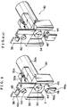
- As shown in Figs. 6 and 7, a manually operated trigger type dispenser 110 provided with a nozzle cover type child proof mechnism has a
nozzle cover 138, anozzle 130 and ahinge 136 connecting thenozzle cover 138 to thenozzle 130. Thenozzle 130, thenozzle cover 138 and thehinge 136 are integrally molded from a plastics material. Anorifice 134 is formed substantially at the center of the front surface of thenozzle 130, and acylindrical portion 140 which closely contacts theorifice 134 and ensures liquid tightness is formed on the rear surface (inner surface) of thenozzle cover 138. Thenozzle cover 138 can be fixed to thenozzle 130 irrespective of whether or not theorifice 134 is covered with thenozzle cover 138. As shown Fig. 7(A), thenozzle cover 138 is rotated in the direction of the arrow and is pushed into a depression 111 formed in the front surface ofnozzle 130. Then, anengaging piece 113 on the rear surface of thenozzle cover 138 is held betweenholding portions cylindrical portion 140 closely contacts the front surface of theorifice 134 to cover theorifice 134 in liquid tightness (see Figs. 6 and 7(B)). As shown in Fig. 7(B), thenozzle cover 138 is rotated in the direction of the arrow and pressed against the upper surface of thenozzle 130. Then, thecylindrical portion 138a on the front surface of thenozzle cover 138 engages anengaging groove 130c in the upper surface of thenozzle 130 so that thenozzle cover 138 is fixed to thenozzle 130. Atrigger 112 has an upper end fitted in the lateral wall of a dispenser body and is connected to the dispenser body so as to rotate around a pivot 122. Thetrigger 112 is pressed against the rear surface of thenozzle 130 by urging force of a return spring so that the initial position of the trigger is set. - Even if the container happens to fall by mistake and the trigger is swung. or a child happens to move the trigger mischievously. liquid is prevented from flowing out and thus an unexpected accident can be avoided when the
orifice 134 is covered with thenozzle cover 138 in liquid tightness. Since thenozzle cover 138 is fixed to the upper surface of thenozzle 130, pressurized liquid from theorifice 134 does not hit against thenozzle cover 138 and is not scattered while the dispenser is being used. - Apparently, the shape of the child proof mechanism including a nozzle cover is a little complicated but its number of parts does not increase. The nozzle cover is held on the front surface of the nozzle when the orifice of the nozzle is covered with the nozzle cover. Thus, the appearance is not spoilt When the orifice of the nozzle is not covered, the nozzle cover can engage the upper surface of the nozzle cover. Therefore. the dispenser gives no strange impression and no poor appearance. Recently, therefore, child proof mechanisms of a nozzle cover type have been generally used.
- With the conventional dispenser provided with a child proof mechanism of a nozzle cover type, the operator holds the lower end portion of the
nozzle cover 138 with the finger and pulls it toward him or her. When the pulling force (the traction force) is larger than the force which holds the nozzle cover (the holding force or locking force), the nozzle cover is released immediately and theorifice 134 of thenozzle 130 is opened. - It is well known that, with the conventional dispenser the child proof is released by pulling the nozzle cover. A child can release the child proof very easily, and thus the dispenser is apt to lose its child proof function.
- It is accordingly an object of the present invention to provide a manually operated trigger type dispenser and a child proof mechanism which cannot be released when the nozzle cover is pulled in the well known manner. The invention is as claimed in claim 1.
- For example , a hook may be formed on the rear surface of the nozzle cover and a cantilever having a hook engageable with the hook of the nozzle cover may be formed on the front surface of the nozzle. When the cantilever is bent downward by pushing, the hooks are disengaged from each other.
- The hook of the cantilever may be engageable with the nozzle cover by means other than a hook formed on the rear surface of the nozzle - for example, the cantilever may be arranged so the cantilever passes underneath the bottom edge of the nozzle cover with the hook engageable with the front surface of the nozzle cover.
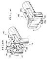
- Fig. 1 is a partially broken side view of a manually operated trigger type dispenser according to one embodiment of the present invention;
- Fig, 2 is an enlarged perspective view of a nozzle incorporated into the dispenser shown in Fig. 1;
- Fig. 3 is an enlarged view of the part A in Fig. 1;
- Figs. 4(A) and 4(B) are enlarged perspective views, each showing a nozzle of further embodiments of the present invention, and the nozzle corresponds to the nozzle of Fig.2;
- Figs. 5(A) and 5(B) are partially broken enlarged views, showing the nozzles of Fig. 4(A) or 4(B),respectively;
- Fig. 6 is a partiallly broken side view of a conventional manually operated trigger type dispenser; and
- Fig. 7 is an enlarged perspective view of the dispenser shown in Fig. 6.
- Embodiments of the present invention will be described in detail with reference to the accompanying drawings.
- As shown in Fig. 1, a manually operated
trigger type dispenser 10 according to the present invention is provided with atrigger 12 pressed by urging force of a return spring 11 so as to be set at an outer initial position. Thetrigger 12 is fitted on the lateral wall of adispenser body 14 so as to rotate or swing. A pivot is shown at 22. Thetrigger 12 is interconnected to apiston 16 so that thepiston 16 is reciprocated in a cylinder in response to the swing of thetrigger 12. Thedispenser body 14 is threadably engaged with themouth 21 of acontainer 20 by means of abottle cap 18. As thepiston 16 is reciprocated in the cylinder, liquid in thecontainer 20 is sucked up into the cylinder through asuction tube 24 and a primary valve, and is compressed. The pressurized liquid flows out of the cylinder through a secondary valve and flows through a flowing-out passage formed in the dispenser body. Anozzle 30 is fitted in the front end of the passage of thedispenser body 14, and a spinner (or a swirling member) 32 is housed in thenozzle 30. The pressuried liquid is swirled by thespinner 32 and is jetted, as a spray, out of an orifice (flowing-out port) 34 formed in the substantially central portion of the front surface of thenozzle 30. - Since the internal structure of the manually operated
trigger type dispenser 10 is identical with the conventional one, the detail thereof is omitted because it does not fall in the scope of the present invention. Such the structure of a conventional dispenser is disclosed in U.S.-A- 4,815,663 (Tada). - For example, the
nozzle 30 has atubular portion 30a disposed at the rear side and fitted in a tubular portion forming the flowing-out passage of thedispenser body 14. Aprojection 30b formed on the upper surface of thenozzle 30 is engaged with an engaging hole correspondingly formed in the upper surface of thedispenser body 14. Thenozzle 30 is irrotationally fixed to thedispenser body 14 by abutting the upper portion of the rear surface and the right and left end portions of thenozzle 30 against the front end of thedispenser body 14. Thenozzle 30 is provided with anozzle cover 38 molded from a plastics material and connected to thenozzle 30 by ahinge 36. When acylindrical portion 40 formed on the rear surface of thenozzle cover 38 closely contacts anorifice 34 formed on the front surface of thenozzle 30 and covers theorifice 34 in liquid tightness, the liquid is prevented from flowing out of theorifice 34. - As seen from Fig. 2 an embodiment of the present invention includes a
hook 42 formed on a portion of the rear surface of thenozzle cover 38 which is adjacent to its lower edge. Acantilever 44 extending forward is formed on the front surface of thenozzle 30 and a downward extendingbent portion 44a is formed on the front end of thecantilever 44.Notches cantilever 44 so as to perform molding easily. An engaging portion such as ahook 46 with which thehook 42 of thenozzle cover 38 is engaged is formed on the upper surface of thecantilever 44. Thehooks - As shown in Fig. 2, when the
nozzle cover 38 is folded forward and is pushed into a space 11 in the front surface of thenozzle 30 by rotating in the counterclockwise direction, the shoulder surfaces 42a and 46a abut against each other and thehook 42 and thecantilever 44 flex or bend to allow thehook 42 to ride over thehook 46 of thecantilever 44. Thereafter, thehook 42 and thecantilever 44 regain their original shape, and thehooks hooks cylindrical portion 40 on the rear surface of thenozzle cover 38 closely contacts theorifice 34 on the front surface of thenozzle 30 and covers the same in liquid tightness, as shown in Fig. 1, whereby the liquid is prevented from flowing out of theorifice 34. By pushing the downward extendingbent portion 44a on the front end of thecantilever 44 for the use of the dispenser, thecantilever 44 is bent or flexed and thehook 46 of thecantilever 44 is removed from the position opposed to thehook 42. - In the construction in which the
nozzle 30 and thenozzle cover 38 connected to thenozzle 30 by thehinge 36 are integrally molded from a plastics material, an inherent elastic force for setting thenozzle cover 38 to a non-restrictive natural state is applied to thenozzle cover 38. When thehook 46 of thecantilever 44 is moved from the position opposed to thehook 42, thenozzle cover 38 is sprung upward by the inherent elastic force to open theorifice 34. In other words, thehook 42 of thenozzle cover 38 and thehook 46 of thecantilever 44 are disengaged from each other automatically by pushing thebent portion 44a. After disengagement, the operator places his finger on the lower end of thenozzle cover 38 and rotates thenozzle cover 38 in the clockwise direction around thehinge 36 in Fig. 1, such that thecylindrical portion 38a of the front surface of thenozzle cover 38 is engaged with the engaginggroove 30c formed in the upper surface of thenozzle 30 to fix thenozzle cover 38. Thus, thenozzle cover 38 does not hinder the pressurized liquid from flowing out of theorifice 34 during the operatiion of thedispenser 10. - In the conventional dispenser of this kind, the liquid tightness of the orifice is released only by pulling the nozzle cover and the liquid can flow out immediately. In the present invention, on the other hand, the
cantilever 44 is pushed instead of being pulled as is in the conventional case. If thecantilever 44 is not pushed, theorifice 34 is not released from the liquid tight state. Thus, even when thecontainer 20 falls by mistake or a child pulls thenozzle cover 38 of thedispenser 10, the liquid does not flow out easily. - In this way, child proof is released not by the well known pulling opeation (traction) of the nozzle cover but by the pushing operation of the
cantilever 44 which is contrary to the conventional pulling operation and is not anticipated by the prior art. Thus, child proofness is ensured - The following advantages of the child proofness attained by the nozzle cover are retained in the present invention:
- (1) the molding is performed without difficulty;
- (2) the number of components does not increase; and
- (3) the nozzle cover can be engaged with the upper surface of the nozzle easily when the orifice of the nozzle is not covered.
- In the embodiment, the downward extending
bent portion 44a is formed on the front end of thecantilever 44. Thus, thecantilever 44 is pushed and bent downward easily. This allows thehooks cantilever 44 is not always limited to the above-mentioned one but may be any other structure. For example, thecantilever 44 may have such a large length that it extends beyond thenotch 43 of thenozzle cover 38 even when thehooks cantilever 44 may have a step portion extending under the lower end of thenozzle cover 38 not to abut against thenozzle cover 38. - The engaging portion of the cantilever which is engaged with the
hook 42 is not limited to thehook 46 but any other structure may be adopted. As shown in Figs. 4(A) and 5(A), for example, thehook 42 may be engaged with an engaginghole 48 formed in thecantilever 44. Further, as shown in Figs. 4(B) and 5(B), an upward extendingbent portion 44b may be formed on the front end of thecantilever 44 and thehook 42 may be engaged with an engaginghole 50 formed in thebent portion 44b. The engaginghole 50 is a through hole in Figs. 4(B) and 5(B), but may be a blind hole. - The front surface of the
trigger 12 may be disposed behind thecantilever 44 at the initial position of thetrigger 12 so that thecantilever 44 is prevented from being bent downward in order not to disengage thehook 42 of thenozzle cover 38 and the engaging portion of thecantilever 44 from each other. As shown by one-dotted chain lines in Figs. 1 and 3, for example, aprojection 12a is formed on the front surface of thetrigger 12 so that thetrigger 12 directly abuts against the lower surface of thecantilever 44 by the urging force of the return spring 11 to set the initial position of thetrigger 12. - Since the
projection 12a on the front surface of thetrigger 12 abuts against the lower suface of thecantilever 44, a space which allows the downward bending of thecantilever 44 does not exist behind thecantilever 44, the engagement and disengagement between thehook 42 of thenozzle cover 38 and thehook 46 of thecantilever 44 are prevented by theprojection 12a of thetrigger 12. When the operator uses thedispenser 10, thetrigger 12 is pulled to move theprojection 12a downward to create a space behind thecantilever 44 so that thecantilever 44 can be bent downward. Then pushing of the downward extendingbent portion 44a of thecantilever 44 bends or flexes thecantilever 44 downward to move thehook 46 of thecantilever 44 outside of the position opposing to thehook 42 of thenozzle cover 38. - The structure of preventing the
cantilever 44 from being pushed by theprojection 12a of thetrigger 12 provides such an advantageous effect in that liquid tightness is maintained unless thecantilever 44 is pushed after the trigger is pulled. With the dispenser which requires two steps to operate, the liquid does not flow out easily when thecontainer 20 falls by mistake or a child touches the dispenser. In other words, even if thecontainer 20 provided with thedispenser 10 falls by mistake, there is few possibility that the traction of thetrigger 12 and the pushing of thecantilever 44 occur accidentally and simultaneously. When a child plays with adispenser 10 according to the present invention, unexpected flow-out of the liquid is fully prevented because he or she cannot pull thetrigger 12 and push thecantilever 44 simultaneously. Two operation steps as described above improve a child proof function or an accident preventing function greatly. Although the easinesss of usage is slightly sacrificed, this inconvenience occurs merely at the time of the engagement and disengagement. However, this causes no problem to the operation of thedispenser 10, and thedispenser 10 can be used in the same way as in the conventional way. - In this embodiment, the
trigger 12 is abutted against the lower surface of thecantilver 44 so as to prevent thecantilever 44 from being bent downward, but the structure of preventing the bending of thecantilever 44 is not limited thereto. The front surface of thetrigger 12 may be abutted against the rear surface of the downward extendingbent portion 44a, as shown in Fig. 5(A), or a depression 12b surrounding the downward extendingbent portion 44a may be formed in the front surface of thetrigger 12, as shown in Fig. 5(B), so as to prevent the bending of thecantilever 44. - In this embodiment, the initial position of the
trigger 12 is set by abutting thetrigger 12 against thecantilever 44, but the present invention may have a structure which provides a little space between thecantilever 44, and thetrigger 12. Such the structure may be attained by abutting thetrigger 12 against the rear surface of thenozzle 30 instead of abutting thetrigger 12 against thecantilever 44 so that a little space is left in order to prevent the bending of thecantilever 44 and the front surface of thetrigger 12 is disposed just behind the lower surface of thecantilever 44 or just behind the downward extendingbent portion 44a. - The above-mentioned embodiments are only examples which explain the present invention and do not limit the scope of the present invention. Needless to say, various modifications and alterations are possible as long as they fall within the scope of the present invention.
Claims (9)
- A manually operated trigger type dispenser (10) provided with a child proof mechanism which prevents a pressurized liquid from flowing out by covering an orifice (34) on a front surface of a nozzle (30) in liquid tightness with a nozzle cover (38) connected to the nozzle (30) by a hinge (36), the nozzle cover (38) and the nozzle (30) being integrally molded from a plastics material, the dispenser (10) being operated so that liquid is sucked into a cylinder and compressed by reciprocation of a piston (16) in cooperation with traction or swing of a trigger (12) and a pressurized liquid flows out of the orifice (34) on the front surface of the nozzle (30). characterized in that the child proof mechanism comprising:
a cantilever (44) formed on the front surface of the nozzle (30) and extending forward;
an engaging portion (46, 48, 50) which is formed on or in the cantilever (44), is engaged with the nozzle cover, for example, with a hook (42) formed on a rear surface of the nozzle cover (38),
when the orifice (34) of the nozzle (30) is covered with the nozzle cover (38) in liquid tightness and is disengaged from the nozzle cover when the cantilever (44) is bent downward. - A manually operated trigger type dispenser (10) according to claim 1, wherein the cantilever (44) is provided with a downward extending bent portion (44a) on a front end thereof.
- A manually operated trigger type dispenser (10) according to claim 1 or 2, wherein the engaging portion of the cantilever (44) is a hook (46) formed on an upper surface of the cantilever (44).
- A manually operated trigger type dispenser (10) according to claim 1 or 2, wherein the engaging portion of the cantilever (44) is an engaging hole (48) formed in an upper surface of the cantilever (44).
- A manually operated trigger type dispenser (10) according to claim 1 or 2, wherein the cantilever (44) is provided with an upward extending bent portion (44b) on a front end thereof, the engaging portion of the cantilever (44) is an engaging hole (50) formed in the upward extending bent portion (44b).
- A manually operated trigger type dispenser (10) according to any one of preceding claims 1 to 5, wherein a front surface of the trigger (12) is disposed behind the cantilever (44) at an initial position of the trigger (12) so as not to produce a space for bending the cantilever (44) between the cantilever (44) and the trigger (12)
- A manually operated trigger type dispenser (10) according to any one of preceding claims 1 to 5, wherein the trigger (12) abuts against a rear surface of the cantilever (44) to set an initial position of the trigger (12).
- A manually operated trigger type dispenser (10) according to claim 2, wherein the trigger (12) abuts against a rear surface of the downward extending bent portion (44a) to set an initial position of the trigger (12).
- A child proof mechanism for a manually operated trigger type dispenser (10) connected to a mouth (21) of a container (20) and sucking liquid from the container (20) into a cylinder, pressurizing the liquid and causing the pressurized liquid to flow out by reciprocation of a piston (16) in cooperation with traction of a trigger (12), characterized in that the mechanism comprising:
a nozzle (38) connected to a nozzle (30) by a hinge (36) and covering an orifice (34) of a front surface of the nozzle (30) in liquid tightness so as to prevent flowing out of the pressurized liquid, the nozzle cover (38) and the nozzle (30) being integrally molded from a plastics material;
a cantilever (44) formed on the front surface of the nozzle (30) and extending forward;
an hook(42) formed on a rear surface of the nozzle cover (38); and
an engaging portion (46, 48, 50) which is formed on or in the cantilever (44), is engaged with the hook (42) when the orifice (34) of the nozzle (30) is coverd with the nozzle cover (38) in liquid tightness and is disengaged from the hook (42) when the cantilever (44) is bent downward.
Applications Claiming Priority (2)
| Application Number | Priority Date | Filing Date | Title |
|---|---|---|---|
| JP213571/93 | 1993-08-06 | ||
| JP5213571A JP2857032B2 (en) | 1993-08-06 | 1993-08-06 | Manual trigger type dispenser and its nozzle |
Publications (2)
| Publication Number | Publication Date |
|---|---|
| EP0641723A1 true EP0641723A1 (en) | 1995-03-08 |
| EP0641723B1 EP0641723B1 (en) | 1999-02-24 |
Family
ID=16641415
Family Applications (1)
| Application Number | Title | Priority Date | Filing Date |
|---|---|---|---|
| EP94305713A Expired - Lifetime EP0641723B1 (en) | 1993-08-06 | 1994-08-02 | A manually operated trigger type dispenser |
Country Status (4)
| Country | Link |
|---|---|
| US (1) | US5564604A (en) |
| EP (1) | EP0641723B1 (en) |
| JP (1) | JP2857032B2 (en) |
| DE (1) | DE69416627T2 (en) |
Cited By (2)
| Publication number | Priority date | Publication date | Assignee | Title |
|---|---|---|---|---|
| EP0744217A1 (en) * | 1994-12-09 | 1996-11-27 | Yoshino Kogyosho Co., Ltd. | Atomizer |
| EP0759327A1 (en) * | 1995-08-18 | 1997-02-26 | Calmar Inc. | Nozzle cover for trigger spray |
Families Citing this family (16)
| Publication number | Priority date | Publication date | Assignee | Title |
|---|---|---|---|---|
| US5649646A (en) * | 1995-06-02 | 1997-07-22 | Contico International, Inc. | Child resistant nozzle |
| US5722569A (en) * | 1996-07-19 | 1998-03-03 | Contico International, Inc. | Trigger sprayer with discharge port blocking mechanism |
| ES2117470T3 (en) * | 1996-10-24 | 1998-08-01 | Calmar Albert Gmbh | CHILD SAFETY HITCH FOR TRIGGER SPRAYER. |
| USD406052S (en) * | 1996-12-20 | 1999-02-23 | Reckitt & Colman Products Limited | Bottle with trigger pump |
| USD406060S (en) * | 1996-12-20 | 1999-02-23 | Reckitt & Colman Products Limited | Trigger pump |
| WO1998058872A1 (en) * | 1997-06-20 | 1998-12-30 | Continental Sprayers International, Inc. | Child-resistant nozzle for manual pump dispenser |
| US6244469B1 (en) | 1998-01-14 | 2001-06-12 | Michael G. Knickerbocker | Child resistant trigger for dispenser |
| JPH11276945A (en) * | 1998-03-31 | 1999-10-12 | Toyo Seikan Kaisha Ltd | Safety device for trigger type dispenser |
| JP3781904B2 (en) * | 1998-05-01 | 2006-06-07 | 株式会社吉野工業所 | Synthetic resin return springs in trigger type liquid ejectors |
| US6286723B1 (en) | 2000-03-06 | 2001-09-11 | Saint-Gobain Calmar Inc. | Self-resetting child-resistant trigger sprayer |
| US6364171B1 (en) * | 2001-02-21 | 2002-04-02 | Owens-Illinois Closure, Inc. | Articulated trigger/cover unit for a pump dispenser |
| US7036689B1 (en) | 2002-04-22 | 2006-05-02 | Continental Afa Dispensing Company | Child-resistant trigger sprayer |
| US7032777B2 (en) * | 2003-10-16 | 2006-04-25 | Saint-Gobain Calmar, Inc. | Child-resistant trigger sprayer |
| US7303150B2 (en) * | 2005-11-22 | 2007-12-04 | Meadwestvaco Corporation | Foam and spray nozzles having a hinged door and a trigger dispenser incorporating same |
| US20070119982A1 (en) * | 2005-11-29 | 2007-05-31 | Hildebrand George R | Foam nozzles having a locked screen door and a trigger dispenser incorporating same |
| JP5124149B2 (en) * | 2007-02-19 | 2013-01-23 | 花王株式会社 | Trigger type liquid ejector |
Citations (2)
| Publication number | Priority date | Publication date | Assignee | Title |
|---|---|---|---|---|
| US4230277A (en) * | 1977-03-02 | 1980-10-28 | Tetsuya Tada | Trigger type sprayer with integrally formed locking nozzle cover |
| US4558821A (en) * | 1983-03-03 | 1985-12-17 | Canyon Corporation | Trigger-type sprayer with integrally formed housing, trigger, nozzle and cylinder |
Family Cites Families (11)
| Publication number | Priority date | Publication date | Assignee | Title |
|---|---|---|---|---|
| JPS5222448B2 (en) * | 1974-02-12 | 1977-06-17 | ||
| US4022352A (en) * | 1976-04-26 | 1977-05-10 | Pehr Harold T | Container cover and safety closure |
| US4153203A (en) * | 1977-03-02 | 1979-05-08 | Tetsuya Tada | Trigger type sprayer |
| US4346821A (en) * | 1978-03-16 | 1982-08-31 | Afa Consolidated Corporation | Child-resistant closures for container mounted spray dispensers |
| US4463905A (en) * | 1978-06-27 | 1984-08-07 | The Dow Chemical Company | Foam-generating pump sprayer |
| US4516695A (en) * | 1981-02-09 | 1985-05-14 | The Afa Corporation | Child-resistant liquid dispenser sprayer or like apparatus |
| FR2528328B1 (en) * | 1982-06-11 | 1985-11-22 | Valve Precision Sarl | SPRAYING DEVICE FOR LIQUIDS |
| ES273524Y (en) * | 1983-07-14 | 1985-04-16 | Monturas Y Fornituras S.A. | LIQUID PROJECTOR GUN |
| US4852770A (en) * | 1987-12-31 | 1989-08-01 | Specialty Packaging Licensing Co. | Child-resistant dispensing closure |
| US4958754A (en) * | 1989-03-01 | 1990-09-25 | Continental Sprayers, Inc. | Dispenser or sprayer with vent system |
| US5373991A (en) * | 1993-04-09 | 1994-12-20 | Contico International, Inc. | Foamer trigger dispenser with sealing device |
-
1993
- 1993-08-06 JP JP5213571A patent/JP2857032B2/en not_active Expired - Lifetime
-
1994
- 1994-07-21 US US08/278,443 patent/US5564604A/en not_active Expired - Fee Related
- 1994-08-02 DE DE69416627T patent/DE69416627T2/en not_active Expired - Fee Related
- 1994-08-02 EP EP94305713A patent/EP0641723B1/en not_active Expired - Lifetime
Patent Citations (2)
| Publication number | Priority date | Publication date | Assignee | Title |
|---|---|---|---|---|
| US4230277A (en) * | 1977-03-02 | 1980-10-28 | Tetsuya Tada | Trigger type sprayer with integrally formed locking nozzle cover |
| US4558821A (en) * | 1983-03-03 | 1985-12-17 | Canyon Corporation | Trigger-type sprayer with integrally formed housing, trigger, nozzle and cylinder |
Cited By (5)
| Publication number | Priority date | Publication date | Assignee | Title |
|---|---|---|---|---|
| EP0744217A1 (en) * | 1994-12-09 | 1996-11-27 | Yoshino Kogyosho Co., Ltd. | Atomizer |
| EP0744217A4 (en) * | 1994-12-09 | 1998-05-06 | Yoshino Kogyosho Co Ltd | Atomizer |
| EP1103308A2 (en) * | 1994-12-09 | 2001-05-30 | YOSHINO KOGYOSHO Co., Ltd. | Sprayer comprising a nozzle cover |
| EP1103308A3 (en) * | 1994-12-09 | 2001-08-29 | YOSHINO KOGYOSHO Co., Ltd. | Sprayer comprising a nozzle cover |
| EP0759327A1 (en) * | 1995-08-18 | 1997-02-26 | Calmar Inc. | Nozzle cover for trigger spray |
Also Published As
| Publication number | Publication date |
|---|---|
| JP2857032B2 (en) | 1999-02-10 |
| US5564604A (en) | 1996-10-15 |
| DE69416627D1 (en) | 1999-04-01 |
| EP0641723B1 (en) | 1999-02-24 |
| JPH0747312A (en) | 1995-02-21 |
| DE69416627T2 (en) | 1999-09-09 |
Similar Documents
| Publication | Publication Date | Title |
|---|---|---|
| EP0641723B1 (en) | A manually operated trigger type dispenser | |
| CA2045372C (en) | Child resistant trigger sprayer | |
| US4346821A (en) | Child-resistant closures for container mounted spray dispensers | |
| KR100740574B1 (en) | Trigger type fluid ejector | |
| US6003738A (en) | Child-resistant rotating lock for manually operated pump dispenser | |
| WO2007103922A2 (en) | Trigger sprayer with child resistant indexing nozzle | |
| US6186366B1 (en) | Fluid dispenser with child-resistant nozzle assembly | |
| JP2001314786A (en) | Automatic resetable trigger spray preventing children's accidental ingestion | |
| US5535952A (en) | Safety mechanism for a manually operated trigger activated dispenser | |
| EP0202380A1 (en) | Manually operated trigger type dispenser | |
| MXPA97004790A (en) | Children's proof insurance for asper trigger | |
| US20060043114A1 (en) | Disposable dispenser | |
| EP1524039B1 (en) | Child-resistant trigger spray | |
| US3913805A (en) | One-piece dispenser cap and childproof actuator | |
| US6244469B1 (en) | Child resistant trigger for dispenser | |
| US5649646A (en) | Child resistant nozzle | |
| CA2264833A1 (en) | Spray cap for aerosol container | |
| US7677416B2 (en) | In-line manually operated liquid dispenser with simplified construction | |
| US5762236A (en) | Trigger mechanism for trigger sprayer | |
| CA2273974A1 (en) | Manually operated pump dispenser having child-resistant nozzle | |
| JPH09225363A (en) | Manual trigger type dispenser and its nozzle | |
| EP0872283B1 (en) | Child-resistant trigger actuated pump sprayer | |
| JPH09141148A (en) | Manual trigger type dispenser and its nozzle | |
| JPH08299865A (en) | Manual trigger type dispenser and its nozzle | |
| WO1998058872A1 (en) | Child-resistant nozzle for manual pump dispenser |
Legal Events
| Date | Code | Title | Description |
|---|---|---|---|
| PUAI | Public reference made under article 153(3) epc to a published international application that has entered the european phase |
Free format text: ORIGINAL CODE: 0009012 |
|
| AK | Designated contracting states |
Kind code of ref document: A1 Designated state(s): DE FR GB IT |
|
| 17P | Request for examination filed |
Effective date: 19950811 |
|
| 17Q | First examination report despatched |
Effective date: 19961029 |
|
| GRAG | Despatch of communication of intention to grant |
Free format text: ORIGINAL CODE: EPIDOS AGRA |
|
| GRAG | Despatch of communication of intention to grant |
Free format text: ORIGINAL CODE: EPIDOS AGRA |
|
| GRAH | Despatch of communication of intention to grant a patent |
Free format text: ORIGINAL CODE: EPIDOS IGRA |
|
| GRAH | Despatch of communication of intention to grant a patent |
Free format text: ORIGINAL CODE: EPIDOS IGRA |
|
| GRAA | (expected) grant |
Free format text: ORIGINAL CODE: 0009210 |
|
| AK | Designated contracting states |
Kind code of ref document: B1 Designated state(s): DE FR GB IT |
|
| ITF | It: translation for a ep patent filed |
Owner name: BARZANO' E ZANARDO MILANO S.P.A. |
|
| REF | Corresponds to: |
Ref document number: 69416627 Country of ref document: DE Date of ref document: 19990401 |
|
| ET | Fr: translation filed | ||
| PGFP | Annual fee paid to national office [announced via postgrant information from national office to epo] |
Ref country code: FR Payment date: 19990713 Year of fee payment: 6 |
|
| PGFP | Annual fee paid to national office [announced via postgrant information from national office to epo] |
Ref country code: GB Payment date: 19990729 Year of fee payment: 6 |
|
| RAP2 | Party data changed (patent owner data changed or rights of a patent transferred) |
Owner name: TADA, TETSUYA |
|
| RIN2 | Information on inventor provided after grant (corrected) |
Free format text: TADA, TETSUYA |
|
| PGFP | Annual fee paid to national office [announced via postgrant information from national office to epo] |
Ref country code: DE Payment date: 19991016 Year of fee payment: 6 |
|
| PLBE | No opposition filed within time limit |
Free format text: ORIGINAL CODE: 0009261 |
|
| STAA | Information on the status of an ep patent application or granted ep patent |
Free format text: STATUS: NO OPPOSITION FILED WITHIN TIME LIMIT |
|
| 26N | No opposition filed | ||
| PG25 | Lapsed in a contracting state [announced via postgrant information from national office to epo] |
Ref country code: GB Free format text: LAPSE BECAUSE OF NON-PAYMENT OF DUE FEES Effective date: 20000802 |
|
| GBPC | Gb: european patent ceased through non-payment of renewal fee |
Effective date: 20000802 |
|
| PG25 | Lapsed in a contracting state [announced via postgrant information from national office to epo] |
Ref country code: FR Free format text: LAPSE BECAUSE OF NON-PAYMENT OF DUE FEES Effective date: 20010430 |
|
| PG25 | Lapsed in a contracting state [announced via postgrant information from national office to epo] |
Ref country code: DE Free format text: LAPSE BECAUSE OF NON-PAYMENT OF DUE FEES Effective date: 20010501 |
|
| REG | Reference to a national code |
Ref country code: FR Ref legal event code: ST |
|
| PG25 | Lapsed in a contracting state [announced via postgrant information from national office to epo] |
Ref country code: IT Free format text: LAPSE BECAUSE OF NON-PAYMENT OF DUE FEES Effective date: 20050802 |