EP0645657A1 - Connecting device for optical fibres - Google Patents
Connecting device for optical fibres Download PDFInfo
- Publication number
- EP0645657A1 EP0645657A1 EP94402110A EP94402110A EP0645657A1 EP 0645657 A1 EP0645657 A1 EP 0645657A1 EP 94402110 A EP94402110 A EP 94402110A EP 94402110 A EP94402110 A EP 94402110A EP 0645657 A1 EP0645657 A1 EP 0645657A1
- Authority
- EP
- European Patent Office
- Prior art keywords
- optical fibers
- chassis
- cassettes
- along
- cassette
- Prior art date
- Legal status (The legal status is an assumption and is not a legal conclusion. Google has not performed a legal analysis and makes no representation as to the accuracy of the status listed.)
- Granted
Links
Images


Classifications
-
- G—PHYSICS
- G02—OPTICS
- G02B—OPTICAL ELEMENTS, SYSTEMS OR APPARATUS
- G02B6/00—Light guides; Structural details of arrangements comprising light guides and other optical elements, e.g. couplings
- G02B6/44—Mechanical structures for providing tensile strength and external protection for fibres, e.g. optical transmission cables
- G02B6/4439—Auxiliary devices
- G02B6/444—Systems or boxes with surplus lengths
- G02B6/4453—Cassettes
- G02B6/4455—Cassettes characterised by the way of extraction or insertion of the cassette in the distribution frame, e.g. pivoting, sliding, rotating or gliding
-
- G—PHYSICS
- G02—OPTICS
- G02B—OPTICAL ELEMENTS, SYSTEMS OR APPARATUS
- G02B6/00—Light guides; Structural details of arrangements comprising light guides and other optical elements, e.g. couplings
- G02B6/44—Mechanical structures for providing tensile strength and external protection for fibres, e.g. optical transmission cables
- G02B6/4439—Auxiliary devices
- G02B6/444—Systems or boxes with surplus lengths
- G02B6/4452—Distribution frames
- G02B6/44526—Panels or rackmounts covering a whole width of the frame or rack
Abstract
Description
La présente invention concerne un dispositif de raccordement pour fibres optiques, parfois appelé organiseur d'épissures ou tête de câble.The present invention relates to a connection device for optical fibers, sometimes called a splice organizer or cable head.
On connaît par la demande de brevet français FR-2 646 928 un dispositif de raccordement comprenant un châssis de forme allongée parallélépipédique, muni d'une pluralité de cassettes articulées comportant chacune des moyens pour loger des longueurs de réserve de fibres optiques et les épissures des fibres optiques raccordées. L'amenée des fibres optiques dans le châssis et le départ des fibres optiques vers l'extérieur s'effectue au travers de parois opposées du châssis et le pivotement des cassettes s'effectue autour d'axes parallèles à ces parois opposées. Les fibres optiques entrent et sortent d'une cassette par des passages ménagés sur une paroi de celle-ci parallèle à l'axe de pivotement, ce qui oblige, pour respecter le rayon de courbure minimum des fibres optiques permettant une transmission correcte de la lumière, à éloigner les cassettes de leur axe de pivotement en les montant à l'extrémité de bras articulés. Le pivotement des cassettes s'effectue ainsi dans un volume important, au détriment de la capacité de stockage de fibres optiques, et sur le côté par rapport à l'opérateur chargé du câblage, ce qui rend malaisé les opérations à effectuer dans les cassettes. Un tube est prévu pour guider les fibres optiques depuis le départ des cassettes, et l'insertion des fibres optiques dans ce tube est une opération coûteuse en temps de main-d'oeuvre.French patent application FR-2 646 928 discloses a connection device comprising a chassis of elongated parallelepiped shape, provided with a plurality of articulated cassettes each comprising means for accommodating reserve lengths of optical fibers and the splices of the optical fibers connected. The bringing of the optical fibers into the chassis and the departure of the optical fibers towards the outside takes place through opposite walls of the frame and the pivoting of the cassettes takes place around axes parallel to these opposite walls. The optical fibers enter and leave a cassette through passages formed on a wall thereof parallel to the pivot axis, which requires, in order to respect the minimum radius of curvature of the optical fibers allowing correct transmission of light , move the cassettes away from their pivot axis by mounting them at the end of articulated arms. The pivoting of the cassettes is thus carried out in a large volume, to the detriment of the storage capacity of optical fibers, and on the side relative to the operator in charge of the wiring, which makes the operations to be carried out in the cassettes difficult. A tube is provided for guiding the optical fibers from the departure of the cassettes, and the insertion of the optical fibers into this tube is a costly operation in terms of labor time.
La présente invention vise à remédier à ces inconvénients, et propose un dispositif de raccordement perfectionné, destiné à faciliter notamment les opérations de câblage et d'épissurage des fibres optiques, tout en offrant une grande capacité de stockage de fibres optiques, ce dispositif de raccordement étant du type comprenant un châssis présentant deux parois latérales réunies inférieurement par un fond et comportant une pluralité de cassettes articulées et superposées, munies chacune d'elles de moyens pour loger des longueurs de réserve de fibres optiques et les épissures des fibres optiques raccordées.The present invention aims to remedy these drawbacks, and proposes an improved connection device, intended in particular to facilitate the operations of wiring and splicing of optical fibers, while offering a large storage capacity for optical fibers, this connection device being of the type comprising a chassis having two side walls joined together at the bottom by a bottom and comprising a plurality of hinged and superimposed cassettes, each provided with means for accommodating reserve lengths of optical fibers and the splices of the connected optical fibers.
Selon une première caractéristique de l'invention, le dispositif comporte :
- une paroi avant pour le montage de connecteurs de raccordement des fibres optiques à des modules opto-électroniques,
- un plateau de support horizontal, monté avec une possibilité de coulissement vers l'avant au-dessus de la paroi avant, entre les deux parois latérales du châssis, et ménageant avec le fond de ce dernier un espace protégé d'épanouissement des fibres optiques, ladite pluralité de cassettes étant portée par ledit plateau de support, la cassette inférieure de ladite pluralité étant fixée sur le plateau de support et les autres cassettes de ladite pluralité étant aptes à basculer vers l'arrière pour libérer l'accès à une cassette située dessous, et
- des moyens de guidage des fibres optiques dans ledit espace protégé, agencés pour guider les fibres optiques, en respectant leur rayon de courbure minimum, entre une ouverture du châssis, lesdits connecteurs de raccordement et des entrées et sorties latérales des fibres optiques des cassettes.
- a front wall for mounting connectors for connecting optical fibers to opto-electronic modules,
- a horizontal support plate, mounted with a possibility of sliding forward above the front wall, between the two side walls of the chassis, and providing with the bottom of the latter a protected space for the development of optical fibers, said plurality of cassettes being carried by said support plate, the lower cassette of said plurality being fixed on the support plate and the other cassettes of said plurality being able to tilt backwards to free access to a cassette situated below , and
- means for guiding the optical fibers in said protected space, arranged to guide the optical fibers, respecting their minimum radius of curvature, between an opening of the chassis, said connection connectors and the lateral inputs and outputs of the optical fibers of the cassettes.
De préférence, chaque cassette comporte une entrée et une sortie latérales de fibres optiques, situées à l'opposé l'une de l'autre, deux tambours sur lesquels sont lovées les fibres optiques arrivant et partant respectivement par ladite entrée et ladite sortie latérales et un boîtier destiné à ranger les épissures, situé entre les deux tambours.Preferably, each cassette has a side inlet and a side outlet for optical fibers, located opposite each other, two drums on which are coiled the optical fibers arriving and leaving respectively by said side inlet and outlet and a box for storing splices, located between the two drums.
De préférence, les cassettes sont munies à l'arrière de pattes de montage formées par pliage à angle droit d'un bord arrière relevé de la cassette ou venues de moulage, traversées chacune par deux perçages pour la liaison articulée avec une cassette immédiatement supérieure et une cassette immédiatement inférieure respectivement, lesdites entrées et sorties latérales de fibres optiques étant formées à proximité desdites pattes de montage.Preferably, the cassettes are provided at the rear with mounting tabs formed by bending at right angles to a rear edge raised from the cassette or coming from molding, each crossed by two holes for the articulated connection with an immediately superior cassette and an immediately lower cassette respectively, said lateral optical fiber inlets and outlets being formed near said mounting tabs.
De préférence, les cassettes sont articulées de sorte que le pivotement vers l'arrière s'effectue sur plus de 90°.Preferably, the cassettes are articulated so that the pivoting towards the rear takes place over more than 90 °.
De préférence, les cassettes situées sous la cassette supérieure sont munies chacune de premiers moyens d'accrochage et les cassettes situées au-dessus de la cassette inférieure sont munies chacune de seconds moyens d'accrochage aptes à coopérer avec les premiers moyens d'accrochage, de façon amovible, pour solidariser les cassettes entre elles, les premiers et seconds moyens d'accrochage étant du type mettant en oeuvre un tissu à boucles et un tissu à crochets.Preferably, the cassettes located under the upper cassette are each provided with first attachment means and the cassettes located above the lower cassette are each provided with second attachment means capable of cooperating with the first attachment means, removably, to secure the cassettes to each other, the first and second attachment means being of the type using a fabric with loops and a fabric with hooks.
Avantageusement, ladite ouverture du châssis est ménagée sur un côté du châssis au-dessous du plateau de support, et le dispositif comporte une pièce de guidage apte à conférer aux fibres optiques, à l'extérieur du châssis, un rayon de courbure suffisant lors de leur passage par ladite ouverture, munie de moyens de montage réversibles sur le châssis de sorte que la pièce de guidage peut être orientée vers le bas ou vers le haut selon la direction à donner aux fibres optiques à l'extérieur du châssis.Advantageously, said opening of the chassis is formed on one side of the chassis below the support plate, and the device comprises a guide part capable of imparting to the optical fibers, outside the chassis, a sufficient radius of curvature during their passage through said opening, provided with reversible mounting means on the chassis so that the guide piece can be oriented downwards or upwards according to the direction to be given to the optical fibers at the outside of the chassis.
De préférence, des étriers de guidage des fibres optiques sont disposés sur le fond du châssis, sur une paroi arrière du châssis et sur ses parois latérales, pour guider les fibres optiques depuis ladite ouverture du châssis selon une ligne infléchie dont la concavité, puis la convexité est orientée vers une première paroi latérale du châssis du côté de laquelle est ménagée ladite ouverture, selon une ligne décrivant un U dont la concavité est orientée vers ladite première paroi latérale, selon une ligne rectiligne longeant la paroi arrière du châssis en allant vers le haut et selon une ligne décrivant un U dont la convexité est orientée vers ladite première paroi latérale jusqu'aux entrées latérales des cassettes, et depuis les sorties latérales des cassettes, selon une ligne décrivant un U dont la concavité est orientée vers ladite première paroi latérale, selon une ligne rectiligne longeant la paroi arrière du châssis en descendant et selon une ligne faisant un virage à 90° vers la paroi avant.Preferably, stirrups for guiding the optical fibers are arranged on the bottom of the chassis, on a rear wall of the chassis and on its side walls, to guide the optical fibers from said opening of the chassis along an inflected line whose concavity, then the convexity is oriented towards a first side wall of the chassis on the side of which said opening is formed, along a line describing a U whose concavity is oriented towards said first side wall, along a straight line running along the rear wall of the chassis going towards the top and along a line describing a U whose convexity is oriented towards said first side wall up to the lateral inlets of the cassettes, and from the lateral outlets of the cassettes, along a line describing a U whose concavity is oriented towards said first side wall , along a straight line running along the rear wall of the chassis down and along a line making a 90 ° turn towards the front wall.
De préférence, le châssis est installé entre deux montants verticaux d'un bâti au moyen de pièces de fixation comportant chacune une semelle à rapporter sur la face interne d'une paroi latérale du châssis et des crochets à engager dans des perçages de la paroi latérale et du montant adjacent.Preferably, the chassis is installed between two vertical uprights of a frame by means of fastening pieces each comprising a sole to be attached to the internal face of a side wall of the chassis and hooks to be engaged in holes in the side wall. and the adjacent upright.
D'autres caractéristiques et avantages de la présente invention apparaîtront à la lecture de la description détaillée qui va suivre, d'un exemple de réalisation non limitatif de l'invention et à l'examen du dessin annexé sur lequel :
- la figure 1 est une vue en perspective d'un dispositif de raccordement conforme à l'invention, installé entre deux montants d'un bâti, le plateau de support des cassettes étant représenté en position sortie,
- la figure 2 est une vue analogue à la figure 1, montrant le dispositif de raccordement avec les cassettes basculées vers l'arrière pour libérer l'accès à la cassette inférieure,
- la figure 3 est une vue en perspective montrant le dispositif de raccordement avec le plateau de support des cassettes représenté en position rétractée,
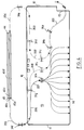
- la figure 4 est une vue de dessus indiquant schématiquement le trajet des fibres optiques à l'intérieur du châssis,
- la figure 5 est une vue en perspective, partielle, montrant la paroi avant équipée de différents types de connecteurs,
- la figure 6 est une vue de face d'un exemple de réalisation d'une découpe de la paroi avant,
- la figure 7 est une vue de dessus d'une pièce de fixation utilisée pour installer le châssis entre les montants du bâti,
- la figure 8 est une vue de côté selon la flèche VIII de la figure 7, et
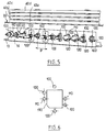
- la figure 9 est une vue en perspective, partielle, d'une cassette.
- FIG. 1 is a perspective view of a connection device according to the invention, installed between two uprights of a frame, the cassette support plate being shown in the extended position,
- FIG. 2 is a view similar to FIG. 1, showing the connection device with the cassettes tilted backwards to free access to the lower cassette,
- FIG. 3 is a perspective view showing the device for connection with the cassette support plate shown in the retracted position,
- FIG. 4 is a top view schematically indicating the path of the optical fibers inside the chassis,
- FIG. 5 is a partial perspective view showing the front wall fitted with different types of connectors,
- FIG. 6 is a front view of an exemplary embodiment of a cutout of the front wall,
- FIG. 7 is a top view of a fixing piece used to install the chassis between the uprights of the frame,
- FIG. 8 is a side view along arrow VIII of FIG. 7, and
- Figure 9 is a partial perspective view of a cassette.
Dans toute la description qui suit, les mots ou groupes de mots "avant, arrière" et "hauteur" se réfèreront respectivement aux axes X et Z du repère orthogonal (XYZ) représenté sur la figure 1.Throughout the following description, the words or groups of words "front, rear" and "height" will refer respectively to the axes X and Z of the orthogonal coordinate system (XYZ) represented in FIG. 1.
Le dispositif de raccordement conforme à l'invention représenté sur les figures 1 à 9 comprend un châssis 10 allongé dans la direction de l'axe Y, à installer entre deux montants verticaux 1 et 2, s'étendant selon l'axe Z, d'un bâti connu en lui-même. Les montants verticaux 1 et 2 présentent deux parois 1a et 2a planes et parallèles au plan XZ, sur chacune desquelles sont ménagés des perçages 3, 4 juxtaposés horizontalement et régulièrement espacés verticalement, pour le montage du châssis 10 à une hauteur souhaitée. Ces perçages 3, 4 présentent une section carrée et le bord inférieur de deux perçages 3, 4 juxtaposés horizontalement se situe dans un même plan horizontal parallèle au plan XY.The connection device according to the invention shown in Figures 1 to 9 comprises a
Le châssis 10 présente deux parois latérales 11 et 12, planes et parallèles, fixées sur les parois 1a et 2a des montants 1 et 2 respectivement. Avantageusement, le montage du châssis 10 sur les parois 1a et 2a s'effectue au moyen de deux pièces de fixation 300, dont on a représenté un exemplaire sur les figures 7 et 8. Chaque pièce de fixation 300 est symétrique par rapport à un plan médian de symétrie P, comprend une semelle plane allongée 305 et deux crochets 301 et 302 venus de formation avec celle-ci et formant saillie sur l'une de ses faces principales. Les crochets 301 et 302 sont formés par découpage puis pliage en équerre de deux languettes situées chacune au voisinage d'une extrémité longitudinale 308, 309 de la semelle 305.The
On a référencé 306 la paroi de raccordement des languettes sur la semelle 305, et 307 la paroi d'extrémité des languettes, parallèle au plan de la semelle 305, formant un coude à angle droit avec la paroi de raccordement 306 en direction de l'extrémité longitudinale 308. La semelle 305 est taraudée en 305a entre l'extrémité longitudinale 309 et le crochet 301. Les semelles 305 des pièces de fixation 300 sont respectivement rapportées sur les faces en regard des parois latérales 11 et 12 et les crochets 301 et 302 sont introduits, à la faveur de perçages de ces parois latérales, dans des perçages 3 et 4 des montants 1 et 2, puis les semelles sont déplacées horizontalement jusqu'à ce que les parois de raccordement 306 butent contre les bords verticaux des perçages 3 et 4. La distance entre les faces en regard de la semelle 305 et des parois d'extrémité 307 est légèrement supérieure à l'épaisseur totale d'une paroi 1a ou 2a d'un montant du bâti et d'une paroi latérale 11 ou 12 du châssis 10. Deux vis d'immobilisation des pièces de fixation 300 sont ensuite respectivement introduites dans les taraudages 305a.The connection wall of the tongues is referenced 306 on the sole 305, and 307 the end wall of the tongues, parallel to the plane of the sole 305, forming a bend at right angles to the
Les parois latérales 11 et 12 sont réunies, sur leur bord vertical arrière, par une paroi arrière 16 s'étendant verticalement perpendiculairement au plan des parois latérales 11 et 12, et sur leur bord inférieur horizontal, par un fond horizontal 13 s'étendant perpendiculairement au plan des parois latérales 11 et 12 et au plan de la paroi arrière 16. Le châssis 10 présente une paroi avant 14 s'étendant perpendiculairement au plan du fond 13, venue de pliage avec celui-ci, pour le montage sur le châssis 10 d'une pluralité de connecteurs de raccordement, comme cela sera précisé dans la suite. La paroi avant 14 s'étend sur une hauteur inférieure à celle des parois latérales 11 et 12 et, dans l'exemple de réalisation décrit, sur le quart environ de la hauteur de ces dernières. Le bord vertical avant de la paroi latérale 12 se situe en retrait, selon l'axe X, du bord vertical avant de la paroi latérale 11. Le bord horizontal avant du fond 13 se situe dans un même plan vertical, perpendiculaire à l'axe X, que le bord vertical avant de la paroi latérale 11.The
Un plateau de support 20 est monté avec une possibilité de coulissement vers l'avant selon l'axe X au-dessus de la paroi avant 14, entre les deux parois latérales 11 et 12 du châssis 10. Plus particulièrement, le plateau de support 20 comporte une plaque de base 21 plane et horizontale, de forme rectangulaire allongée selon l'axe Y, délimitée selon l'axe X par des bords avant 22a et arrière 22b parallèles, et la plaque de base 21 est munie à ses extrémités longitudinales, de bords latéraux relevés 23 et 24 s'étendant verticalement et depuis le bord avant horizontal 22a de la plaque de base 21 vers l'arrière, au-delà du bord arrière horizontal 22b et sur une longueur correspondant sensiblement à la profondeur du châssis 10 mesurée selon l'axe X entre le plan de la paroi avant 14 et le plan de la paroi arrière 16. Les bords latéraux relevés 23 et 24 sont respectivement fixés par leur face externe sur deux rails 25 et 26 montés à coulissement dans des glissières horizontales 27 et 28 rapportées sur les faces en regard des parois latérales 11 et 12. Le plateau de support 20 peut coulisser selon l'axe X entre une position escamotée, représentée sur la figure 3 et une position sortie représentée sur les figures 1 et 2.A
Sur la face supérieure de la plaque de base 21 est montée une pluralité de cassettes 40a, 40b, 40c et 40d articulées entre elles et superposées, comprenant chacune des moyens pour loger des longueurs de réserve de fibres optiques et les épissures des fibres optiques raccordées. Chaque cassette comporte un cadre de cassette de forme générale rectangulaire allongée selon l'axe Y, constitué d'une paroi de fond plane délimitée selon l'axe X par deux bords relevés longitudinaux 47a parallèles et opposés et selon l'axe Y par deux bords latéraux 47b parallèles et opposés, de même hauteur que les bords longitudinaux 47a, venus de pliage ou de moulage avec la paroi de fond. Plus particulièrement, la cassette inférieure référencée 40a repose en porte-à-faux par sa face inférieure sur la plaque de base 21, avec son bord relevé longitudinal avant 47a situé légèrement en retrait du bord longitudinal avant 22a de la plaque de base 21. La longueur selon l'axe X des bords latéraux 47b correspond à peu près au double de la largeur de la plaque de base 21.On the upper face of the
Chaque cassette est articulée autour d'un axe de pivotement parallèle à l'axe Y au moyen de deux pattes de montage latérales 46 venues de pliage ou de moulage avec le cadre de la cassette. On a représenté, à titre d'illustration, sur la figure 9 le coin arrière droit de la cassette 40b. On aperçoit sur cette figure une patte de montage 46 formée par pliage, autour d'une ligne de pliage perpendiculaire au plan de la paroi de fond du cadre de la cassette, d'une languette initialement située dans le prolongement du bord longitudinal arrière 47a et présentant une partie s'étendant vers le bas sous la paroi de fond du cadre de la cassette, sur une hauteur correspondant sensiblement à la hauteur des bords relevés 47a et 47b. La patte de montage 46 est munie de deux perçages 48a et 48b situés respectivement au-dessous et au-dessus du plan de la paroi de fond du cadre de la cassette. Ces perçages 48a et 48b sont aptes à accueillir chacun un axe d'articulation du cadre respectivement sur la cassette immédiatement inférieure et sur la cassette immédiatement supérieure. Des languettes de retenue 47c sont formées par pliage à angle droit vers l'intérieur d'extensions prolongeant vers le haut les bords relevés 47a et 47b et sont destinées à maintenir les fibres optiques enroulées sur des tambours 41 et 42 rapportés sur la paroi de fond de chaque cassette, comme cela sera précisé par la suite.Each cassette is articulated around a pivot axis parallel to the Y axis by means of two lateral mounting lugs 46 which come from folding or molding with the frame of the cassette. FIG. 9 shows the rear right corner of the
Une ouverture 15 est ménagée en avant de la paroi latérale 12 pour l'amenée et le départ des fibres optiques entre l'extérieur et l'intérieur du châssis 10. Cette ouverture 15 débouche dans un espace protégé 30 d'épanouissement des fibres optiques, délimité inférieurement par le fond 13 du châssis 10, à l'arrière par la paroi arrière 16, sur les côtés par les parois latérales 11 et 12, à l'avant par la paroi avant 14 et supérieurement, lorsque le plateau de support 20 est en position escamotée comme représenté sur la figure 3, par la plaque de base 21 munie de la cassette inférieure 40a. Lorsque le plateau de support 20 est en position escamotée comme représenté sur les figures 1 et 2, l'espace protégé 30 est entièrement accessible par le dessus. L'ouverture 15 est située entre les deux branches d'un étrier fixé par sa base sur le fond 13 du châssis.An
Ces branches présentent des faces opposées crantées pour le montage, amovible, sur celles-ci d'une pièce de guidage 50 destinée à conférer aux fibres optiques un rayon de courbure suffisamment grand pour une transmission correcte de la lumière entre l'ouverture 15 et un câble C d'amenée ou de départ des fibres optiques. La pièce de guidage 50 est constituée par une plaque cintrée à 90°, munie à une extrémité de deux perçages à introduire dans les branches de l'étrier, ces dernières étant aptes à se déformer élastiquement en rapprochement l'une de l'autre lors de l'insertion de la plaque sur l'étrier. La pièce de guidage 50 est montée sur l'étrier avec la convexité de sa plaque cintrée orientée vers le haut ou vers le bas selon la direction à conférer aux fibres optiques à l'extérieur du châssis 10.These branches have opposite notched faces for mounting, removable, on these a
Des moyens de guidage des fibres optiques, qui seront précisés dans la suite, sont prévus dans l'espace protégé 30 d'épanouissement des fibres optiques pour guider celles-ci en respectant un rayon de courbure minimum, depuis l'ouverture 15 jusqu'à des entrées et sorties latérales des fibres optiques dans les cassettes, respectivement référencées 44 et 45, situées dans le plan des bords latéraux relevés 47b des cassettes. Les entrées 44 et sorties 45 latérales se situent à proximité de l'axe de pivotement de chaque cassette, défini par l'axe des perçages 48a des pattes de montage 46, entre l'arète arrière verticale 47d d'un bord latéral relevé 47b et le bord relevé arrière 47a, de sorte que les fibres optiques se déplacent peu lorsque les cassettes sont basculées.Means for guiding the optical fibers, which will be specified hereinafter, are provided in the protected
On a représenté sur la figure 2 le dispositif de raccordement avec les trois cassettes 40b, 40c, 40d en position relevée vers l'arrière pour libérer l'accès à la cassette inférieure 40a. Chaque cassette comprend des moyens pour loger des longueurs de réserve de fibres optiques, destinées à des opérations ultérieures d'épissurage ou de raccordement, et des moyens pour ranger les épissures des fibres raccordées.FIG. 2 shows the connection device with the three
Plus particulièrement, comme représenté, chaque cassette comprend deux tambours 41 et 42 sur lesquels sont lovées les fibres optiques arrivant et sortant respectivement par les entrées 44 et sorties 45 latérales et un boîtier 43 situé entre les deux tambours 41 et 42, présentant une pluralité d'encoches juxtaposées, orientées parallèlement à l'axe Y, pour ranger les épissures des fibres optiques raccordées. Les tambours 41 et 42 présentent un diamètre légèrement inférieur à la largeur des cassettes et se situent respectivement sur ces dernières à proximité des bords relevés latéraux 47b. Les languettes de retenue 47c précitées s'étendent deux à deux au-dessus des fibres optiques enroulées sur les tambours 41 et 42, entre ces derniers et les bords longitudinaux 47a et latéraux 47b pour maintenir les fibres optiques en place lorsque les cassettes sont basculées. Le diamètre des tambours 41 et 42 permet de respecter le rayon de courbure imposé au lovage des fibres optiques.More particularly, as shown, each cassette comprises two
Le câble C d'amenée des fibres optiques est fixé, de façon connue en soi, au moyen d'un ou plusieurs colliers, au montant 2 du bâti, au-dessus du plan horizontal contenant les bords horizontaux supérieurs des parois 11, 12 et 16. Les fibres optiques s'étendent nues hors du câble C depuis son point de fixation sur le montant 2 vers le bas et pénètrent dans l'espace protégé 30 d'épanouissement des fibres à l'intérieur du châssis par l'ouverture 15, comme représenté sur la figure 2. Les fibres optiques sont guidées dans cet espace protégé 30 par des étriers de guidage 31a, ..., 31i en matière plastique, comprenant chacun une embase à coller sur une paroi du châssis et deux branches se raccordant chacune à une extrémité perpendiculairement sur cette embase. Les deux branches définissent à leur extrémité libre deux rampes convergeant en direction de l'embase, aptes à se déformer élastiquement en écartement l'une de l'autre pour permettre l'insertion des fibres optiques entre les branches et leur rétention sur l'étrier de guidage.The cable C for supplying the optical fibers is fixed, in a manner known per se, by means of one or more collars, to the
En se référant plus particulièrement à la figure 4, on remarque que le fond 13 du châssis 10 comporte une première série de quatre étriers de guidage disposés pour guider les fibres optiques depuis l'ouverture 15 vers l'entrée latérale 44 des cassettes, située du côté de l'ouverture 15. Les fibres optiques s'étendent à partir de l'ouverture 15 selon une ligne infléchie 201, concave puis convexe vers la droite sur le dessin, c'est-à-dire vers la paroi latérale 12, jusqu'à un premier étrier 31a.Referring more particularly to FIG. 4, it will be noted that the bottom 13 of the
Un deuxième 31b et troisième 31c étriers de guidage sont disposés sur la paroi de fond 13 pour guider les fibres optiques depuis le premier étrier de guidage 31a jusqu'à un quatrième étrier de guidage 31d disposé sur la paroi arrière 16, selon une ligne 202 décrivant un U dont la concavité est tournée vers la paroi latérale 12. Le troisième étrier 31c est positionné dans le fond de la ligne 202. Un cinquième étrier de guidage 31e est fixé sur la paroi latérale 12 pour guider les fibres optiques depuis le quatrième étrier de guidage 31d vers l'entrée latérale 44 des cassettes selon une ligne montante 203 longeant la paroi arrière 16 puis selon une ligne 204 décrivant un U dont la concavité est orientée vers la paroi latérale 11.A second 31b and third 31c guide stirrups are arranged on the
Une deuxième série d'étriers de guidage est disposée pour guider les fibres optiques depuis la sortie latérale 45 des cassettes vers la paroi avant 14 ou vers l'ouverture 15, selon que l'on destine ces fibres optiques à être raccordées à des connecteurs disposés sur la paroi avant 14 ou à être dirigées vers l'extérieur du châssis 10. Un sixième étrier de guidage 31f est disposé sur la paroi latérale 11 pour guider les fibres optiques depuis la sortie latérale 45 des cassettes vers l'espace protégé 30 d'épanouissement des fibres optiques selon une ligne 205 décrivant un U dont la concavité est tournée vers la paroi latérale 12 du châssis 10. Un septième étrier de guidage 31g est disposé sur la paroi arrière 16 pour guider les fibres optiques depuis le sixième étrier de guidage 31f le long d'une ligne 206 rectiligne s'étendant vers le bas. Les fibres optiques à diriger vers la paroi avant 14 sont guidées, depuis le septième étrier de guidage 31g, par un huitième étrier de guidage 31h selon une ligne 207 décrivant un virage à 90° vers la paroi avant 14 et les fibres optiques à diriger vers l'ouverture 15 sont guidées par un neuvième étrier de guidage 31i vers le deuxième étrier de guidage 31b précité, selon une ligne infléchie 208 concave puis convexe vers la paroi latérale 11, et dont le point d'inflexion se situe au niveau du neuvième étrier de guidage 31i. Les fibres optiques rejoignent ensuite l'ouverture 15 selon la ligne infléchie 201.A second series of guide stirrups is arranged to guide the optical fibers from the
Le pivotement vers l'arrière des cassettes s'effectue sur un angle supérieur à 90° de sorte que ces dernières sont retenues en position d'ouverture de façon stable sous l'effet de leur propre poids.The rearward pivoting of the cassettes takes place at an angle greater than 90 ° so that the latter are held in the open position stably under the effect of their own weight.
Des moyens sont prévus pour solidariser, de façon amovible, les cassettes. Cette solidarisation s'effectue de préférence, comme représenté, au moyen de bandes de tissu à boucles 49a, collées sur la face supérieure des tambours 41 et 42 des cassettes 40a, 40b, 40c et au moyen de bandes de tissu à crochets 49b, collées sur la face inférieure de la paroi de fond des cadres des cassettes 40b, 40c et 40d, aptes à venir s'accrocher sur les bandes de tissu 49a de la cassette immédiatement inférieure.Means are provided for removably securing the cassettes. This joining is preferably carried out, as shown, by means of strips of fabric with
La paroi avant 14 est munie, comme représenté sur les figures 5 et 6, d'une pluralité de découpes identiques 130 régulièrement espacées destinées au montage de connecteurs sur cette paroi. La forme de la découpe 130 est choisie de façon à permettre le montage sur la paroi avant 14 de plusieurs types de connecteurs différents. De préférence, chaque découpe 130 est rectangulaire avec un coin tronqué et elle est bordée, verticalement par deux perçages 100 situés de part et d'autre de la découpe, et latéralement par deux couples de perçages 110 et 120 symétriques par rapport à l'intersection des médiatrices reliant les côtés opposés de la découpe 130.The
On a représenté sur la figure 3 le dispositif de raccordement équipé sur sa paroi avant 14 de deux connecteurs reliés respectivement, par des câbles C1 et C2, à une source laser et un dispositif de conversion opto-électronique.FIG. 3 shows the connection device equipped on its
Finalement, le dispositif de raccordement selon l'invention offre une grande capacité de stockage des fibres optiques sous un faible encombrement, permet d'assurer un logement stable et protégé des fibres optiques et une grande fiabilité du raccordement. Le pivotement des cassettes s'effectue de face par rapport à l'opérateur de sorte que la manipulation des fibres optiques et des épissures est aisée. Les fibres optiques s'étendent nues entre le câble d'amenée ou de départ C et les cassettes ainsi qu'entre les cassettes et les connecteurs de raccordement sans qu'il soit nécessaire de les protéger ou de les guider par un tube comme cela est le cas du dispositif connu auquel il est fait référence dans le préambule.Finally, the connection device according to the invention offers a large storage capacity for optical fibers in a small footprint, ensures stable and protected housing of the optical fibers and high reliability of the connection. The cassettes are pivoted from the front relative to the operator so that the handling of optical fibers and splices is easy. The optical fibers extend bare between the supply or departure cable C and the cassettes as well as between the cassettes and the connection connectors without it being necessary to protect or guide them by a tube as is the case of the known device to which reference is made in the preamble.
Bien entendu on peut proposer d'apporter des modifications au dispositif décrit sans sortir du cadre de la présente invention. On peut, par exemple, prévoir un nombre de cassettes différent ou équiper le châssis d'un couvercle ou de moyens d'étanchéité appropriés.Of course, it is possible to propose modifications to the device described without departing from the scope of the present invention. One can, for example, provide a different number of cassettes or equip the chassis with a cover or suitable sealing means.
Claims (9)
Applications Claiming Priority (2)
| Application Number | Priority Date | Filing Date | Title |
|---|---|---|---|
| FR9311405 | 1993-09-24 | ||
| FR9311405A FR2710419B1 (en) | 1993-09-24 | 1993-09-24 | Connection device for optical fibers. |
Publications (2)
| Publication Number | Publication Date |
|---|---|
| EP0645657A1 true EP0645657A1 (en) | 1995-03-29 |
| EP0645657B1 EP0645657B1 (en) | 2000-01-26 |
Family
ID=9451214
Family Applications (1)
| Application Number | Title | Priority Date | Filing Date |
|---|---|---|---|
| EP94402110A Expired - Lifetime EP0645657B1 (en) | 1993-09-24 | 1994-09-22 | Connecting device for optical fibres |
Country Status (3)
| Country | Link |
|---|---|
| EP (1) | EP0645657B1 (en) |
| DE (1) | DE69422768T2 (en) |
| FR (1) | FR2710419B1 (en) |
Cited By (4)
| Publication number | Priority date | Publication date | Assignee | Title |
|---|---|---|---|---|
| EP0922979A1 (en) * | 1997-12-12 | 1999-06-16 | BICC KWO Kabel GmbH | Termination unit for optical fibre cables |
| WO2003005095A3 (en) * | 2001-07-06 | 2003-10-23 | Adc Telecommunications Inc | Cable management panel with sliding drawer and methods |
| AU2002356747B2 (en) * | 2002-01-03 | 2007-12-20 | Ccs Technology, Inc. | Splicing cassette management system for light wave guides |
| WO2009103382A1 (en) * | 2008-02-22 | 2009-08-27 | Adc Gmbh | Glass fiber connection module |
Families Citing this family (3)
| Publication number | Priority date | Publication date | Assignee | Title |
|---|---|---|---|---|
| DE102013012975B4 (en) * | 2013-08-03 | 2019-03-28 | Langmatz Gmbh | Fiber distribution frame with patch cassettes |
| DE102015118501A1 (en) * | 2015-10-29 | 2016-10-27 | Reichle & De-Massari Ag | Cable management device and method with a cable management device |
| US10670822B2 (en) | 2017-06-28 | 2020-06-02 | Afl Telecommunications Llc | High density patch panel with modular cassettes |
Citations (3)
| Publication number | Priority date | Publication date | Assignee | Title |
|---|---|---|---|---|
| EP0356942A2 (en) * | 1988-08-29 | 1990-03-07 | Gte Control Devices Of Puerto Rico Incorporated | 1550NM fiber distribution panel |
| EP0549963A2 (en) * | 1991-12-30 | 1993-07-07 | Reichle + De-Massari AG Elektro-Ingenieure | Switch cabinet for terminals of glass fibre cables |
| EP0557190A1 (en) * | 1992-02-21 | 1993-08-25 | Alcatel Cable Interface | Assembly of stacked articulated modules |
Family Cites Families (1)
| Publication number | Priority date | Publication date | Assignee | Title |
|---|---|---|---|---|
| FR2646928B1 (en) * | 1989-05-11 | 1993-12-24 | Etat Francais Cnet | MODULE AND CONNECTION BOX FOR FIBER OPTIC CABLES |
-
1993
- 1993-09-24 FR FR9311405A patent/FR2710419B1/en not_active Expired - Fee Related
-
1994
- 1994-09-22 DE DE69422768T patent/DE69422768T2/en not_active Expired - Lifetime
- 1994-09-22 EP EP94402110A patent/EP0645657B1/en not_active Expired - Lifetime
Patent Citations (3)
| Publication number | Priority date | Publication date | Assignee | Title |
|---|---|---|---|---|
| EP0356942A2 (en) * | 1988-08-29 | 1990-03-07 | Gte Control Devices Of Puerto Rico Incorporated | 1550NM fiber distribution panel |
| EP0549963A2 (en) * | 1991-12-30 | 1993-07-07 | Reichle + De-Massari AG Elektro-Ingenieure | Switch cabinet for terminals of glass fibre cables |
| EP0557190A1 (en) * | 1992-02-21 | 1993-08-25 | Alcatel Cable Interface | Assembly of stacked articulated modules |
Cited By (15)
| Publication number | Priority date | Publication date | Assignee | Title |
|---|---|---|---|---|
| EP0922979A1 (en) * | 1997-12-12 | 1999-06-16 | BICC KWO Kabel GmbH | Termination unit for optical fibre cables |
| US7480438B2 (en) | 2001-07-06 | 2009-01-20 | Adc Telecommunications, Inc. | Cable management panel with sliding drawer and methods |
| US7664362B2 (en) | 2001-07-06 | 2010-02-16 | Adc Telecommunications, Inc. | Cable management panel with sliding drawer and methods |
| US7231125B2 (en) | 2001-07-06 | 2007-06-12 | Adc Telecommunications, Inc. | Cable management panel with sliding drawer and methods |
| US11320619B2 (en) | 2001-07-06 | 2022-05-03 | Commscope Technologies Llc | Cable management panel with sliding drawer and methods |
| US7373071B2 (en) | 2001-07-06 | 2008-05-13 | Adc Telecommunications, Inc. | Cable management panel with sliding drawer and methods |
| WO2003005095A3 (en) * | 2001-07-06 | 2003-10-23 | Adc Telecommunications Inc | Cable management panel with sliding drawer and methods |
| US10989889B2 (en) | 2001-07-06 | 2021-04-27 | Commscope Technologies Llc | Cable management panel with sliding drawer and methods |
| US7079744B2 (en) | 2001-07-06 | 2006-07-18 | Adc Telecommunications, Inc. | Cable management panel with sliding drawer and methods |
| US8078029B2 (en) | 2001-07-06 | 2011-12-13 | Adc Telecommunications, Inc. | Cable management panel with sliding drawer and methods |
| US10146023B2 (en) | 2001-07-06 | 2018-12-04 | Commscope Technologies Llc | Cable management panel with sliding drawer and methods |
| US9442267B2 (en) | 2001-07-06 | 2016-09-13 | Commscope Technologies Llc | Cable management panel with sliding drawer and methods |
| AU2002356747B2 (en) * | 2002-01-03 | 2007-12-20 | Ccs Technology, Inc. | Splicing cassette management system for light wave guides |
| US8467652B2 (en) | 2008-02-22 | 2013-06-18 | Adc Gmbh | Glass fiber connection module |
| WO2009103382A1 (en) * | 2008-02-22 | 2009-08-27 | Adc Gmbh | Glass fiber connection module |
Also Published As
| Publication number | Publication date |
|---|---|
| FR2710419A1 (en) | 1995-03-31 |
| FR2710419B1 (en) | 1995-12-15 |
| EP0645657B1 (en) | 2000-01-26 |
| DE69422768T2 (en) | 2000-06-29 |
| DE69422768D1 (en) | 2000-03-02 |
Similar Documents
| Publication | Publication Date | Title |
|---|---|---|
| EP0538164B1 (en) | Distribution head for high capacity optical cables | |
| EP0397587B1 (en) | Module and optical fiber cables connecting-box | |
| EP0116480B1 (en) | Connecting and mixing box for optical fibres | |
| EP0978746B1 (en) | Connection device for fibre optical cables | |
| EP0744640B1 (en) | Connection box for optical fibres | |
| EP1315009B1 (en) | Optical fibre connection and distribution module for an optical crossconnect system | |
| FR2531544A1 (en) | OPTICAL CABLE HEAD | |
| WO1998004860A1 (en) | Connecting splice for cable trough sections, and resulting cable trough sections | |
| EP0348278A1 (en) | Distribution and connecting apparatus for optical fibres | |
| FR2663917A1 (en) | MODULAR DEVICE FOR STORING RESERVES OF TRANSMISSION SUPPORT ON LINKS, ESPECIALLY FIBER OPTIC. | |
| FR2797528A1 (en) | DEVICE FOR GUIDING AT LEAST ONE FLEXIBLE LONG ELEMENT, SUCH AS CABLE OR THE LIKE, WITH SUBSTANTIALLY CLOSED CONTOUR | |
| EP0402281A1 (en) | Connecting element for corrugated tubes | |
| EP0645657B1 (en) | Connecting device for optical fibres | |
| FR2959383A1 (en) | Cable connection and/or storage device for termination of optical fiber cables of telecommunication network, has hinge fixed with case in fixation positions that correspond to positioning of hinge to fix hinge with posts, respectively | |
| FR2688897A1 (en) | Optical connection device | |
| FR2570196A1 (en) | Device for storing the terminal portions of optical fibres at the break-out (distribution) heads of multi-fibre cables. | |
| FR2694642A1 (en) | Connector for transmission cable comprising several optical fibres - has support for cassette reels of optical fibre with channels to guide fibres to cable anchored below | |
| FR2953655A1 (en) | Fastening device for fixing of electric accessory e.g. distribution box, on cable rack of wire, has locking units formed on plate and associated to each hook to maintain corresponding wires engaged in hooks | |
| FR2538695A1 (en) | Dispenser for sheets of paper with vertical loading and front dispensing | |
| FR2566756A1 (en) | Cable coiling box | |
| FR2743899A1 (en) | Optical fibre connection support and adjustment arranging device | |
| EP0741982B1 (en) | Eye make-up device | |
| EP0803753B1 (en) | Auxiliary device for intervening and sorting fibres in an optical cable | |
| EP0968674B1 (en) | Method for setting up mounts, merchandising units or packing material | |
| FR2757644A1 (en) | Distribution box for providing end connections on distribution optical fibre cable |
Legal Events
| Date | Code | Title | Description |
|---|---|---|---|
| PUAI | Public reference made under article 153(3) epc to a published international application that has entered the european phase |
Free format text: ORIGINAL CODE: 0009012 |
|
| AK | Designated contracting states |
Kind code of ref document: A1 Designated state(s): DE GB IT |
|
| 17P | Request for examination filed |
Effective date: 19950911 |
|
| RBV | Designated contracting states (corrected) |
Designated state(s): DE GB IT |
|
| 17Q | First examination report despatched |
Effective date: 19970704 |
|
| GRAG | Despatch of communication of intention to grant |
Free format text: ORIGINAL CODE: EPIDOS AGRA |
|
| GRAG | Despatch of communication of intention to grant |
Free format text: ORIGINAL CODE: EPIDOS AGRA |
|
| GRAG | Despatch of communication of intention to grant |
Free format text: ORIGINAL CODE: EPIDOS AGRA |
|
| GRAH | Despatch of communication of intention to grant a patent |
Free format text: ORIGINAL CODE: EPIDOS IGRA |
|
| GRAH | Despatch of communication of intention to grant a patent |
Free format text: ORIGINAL CODE: EPIDOS IGRA |
|
| GRAA | (expected) grant |
Free format text: ORIGINAL CODE: 0009210 |
|
| AK | Designated contracting states |
Kind code of ref document: B1 Designated state(s): DE GB IT |
|
| ITF | It: translation for a ep patent filed |
Owner name: CON LOR S.R.L. |
|
| GBT | Gb: translation of ep patent filed (gb section 77(6)(a)/1977) |
Effective date: 20000127 |
|
| REF | Corresponds to: |
Ref document number: 69422768 Country of ref document: DE Date of ref document: 20000302 |
|
| PLBE | No opposition filed within time limit |
Free format text: ORIGINAL CODE: 0009261 |
|
| STAA | Information on the status of an ep patent application or granted ep patent |
Free format text: STATUS: NO OPPOSITION FILED WITHIN TIME LIMIT |
|
| 26N | No opposition filed | ||
| REG | Reference to a national code |
Ref country code: GB Ref legal event code: IF02 |
|
| PGFP | Annual fee paid to national office [announced via postgrant information from national office to epo] |
Ref country code: DE Payment date: 20110902 Year of fee payment: 18 Ref country code: GB Payment date: 20110830 Year of fee payment: 18 |
|
| PGFP | Annual fee paid to national office [announced via postgrant information from national office to epo] |
Ref country code: IT Payment date: 20110826 Year of fee payment: 18 |
|
| GBPC | Gb: european patent ceased through non-payment of renewal fee |
Effective date: 20120922 |
|
| REG | Reference to a national code |
Ref country code: DE Ref legal event code: R119 Ref document number: 69422768 Country of ref document: DE Effective date: 20130403 |
|
| PG25 | Lapsed in a contracting state [announced via postgrant information from national office to epo] |
Ref country code: DE Free format text: LAPSE BECAUSE OF NON-PAYMENT OF DUE FEES Effective date: 20130403 Ref country code: GB Free format text: LAPSE BECAUSE OF NON-PAYMENT OF DUE FEES Effective date: 20120922 |
|
| PG25 | Lapsed in a contracting state [announced via postgrant information from national office to epo] |
Ref country code: IT Free format text: LAPSE BECAUSE OF NON-PAYMENT OF DUE FEES Effective date: 20120922 |