EP0645930B1 - Method and apparatus for coding image - Google Patents
Method and apparatus for coding image Download PDFInfo
- Publication number
- EP0645930B1 EP0645930B1 EP19940912090 EP94912090A EP0645930B1 EP 0645930 B1 EP0645930 B1 EP 0645930B1 EP 19940912090 EP19940912090 EP 19940912090 EP 94912090 A EP94912090 A EP 94912090A EP 0645930 B1 EP0645930 B1 EP 0645930B1
- Authority
- EP
- European Patent Office
- Prior art keywords
- data
- encoding
- source video
- picture
- circuit
- Prior art date
- Legal status (The legal status is an assumption and is not a legal conclusion. Google has not performed a legal analysis and makes no representation as to the accuracy of the status listed.)
- Expired - Lifetime
Links
Images


Classifications
-
- H—ELECTRICITY
- H04—ELECTRIC COMMUNICATION TECHNIQUE
- H04N—PICTORIAL COMMUNICATION, e.g. TELEVISION
- H04N19/00—Methods or arrangements for coding, decoding, compressing or decompressing digital video signals
- H04N19/10—Methods or arrangements for coding, decoding, compressing or decompressing digital video signals using adaptive coding
- H04N19/134—Methods or arrangements for coding, decoding, compressing or decompressing digital video signals using adaptive coding characterised by the element, parameter or criterion affecting or controlling the adaptive coding
-
- H—ELECTRICITY
- H04—ELECTRIC COMMUNICATION TECHNIQUE
- H04N—PICTORIAL COMMUNICATION, e.g. TELEVISION
- H04N9/00—Details of colour television systems
- H04N9/79—Processing of colour television signals in connection with recording
- H04N9/80—Transformation of the television signal for recording, e.g. modulation, frequency changing; Inverse transformation for playback
- H04N9/804—Transformation of the television signal for recording, e.g. modulation, frequency changing; Inverse transformation for playback involving pulse code modulation of the colour picture signal components
- H04N9/8042—Transformation of the television signal for recording, e.g. modulation, frequency changing; Inverse transformation for playback involving pulse code modulation of the colour picture signal components involving data reduction
-
- H—ELECTRICITY
- H04—ELECTRIC COMMUNICATION TECHNIQUE
- H04N—PICTORIAL COMMUNICATION, e.g. TELEVISION
- H04N19/00—Methods or arrangements for coding, decoding, compressing or decompressing digital video signals
-
- H—ELECTRICITY
- H04—ELECTRIC COMMUNICATION TECHNIQUE
- H04N—PICTORIAL COMMUNICATION, e.g. TELEVISION
- H04N19/00—Methods or arrangements for coding, decoding, compressing or decompressing digital video signals
- H04N19/10—Methods or arrangements for coding, decoding, compressing or decompressing digital video signals using adaptive coding
- H04N19/102—Methods or arrangements for coding, decoding, compressing or decompressing digital video signals using adaptive coding characterised by the element, parameter or selection affected or controlled by the adaptive coding
- H04N19/115—Selection of the code volume for a coding unit prior to coding
-
- H—ELECTRICITY
- H04—ELECTRIC COMMUNICATION TECHNIQUE
- H04N—PICTORIAL COMMUNICATION, e.g. TELEVISION
- H04N19/00—Methods or arrangements for coding, decoding, compressing or decompressing digital video signals
- H04N19/10—Methods or arrangements for coding, decoding, compressing or decompressing digital video signals using adaptive coding
- H04N19/102—Methods or arrangements for coding, decoding, compressing or decompressing digital video signals using adaptive coding characterised by the element, parameter or selection affected or controlled by the adaptive coding
- H04N19/124—Quantisation
-
- H—ELECTRICITY
- H04—ELECTRIC COMMUNICATION TECHNIQUE
- H04N—PICTORIAL COMMUNICATION, e.g. TELEVISION
- H04N19/00—Methods or arrangements for coding, decoding, compressing or decompressing digital video signals
- H04N19/10—Methods or arrangements for coding, decoding, compressing or decompressing digital video signals using adaptive coding
- H04N19/134—Methods or arrangements for coding, decoding, compressing or decompressing digital video signals using adaptive coding characterised by the element, parameter or criterion affecting or controlling the adaptive coding
- H04N19/136—Incoming video signal characteristics or properties
- H04N19/14—Coding unit complexity, e.g. amount of activity or edge presence estimation
-
- H—ELECTRICITY
- H04—ELECTRIC COMMUNICATION TECHNIQUE
- H04N—PICTORIAL COMMUNICATION, e.g. TELEVISION
- H04N19/00—Methods or arrangements for coding, decoding, compressing or decompressing digital video signals
- H04N19/10—Methods or arrangements for coding, decoding, compressing or decompressing digital video signals using adaptive coding
- H04N19/134—Methods or arrangements for coding, decoding, compressing or decompressing digital video signals using adaptive coding characterised by the element, parameter or criterion affecting or controlling the adaptive coding
- H04N19/146—Data rate or code amount at the encoder output
- H04N19/15—Data rate or code amount at the encoder output by monitoring actual compressed data size at the memory before deciding storage at the transmission buffer
-
- H—ELECTRICITY
- H04—ELECTRIC COMMUNICATION TECHNIQUE
- H04N—PICTORIAL COMMUNICATION, e.g. TELEVISION
- H04N19/00—Methods or arrangements for coding, decoding, compressing or decompressing digital video signals
- H04N19/10—Methods or arrangements for coding, decoding, compressing or decompressing digital video signals using adaptive coding
- H04N19/169—Methods or arrangements for coding, decoding, compressing or decompressing digital video signals using adaptive coding characterised by the coding unit, i.e. the structural portion or semantic portion of the video signal being the object or the subject of the adaptive coding
- H04N19/17—Methods or arrangements for coding, decoding, compressing or decompressing digital video signals using adaptive coding characterised by the coding unit, i.e. the structural portion or semantic portion of the video signal being the object or the subject of the adaptive coding the unit being an image region, e.g. an object
- H04N19/172—Methods or arrangements for coding, decoding, compressing or decompressing digital video signals using adaptive coding characterised by the coding unit, i.e. the structural portion or semantic portion of the video signal being the object or the subject of the adaptive coding the unit being an image region, e.g. an object the region being a picture, frame or field
-
- H—ELECTRICITY
- H04—ELECTRIC COMMUNICATION TECHNIQUE
- H04N—PICTORIAL COMMUNICATION, e.g. TELEVISION
- H04N19/00—Methods or arrangements for coding, decoding, compressing or decompressing digital video signals
- H04N19/10—Methods or arrangements for coding, decoding, compressing or decompressing digital video signals using adaptive coding
- H04N19/169—Methods or arrangements for coding, decoding, compressing or decompressing digital video signals using adaptive coding characterised by the coding unit, i.e. the structural portion or semantic portion of the video signal being the object or the subject of the adaptive coding
- H04N19/177—Methods or arrangements for coding, decoding, compressing or decompressing digital video signals using adaptive coding characterised by the coding unit, i.e. the structural portion or semantic portion of the video signal being the object or the subject of the adaptive coding the unit being a group of pictures [GOP]
-
- H—ELECTRICITY
- H04—ELECTRIC COMMUNICATION TECHNIQUE
- H04N—PICTORIAL COMMUNICATION, e.g. TELEVISION
- H04N19/00—Methods or arrangements for coding, decoding, compressing or decompressing digital video signals
- H04N19/10—Methods or arrangements for coding, decoding, compressing or decompressing digital video signals using adaptive coding
- H04N19/189—Methods or arrangements for coding, decoding, compressing or decompressing digital video signals using adaptive coding characterised by the adaptation method, adaptation tool or adaptation type used for the adaptive coding
- H04N19/192—Methods or arrangements for coding, decoding, compressing or decompressing digital video signals using adaptive coding characterised by the adaptation method, adaptation tool or adaptation type used for the adaptive coding the adaptation method, adaptation tool or adaptation type being iterative or recursive
-
- H—ELECTRICITY
- H04—ELECTRIC COMMUNICATION TECHNIQUE
- H04N—PICTORIAL COMMUNICATION, e.g. TELEVISION
- H04N19/00—Methods or arrangements for coding, decoding, compressing or decompressing digital video signals
- H04N19/42—Methods or arrangements for coding, decoding, compressing or decompressing digital video signals characterised by implementation details or hardware specially adapted for video compression or decompression, e.g. dedicated software implementation
- H04N19/423—Methods or arrangements for coding, decoding, compressing or decompressing digital video signals characterised by implementation details or hardware specially adapted for video compression or decompression, e.g. dedicated software implementation characterised by memory arrangements
-
- H—ELECTRICITY
- H04—ELECTRIC COMMUNICATION TECHNIQUE
- H04N—PICTORIAL COMMUNICATION, e.g. TELEVISION
- H04N19/00—Methods or arrangements for coding, decoding, compressing or decompressing digital video signals
- H04N19/50—Methods or arrangements for coding, decoding, compressing or decompressing digital video signals using predictive coding
- H04N19/503—Methods or arrangements for coding, decoding, compressing or decompressing digital video signals using predictive coding involving temporal prediction
- H04N19/51—Motion estimation or motion compensation
- H04N19/577—Motion compensation with bidirectional frame interpolation, i.e. using B-pictures
-
- H—ELECTRICITY
- H04—ELECTRIC COMMUNICATION TECHNIQUE
- H04N—PICTORIAL COMMUNICATION, e.g. TELEVISION
- H04N19/00—Methods or arrangements for coding, decoding, compressing or decompressing digital video signals
- H04N19/50—Methods or arrangements for coding, decoding, compressing or decompressing digital video signals using predictive coding
- H04N19/587—Methods or arrangements for coding, decoding, compressing or decompressing digital video signals using predictive coding involving temporal sub-sampling or interpolation, e.g. decimation or subsequent interpolation of pictures in a video sequence
-
- H—ELECTRICITY
- H04—ELECTRIC COMMUNICATION TECHNIQUE
- H04N—PICTORIAL COMMUNICATION, e.g. TELEVISION
- H04N19/00—Methods or arrangements for coding, decoding, compressing or decompressing digital video signals
- H04N19/50—Methods or arrangements for coding, decoding, compressing or decompressing digital video signals using predictive coding
- H04N19/59—Methods or arrangements for coding, decoding, compressing or decompressing digital video signals using predictive coding involving spatial sub-sampling or interpolation, e.g. alteration of picture size or resolution
-
- H—ELECTRICITY
- H04—ELECTRIC COMMUNICATION TECHNIQUE
- H04N—PICTORIAL COMMUNICATION, e.g. TELEVISION
- H04N19/00—Methods or arrangements for coding, decoding, compressing or decompressing digital video signals
- H04N19/60—Methods or arrangements for coding, decoding, compressing or decompressing digital video signals using transform coding
- H04N19/61—Methods or arrangements for coding, decoding, compressing or decompressing digital video signals using transform coding in combination with predictive coding
-
- H—ELECTRICITY
- H04—ELECTRIC COMMUNICATION TECHNIQUE
- H04N—PICTORIAL COMMUNICATION, e.g. TELEVISION
- H04N5/00—Details of television systems
- H04N5/76—Television signal recording
- H04N5/91—Television signal processing therefor
- H04N5/92—Transformation of the television signal for recording, e.g. modulation, frequency changing; Inverse transformation for playback
- H04N5/926—Transformation of the television signal for recording, e.g. modulation, frequency changing; Inverse transformation for playback by pulse code modulation
- H04N5/9261—Transformation of the television signal for recording, e.g. modulation, frequency changing; Inverse transformation for playback by pulse code modulation involving data reduction
- H04N5/9264—Transformation of the television signal for recording, e.g. modulation, frequency changing; Inverse transformation for playback by pulse code modulation involving data reduction using transform coding
-
- H—ELECTRICITY
- H04—ELECTRIC COMMUNICATION TECHNIQUE
- H04N—PICTORIAL COMMUNICATION, e.g. TELEVISION
- H04N19/00—Methods or arrangements for coding, decoding, compressing or decompressing digital video signals
- H04N19/10—Methods or arrangements for coding, decoding, compressing or decompressing digital video signals using adaptive coding
- H04N19/102—Methods or arrangements for coding, decoding, compressing or decompressing digital video signals using adaptive coding characterised by the element, parameter or selection affected or controlled by the adaptive coding
- H04N19/103—Selection of coding mode or of prediction mode
- H04N19/107—Selection of coding mode or of prediction mode between spatial and temporal predictive coding, e.g. picture refresh
-
- H—ELECTRICITY
- H04—ELECTRIC COMMUNICATION TECHNIQUE
- H04N—PICTORIAL COMMUNICATION, e.g. TELEVISION
- H04N19/00—Methods or arrangements for coding, decoding, compressing or decompressing digital video signals
- H04N19/10—Methods or arrangements for coding, decoding, compressing or decompressing digital video signals using adaptive coding
- H04N19/134—Methods or arrangements for coding, decoding, compressing or decompressing digital video signals using adaptive coding characterised by the element, parameter or criterion affecting or controlling the adaptive coding
- H04N19/146—Data rate or code amount at the encoder output
- H04N19/152—Data rate or code amount at the encoder output by measuring the fullness of the transmission buffer
-
- H—ELECTRICITY
- H04—ELECTRIC COMMUNICATION TECHNIQUE
- H04N—PICTORIAL COMMUNICATION, e.g. TELEVISION
- H04N5/00—Details of television systems
- H04N5/76—Television signal recording
- H04N5/78—Television signal recording using magnetic recording
- H04N5/781—Television signal recording using magnetic recording on disks or drums
-
- H—ELECTRICITY
- H04—ELECTRIC COMMUNICATION TECHNIQUE
- H04N—PICTORIAL COMMUNICATION, e.g. TELEVISION
- H04N5/00—Details of television systems
- H04N5/76—Television signal recording
- H04N5/84—Television signal recording using optical recording
- H04N5/85—Television signal recording using optical recording on discs or drums
Definitions
- This invention relates to encoding source video data.
- a preferred form of implementation of the invention described hereinbelow provides a picture encoding method and apparatus which are used in a system for implementing encoding for storage to a video signal of a moving picture to record the coded signal onto a picture recording medium such as an optical disc, a magnetic disc, or a magnetic tape, etc., or a system for transmitting a video signal of a moving picture through a transmission path.
- a system for transmitting a video signal of a moving picture to a remote place for example, as in the television conference system, the television telephone system, etc., or a system for recording a video signal of moving picture onto a picture recording medium such as an optical disc, a magnetic disc or magnetic tape, etc., or reproducing a recorded video signal of moving picture
- a scheme to implement so called efficient encoding to a video signal by making use of correlation between lines or correlation between frames that video signal has to reduce redundancies in the spatial axis direction and the time axis direction to transmit only significant information, thus to improve transmission efficiency.
- intra-frame coding processing e.g., correlation between lines of a video signal is utilized as shown in FIG. 7A.
- picture data to be transmission-processed is caused to undergo one-dimensional coding, e.g., within the same scanning line, or a picture is divided into, e.g., a plurality of blocks to allow picture data of respective blocks to undergo two-dimensional coding to thereby carry out data compression, thus to improve transmission efficiency.
- intra-frame correlation of video signal is utilized to determine, by so called predictive coding, for example, picture data PC12, PC23 ⁇ comprised of deficiencies (so called predictive errors) of picture data every corresponding pixels between adjacent pictures PC1 and PC2, PC2 and PC3 ⁇ in succession to transmit these picture data PC12, PC23, ⁇ to thereby carry out data compression, thus to improve transmission efficiency.
- predictive coding for example, picture data PC12, PC23 ⁇ comprised of deficiencies (so called predictive errors) of picture data every corresponding pixels between adjacent pictures PC1 and PC2, PC2 and PC3 ⁇ in succession to transmit these picture data PC12, PC23, ⁇ to thereby carry out data compression, thus to improve transmission efficiency.
- a video signal can be transmitted by extremely lesser data quantity.
- motion compensated prediction is used, e.g., in macro block units in order to further improve efficiency. Namely, e.g., in the case where a person at the central portion of picture moves, or the like, motion (movement) of an object moving in the picture is detected to correct position of picture data used for prediction in the former picture by that motion to carry out predictive coding, thereby making it possible to improve coding efficiency.
- motion compensated prediction many data must be transmitted with respect to the portion where an object moves and appears from behind. In view of this, not only motion compensation in the above-described forward direction, but also motion compensation in backward direction or in both directions of forward and backward directions are carried out in combination, thereby making it possible to further improve coding efficiency.
- device on the transmitter side designates frames at intervals of a predetermined number of frames (e.g., every other frame), i.e., second, fourth ⁇ frames as interpolation frame to implement so called predetermined interpolation frame processing to these interpolation frames as shown in FIG.
- the device on the transmitting side implements a predetermined coding processing to frame data F1, F3 ⁇ to generate transmit non-interpolated frame data F1X, F3X ⁇ .
- difference SP2 predictive error
- difference SP3 difference SP3 between motion compensated frame data F1 and F2
- difference SP4 difference SP4 between frame data obtained by implementing interpolation processing to motion compensated frame data F1, F3 and frame data F2
- difference SP4 difference SP2 (predictive error) between motion compensated frame data F1, F3 and frame data F2
- difference SP4 difference SP4 between frame data obtained by implementing interpolation processing to motion compensated frame data F1, F3 and frame data F2
- data having minimum data quantity generated of those data SP1 ⁇ SP4 is caused to be transmit interpolated data F2X in macro block units.
- transmit interpolated data F4X ⁇ with respect to respective interpolation frames are generated.
- DCT processing and variable length coding processing, etc. are implemented to frame data F1, F3 ⁇ of non-interpolation frames to generate transmit non-interpolated frame data F1X, F3X ⁇ .
- the transmit non-interpolated frame data F1X, F3X ⁇ and transmit interpolated frame data F2X, F4X ⁇ are transmitted to the device on the receiving side as transmit data along with motion vectors x0, x1, x3 ⁇ .
- the device on the receiving side implements decoding processing corresponding to coding processing on the transmitting side to transmit data (transmit non-interpolated frame data F1X, F3X ⁇ , transmit interpolated frame data F2X, F4X ⁇ , data of motion vectors x0, x1, x3 ⁇ ), thus to reproduce frame data F0, F1, F2, F3 ⁇ .
- motion compensation is implemented not only in forward direction but also in backward direction or in forward and backward directions, thereby making it possible to further improve coding efficiency.
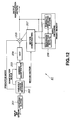
- This picture encoding apparatus comprises, as shown in FIG. 9, a pre-processing circuit 61 for separating an input video signal VD into luminance signal and color difference signal, analog/digital (hereinafter referred to as A/D) converting circuits 62a, 62b for respectively converting the luminance signal and the color difference signal from the pre-processing circuit 61 into digital signals, a frame memory group 63 for storing luminance data and color difference data (hereinafter referred to as picture data) from the A/D converting circuits 62a, 62b, a format converting circuit 64 for reading out picture data from the frame memory group 63 in accordance with block format, and an encoder 65 for implementing efficient coding to picture data of block from the format converting circuit 64.
- A/D analog/digital
- pre-processing circuit 61 separates input video signal VD into luminance signal and color difference signal.
- A/D converting circuits 62a, 62b respectively converts luminance signal and color difference signal into luminance data and color difference data each comprised of 8 bits.
- Frame memory group 63 stores these luminance and color difference data.
- Format converting circuit 64 reads out, in accordance with block format, picture data (luminance data, color difference data) stored in the frame memory group 63.
- Encoder 65 encodes the picture data thus read out by a predetermined efficient coding to output bit stream.
- This bit stream is delivered to picture decoding apparatus 80 through transmission media 70 comprised of transmission path or picture recording media such as, optical disc, magnetic disc or magnetic tape, etc.
- This picture decoding apparatus 80 comprises, as shown in the FIG. 9 mentioned above, decoder 81 corresponding to the encoder 65, format converting circuit 82 for converting picture data reproduced by the decoder 81 into frame format, frame memory groups 83 for storing picture data from the format converting circuit 82, D/A converting circuits 84a, 84b for converting luminance data, color difference data which have been read out from the frame memory group 83 into analog signals, and post-processing circuit 85 for mixing luminance signal, color difference signal from the D/A converting circuits 84a, 84b, thus to generate output video signal.
- Decoder 81 decodes bit stream by decoding corresponding to efficient coding of encoder 65 to reproduce picture data of block format.
- Format converting circuit 82 converts this picture data into frame format to store it into frame memory group 83.
- D/A converting circuits 84a, 84b respectively convert luminance data and color difference data which have been read out from frame memory group 83 into luminance signal and color difference signal.
- Post-processing circuit 81 mixes these luminance signal and color difference signal, thus to generate output video signal.
- pre-processing circuit 61 and A/D converting circuits 62a, 62b convert luminance signal and color difference signal into digital signal as described above to reduce quantity of data so that the numbers of pixels become equal to one half of those of luminance signal in upper and lower directions and in left and right directions with respect to the luminance signal thereafter to implement time axis multiplexing processing thereto to deliver luminance data and color difference data thus obtained to frame memory group 63.
- luminance data and color difference data are read out in accordance with block format as described above. Namely, e.g., picture data of one frame is divided into N slices as shown in FIG. 10A. Each slice is caused to include M macro blocks as shown in FIG. 10B. Each macro block is composed of luminance data Y1, Y2, Y3, Y4 of four luminance blocks consisting of 8x8 pixels adjacent in upper and lower directions and in left and right directions and color difference data Cb, Cr of color blocks consisting of 8x8 pixels in a range corresponding to these four luminance blocks.
- luminance data and color difference data are read out so that picture data are successive in macro block units within slice and are successive in order of Y1, Y2, Y3, Y4, Cb, Cr within macro block.
- Picture data which have been read out in accordance with block format in this way are delivered to encoder 65.
- Encoder 65 comprises motion vector detecting circuit 101 as shown in FIG. 11.
- This motion vector detecting circuit 101 detects, in macro block units, motion vector of picture data delivered thereto in accordance with block format. Namely, motion vector detecting circuit 101 detects, in macro block units, motion vector of current reference picture by forward original picture and/or backward original picture stored in frame memory group 63.
- detection of motion vector is carried out such that minimum one of absolute value sums of differences between frames in macro block units is caused to be corresponding motion vector.
- the motion vector thus detected is delivered to motion compensating circuit 113, etc., and intra-frame differences in macro block units are delivered to intra-frame/forward/backward bidirectionally predictive judging circuit 103.
- This intra-frame/forward/backward/bidirectionally predictive judging circuit 103 determines predictive mode of reference block on the basis of this value to control predictive coding circuit 104 so as to carry out switching of intra-frame/forward/backward/bidirectional prediction in macro block units.
- Predictive coding circuit 104 comprises adding circuits 104a, 104b, 104c and selecting (changeover) switch 104d, and is operative so that when predictive coding mode is intra-frame coding mode, it selects input picture itself, and when predictive coding mode is forward/backward/bidirectionally predictive mode, it selects differences (hereinafter referred to as difference data) every pixels of input picture data with respect to respective predictive pictures, thus to deliver the selected data to DCT circuit 105.
- DCT circuit 105 implements DCT processing to input picture data or difference data in block units by making use of the two-dimensional correlation of video signal to deliver coefficient data thus obtained to quantizing circuit 106.
- the quantizing circuit 106 quantizes coefficient data by using quantization step size (quantization scale) determined every macro block or slice to deliver quantized data thus obtained to variable length coding (hereinafter referred to as VLC) circuit 107 and inverse quantizing circuit 108. Meanwhile, quantization step size used for this quantization is determined so as to take a value such that transmitting buffer memory 109 which will be described later does not break by providing feedback of buffer residual of transmitting buffer 109. This quantization step size is also delivered to VLC circuit 107 and inverse quantizing circuit 108.
- quantization step size quantization scale
- VLC circuit 107 implements variable length coding to quantized data along with quantization step size, predictive mode and motion vector to deliver them to transmitting buffer memory 109 as transmit data.
- the transmitting buffer memory 109 temporarily stores transmit data thereafter to read out it at a predetermined bit rate to thereby smooth transmit data to output it as bit stream, and to feed quantization control signal in macro block units back to quantizing circuit 106 in accordance with residual data quantity remaining in the memory to control quantization step size.
- transmitting buffer memory 109 adjusts data quantity generated as bit strem to maintain data of appropriate residual (remaining capacity) (data quantity such that no overflow or underflow takes place) within the memory. For example, when data residual of transmitting buffer memory 109 increase to allowed upper limit, transmitting buffer memory 109 allows quantization step size of quantizing circuit 106 to be large by quantization control signal, thus to reduce data quantity of quantized data. On the other hand, when data residual of transmit buffer memory 109 decrease down to allowed lower limit, transmitting buffer memory 109 allows quantization step size of quantizing cirucit 106 to be small by quantization control signal to thereby increase data quantity.
- bit stream outputted from buffer memory 109 is delivered to picture decoded unit 80 through transmission media 70 comprised of a transmission path or a picture recording medium such as optical disc, magnetic disc, or magnetic tape etc. at a predetermined bit rate as described above.
- inverse quantizing circuit 108 inverse-quantizes quantized data delivered from quantizing circuit 106 to reproduce coefficient data (quantization distortion is added) corresponding to output of the about-described DCT circuit 105 to deliver the coefficient data to Inverse Discrete Cosine Transform (hereinafter referred to as IDCT) circuit 110.
- IDCT Inverse Discrete Cosine Transform
- the IDCT circuit 110 implements IDCT processing to the coefficient data to reproduce picture data corresponding to input picture data in the intra-frame coding mode, and to reproduce difference data corresponding to output of predictive coding circuit 104 in the forward/backward/bidirectionally predictive modes, thus to deliver it to adding circuit 111.
- the adding circuit 111 is supplied with motion-compensated predictive picture data from motion compensating circuit 113 which will be described later to described later to add the motion-compensated predictive picture data and difference data to thereby reproduce picture data corresponding to input picture data.
- inverse quantizing circuit 108 ⁇ adding circuit 111 constitute a local decoding circuit to locally decode quantized data outputted from quantizing circuit 106 to write decoded picture thus obtained into frame memory 112 as forward predictive picture or backward predictive picture.
- the frame memory 112 is comprised of a plurality of frame memories. Bank switching of the frame memory is carried out.
- single frame is outputted as forward predictive picture data, or is outputted as backward predictive picture data.
- forward predictive picture data and backward predictive picture data are, e.g., averaged. The averaged data thus obtained is outputted.
- These predictive picture data are entirely the same pictures as pictures reproduced by decoder 81 which will be described later. Picture to be processed next is caused to undergo forward/backward/bidirectional predictive coding on the basis of this predictive picture.
- picture data which has been read out from frame memory 112 is delivered to motion compensating circuit 113.
- This motion compensating circuit 113 implements motion compensation to predictive picture data on the basis of motion vector to deliver the motion-compensated predictive picture data to predictive encoding circuit 104 and adding circuit 111.
- Decoder 81 will now be described.
- bit stream is inputted through transmission media 70 is inputted.
- This bit stream is inputted to Variable Length Decoding (Inverse Variable Length Coding) (hereinafter referred to as IVLC) through receiving buffer 201.
- the IVLC circuit 202 reproduces quantized data, motion vector, predictive mode and quantization step size, etc. from bit stream. These quantized data and quantization step size are delivered to inverse quantizing circuit 203.
- Motion vector is delivered to motion compensating circuit 207, and predictive mode is delivered to adding circuit 205.
- inverse quantizing circuit 203 ⁇ adding circuit 205 is the same as that of local decoding circuit of encoder 61, the operations of frame memory group 206, motion compensating circuit 207 are respectively the same as those of frame memory 112 and motion compensating circuit 113 of encoder 61.
- decoding is carried out. As a result, reproduction picture data is outputted from adding circuit 205.
- coding bit rate of bit stream generated at encoder 65 is caused to be fixed in correspondence with transfer rate of transmission media 70.
- quantity of data generated i.e., quantization step size of quantizing circuit 106 in encoder 65 was controlled.
- a control was conducted such that when pictures of complicated pattern are successive, quantization step size is caused to be larger to suppress quantity of data generated, while when simple patterns are successive, quantization step size is caused to be smaller to increase quantity of data generated so that buffer memory 109 does not produce overflow or underflow, thus to maintain a fixed rate.
- EP-A-0 475 251 discloses a method of encoding source video data in which the source video data is DCT transformed, quantized and variable length encoded to generate first encoded data and the coding amount (number of bits) in a block of the encoded data is detected. An optimum quantizing level is selected based on the number of bits. The DCT transferred signal is quantized again - using the optimum quantizing level - and variable length coded again. The optimum quantizing level is decided such that, as the number of bits becomes larger, the quantizing step width is made coarser.
- EP-A-0 509 576 discloses a method of encoding source video data in which quantizing factors are selected to limit the quantizing noise introduced when performing multi-generations of data quantizing and de-quantizing on the basis that the complexity of the image represented by the data will change in selected generations. Specifically, an optimum quantizing factor which will compress the data sufficiently to fit into an allotted space is chosen, as is also an over-quantizing factor which is larger than the quantizing factor and is selected as a function of the expected cumulative change in image data complexity performed in subsequent generations.
- a method of encoding source video data comprising the steps of:
- apparatus for encoding source video data comprising:
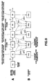
- a picture encoding apparatus to which this invention is applied comprises, as shown in FIG. 1, for example, a first encoding circuit 10 for encoding an input video signal to generate first encoded data, an encoding control circuit 30 for determining encoding rate every predetermined time on the basis of data quantity every predetermined time of the first encoded data from the first encoding circuit 10 and total quantity of usable data, and a second encoding circuit 40 for encoding the input video signal every predetermined time on the basis of the encoding rate from the encoding control circuit 30 to generate second encoded data.
- the first encoding circuit 10 comprises, as shown in the FIG. 1 mentioned above, a frame memory group 12 for storing input picture data which is input video signal, a motion vector detecting circuit 11 for detecting motion vector of input picture data from input picture data on the basis of picture data stored in the frame memory group 12, a frame memory 22 for storing predictive picture data, a motion compensating circuit 23 for implementing motion compensation to predictive picture data which has been read out from the frame memory 22 on the basis of motion vector from the motion vector detecting circuit 11, a predictive encoding circuit 14 for predictive-encoding input picture data on the basis of motion-compensated predictive picture data from the motion compensating circuit 23, a DCT circuit 15 for implementing encoding, e.g., Discrete Cosine Transform (hereinafter referred to as DCT) processing to differences, etc.
- DCT Discrete Cosine Transform
- VLC Variable Length Code
- IDCT Inverse Discrete Cosine Transform
- the second encoding circuit 40 comprises, as shown in the FIG. 1 mentioned above, a delay element 43 for delaying input picture data, a frame memory 52 for storing predictive picture data, a motion compensating circuit 53 for implementing motion compensation to predictive picture data which has been read out from the frame memory 52 on the basis of motion vector from the motion vector detecting circuit 11, a predictive encoding circuit 44 for predictive-encoding input picture data delayed at the delay element 43 on the basis of the motion compensated predictive picture data from the motion compensating circuit 53, a DCT circuit 45 for implementing encoding, e.g., DCT processing to difference, etc.
- a delay element 43 for delaying input picture data
- a frame memory 52 for storing predictive picture data
- a motion compensating circuit 53 for implementing motion compensation to predictive picture data which has been read out from the frame memory 52 on the basis of motion vector from the motion vector detecting circuit 11
- a predictive encoding circuit 44 for predictive-encoding input picture data delayed at the delay element 43 on the basis of the motion compensated predictive picture data
- a quantization scale setting circuit 33 for setting quantization step size on the basis of encoding rate from the encoding control circuit 30, a quantizing circuit 46 for quantizing coefficient data from the DCT circuit 45 at quantization step size from the quantization scale setting circuit 33, a VLC circuit for allowing quantized data from the quantizing circuit 46 to undergo variable length encoding to output variable length encoded data, a transmitting buffer memory 49 for temporarily storing variable length encoded data from the VLC circuit 47 to output it at a fixed bit rate, an inverse quantizing circuit 48 for inverse-quantizing quantized data from the quantizing circuit 46 to reproduce coefficient data, an IDCT circuit 50 for implementing decoding, e.g., IDCT processing to the coefficient data from the inverse quantizing circuit 48 to reproduce the difference, and an adding circuit 51 for adding difference from the IDCT circuit 50 and the motion-compensated predictive picture data from the motion compensating circuit 53 to generate predictive picture data with respect to the next input picture data to deliver the predictive picture data to the frame
- encoding processing e.g., predictive encoding processing, DCT processing, quantization processing at fixed quantization step size and variable length encoding processing are implemented to input picture data.
- encoding control circuit 30 encoding bit rate is determined on the basis of data quantity every predetermined time of variable length encoded data which is the first bit stream obtained and data capacity of picture recording medium 55, e.g., comprised of optical disc, magnetic disc or magnetic tape, etc. or total quantity of usable data determined by bit rate of transmission path (transfer rate).
- second encoding circuit 40 predictive encoding processing, DCT processing, quantization processing and variable length encoding processing are implemented to input picture data for a second time.
- quantization is made by quantization step size based on encoding bit rate.
- quantizing circuit 16 of first encoding circuit 10 sets quantization step size to, e.g., 1 to quantize coefficient data delivered from DCT circuit 15 to generate quantized data.
- Counter 31 of encoding control circuit 30 counts data quantity of variable length encoded data (first bit stream) obtained by allowing the quantized data to undergo variable length encoding every predetermined time, e.g., one frame to determine, every frame, quantity of code generated indicating difficulty of encoding.
- bit rate calculating circuit 32 determines allocated code quantity allocated every frame on the basis of difficulty (quantity of code generated) every frame and total quantity of usable data.
- quantizing circuit 46 of second encoding circuit 40 quantizes coefficient data delivered from DCT circuit 45 by quantization step size based on allocated code quantity to generate quantized data.
- inputted picture data is temporarily stored into frame memory group 12. From the frame memory group 12, that picture data is read out in accordance with block format as described in the prior art.
- Motion vector detecting circuit 11 reads out necessary picture data from frame memory group 12 in macro block units described above to detect motion vector. Namely, motion vector detecting circuit 11 detects, in macro block units, motion vector of current reference picture by using forward original picture and/or backward original picture stored in frame memory group 12. Here, detection of motion vector is carried out such that a motion vector in which, e.g., absolute value sum of differences between frames in macro block units becomes minimum is caused to be corresponding motion vector.
- the detected motion vector is delivered to motion compensating circuits 23, 53, etc., and absolute value sum of differences between frames in macro block units is delivered to intra-frame/forward/backward/bidirectionally predictive judging circuit 13.
- the intra-frame/forward/backward/bidirectionally predictive judging circuit 13 determines predictive mode on the basis of the above value to control predictive encoding circuit 14 so as to carry out switching of intra-frame/forward/backward/bidirectional prediction in block units.
- the predictive encoding circuit 14 comprises, as shown in FIG. 1 mentioned above, adding circuits 14a, 14b, 14c and selecting (changeover) switch 14d.
- the selecting switch 14d select input picture data itself, and when predictive encoding mode is forward/backward/bidirectionally predictive mode, it selects differences (hereinafter referred to as difference data) every pixels of input picture data with respect to respective predictive pictures. Then, the selecting switch 14d delivers selected data to DCT circuit 15.
- the DCT circuit 15 implements, in block units, DCT processing to input picture data or difference data delivered from selecting switch 14d by making use of the two-dimensional correlation of video signal to deliver coefficient data thus obtained to quantizing circuit 16.
- the quantizing circuit 16 quantizes coefficient data delivered from DCT circuit 15 at a fixed quantization step size, e.g., with quantization step size being set to 1 to deliver quantized data thus obtained to VLC circuit 17 and inverse quantizing circuit 18.
- the VLC circuit 17 carries out variable length encoding of quantized data along with quantization step size, predictive mode, and motion vector, etc. to deliver variable length encoded data obtained to encoding control circuit 30 as a first bit stream.
- the encoding control circuit 30 comprises, as shown in the FIG. 1 mentioned above, counter 31 for counting data quantity every predetermined time of variable length encoded data from the VLC circuit 17, and bit rate calculating circuit 32 for calculating (determining) allocated code quantity per unit time on the basis of data quantity from the counter 31 and total quantity of usable data.
- the counter 31 counts data quantity of the first bit stream every predetermined time, e.g., every one frame to determine (calculates) difficulty every frame to deliver this difficulty to bit rate calculating circuit 32.
- the bit rate calculating circuit 32 calculates (determines) allocated code quantity allocated every frame, i.e., mean encoding rate every frame time on the basis of difficulty every frame and total quantity of usable data, and delivers this allocated code quantity to quantization scale setting circuit 33 of second encoding circuit 40.
- constant a can be calculated by the following formula (3).
- allocated code quantity b i with respect to the i-th frame can be calculated by the following formula (4).
- bit rate calculating circuit 32 increases allocated code quantity b i with respect to frame of picture of complicated pattern, for example, and decreases allocated code quantity b i with respect to frame of simple pattern.
- inverse quantizing circuit 18 inverse-quantizes quantized data delivered from quantizing circuit 16 at quantization step size caused to be set to 1 to reproduce coefficient data (quantization distortion is added) corresponding to output of DCT circuit 15 to deliver that coefficient data to IDCT circuit 20.
- the IDCT circuit 20 implements IDCT processing to coefficient data to reproduce input picture data corresponding to output of predictive encoding circuit 14 in the intra-frame encoding mode, and reproduces difference data in the forward/backward/bidirectionally predictive mode, thus to deliver reproduced data to adding circuit 21.
- the adding circuit 21 is supplied, when predictive encoding mode is forward/backward/bidirectionally predictive mode, with motion-compensated predictive picture data from motion compensating circuit 23.
- the adding circuit 21 adds this predictive picture data and difference data delivered from IDCT circuit 20 to thereby reproduce picture data corresponding to input picture data.
- the picture data reproduced in this way is stored into frame memory 22 as predictive picture data.
- inverse quantizing circuit 18 ⁇ adding circuit 21 constitute a local decoding circuit to locally decode quantized data outputted from quantizing circuit 16 on the basis of predictive mode to write decoded picture obtained into frame memory 22 as forward predictive picture or backward predictive picture.
- Frame memory 22 is composed of a plurality of frame memories. Bank switching of frame memory is carried out. In dependency upon picture to be encoded, e.g., single frame is outputted as forward predictive picture data, or is outputted as backward predictive picture data. Further, in the case of forward/backward/bidirectional prediction, forward predictive picture data and backward predictive picture data are, e.g., averaged and the averaged data is outputted. These predictive picture data are entirely the same picture data as picture data reproduced by picture decoding apparatus which will be described later. Picture to be processed next is caused to undergo forward/backward/bidirectionally encoding on the basis of this predictive picture.
- second encoding circuit 40 The operation of second encoding circuit 40 will now be described. It is to be noted that since circuits except for quantization scale setting circuit 33, delay element 43, quantizing circuit 46, and transmitting buffer 49 constituting second encoding circuit 40 perform the same operations as those of circuits constituting the above-described first encoding circuit 10, their explanation is omitted.
- Delay element 43 delays input picture data, e.g., by time until encoding control signal is outputted from encoding control circuit 30. Then, at predictive encoding circuit 44 and DCT circuit 45, predictive encoding processing and DCT processing which are in accordance with predictive mode delivered from intra-frame/forward/backward/bidirectionally predictive judging circuit 13 are implemented to the delayed input picture data. Thus, coefficient data is generated.
- Quantization scale setting circuit 33 determines (calculates) allocated code quantity every macro block (e.g., value obtained by dividing allocated code quantity every frame by the number of macro blocks in one frame) from delivered allocated code quantity every frame to carry out comparison between code quantity generated in a macro block which is detected from buffer feedback from transmitting buffer 49 and allocated code quantity every macro block.
- the quantization scale setting circuit 33 operates as follows so as to allow encoding bit rates of respective frames to become close to set mean encoding bit rate every frame time. Namely, in the case where code quantity generated in corresponding macro block is greater than allocated code quantity every macro block, the circuit 33 sets quantization step size of next macro block to a greater value in order to suppress code quantity generated by the next macro block.
- quantization scale setting circuit 33 is operative so that in the case where buffer feedback from transmitting buffer 49 indicates that transmitting buffer 49 is in a state close to overflow state, it allows quantization step size to be larger to suppress overflow irrespective of comparison result between the allocated code quantity and code quantity generated, while in the case where buffer feedback from the transmitting buffer 49 indicates that transmitting buffer 49 is in a state close to underflow state, it allows quantization step to be smaller to suppress underflow irrespective of comparison result between the allocated code quantity and code quantity generated.
- the quantizing circuit 46 quantizes coefficient data delivered from DCT circuit 45 by quantization step size delivered from the above-described quantization scale setting circuit 33 to generate quantized data.
- VLC circuit 47 allows quantized data delivered from quantizing circuit 46 to undergo variable length encoding along with quantization step size from quantization scale setting circuit 33, predictive mode from intra-frame/forward/backward/bidirectionally predictive judging circuit 13, and motion vector from motion vector detecting circuit 11, etc. to deliver variable length encoded data obtained to transmitting buffer memory 49 as a second bit stream.
- quantization scale setting circuit 33 reads in, from encoding control circuit 30, allocated code quantity with respect to frame to be currently encoded at step ST2, then, the processing operation proceeds to step ST3.
- step ST3 predictive encoding circuit 44 ⁇ VLC circuit 47 implement predictive encoding processing and DCT processing to picture data, and quantizes coefficient data by quantization step size based on allocated code quantity thereafter to allow it to undergo variable length encoding. Then, the processing operation proceeds to step ST4.
- step ST4 whether or not encoding processing has been completed with respect to all frames (sequence) to which, e.g., the same picture size or the same transfer rate is applied is judged. If so, the processing is completed. In contrast, if not so, the processing operation returns to step ST1.
- variable rate encoding such that encoding rate changes in frame units is realized. Accordingly, even if pictures (frames) of complicated pattern are successive, there is no possibility that quantization step size is caused to be large with respect to these pictures as in the conventional apparatus. Thus, uniform high picture quality can be obtained through the entirety.
- the transmitting buffer memory 49 temporarily stores variable length encoded data thereafter to read out it at a fixed bit rate to thereby smooth the variable length encoded data to output it as bit stream.
- the bit stream which has been outputted from transmitting buffer 49 is multiplexed along with, e.g., encoded audio signal, synchronizing signal, etc. Further, code for error correction is added thereto, and a predetermined modulation suitable for transmission or recording is applied thereto. Thereafter, bit stream thus processed is transmitted to picture decoding apparatus through, e.g., transmission path, or is recorded onto picture recording medium 55 comprised of optical disc, magnetic disc or magnetic tape, etc. as shown in the FIG. 1 mentioned above.
- inverse quantizing circuit 48 inverse-quantizes quantized data delivered from quantizing circuit 46 by quantization step size used in the above-described quantizing circuit 46 to reproduce coefficient data (quantization distortion is added) corresponding to output of DCT circuit 45 to deliver this coefficient data to IDCT circuit 50.
- inverse quantizing circuit 48 ⁇ adding circuit 51 constituting a local decoding circuit locally decode quantized data outputted from quantizing circuit 46 to write decoded picture obtained into frame memory 52 as forward predictive picture or backward predictive picture. Picture data stored in frame memory 52 is used as predictive picture for picture to be processed next.
- allocated code quantity per predetermined time i.e., mean encoding rate per predetermined time is obtained every frame with frame being used as predetermined time
- this invention is not limited to such an implementation.
- GOP Group of Pictures in so called MPEG (Moving Picture Expert Group) may be used as a predetermined time.
- MPEG Motion Picture Expert Group
- the above-described MPEG is general name of the moving picture encoding system being studied in WG (Working Group) 11 of SC (Sub Committee) 29 in JTC (Joint Technical Committee) of so called ISO (International Standardization Organization) and IEC (International Electrotechnical Committee).
- GOP in MPEG consists of at least one so called I picture, and a plurality of P pictures or B pictures (non-I picture).
- encoding control circuit 30 determines allocated code quantity every GOP.
- I picture is picture to be subjected to intra-field or intra-frame encoding.
- P picture is picture which can be predicted only from forward direction, and is subjected to interfield or intra-frame encoding.
- B picture is picture which can be predicted from forward direction, from back ward direction and from both directions and is subjected to interfield or intra-frame encoding.
- the first encoding circuit 10 implements predictive encoding processing, DCT processing, and variable length encoding processing to picture data of these I and P pictures to generate variable length encoded data to deliver the variable length encoded data to encoding control circuit 30.
- the reason why two pictures are used as I picture, P picture is to examine complexity of pattern and correlation between frames. From code quantity generated of I picture, it is possible to recognize complexity of pattern. From code quantity generated of P picture, it is possible to recognize correlation between frames. Since successive plural frames have similar pictorial images in general, it is possible to recognize tendency of pattern of GOP even from extracted two pictures.
- GOPd i bitI j + N ⁇ bitP j
- the encoding control circuit 30 determines allocated code quantity allocated every GOP on the basis of difficulty (code quantity generated) GOP dj every GOP and total quantity of usable data, and delivers this allocated code quantity to second encoding circuit 40.
- constant a can be determined by the following formula (8). Substituting this constant a into the formula (6), allocated code quantity GOPbj with respect to the j-th GOP can be determined by the following formula (9).
- encoding control circuit 30 increases allocated code quantity GOP b j with respect to, e.g., GOP in which pictures of complicated pattern are included or having low correlation between frames, and decreases allocated code quantity GOP b j with respect to GOP in which pictures of simple pattern are included or having high correlation between frames.
- second encoding circuit 40 When second encoding circuit 40 is supplied with picture data through delay element 43 at step ST1, as shown in FIG. 6, for example, it judges whether or not picture data being inputted is the leading picture of GOP. If so, the processing operation proceeds to step ST3. If not so, the processing operation proceeds to step ST4.
- step ST3 second encoding circuit 40 reads in allocated code quantity with respect to GOP currently subjected to encoding from encoding control circuit 30. Then, the processing operation proceeds to step ST4.
- second encoding circuit 40 implements predictive encoding processing and DCT processing, and quantizes coefficient data by quantization step size based on allocated code quantity thereafter to allow it to undergo variable length encoding. Then, the processing operation proceeds to step ST5.
- quantization scale setting circuit 33 sets allocated code quantity every frame from delivered allocated code quantity every GOP by taking into consideration picture type (I picture, P picture, B picture) in actual encoding, e.g., picture type shown in FIG. 4.
- picture type I picture, P picture, B picture
- allocated code quantity with respect to I picture is increased, allocated code quantity with respect to B picture is decreased, and allocated code quantity with respect to P picture is caused to be intermediate therebetween.
- step ST5 whether or not encoding processing has been completed with respect to all frames (sequence) to which the same picture size or the same transfer rate is applied is judged. If so, the processing is completed. In contrast, if not so, the processing operation returns to step ST1.
- a variable rate encoding such that encoding rate changes every GOP is realized. Even if pictures (frames) of complicated pattern are successive, there is no possibility that quantization step size is caused to be large with respect to these pictures as in the conventional apparatus. As a result, it is possible to obtain uniform high picture quality over the entirety. Further, since allocated code quantity every GOP is determined on the basis of two pictures in this embodiment, higher speed processing can be carried out as compared to the above-described emboidment. It is to be noted that it is a matter of course to determine allocated code quantities of respective GOPs on the basis of data quantities of all pictures within GOP.
- transform coding employs DCT in the above-described embodiments, so called Strato transform, Haar transform or Wavelet transform, etc. may be employed.
- this invention employs a scheme to allow an input video signal to undergo encoding, e.g., predictive encoding, DCT processing, quantization at fixed quantization step size and variable length encoding to generate first encoded data to determine (calculate) allocated code quantity every frame or every GOP on the basis of data quantity every predetermined time, e.g., every frame or every GOP of the first encoded data and total quantity of usable data to encode the input video signal every predetermined time on the basis of the allocated code quantity to generate second encoded data.
- variable rate encoding such that encoding rate changes every predetermined time is realized.
- second encoded data obtained in a manner as described above has variable rate, in the case where such encoded data is recorded onto picture recording media, limited memory capacity can be effectively used, and recording time of picture recording media can be prolonged. In addition, picture data of high picture quality uniform through the entirety can be reproduced from the picture recording media.
Description
- This invention relates to encoding source video data. A preferred form of implementation of the invention described hereinbelow provides a picture encoding method and apparatus which are used in a system for implementing encoding for storage to a video signal of a moving picture to record the coded signal onto a picture recording medium such as an optical disc, a magnetic disc, or a magnetic tape, etc., or a system for transmitting a video signal of a moving picture through a transmission path.
- Hitherto, in a system for transmitting a video signal of a moving picture to a remote place, for example, as in the television conference system, the television telephone system, etc., or a system for recording a video signal of moving picture onto a picture recording medium such as an optical disc, a magnetic disc or magnetic tape, etc., or reproducing a recorded video signal of moving picture, there is adopted for the purpose of efficiently utilizing transmission path (or picture recording medium), a scheme to implement so called efficient encoding to a video signal by making use of correlation between lines or correlation between frames that video signal has to reduce redundancies in the spatial axis direction and the time axis direction to transmit only significant information, thus to improve transmission efficiency.
- For example, in encoding processing in the spatial axis direction (hereinafter intra-frame coding processing), e.g., correlation between lines of a video signal is utilized as shown in FIG. 7A. In the case of attempting to transmit respective pictures PC1, PC2, PC3 ··· constituting a moving picture at times t1, t2, t3 ···, picture data to be transmission-processed is caused to undergo one-dimensional coding, e.g., within the same scanning line, or a picture is divided into, e.g., a plurality of blocks to allow picture data of respective blocks to undergo two-dimensional coding to thereby carry out data compression, thus to improve transmission efficiency.
- Moreover, in coding processing in the time axis direction (hereinafter referred to as intra-frame coding processing), intra-frame correlation of video signal is utilized to determine, by so called predictive coding, for example, picture data PC12, PC23 ··· comprised of deficiencies (so called predictive errors) of picture data every corresponding pixels between adjacent pictures PC1 and PC2, PC2 and PC3 ··· in succession to transmit these picture data PC12, PC23, ··· to thereby carry out data compression, thus to improve transmission efficiency.
- Thus, as compared to the case where all picture data of pictures PC1, PC2, PC3 ··· are transmitted, a video signal can be transmitted by extremely lesser data quantity.
- Further, in the predictive coding in the above-described intra-frame coding processing, motion compensated prediction is used, e.g., in macro block units in order to further improve efficiency. Namely, e.g., in the case where a person at the central portion of picture moves, or the like, motion (movement) of an object moving in the picture is detected to correct position of picture data used for prediction in the former picture by that motion to carry out predictive coding, thereby making it possible to improve coding efficiency. However, even when such motion compensated prediction is employed, many data must be transmitted with respect to the portion where an object moves and appears from behind. In view of this, not only motion compensation in the above-described forward direction, but also motion compensation in backward direction or in both directions of forward and backward directions are carried out in combination, thereby making it possible to further improve coding efficiency.
- In actual terms, as shown in FIG. 8A, in macro blocks of frame data F0, F1, F2, F3 of the 0th, first, second, third ··· frames of a video signal of moving picture to be transmitted, in the case where there took place changes of pictures as respectively indicated by motion vectors x0, x1, x2, x3 ··· between frames in succession, device on the transmitter side designates frames at intervals of a predetermined number of frames (e.g., every other frame), i.e., second, fourth ··· frames as interpolation frame to implement so called predetermined interpolation frame processing to these interpolation frames as shown in FIG. 8B to thereby generate transmit interpolated frame data F2X, F4X ··· Further, with respect to non-interpolation frames, the device on the transmitting side implements a predetermined coding processing to frame data F1, F3 ··· to generate transmit non-interpolated frame data F1X, F3X ···.
- For example, difference SP2 (predictive error) between motion compensated frame data F3 and F2, difference SP3 between motion compensated frame data F1 and F2, and difference SP4 between frame data obtained by implementing interpolation processing to motion compensated frame data F1, F3 and frame data F2 are respectively determined in macro block units to compare difference (data) SP1 of frame data F2 and those differences. Then, data having minimum data quantity generated of those data SP1 ∼ SP4 is caused to be transmit interpolated data F2X in macro block units. Similarly, transmit interpolated data F4X ··· with respect to respective interpolation frames are generated. Further, e.g., DCT processing and variable length coding processing, etc. are implemented to frame data F1, F3 ··· of non-interpolation frames to generate transmit non-interpolated frame data F1X, F3X ···.
- The transmit non-interpolated frame data F1X, F3X ··· and transmit interpolated frame data F2X, F4X ··· are transmitted to the device on the receiving side as transmit data along with motion vectors x0, x1, x3 ···.
- On the other hand, the device on the receiving side implements decoding processing corresponding to coding processing on the transmitting side to transmit data (transmit non-interpolated frame data F1X, F3X ···, transmit interpolated frame data F2X, F4X ···, data of motion vectors x0, x1, x3 ···), thus to reproduce frame data F0, F1, F2, F3 ···. As a result, motion compensation is implemented not only in forward direction but also in backward direction or in forward and backward directions, thereby making it possible to further improve coding efficiency.
- Picture encoding apparatus and picture decoding apparatus having the above-described function will now be described.
- This picture encoding apparatus comprises, as shown in FIG. 9, a
pre-processing circuit 61 for separating an input video signal VD into luminance signal and color difference signal, analog/digital (hereinafter referred to as A/D) convertingcircuits pre-processing circuit 61 into digital signals, aframe memory group 63 for storing luminance data and color difference data (hereinafter referred to as picture data) from the A/D converting circuits format converting circuit 64 for reading out picture data from theframe memory group 63 in accordance with block format, and anencoder 65 for implementing efficient coding to picture data of block from theformat converting circuit 64. - In operation, pre-processing
circuit 61 separates input video signal VD into luminance signal and color difference signal. A/D converting circuits Frame memory group 63 stores these luminance and color difference data. -
Format converting circuit 64 reads out, in accordance with block format, picture data (luminance data, color difference data) stored in theframe memory group 63.Encoder 65 encodes the picture data thus read out by a predetermined efficient coding to output bit stream. - This bit stream is delivered to
picture decoding apparatus 80 throughtransmission media 70 comprised of transmission path or picture recording media such as, optical disc, magnetic disc or magnetic tape, etc. - This
picture decoding apparatus 80 comprises, as shown in the FIG. 9 mentioned above,decoder 81 corresponding to theencoder 65,format converting circuit 82 for converting picture data reproduced by thedecoder 81 into frame format,frame memory groups 83 for storing picture data from theformat converting circuit 82, D/A converting circuits frame memory group 83 into analog signals, andpost-processing circuit 85 for mixing luminance signal, color difference signal from the D/A converting circuits -
Decoder 81 decodes bit stream by decoding corresponding to efficient coding ofencoder 65 to reproduce picture data of block format. Format convertingcircuit 82 converts this picture data into frame format to store it intoframe memory group 83. - D/A converting
circuits frame memory group 83 into luminance signal and color difference signal.Post-processing circuit 81 mixes these luminance signal and color difference signal, thus to generate output video signal. - In actual terms, pre-processing
circuit 61 and A/D converting circuits memory group 63. - From
frame memory group 63, luminance data and color difference data are read out in accordance with block format as described above. Namely, e.g., picture data of one frame is divided into N slices as shown in FIG. 10A. Each slice is caused to include M macro blocks as shown in FIG. 10B. Each macro block is composed of luminance data Y1, Y2, Y3, Y4 of four luminance blocks consisting of 8x8 pixels adjacent in upper and lower directions and in left and right directions and color difference data Cb, Cr of color blocks consisting of 8x8 pixels in a range corresponding to these four luminance blocks. Fromframe memory group 63, luminance data and color difference data are read out so that picture data are successive in macro block units within slice and are successive in order of Y1, Y2, Y3, Y4, Cb, Cr within macro block. Picture data which have been read out in accordance with block format in this way are delivered toencoder 65. -
Encoder 65 comprises motionvector detecting circuit 101 as shown in FIG. 11. This motionvector detecting circuit 101 detects, in macro block units, motion vector of picture data delivered thereto in accordance with block format. Namely, motionvector detecting circuit 101 detects, in macro block units, motion vector of current reference picture by forward original picture and/or backward original picture stored inframe memory group 63. Here, detection of motion vector is carried out such that minimum one of absolute value sums of differences between frames in macro block units is caused to be corresponding motion vector. The motion vector thus detected is delivered tomotion compensating circuit 113, etc., and intra-frame differences in macro block units are delivered to intra-frame/forward/backward bidirectionally predictive judgingcircuit 103. - This intra-frame/forward/backward/bidirectionally predictive judging
circuit 103 determines predictive mode of reference block on the basis of this value to controlpredictive coding circuit 104 so as to carry out switching of intra-frame/forward/backward/bidirectional prediction in macro block units.Predictive coding circuit 104 comprises addingcircuits switch 104d, and is operative so that when predictive coding mode is intra-frame coding mode, it selects input picture itself, and when predictive coding mode is forward/backward/bidirectionally predictive mode, it selects differences (hereinafter referred to as difference data) every pixels of input picture data with respect to respective predictive pictures, thus to deliver the selected data toDCT circuit 105. -
DCT circuit 105 implements DCT processing to input picture data or difference data in block units by making use of the two-dimensional correlation of video signal to deliver coefficient data thus obtained toquantizing circuit 106. - The
quantizing circuit 106 quantizes coefficient data by using quantization step size (quantization scale) determined every macro block or slice to deliver quantized data thus obtained to variable length coding (hereinafter referred to as VLC)circuit 107 andinverse quantizing circuit 108. Meanwhile, quantization step size used for this quantization is determined so as to take a value such that transmittingbuffer memory 109 which will be described later does not break by providing feedback of buffer residual of transmittingbuffer 109. This quantization step size is also delivered toVLC circuit 107 andinverse quantizing circuit 108. -
VLC circuit 107 implements variable length coding to quantized data along with quantization step size, predictive mode and motion vector to deliver them to transmittingbuffer memory 109 as transmit data. - The transmitting
buffer memory 109 temporarily stores transmit data thereafter to read out it at a predetermined bit rate to thereby smooth transmit data to output it as bit stream, and to feed quantization control signal in macro block units back toquantizing circuit 106 in accordance with residual data quantity remaining in the memory to control quantization step size. Thus, transmittingbuffer memory 109 adjusts data quantity generated as bit strem to maintain data of appropriate residual (remaining capacity) (data quantity such that no overflow or underflow takes place) within the memory. For example, when data residual of transmittingbuffer memory 109 increase to allowed upper limit, transmittingbuffer memory 109 allows quantization step size ofquantizing circuit 106 to be large by quantization control signal, thus to reduce data quantity of quantized data. On the other hand, when data residual of transmitbuffer memory 109 decrease down to allowed lower limit, transmittingbuffer memory 109 allows quantization step size ofquantizing cirucit 106 to be small by quantization control signal to thereby increase data quantity. - In this way, bit stream outputted from
buffer memory 109 is delivered to picture decodedunit 80 throughtransmission media 70 comprised of a transmission path or a picture recording medium such as optical disc, magnetic disc, or magnetic tape etc. at a predetermined bit rate as described above. - On the other hand,
inverse quantizing circuit 108 inverse-quantizes quantized data delivered from quantizingcircuit 106 to reproduce coefficient data (quantization distortion is added) corresponding to output of the about-describedDCT circuit 105 to deliver the coefficient data to Inverse Discrete Cosine Transform (hereinafter referred to as IDCT) circuit 110. - The IDCT circuit 110 implements IDCT processing to the coefficient data to reproduce picture data corresponding to input picture data in the intra-frame coding mode, and to reproduce difference data corresponding to output of
predictive coding circuit 104 in the forward/backward/bidirectionally predictive modes, thus to deliver it to addingcircuit 111. - When predictive coding mode is the forward/backward/bidirectionally predictive modes, the adding
circuit 111 is supplied with motion-compensated predictive picture data frommotion compensating circuit 113 which will be described later to described later to add the motion-compensated predictive picture data and difference data to thereby reproduce picture data corresponding to input picture data. - The picture data reproduced in this way is stored into
frame memory 112. Namely,inverse quantizing circuit 108 ∼ addingcircuit 111 constitute a local decoding circuit to locally decode quantized data outputted from quantizingcircuit 106 to write decoded picture thus obtained intoframe memory 112 as forward predictive picture or backward predictive picture. Theframe memory 112 is comprised of a plurality of frame memories. Bank switching of the frame memory is carried out. In correspondence with picture to be encoded, single frame is outputted as forward predictive picture data, or is outputted as backward predictive picture data. Moreover, in the case of bidirectional prediction, forward predictive picture data and backward predictive picture data are, e.g., averaged. The averaged data thus obtained is outputted. These predictive picture data are entirely the same pictures as pictures reproduced bydecoder 81 which will be described later. Picture to be processed next is caused to undergo forward/backward/bidirectional predictive coding on the basis of this predictive picture. - Namely, picture data which has been read out from
frame memory 112 is delivered tomotion compensating circuit 113. Thismotion compensating circuit 113 implements motion compensation to predictive picture data on the basis of motion vector to deliver the motion-compensated predictive picture data topredictive encoding circuit 104 and addingcircuit 111. -
Decoder 81 will now be described. - To
decoder 81, bit stream is inputted throughtransmission media 70 is inputted. This bit stream is inputted to Variable Length Decoding (Inverse Variable Length Coding) (hereinafter referred to as IVLC) through receivingbuffer 201. TheIVLC circuit 202 reproduces quantized data, motion vector, predictive mode and quantization step size, etc. from bit stream. These quantized data and quantization step size are delivered toinverse quantizing circuit 203. Motion vector is delivered tomotion compensating circuit 207, and predictive mode is delivered to addingcircuit 205. - The operation of
inverse quantizing circuit 203 ∼ addingcircuit 205 is the same as that of local decoding circuit ofencoder 61, the operations offrame memory group 206,motion compensating circuit 207 are respectively the same as those offrame memory 112 andmotion compensating circuit 113 ofencoder 61. On the basis of quantized data, motion vector, predictive mode, quantization step size, decoding is carried out. As a result, reproduction picture data is outputted from addingcircuit 205. - As described above, in the conventional apparatus, coding bit rate of bit stream generated at
encoder 65 is caused to be fixed in correspondence with transfer rate oftransmission media 70. Under this limitation, quantity of data generated, i.e., quantization step size ofquantizing circuit 106 inencoder 65 was controlled. In other words, for example, a control was conducted such that when pictures of complicated pattern are successive, quantization step size is caused to be larger to suppress quantity of data generated, while when simple patterns are successive, quantization step size is caused to be smaller to increase quantity of data generated so thatbuffer memory 109 does not produce overflow or underflow, thus to maintain a fixed rate. - Accordingly, in the conventional apparatus, when complicated pictures are successive, quantization step size is caused to be larger, so picture quality is deteriorated, while when simple pictures are successive, quantization step size is caused to be smaller. As a result, uniform picture quality cannot be obtained through the entirety.
- In addition, in the case of recording bit stream onto a picture recording medium of a limited data capacity, in order to avoid extreme deterioration of picture quality with respect to pictures of complicated pattern, a fixed rate of high rate such that picture quality of such complicated picture is not injured must be applied to the entirety, resulting in decreased recording time.
- European Patent Application Publication No. EP-A-0 475 251 discloses a method of encoding source video data in which the source video data is DCT transformed, quantized and variable length encoded to generate first encoded data and the coding amount (number of bits) in a block of the encoded data is detected. An optimum quantizing level is selected based on the number of bits. The DCT transferred signal is quantized again - using the optimum quantizing level - and variable length coded again. The optimum quantizing level is decided such that, as the number of bits becomes larger, the quantizing step width is made coarser.
- EP-A-0 509 576 discloses a method of encoding source video data in which quantizing factors are selected to limit the quantizing noise introduced when performing multi-generations of data quantizing and de-quantizing on the basis that the complexity of the image represented by the data will change in selected generations. Specifically, an optimum quantizing factor which will compress the data sufficiently to fit into an allotted space is chosen, as is also an over-quantizing factor which is larger than the quantizing factor and is selected as a function of the expected cumulative change in image data complexity performed in subsequent generations.
- According to a first aspect of the invention there is provided a method of encoding source video data, the method comprising the steps of:
- encoding said source video data to generate first encoded data;
- detecting a difficulty of encoding said source video data every predetermined time unit based on an amount of said first encoded data;
- deciding a quantization step size every predetermined time unit on the basis of said amount of said first encoded data and the total quantity of data that may be used, said quantization step size being varied depending on said difficulty so that said quantization step size becomes smaller when said source video data is more complex and said quantization step size becomes larger when said source video data is more simple; and
- encoding said source video data every predetermined time unit using said decided quantization step size.
-
- According to a second aspect of the invention there is provided apparatus for encoding source video data, the apparatus comprising:
- first encoding means for encoding said source video data to generate first encoded data;
- encoding control means for detecting a difficulty of encoding said source video data every predetermined time unit based on an amount of said first encoded data;
- quantization step size control means for deciding a quantization step size every predetermined time unit on the basis of said amount of said first encoded data and the total quantity of data that may be used, said quantization step size being varied depending on said difficulty so that said quantization step size becomes smaller when said source video data is more complex and said quantization step size becomes larger when said source video data is more simple; and
- second encoding means for encoding said source video data every predetermined time unit using said decided quantization step size.
-
- The invention will now be further described, by way of illustrative and non-limiting example, with reference to the accompanying drawings, in which:
- FIG. 1 is a block diagram showing a circuit configuration of the essential part of a picture encoding apparatus to which this invention is applied.
- FIG. 2 is a flowchart for explaining the operation of first encoding circuit constituting the above-mentioned picture encoding apparatus.
- FIG. 3 is a flowchart for explaining the operation of second encoding circuit constituting the above-mentioned picture encoding apparatus.
- FIG. 4 is a view showing respective pictures for explaining the configuration of GOP in MPEG.
- FIG. 5 is a view showing respective pictures for explaining encoding control signal every GOP.
- FIG. 6 is a flowchart for explaining the operation of the second encoding circuit constituting the above-mentioned picture encoding apparatus.
- FIG. 7 is a view showing picture for explaining the principle of predictive encoding.
- FIG. 8 is a view showing picture for explaining the principle of motion compensated predictive encoding.
- FIG. 9 is a block diagram showing the configuration of picture encoding apparatus (unit) and picture decoding apparatus (unit) which are related to this invention.
- FIG. 10 is a view showing the configuration of frame, macro block and slice.
- FIG. 11 is a block diagram showing a circuit configuration of conventional encoder.
- FIG. 12 is a block diagram showing a circuit configuration of conventional decoder.
-
- An embodiment of a picture encoding method, a picture encoding apparatus and a picture recording medium according to this invention will now be described with reference to the attached drawings.
- A picture encoding apparatus to which this invention is applied comprises, as shown in FIG. 1, for example, a
first encoding circuit 10 for encoding an input video signal to generate first encoded data, anencoding control circuit 30 for determining encoding rate every predetermined time on the basis of data quantity every predetermined time of the first encoded data from thefirst encoding circuit 10 and total quantity of usable data, and asecond encoding circuit 40 for encoding the input video signal every predetermined time on the basis of the encoding rate from theencoding control circuit 30 to generate second encoded data. - More particularly, the first encoding circuit 10 comprises, as shown in the FIG. 1 mentioned above, a frame memory group 12 for storing input picture data which is input video signal, a motion vector detecting circuit 11 for detecting motion vector of input picture data from input picture data on the basis of picture data stored in the frame memory group 12, a frame memory 22 for storing predictive picture data, a motion compensating circuit 23 for implementing motion compensation to predictive picture data which has been read out from the frame memory 22 on the basis of motion vector from the motion vector detecting circuit 11, a predictive encoding circuit 14 for predictive-encoding input picture data on the basis of motion-compensated predictive picture data from the motion compensating circuit 23, a DCT circuit 15 for implementing encoding, e.g., Discrete Cosine Transform (hereinafter referred to as DCT) processing to differences, etc. which are predictive errors from the predictive encoding circuit 14 to generate coefficient data, a quantizing circuit 16 for quantizing coefficient data from the DCT circuit 15 at a fixed quantization step size to generate quantized data, a Variable Length Code (hereinafter referred to as VLC) circuit 17 for allowing quantized data from the quantizing circuit 16 to undergo variable length encoding to output variable length encoded data, an inverse quantizing circuit 18 for inverse-quantizing quantized data from the quantizing circuit 16 to reproduce coefficient data, an Inverse Discrete Cosine Transform (hereinafter referred to as IDCT) circuit 20 for implementing decoding, e.g., IDCT processing to coefficient data from the inverse quantizing circuit 18, and an adding circuit 21 for adding difference from the IDCT circuit 20 and motion-compensated predictive picture data from the motion compensating circuit 23 to generate predictive picture data with respect to the next input picture data to deliver the predictive picture data to the frame memory 22.
- Moreover, the second encoding circuit 40 comprises, as shown in the FIG. 1 mentioned above, a delay element 43 for delaying input picture data, a frame memory 52 for storing predictive picture data, a motion compensating circuit 53 for implementing motion compensation to predictive picture data which has been read out from the frame memory 52 on the basis of motion vector from the motion vector detecting circuit 11, a predictive encoding circuit 44 for predictive-encoding input picture data delayed at the delay element 43 on the basis of the motion compensated predictive picture data from the motion compensating circuit 53, a DCT circuit 45 for implementing encoding, e.g., DCT processing to difference, etc. from the predictive encoding circuit 44 to generate coefficient data, a quantization scale setting circuit 33 for setting quantization step size on the basis of encoding rate from the encoding control circuit 30, a quantizing circuit 46 for quantizing coefficient data from the DCT circuit 45 at quantization step size from the quantization scale setting circuit 33, a VLC circuit for allowing quantized data from the quantizing circuit 46 to undergo variable length encoding to output variable length encoded data, a transmitting buffer memory 49 for temporarily storing variable length encoded data from the VLC circuit 47 to output it at a fixed bit rate, an inverse quantizing circuit 48 for inverse-quantizing quantized data from the quantizing circuit 46 to reproduce coefficient data, an IDCT circuit 50 for implementing decoding, e.g., IDCT processing to the coefficient data from the inverse quantizing circuit 48 to reproduce the difference, and an adding circuit 51 for adding difference from the IDCT circuit 50 and the motion-compensated predictive picture data from the motion compensating circuit 53 to generate predictive picture data with respect to the next input picture data to deliver the predictive picture data to the frame memory 52.
- In this picture encoding apparatus, by the
first encoding circuit 10, encoding processing, e.g., predictive encoding processing, DCT processing, quantization processing at fixed quantization step size and variable length encoding processing are implemented to input picture data. By encodingcontrol circuit 30, encoding bit rate is determined on the basis of data quantity every predetermined time of variable length encoded data which is the first bit stream obtained and data capacity ofpicture recording medium 55, e.g., comprised of optical disc, magnetic disc or magnetic tape, etc. or total quantity of usable data determined by bit rate of transmission path (transfer rate). Thereafter, bysecond encoding circuit 40, predictive encoding processing, DCT processing, quantization processing and variable length encoding processing are implemented to input picture data for a second time. In generating variable length encoded data which is second bit stream, quantization is made by quantization step size based on encoding bit rate. - Namely, in this picture encoding apparatus, as shown in FIG. 2, for example, at step ST1, quantizing
circuit 16 offirst encoding circuit 10 sets quantization step size to, e.g., 1 to quantize coefficient data delivered fromDCT circuit 15 to generate quantized data.Counter 31 ofencoding control circuit 30 counts data quantity of variable length encoded data (first bit stream) obtained by allowing the quantized data to undergo variable length encoding every predetermined time, e.g., one frame to determine, every frame, quantity of code generated indicating difficulty of encoding. - At step ST2, bit
rate calculating circuit 32 determines allocated code quantity allocated every frame on the basis of difficulty (quantity of code generated) every frame and total quantity of usable data. - At step ST3, quantizing
circuit 46 ofsecond encoding circuit 40 quantizes coefficient data delivered fromDCT circuit 45 by quantization step size based on allocated code quantity to generate quantized data. - In actual terms, inputted picture data is temporarily stored into
frame memory group 12. From theframe memory group 12, that picture data is read out in accordance with block format as described in the prior art. - Motion
vector detecting circuit 11 reads out necessary picture data fromframe memory group 12 in macro block units described above to detect motion vector. Namely, motionvector detecting circuit 11 detects, in macro block units, motion vector of current reference picture by using forward original picture and/or backward original picture stored inframe memory group 12. Here, detection of motion vector is carried out such that a motion vector in which, e.g., absolute value sum of differences between frames in macro block units becomes minimum is caused to be corresponding motion vector. The detected motion vector is delivered to motion compensating circuits 23, 53, etc., and absolute value sum of differences between frames in macro block units is delivered to intra-frame/forward/backward/bidirectionally predictive judgingcircuit 13. - The intra-frame/forward/backward/bidirectionally predictive judging
circuit 13 determines predictive mode on the basis of the above value to controlpredictive encoding circuit 14 so as to carry out switching of intra-frame/forward/backward/bidirectional prediction in block units. - The
predictive encoding circuit 14 comprises, as shown in FIG. 1 mentioned above, addingcircuits switch 14d. When predictive encoding mode is intra-frame encoding mode, the selectingswitch 14d select input picture data itself, and when predictive encoding mode is forward/backward/bidirectionally predictive mode, it selects differences (hereinafter referred to as difference data) every pixels of input picture data with respect to respective predictive pictures. Then, the selectingswitch 14d delivers selected data toDCT circuit 15. - The
DCT circuit 15 implements, in block units, DCT processing to input picture data or difference data delivered from selectingswitch 14d by making use of the two-dimensional correlation of video signal to deliver coefficient data thus obtained to quantizingcircuit 16. - The quantizing
circuit 16 quantizes coefficient data delivered fromDCT circuit 15 at a fixed quantization step size, e.g., with quantization step size being set to 1 to deliver quantized data thus obtained toVLC circuit 17 andinverse quantizing circuit 18. - The
VLC circuit 17 carries out variable length encoding of quantized data along with quantization step size, predictive mode, and motion vector, etc. to deliver variable length encoded data obtained toencoding control circuit 30 as a first bit stream. - The
encoding control circuit 30 comprises, as shown in the FIG. 1 mentioned above, counter 31 for counting data quantity every predetermined time of variable length encoded data from theVLC circuit 17, and bitrate calculating circuit 32 for calculating (determining) allocated code quantity per unit time on the basis of data quantity from thecounter 31 and total quantity of usable data. The counter 31 counts data quantity of the first bit stream every predetermined time, e.g., every one frame to determine (calculates) difficulty every frame to deliver this difficulty to bitrate calculating circuit 32. - The bit
rate calculating circuit 32 calculates (determines) allocated code quantity allocated every frame, i.e., mean encoding rate every frame time on the basis of difficulty every frame and total quantity of usable data, and delivers this allocated code quantity to quantizationscale setting circuit 33 ofsecond encoding circuit 40. - In actual terms, bit
rate calculating circuit 32 performs the following calculation. Namely, assuming now that the number of all frames is N, total quantity of usable data is B, difficulty of the i (i = 0, 1, 2, ... N-1)-th frame is di, and allocated code quantity with respect to the i-th frame is bi, when this allocated code quantity bi is caused to be proportional to difficulty di as indicated by the following formula (1), data total quantity B can be calculated by adding allocated code quantities bi of all frames as indicated by the following formula (2). In the formula, a represents constant.
- Accordingly, constant a can be calculated by the following formula (3). When substitution of this constant a into the formula (1) is made, allocated code quantity bi with respect to the i-th frame can be calculated by the following formula (4).

- Thus, bit
rate calculating circuit 32 increases allocated code quantity bi with respect to frame of picture of complicated pattern, for example, and decreases allocated code quantity bi with respect to frame of simple pattern. - On the other hand,
inverse quantizing circuit 18 inverse-quantizes quantized data delivered from quantizingcircuit 16 at quantization step size caused to be set to 1 to reproduce coefficient data (quantization distortion is added) corresponding to output ofDCT circuit 15 to deliver that coefficient data toIDCT circuit 20. - The
IDCT circuit 20 implements IDCT processing to coefficient data to reproduce input picture data corresponding to output ofpredictive encoding circuit 14 in the intra-frame encoding mode, and reproduces difference data in the forward/backward/bidirectionally predictive mode, thus to deliver reproduced data to addingcircuit 21. - The adding
circuit 21 is supplied, when predictive encoding mode is forward/backward/bidirectionally predictive mode, with motion-compensated predictive picture data from motion compensating circuit 23. The addingcircuit 21 adds this predictive picture data and difference data delivered fromIDCT circuit 20 to thereby reproduce picture data corresponding to input picture data. - The picture data reproduced in this way is stored into
frame memory 22 as predictive picture data. Namely,inverse quantizing circuit 18 ∼ addingcircuit 21 constitute a local decoding circuit to locally decode quantized data outputted from quantizingcircuit 16 on the basis of predictive mode to write decoded picture obtained intoframe memory 22 as forward predictive picture or backward predictive picture.Frame memory 22 is composed of a plurality of frame memories. Bank switching of frame memory is carried out. In dependency upon picture to be encoded, e.g., single frame is outputted as forward predictive picture data, or is outputted as backward predictive picture data. Further, in the case of forward/backward/bidirectional prediction, forward predictive picture data and backward predictive picture data are, e.g., averaged and the averaged data is outputted. These predictive picture data are entirely the same picture data as picture data reproduced by picture decoding apparatus which will be described later. Picture to be processed next is caused to undergo forward/backward/bidirectionally encoding on the basis of this predictive picture. - The operation of
second encoding circuit 40 will now be described. It is to be noted that since circuits except for quantizationscale setting circuit 33,delay element 43, quantizingcircuit 46, and transmittingbuffer 49 constitutingsecond encoding circuit 40 perform the same operations as those of circuits constituting the above-describedfirst encoding circuit 10, their explanation is omitted. - Delay
element 43 delays input picture data, e.g., by time until encoding control signal is outputted from encodingcontrol circuit 30. Then, atpredictive encoding circuit 44 andDCT circuit 45, predictive encoding processing and DCT processing which are in accordance with predictive mode delivered from intra-frame/forward/backward/bidirectionally predictive judgingcircuit 13 are implemented to the delayed input picture data. Thus, coefficient data is generated. - Quantization
scale setting circuit 33 determines (calculates) allocated code quantity every macro block (e.g., value obtained by dividing allocated code quantity every frame by the number of macro blocks in one frame) from delivered allocated code quantity every frame to carry out comparison between code quantity generated in a macro block which is detected from buffer feedback from transmittingbuffer 49 and allocated code quantity every macro block. The quantizationscale setting circuit 33 operates as follows so as to allow encoding bit rates of respective frames to become close to set mean encoding bit rate every frame time. Namely, in the case where code quantity generated in corresponding macro block is greater than allocated code quantity every macro block, thecircuit 33 sets quantization step size of next macro block to a greater value in order to suppress code quantity generated by the next macro block. In contrast, in the case where code quantity generated in corresponding macro block is smaller than allocated code quantity every macro block, thecircuit 33 sets quantization step size of next macro block to a smaller value so as to increase code quantity generated. It should be noted that quantizationscale setting circuit 33 is operative so that in the case where buffer feedback from transmittingbuffer 49 indicates that transmittingbuffer 49 is in a state close to overflow state, it allows quantization step size to be larger to suppress overflow irrespective of comparison result between the allocated code quantity and code quantity generated, while in the case where buffer feedback from the transmittingbuffer 49 indicates that transmittingbuffer 49 is in a state close to underflow state, it allows quantization step to be smaller to suppress underflow irrespective of comparison result between the allocated code quantity and code quantity generated. While it has been described that comparison between code quantity generated and allocated code quantity is made every macro block to switch quantization step size every macro block, such switch may be carried out every slice. While it has been described that code quantity generated is detected from storage quantity of transmittingbuffer 49, it may be directly obtained from output of variablelength encoding circuit 47. The quantizationscale setting circuit 33 delivers quantization step size set in this way to quantizingcircuit 46. - The quantizing
circuit 46 quantizes coefficient data delivered fromDCT circuit 45 by quantization step size delivered from the above-described quantizationscale setting circuit 33 to generate quantized data. -
VLC circuit 47 allows quantized data delivered from quantizingcircuit 46 to undergo variable length encoding along with quantization step size from quantizationscale setting circuit 33, predictive mode from intra-frame/forward/backward/bidirectionally predictive judgingcircuit 13, and motion vector from motionvector detecting circuit 11, etc. to deliver variable length encoded data obtained to transmittingbuffer memory 49 as a second bit stream. - Namely, in this picture encoding apparatus, as shown in FIG. 3, for example, when picture data is inputted through
delay element 43 at step ST1, quantizationscale setting circuit 33 reads in, from encodingcontrol circuit 30, allocated code quantity with respect to frame to be currently encoded at step ST2, then, the processing operation proceeds to step ST3. - At step ST3,
predictive encoding circuit 44 ∼VLC circuit 47 implement predictive encoding processing and DCT processing to picture data, and quantizes coefficient data by quantization step size based on allocated code quantity thereafter to allow it to undergo variable length encoding. Then, the processing operation proceeds to step ST4. - At the step ST4, whether or not encoding processing has been completed with respect to all frames (sequence) to which, e.g., the same picture size or the same transfer rate is applied is judged. If so, the processing is completed. In contrast, if not so, the processing operation returns to step ST1. Thus, variable rate encoding such that encoding rate changes in frame units is realized. Accordingly, even if pictures (frames) of complicated pattern are successive, there is no possibility that quantization step size is caused to be large with respect to these pictures as in the conventional apparatus. Thus, uniform high picture quality can be obtained through the entirety.
- The transmitting
buffer memory 49 temporarily stores variable length encoded data thereafter to read out it at a fixed bit rate to thereby smooth the variable length encoded data to output it as bit stream. The bit stream which has been outputted from transmittingbuffer 49 is multiplexed along with, e.g., encoded audio signal, synchronizing signal, etc. Further, code for error correction is added thereto, and a predetermined modulation suitable for transmission or recording is applied thereto. Thereafter, bit stream thus processed is transmitted to picture decoding apparatus through, e.g., transmission path, or is recorded ontopicture recording medium 55 comprised of optical disc, magnetic disc or magnetic tape, etc. as shown in the FIG. 1 mentioned above. Namely, since, in thesecond encoding circuit 40, there is carried out a variable rate encoding such that, e.g., allocated code quantity bi is increased in advance with respect to complicated picture and allocated code quantity bi is decreased with respect to simple picture, there is no necessity of applying a fixed rate of high rate through the entirety in order to avoid extreme deterioration of picture quality with respect to pictures of complicated pattern as in the case of conventional apparatus. Thus, recording time ofpicture recording medium 55 can be prolonged. - On the other hand,
inverse quantizing circuit 48 inverse-quantizes quantized data delivered from quantizingcircuit 46 by quantization step size used in the above-describedquantizing circuit 46 to reproduce coefficient data (quantization distortion is added) corresponding to output ofDCT circuit 45 to deliver this coefficient data toIDCT circuit 50. Namely,inverse quantizing circuit 48 ∼ addingcircuit 51 constituting a local decoding circuit locally decode quantized data outputted from quantizingcircuit 46 to write decoded picture obtained intoframe memory 52 as forward predictive picture or backward predictive picture. Picture data stored inframe memory 52 is used as predictive picture for picture to be processed next. - Meanwhile, while, in the above-described emboidment, allocated code quantity per predetermined time, i.e., mean encoding rate per predetermined time is obtained every frame with frame being used as predetermined time, this invention is not limited to such an implementation. For example, GOP (Group of Pictures in so called MPEG (Moving Picture Expert Group) may be used as a predetermined time. It should be noted that the above-described MPEG is general name of the moving picture encoding system being studied in WG (Working Group) 11 of SC (Sub Committee) 29 in JTC (Joint Technical Committee) of so called ISO (International Standardization Organization) and IEC (International Electrotechnical Committee).
- Namely, GOP in MPEG consists of at least one so called I picture, and a plurality of P pictures or B pictures (non-I picture). In a more practical sense, assuming that GOP consists of a single I picture, four P pictures having a period of 3 pictures, and ten B pictures, encoding
control circuit 30 determines allocated code quantity every GOP. Here, I picture is picture to be subjected to intra-field or intra-frame encoding. P picture is picture which can be predicted only from forward direction, and is subjected to interfield or intra-frame encoding. B picture is picture which can be predicted from forward direction, from back ward direction and from both directions and is subjected to interfield or intra-frame encoding. - When it is assumed, as shown in FIG. 5, for example, that successive arbitrary two pictures within GOP having the number of pictures constituting GOP as period are I picture and P picture, and quantization step size is, e.g., 1, the
first encoding circuit 10 implements predictive encoding processing, DCT processing, and variable length encoding processing to picture data of these I and P pictures to generate variable length encoded data to deliver the variable length encoded data toencoding control circuit 30. The reason why two pictures are used as I picture, P picture is to examine complexity of pattern and correlation between frames. From code quantity generated of I picture, it is possible to recognize complexity of pattern. From code quantity generated of P picture, it is possible to recognize correlation between frames. Since successive plural frames have similar pictorial images in general, it is possible to recognize tendency of pattern of GOP even from extracted two pictures. -
Encoding control circuit 30 counts (calculates), every GOP, data quantity of I picture bit Ij and data quantity of P picture bit Pj, and determines, every GOP, difficulty (code quantity generated GOP dj (j = 0, 1, 2 ···) on the basis of these data quantities bit Ij, bit Pj and the number N of P pictures constituting GOP as indicated by the following formula (5), for example. - The
encoding control circuit 30 determines allocated code quantity allocated every GOP on the basis of difficulty (code quantity generated) GOP dj every GOP and total quantity of usable data, and delivers this allocated code quantity tosecond encoding circuit 40. - In actual terms, when the number of GOPs is assumed to be M, total quantity of usable data is assumed to be B, allocated code quantity with respect to the j-th GOP is GOP bj, and this allocated code quantity GOP bj is caused to be in proportion to difficulty as indicated by the following formula (6), data total quantity B is determined by adding allocated code quantities GOP bj of all GOPs as indicated by the following formula (7). In the formula (6), a is constant.

- Accordingly, constant a can be determined by the following formula (8). Substituting this constant a into the formula (6),allocated code quantity GOPbj with respect to the j-th GOP can be determined by the following formula (9).


- Thus, encoding
control circuit 30 increases allocated code quantity GOP bj with respect to, e.g., GOP in which pictures of complicated pattern are included or having low correlation between frames, and decreases allocated code quantity GOP bj with respect to GOP in which pictures of simple pattern are included or having high correlation between frames. - When
second encoding circuit 40 is supplied with picture data throughdelay element 43 at step ST1, as shown in FIG. 6, for example, it judges whether or not picture data being inputted is the leading picture of GOP. If so, the processing operation proceeds to step ST3. If not so, the processing operation proceeds to step ST4. - At step ST3,
second encoding circuit 40 reads in allocated code quantity with respect to GOP currently subjected to encoding from encodingcontrol circuit 30. Then, the processing operation proceeds to step ST4. - At the step ST4,
second encoding circuit 40 implements predictive encoding processing and DCT processing, and quantizes coefficient data by quantization step size based on allocated code quantity thereafter to allow it to undergo variable length encoding. Then, the processing operation proceeds to step ST5. - Here, quantization
scale setting circuit 33 sets allocated code quantity every frame from delivered allocated code quantity every GOP by taking into consideration picture type (I picture, P picture, B picture) in actual encoding, e.g., picture type shown in FIG. 4. In a more practical sense, allocated code quantity with respect to I picture is increased, allocated code quantity with respect to B picture is decreased, and allocated code quantity with respect to P picture is caused to be intermediate therebetween. - At the subsequent step ST5, whether or not encoding processing has been completed with respect to all frames (sequence) to which the same picture size or the same transfer rate is applied is judged. If so, the processing is completed. In contrast, if not so, the processing operation returns to step ST1. Thus, a variable rate encoding such that encoding rate changes every GOP is realized. Even if pictures (frames) of complicated pattern are successive, there is no possibility that quantization step size is caused to be large with respect to these pictures as in the conventional apparatus. As a result, it is possible to obtain uniform high picture quality over the entirety. Further, since allocated code quantity every GOP is determined on the basis of two pictures in this embodiment, higher speed processing can be carried out as compared to the above-described emboidment. It is to be noted that it is a matter of course to determine allocated code quantities of respective GOPs on the basis of data quantities of all pictures within GOP.
- It should be noted that this invention is not limited to the above-described embodiments. While, e.g., transform coding employs DCT in the above-described embodiments, so called Strato transform, Haar transform or Wavelet transform, etc. may be employed.
- As is clear from the foregoing description, this invention employs a scheme to allow an input video signal to undergo encoding, e.g., predictive encoding, DCT processing, quantization at fixed quantization step size and variable length encoding to generate first encoded data to determine (calculate) allocated code quantity every frame or every GOP on the basis of data quantity every predetermined time, e.g., every frame or every GOP of the first encoded data and total quantity of usable data to encode the input video signal every predetermined time on the basis of the allocated code quantity to generate second encoded data. Thus, variable rate encoding such that encoding rate changes every predetermined time is realized. As a result, even if pictures (frames) of complicated are successive, there is no possibility that quantization step size is caused to be large with respect to these pictures as in the conventional apparatus. Thus, uniform high picture quality can be obtained over the entirety.
- Further, since second encoded data obtained in a manner as described above has variable rate, in the case where such encoded data is recorded onto picture recording media, limited memory capacity can be effectively used, and recording time of picture recording media can be prolonged. In addition, picture data of high picture quality uniform through the entirety can be reproduced from the picture recording media.
Claims (18)
- A method of encoding source video data, the method comprising the steps of:encoding (10) said source video data to generate first encoded data;detecting (31,32) a difficulty of encoding said source video data every predetermined time unit based on an amount of said first encoded data;deciding (33) a quantization step size every predetermined time unit on the basis of said amount of said first encoded data and the total quantity of data that may be used, said quantization step size being varied depending on said difficulty so that said quantization step size becomes smaller when said source video data is more complex and said quantization step size becomes larger when said source video data is more simple; andencoding (40) said source video data every predetermined time unit using said decided quantization step size.
- A method according to claim 1, wherein at least a portion of said source video data is quantized (16) by a fixed quantization step size to generate the first encoded data.
- A method according to claim 1 or claim 2, wherein the difficulty detection step comprises detecting (31) an amount of said first encoded data every predetermined time unit, and determining (32) an encoding rate every predetermined time unit on the basis of the total quantity of data and said amount of said first encoded data detected every predetermined time unit.
- A method according to claim 3, wherein the determining (32) of the encoding rate comprises proportionally allocating the total quantity of data in dependence upon said amount of said first encoded data detected every predetermined time unit.
- A method according to claim 3 or claim 4, wherein the encoding rate is determined every one frame on the basis of the total quantity of data and the amount of said first encoded data detected every one frame.
- A method according to claim 3 or claim 4, wherein the encoding rate is determined every group of pictures (GOP) consisting of a plurality of frames on the basis of the total quantity of data and the amount of said first encoded data detected in at least a portion of every group of pictures (GOP).
- A method according to claim 6, wherein the encoding rate for every group of pictures (GOP) is determined on the basis of the amount of said first encoded data detected in an intra-frame encoded picture and a forward predictive encoded picture in the group of pictures (GOP).
- A method according to any one of claims 1 to 7, wherein:a motion vector of a macro block of said source video data is detected (11);the first-mentioned encoding step (10) comprises encoding said macro block of said source video data using said detected motion vector to generate said first encoded data; andthe second-mentioned encoding step (40) comprises encoding said macro block of said source video data using said optimum quantization step and said detected motion vector.
- A method according to any one of claims 1 to 7, wherein:a predictive mode of a macro block of said source video data is selected;the first-mentioned encoding step (10) comprises encoding said macro block of said source video data using said selected predictive mode to generate said first encoded data; andthe second-mentioned encoding step (40) comprises encoding said macro block of said source video data using said optimum quantization step and said selected predictive mode.
- Apparatus for encoding source video data, the apparatus comprising:first encoding means (10) for encoding said source video data to generate first encoded data;encoding control means (31,32) for detecting a difficulty of encoding said source video data every predetermined time unit based on an amount of said first encoded data;quantization step size control means (33) for deciding a quantization step size every predetermined time unit on the basis of said amount of said first encoded data and the total quantity of data that may be used, said quantization step size being varied depending on said difficulty so that said quantization step size becomes smaller when said source video data is more complex and said quantization step size becomes larger when said source video data is more simple; andsecond encoding means (40) for encoding said source video data every predetermined time unit using said decided quantization step size.
- Apparatus according to claim 10, wherein the first encoding means (10) comprises quantizing means (16) for quantizing at least a portion of said source video data by a fixed quantization step size.
- Apparatus according to claim 10 or claim 11, wherein the encoding control means (31,32) comprises detection means (31) for detecting an amount of said first encoded data every predetermined time unit, and determining means (32) for determining an encoding rate every predetermined time unit on the basis of the total quantity of data and said amount of said first encoded data detected every predetermined time unit.
- Apparatus according to claim 12, wherein the determining means (32) is operative proportionally to allocate the total quantity of data in dependence upon said amount of said first encoded data detected every predetermined time unit.
- Apparatus according to claim 12 or claim 13, wherein the encoding control means (31,32) is operative to determine the encoding rate every one frame on the basis of the total quantity of data and the amount of said first encoded data detected every one frame.
- Apparatus according to claim 12 or claim 13, wherein the encoding control means (31,32) is operative to determine the encoding rate every group of pictures (GOP) consisting of a plurality of frames on the basis of the total quantity of data and the amount of said first encoded data detected in at least a portion of every group of pictures (GOP).
- Apparatus according to claim 15, wherein the encoding control means (31,32) is operative to determine an encoding rate for every group of pictures (GOP) on the basis of the amount of said first encoded data detected in an intraframe encoded picture and a forward predictive encoded picture in the group of pictures (GOP).
- Apparatus according to any one of claims 10 to 16, wherein:means (11) is provided for detecting a motion vector of a macro block of said source video data;said first encoding means (10) is operative to encode said macro block of said source video data using said detected motion vector to generate said first encoded data; andsaid second encoding means (40) is operative to encode said macro block of said source video data using said optimum quantization step and said detected motion vector.
- Apparatus according to any one of claims 10 to 16, wherein:means is provided for selecting a predictive mode of a macro block of said source video data;said first encoding means (10) is operative to encode said macro block of said source video data using said selected predictive mode to generate said first encoded data; andsaid second encoding means (40) is operative to encode said macro block of said source video data using said optimum quantization step and said selected predictive mode.
Priority Applications (5)
| Application Number | Priority Date | Filing Date | Title |
|---|---|---|---|
| EP19980115580 EP0892562A3 (en) | 1993-04-09 | 1994-04-11 | Picture encoding method, picture encoding apparatus and picture recording medium |
| EP98115578A EP0892560B1 (en) | 1993-04-09 | 1994-04-11 | Picture encoding method and picture encoding apparatus |
| EP98115579A EP0892561B1 (en) | 1993-04-09 | 1994-04-11 | Picture encoding method and apparatus |
| EP00202581A EP1058460A3 (en) | 1993-04-09 | 1994-04-11 | Picture encoding method, picture encoding apparatus and picture recording medium |
| EP00202598A EP1069778A3 (en) | 1993-04-09 | 1994-04-11 | Picture encoding method, picture encoding apparatus and picture recording medium |
Applications Claiming Priority (4)
| Application Number | Priority Date | Filing Date | Title |
|---|---|---|---|
| JP10594393 | 1993-04-09 | ||
| JP105943/93 | 1993-04-09 | ||
| JP10594393 | 1993-04-09 | ||
| PCT/JP1994/000610 WO1994024822A1 (en) | 1993-04-09 | 1994-04-11 | Method and apparatus for coding image, and image recording medium |
Related Child Applications (3)
| Application Number | Title | Priority Date | Filing Date |
|---|---|---|---|
| EP98115578A Division EP0892560B1 (en) | 1993-04-09 | 1994-04-11 | Picture encoding method and picture encoding apparatus |
| EP98115579A Division EP0892561B1 (en) | 1993-04-09 | 1994-04-11 | Picture encoding method and apparatus |
| EP19980115580 Division EP0892562A3 (en) | 1993-04-09 | 1994-04-11 | Picture encoding method, picture encoding apparatus and picture recording medium |
Publications (3)
| Publication Number | Publication Date |
|---|---|
| EP0645930A1 EP0645930A1 (en) | 1995-03-29 |
| EP0645930A4 EP0645930A4 (en) | 1996-04-03 |
| EP0645930B1 true EP0645930B1 (en) | 2000-06-14 |
Family
ID=14420936
Family Applications (6)
| Application Number | Title | Priority Date | Filing Date |
|---|---|---|---|
| EP00202598A Ceased EP1069778A3 (en) | 1993-04-09 | 1994-04-11 | Picture encoding method, picture encoding apparatus and picture recording medium |
| EP19980115580 Withdrawn EP0892562A3 (en) | 1993-04-09 | 1994-04-11 | Picture encoding method, picture encoding apparatus and picture recording medium |
| EP98115578A Expired - Lifetime EP0892560B1 (en) | 1993-04-09 | 1994-04-11 | Picture encoding method and picture encoding apparatus |
| EP00202581A Ceased EP1058460A3 (en) | 1993-04-09 | 1994-04-11 | Picture encoding method, picture encoding apparatus and picture recording medium |
| EP19940912090 Expired - Lifetime EP0645930B1 (en) | 1993-04-09 | 1994-04-11 | Method and apparatus for coding image |
| EP98115579A Expired - Lifetime EP0892561B1 (en) | 1993-04-09 | 1994-04-11 | Picture encoding method and apparatus |
Family Applications Before (4)
| Application Number | Title | Priority Date | Filing Date |
|---|---|---|---|
| EP00202598A Ceased EP1069778A3 (en) | 1993-04-09 | 1994-04-11 | Picture encoding method, picture encoding apparatus and picture recording medium |
| EP19980115580 Withdrawn EP0892562A3 (en) | 1993-04-09 | 1994-04-11 | Picture encoding method, picture encoding apparatus and picture recording medium |
| EP98115578A Expired - Lifetime EP0892560B1 (en) | 1993-04-09 | 1994-04-11 | Picture encoding method and picture encoding apparatus |
| EP00202581A Ceased EP1058460A3 (en) | 1993-04-09 | 1994-04-11 | Picture encoding method, picture encoding apparatus and picture recording medium |
Family Applications After (1)
| Application Number | Title | Priority Date | Filing Date |
|---|---|---|---|
| EP98115579A Expired - Lifetime EP0892561B1 (en) | 1993-04-09 | 1994-04-11 | Picture encoding method and apparatus |
Country Status (11)
| Country | Link |
|---|---|
| US (3) | USRE40679E1 (en) |
| EP (6) | EP1069778A3 (en) |
| JP (1) | JP3268306B2 (en) |
| KR (1) | KR100289852B1 (en) |
| CN (1) | CN1089527C (en) |
| AU (1) | AU676581B2 (en) |
| BR (1) | BR9404929A (en) |
| CA (1) | CA2137266C (en) |
| DE (3) | DE69430877T2 (en) |
| RU (1) | RU2123769C1 (en) |
| WO (1) | WO1994024822A1 (en) |
Cited By (2)
| Publication number | Priority date | Publication date | Assignee | Title |
|---|---|---|---|---|
| US7933337B2 (en) | 2005-08-12 | 2011-04-26 | Microsoft Corporation | Prediction of transform coefficients for image compression |
| US8184710B2 (en) | 2007-02-21 | 2012-05-22 | Microsoft Corporation | Adaptive truncation of transform coefficient data in a transform-based digital media codec |
Families Citing this family (58)
| Publication number | Priority date | Publication date | Assignee | Title |
|---|---|---|---|---|
| JP3265818B2 (en) * | 1994-04-14 | 2002-03-18 | 松下電器産業株式会社 | Video encoding method |
| JP3669523B2 (en) * | 1995-04-08 | 2005-07-06 | ソニー株式会社 | Encoding apparatus and method |
| JP4636159B2 (en) * | 1995-05-02 | 2011-02-23 | ソニー株式会社 | Encoding apparatus and method |
| US5623424A (en) * | 1995-05-08 | 1997-04-22 | Kabushiki Kaisha Toshiba | Rate-controlled digital video editing method and system which controls bit allocation of a video encoder by varying quantization levels |
| US5612900A (en) * | 1995-05-08 | 1997-03-18 | Kabushiki Kaisha Toshiba | Video encoding method and system which encodes using a rate-quantizer model |
| JP3309642B2 (en) * | 1995-05-31 | 2002-07-29 | ソニー株式会社 | Image information recording method and system |
| GB2306831B (en) * | 1995-10-30 | 2000-05-24 | Sony Uk Ltd | Video data compression |
| US6100931A (en) * | 1996-03-19 | 2000-08-08 | Sony Corporation | Method and apparatus for controlling a target amount of code and for compressing video data |
| WO1997039588A1 (en) * | 1996-04-12 | 1997-10-23 | Sony Corporation | Image encoder, image encoding method and medium on which image encoding program is recorded |
| EP0804035B1 (en) * | 1996-04-25 | 2002-06-26 | Matsushita Electric Industrial Co., Ltd. | Moving picture encoding apparatus and method |
| JP3934712B2 (en) * | 1996-09-27 | 2007-06-20 | 日本ビクター株式会社 | Video signal encoding method and apparatus |
| TW369747B (en) * | 1997-01-16 | 1999-09-11 | Matsushita Electric Ind Co Ltd | Image encoding device and the method |
| US6661840B1 (en) | 1999-04-23 | 2003-12-09 | Sony Corporation | Image encoder and method of the same |
| JP2000316015A (en) | 1999-04-30 | 2000-11-14 | Victor Co Of Japan Ltd | Recording and reproducing device |
| JP4428680B2 (en) | 2000-11-06 | 2010-03-10 | パナソニック株式会社 | Video signal encoding method and video signal encoding apparatus |
| US6804301B2 (en) * | 2001-08-15 | 2004-10-12 | General Instrument Corporation | First pass encoding of I and P-frame complexity for compressed digital video |
| US6950469B2 (en) * | 2001-09-17 | 2005-09-27 | Nokia Corporation | Method for sub-pixel value interpolation |
| DE10157111A1 (en) * | 2001-11-21 | 2003-06-05 | Deutsche Telekom Ag | Encoding video signals involves setting quantization factors for e.g. image group to achieve defined image quality so time-averaged bit rates for successive groups equal to defined mean rate |
| DE10300048B4 (en) * | 2002-01-05 | 2005-05-12 | Samsung Electronics Co., Ltd., Suwon | Image coding method for motion picture expert groups, involves image quantizing data in accordance with quantization parameter, and coding entropy of quantized image data using entropy coding unit |
| FI114527B (en) | 2002-01-23 | 2004-10-29 | Nokia Corp | Grouping of picture frames in video encoding |
| KR100931915B1 (en) | 2002-01-23 | 2009-12-15 | 노키아 코포레이션 | Grouping of Image Frames in Video Coding |
| KR100850706B1 (en) | 2002-05-22 | 2008-08-06 | 삼성전자주식회사 | Method for adaptive encoding and decoding motion image and apparatus thereof |
| US8406301B2 (en) | 2002-07-15 | 2013-03-26 | Thomson Licensing | Adaptive weighting of reference pictures in video encoding |
| CA2500307C (en) | 2002-10-01 | 2011-11-29 | Thomson Licensing Sa | Implicit weighting of reference pictures in a video encoder |
| US7801217B2 (en) | 2002-10-01 | 2010-09-21 | Thomson Licensing | Implicit weighting of reference pictures in a video encoder |
| BR0316114A (en) * | 2002-11-15 | 2005-09-27 | Thomson Licensing Sa | Method and system for statistically staggered multiplexing |
| EP1513350A1 (en) * | 2003-09-03 | 2005-03-09 | Thomson Licensing S.A. | Process and arrangement for encoding video pictures |
| JP2006128830A (en) * | 2004-10-26 | 2006-05-18 | Sony Corp | Reproducing apparatus, data processing system, reproduction method, program, and recording medium |
| GB0428155D0 (en) | 2004-12-22 | 2005-01-26 | British Telecomm | Buffer underflow prevention |
| GB0428160D0 (en) * | 2004-12-22 | 2005-01-26 | British Telecomm | Variable bit rate processing |
| JP4584871B2 (en) * | 2006-06-09 | 2010-11-24 | パナソニック株式会社 | Image encoding and recording apparatus and image encoding and recording method |
| EP2027727A4 (en) * | 2006-06-09 | 2012-12-05 | Thomson Licensing | Method and apparatus for adaptively determining a bit budget for encoding video pictures |
| CA2667175A1 (en) * | 2006-10-30 | 2008-05-08 | Nippon Telegraph And Telephone Corporation | Video encoding method and decoding method, apparatuses therefor, programs therefor, and storage media which store the programs |
| JP4254867B2 (en) | 2007-01-31 | 2009-04-15 | ソニー株式会社 | Information processing apparatus and method, program, and recording medium |
| BRPI0808489A2 (en) | 2007-03-14 | 2014-07-15 | Nippon Telegraph & Telephone | QUANTIZATION CONTROL METHOD AND APPARATUS, PROGRAM FOR THEME, AND STORAGE Means STORING THE PROGRAM |
| WO2008111451A1 (en) | 2007-03-14 | 2008-09-18 | Nippon Telegraph And Telephone Corporation | Motion vector searching method and device, program therefor, and record medium having recorded the program |
| KR101083383B1 (en) | 2007-03-14 | 2011-11-14 | 니폰덴신뎅와 가부시키가이샤 | Encoding bit rate control method, device, program, and recording medium containing the program |
| CN101682772B (en) | 2007-03-14 | 2012-03-21 | 日本电信电话株式会社 | Code quantity estimating method and device, their program, and recording medium |
| JP4987080B2 (en) | 2007-07-17 | 2012-07-25 | 日本電信電話株式会社 | Video encoding apparatus and method, video encoding program, and recording medium recording the program |
| WO2009034487A2 (en) * | 2007-09-10 | 2009-03-19 | Nxp B.V. | Method and apparatus for motion estimation and motion compensation in video image data |
| JP4569840B2 (en) * | 2007-09-12 | 2010-10-27 | ソニー株式会社 | Image coding apparatus and image coding method |
| JP5032936B2 (en) | 2007-10-04 | 2012-09-26 | キヤノン株式会社 | Video encoding apparatus and control method thereof |
| JP4958713B2 (en) | 2007-10-04 | 2012-06-20 | キヤノン株式会社 | Video encoding apparatus and control method thereof |
| KR100924779B1 (en) | 2008-01-15 | 2009-11-05 | 삼성전자주식회사 | Method for adaptive encoding and decoding motion image and apparatus thereof |
| US8837918B2 (en) | 2008-05-16 | 2014-09-16 | Sharp Kabushiki Kaisha | Video recording apparatus |
| CN101779469A (en) | 2008-06-27 | 2010-07-14 | 索尼公司 | Image processing device, and image processing method |
| BRPI0904320A2 (en) | 2008-06-27 | 2015-06-30 | Sony Corp | Image processing device and method |
| JPWO2009157581A1 (en) | 2008-06-27 | 2011-12-15 | ソニー株式会社 | Image processing apparatus and image processing method |
| BRPI0904324A2 (en) | 2008-06-27 | 2015-06-30 | Sony Corp | Image processing device and image processing method |
| JP5257215B2 (en) * | 2009-04-16 | 2013-08-07 | ソニー株式会社 | Image coding apparatus and image coding method |
| BR112012027960A2 (en) * | 2010-05-06 | 2018-05-08 | Nippon Telegraph And Telephone Corporation | "video encoding control method and apparatus" |
| RU2530313C2 (en) | 2010-05-07 | 2014-10-10 | Ниппон Телеграф Энд Телефон Корпорейшн | Video encoding control method, video encoding device and video encoding program |
| EP2938082B1 (en) | 2011-01-07 | 2017-03-22 | Ntt Docomo, Inc. | Predictive encoding method, predictive encoding device, and predictive encoding program of motion vector, and predictive decoding method, predictive decoding device, and predictive decoding program of motion vector |
| WO2015016913A1 (en) * | 2013-07-31 | 2015-02-05 | Empire Technology Development Llc | Encoding scheme |
| CN105141965A (en) * | 2015-08-05 | 2015-12-09 | 中央电视台 | Coding method and coding device |
| CN106961603B (en) | 2017-03-07 | 2018-06-15 | 腾讯科技(深圳)有限公司 | Intracoded frame code rate allocation method and device |
| EP3396954A1 (en) | 2017-04-24 | 2018-10-31 | Axis AB | Video camera and method for controlling output bitrate of a video encoder |
| EP3396961A1 (en) | 2017-04-24 | 2018-10-31 | Axis AB | Method and rate controller for controlling output bitrate of a video encoder |
Family Cites Families (28)
| Publication number | Priority date | Publication date | Assignee | Title |
|---|---|---|---|---|
| US4569942A (en) * | 1984-05-04 | 1986-02-11 | Pfizer Inc. | N,3-Disubstituted 2-oxindole-1-carboxamides as analgesic and antiinflammatory agents |
| EP0296608B1 (en) * | 1987-06-25 | 1996-01-03 | Nec Corporation | Encoding of a picture signal in consideration of contrast in each picture and decoding corresponding to the encoding |
| JP2828997B2 (en) * | 1988-07-22 | 1998-11-25 | 株式会社日立製作所 | Adaptive transform coding device |
| DE3925663A1 (en) * | 1989-08-03 | 1991-02-07 | Thomson Brandt Gmbh | DIGITAL SIGNAL PROCESSING SYSTEM |
| JP3085465B2 (en) * | 1989-10-31 | 2000-09-11 | オリンパス光学工業株式会社 | Image data encoding apparatus and encoding method |
| JP3071205B2 (en) * | 1990-01-23 | 2000-07-31 | オリンパス光学工業株式会社 | Image data encoding apparatus and encoding method |
| JPH03252284A (en) * | 1990-02-28 | 1991-11-11 | Victor Co Of Japan Ltd | Data compressor |
| DE69126940T2 (en) * | 1990-05-14 | 1998-02-05 | Eastman Kodak Co | BLOCK ADAPTIVE LINEAR PREDICTION CODING WITH ADAPTIVE GAIN AND PRELOADING |
| JP2940109B2 (en) | 1990-09-07 | 1999-08-25 | ソニー株式会社 | Fluid coating device |
| EP0475251B1 (en) * | 1990-09-10 | 1997-03-26 | Mitsubishi Denki Kabushiki Kaisha | Coding apparatus for digital image data |
| US5038209A (en) * | 1990-09-27 | 1991-08-06 | At&T Bell Laboratories | Adaptive buffer/quantizer control for transform video coders |
| EP0557310B1 (en) * | 1990-11-16 | 1997-06-04 | Siemens Aktiengesellschaft | Process for adaptive quantisation to reduce data in the transmission of digital images |
| US5136377A (en) * | 1990-12-11 | 1992-08-04 | At&T Bell Laboratories | Adaptive non-linear quantizer |
| EP0493130B1 (en) * | 1990-12-28 | 1997-06-11 | Canon Kabushiki Kaisha | Image encoding apparatus optimizing the amount of generated code |
| JPH05132409A (en) | 1991-04-17 | 1993-05-28 | Sankin Kogyo Kk | Photosetting dental restorative material composition |
| ATE162918T1 (en) * | 1991-04-18 | 1998-02-15 | Ampex Systems Corp | METHOD AND ARRANGEMENT FOR DETERMINING A QUANTIZATION FACTOR FOR PROCESSES WITH DATA COMPRESSION AND DECOMPRESSION |
| JP3227674B2 (en) * | 1991-06-27 | 2001-11-12 | ソニー株式会社 | Video encoding apparatus and method |
| KR930003757A (en) * | 1991-07-31 | 1993-02-24 | 오오가 노리오 | Video signal transmission device and method |
| JPH0595536A (en) * | 1991-10-01 | 1993-04-16 | Toshiba Corp | High efficiency coded signal processor |
| US5144424A (en) * | 1991-10-15 | 1992-09-01 | Thomson Consumer Electronics, Inc. | Apparatus for video data quantization control |
| US5231484A (en) * | 1991-11-08 | 1993-07-27 | International Business Machines Corporation | Motion video compression system with adaptive bit allocation and quantization |
| US5434623A (en) * | 1991-12-20 | 1995-07-18 | Ampex Corporation | Method and apparatus for image data compression using combined luminance/chrominance coding |
| CA2088082C (en) * | 1992-02-07 | 1999-01-19 | John Hartung | Dynamic bit allocation for three-dimensional subband video coding |
| JPH05236427A (en) * | 1992-02-25 | 1993-09-10 | Sony Corp | Device and method for encoding image signal |
| US5379355A (en) * | 1992-08-24 | 1995-01-03 | Ricoh Corporation | Data encoding using one or more adaptive decision trees |
| US5426463A (en) * | 1993-02-22 | 1995-06-20 | Rca Thomson Licensing Corporation | Apparatus for controlling quantizing in a video signal compressor |
| US5461422A (en) * | 1994-05-23 | 1995-10-24 | Industrial Technology Research Institute | Quantizer with automatic pre-threshold |
| JP4223571B2 (en) * | 1995-05-02 | 2009-02-12 | ソニー株式会社 | Image coding method and apparatus |
-
1994
- 1994-04-11 KR KR1019940704514A patent/KR100289852B1/en not_active IP Right Cessation
- 1994-04-11 EP EP00202598A patent/EP1069778A3/en not_active Ceased
- 1994-04-11 RU RU94046325A patent/RU2123769C1/en active
- 1994-04-11 JP JP52298194A patent/JP3268306B2/en not_active Expired - Lifetime
- 1994-04-11 CN CN94190263A patent/CN1089527C/en not_active Expired - Lifetime
- 1994-04-11 WO PCT/JP1994/000610 patent/WO1994024822A1/en active IP Right Grant
- 1994-04-11 DE DE1994630877 patent/DE69430877T2/en not_active Expired - Lifetime
- 1994-04-11 EP EP19980115580 patent/EP0892562A3/en not_active Withdrawn
- 1994-04-11 EP EP98115578A patent/EP0892560B1/en not_active Expired - Lifetime
- 1994-04-11 EP EP00202581A patent/EP1058460A3/en not_active Ceased
- 1994-04-11 EP EP19940912090 patent/EP0645930B1/en not_active Expired - Lifetime
- 1994-04-11 DE DE1994630147 patent/DE69430147T2/en not_active Expired - Lifetime
- 1994-04-11 DE DE1994624909 patent/DE69424909T2/en not_active Expired - Lifetime
- 1994-04-11 AU AU70409/94A patent/AU676581B2/en not_active Expired
- 1994-04-11 BR BR9404929A patent/BR9404929A/en not_active IP Right Cessation
- 1994-04-11 EP EP98115579A patent/EP0892561B1/en not_active Expired - Lifetime
- 1994-04-11 CA CA 2137266 patent/CA2137266C/en not_active Expired - Lifetime
-
1999
- 1999-12-29 US US09/474,479 patent/USRE40679E1/en not_active Expired - Lifetime
-
2009
- 2009-02-10 US US12/368,485 patent/USRE44091E1/en not_active Expired - Lifetime
- 2009-02-10 US US12/368,661 patent/USRE43686E1/en not_active Expired - Lifetime
Cited By (2)
| Publication number | Priority date | Publication date | Assignee | Title |
|---|---|---|---|---|
| US7933337B2 (en) | 2005-08-12 | 2011-04-26 | Microsoft Corporation | Prediction of transform coefficients for image compression |
| US8184710B2 (en) | 2007-02-21 | 2012-05-22 | Microsoft Corporation | Adaptive truncation of transform coefficient data in a transform-based digital media codec |
Also Published As
Similar Documents
| Publication | Publication Date | Title |
|---|---|---|
| EP0645930B1 (en) | Method and apparatus for coding image | |
| US5703646A (en) | Picture encoding method, picture encoding apparatus and picture recording medium | |
| JP3358620B2 (en) | Image encoding method and image encoding device | |
| US6160849A (en) | Selectable field and frame based predictive video coding | |
| EP0608618B1 (en) | Method and system for encoding and/or decoding of the colour signal components of a picture signal | |
| US6628713B1 (en) | Method and device for data encoding and method for data transmission | |
| JPH06343173A (en) | Space / frequency hybrid video coding that helps formation of variable resolution image | |
| JPH11262018A (en) | Motion compensation coder, motion compensation coding method and motion compensation recording medium therefor | |
| JP3707118B2 (en) | Image coding method and apparatus | |
| EP0658053B1 (en) | Apparatus for decoding time-varying image | |
| US5905534A (en) | Picture decoding and encoding method and apparatus for controlling processing speeds | |
| US20030174771A1 (en) | Method, apparatus, and program for variable bit rate encoding | |
| JPH08251582A (en) | Encoded data editing device | |
| EP0888009B1 (en) | Device and method for encoding image data, and image data transmission method | |
| JP3857342B2 (en) | Image encoding method and image encoding apparatus | |
| WO1998042139A1 (en) | Video decoder with reduced size display buffer | |
| US20010000675A1 (en) | Video data encoding apparatus, video data encoding method, and video data transmission method | |
| JPH0678279A (en) | Picture generating system | |
| JP3480980B2 (en) | Image signal transmission method and apparatus, and image signal decoding method and apparatus | |
| JP2002218470A (en) | Method for converting image encoded data rate and device for converting image encoding rate | |
| JP3481207B2 (en) | Image signal transmission method and apparatus, and image signal decoding method and apparatus | |
| JPH06268992A (en) | Picture encoding method, picture decoding method, picture encoding device, picture decoding device and recording medium | |
| JP2000023096A (en) | Data encoding method, decoding method and device | |
| JPH06189293A (en) | Method and device for encoding and decoding picture and recording medium | |
| JPH09307507A (en) | Transmission rate converter |
Legal Events
| Date | Code | Title | Description |
|---|---|---|---|
| PUAI | Public reference made under article 153(3) epc to a published international application that has entered the european phase |
Free format text: ORIGINAL CODE: 0009012 |
|
| 17P | Request for examination filed |
Effective date: 19941212 |
|
| AK | Designated contracting states |
Kind code of ref document: A1 Designated state(s): DE FR GB NL |
|
| A4 | Supplementary search report drawn up and despatched | ||
| AK | Designated contracting states |
Kind code of ref document: A4 Designated state(s): DE FR GB NL |
|
| 17Q | First examination report despatched |
Effective date: 19980123 |
|
| RIC1 | Information provided on ipc code assigned before grant |
Free format text: 6H 04N 7/24 A |
|
| RTI1 | Title (correction) |
Free format text: METHOD AND APPARATUS FOR CODING IMAGE |
|
| GRAG | Despatch of communication of intention to grant |
Free format text: ORIGINAL CODE: EPIDOS AGRA |
|
| GRAG | Despatch of communication of intention to grant |
Free format text: ORIGINAL CODE: EPIDOS AGRA |
|
| GRAH | Despatch of communication of intention to grant a patent |
Free format text: ORIGINAL CODE: EPIDOS IGRA |
|
| GRAH | Despatch of communication of intention to grant a patent |
Free format text: ORIGINAL CODE: EPIDOS IGRA |
|
| GRAA | (expected) grant |
Free format text: ORIGINAL CODE: 0009210 |
|
| AK | Designated contracting states |
Kind code of ref document: B1 Designated state(s): DE FR GB NL |
|
| REF | Corresponds to: |
Ref document number: 69424909 Country of ref document: DE Date of ref document: 20000720 |
|
| ET | Fr: translation filed | ||
| PLBE | No opposition filed within time limit |
Free format text: ORIGINAL CODE: 0009261 |
|
| STAA | Information on the status of an ep patent application or granted ep patent |
Free format text: STATUS: NO OPPOSITION FILED WITHIN TIME LIMIT |
|
| 26N | No opposition filed | ||
| REG | Reference to a national code |
Ref country code: GB Ref legal event code: IF02 |
|
| REG | Reference to a national code |
Ref country code: GB Ref legal event code: 746 Effective date: 20120702 |
|
| REG | Reference to a national code |
Ref country code: DE Ref legal event code: R084 Ref document number: 69424909 Country of ref document: DE Effective date: 20120614 |
|
| PGFP | Annual fee paid to national office [announced via postgrant information from national office to epo] |
Ref country code: GB Payment date: 20130418 Year of fee payment: 20 Ref country code: DE Payment date: 20130419 Year of fee payment: 20 |
|
| PGFP | Annual fee paid to national office [announced via postgrant information from national office to epo] |
Ref country code: FR Payment date: 20130515 Year of fee payment: 20 Ref country code: NL Payment date: 20130418 Year of fee payment: 20 |
|
| REG | Reference to a national code |
Ref country code: DE Ref legal event code: R071 Ref document number: 69424909 Country of ref document: DE |
|
| REG | Reference to a national code |
Ref country code: NL Ref legal event code: V4 Effective date: 20140411 |
|
| REG | Reference to a national code |
Ref country code: GB Ref legal event code: PE20 Expiry date: 20140410 |
|
| PG25 | Lapsed in a contracting state [announced via postgrant information from national office to epo] |
Ref country code: GB Free format text: LAPSE BECAUSE OF EXPIRATION OF PROTECTION Effective date: 20140410 |
|
| PG25 | Lapsed in a contracting state [announced via postgrant information from national office to epo] |
Ref country code: DE Free format text: LAPSE BECAUSE OF EXPIRATION OF PROTECTION Effective date: 20140412 |