EP0646366A1 - Spinal implant - Google Patents
Spinal implant Download PDFInfo
- Publication number
- EP0646366A1 EP0646366A1 EP94115543A EP94115543A EP0646366A1 EP 0646366 A1 EP0646366 A1 EP 0646366A1 EP 94115543 A EP94115543 A EP 94115543A EP 94115543 A EP94115543 A EP 94115543A EP 0646366 A1 EP0646366 A1 EP 0646366A1
- Authority
- EP
- European Patent Office
- Prior art keywords
- spinal implant
- spinal
- set forth
- adjacent vertebrae
- end portion
- Prior art date
- Legal status (The legal status is an assumption and is not a legal conclusion. Google has not performed a legal analysis and makes no representation as to the accuracy of the status listed.)
- Granted
Links
Images


Classifications
-
- A—HUMAN NECESSITIES
- A61—MEDICAL OR VETERINARY SCIENCE; HYGIENE
- A61F—FILTERS IMPLANTABLE INTO BLOOD VESSELS; PROSTHESES; DEVICES PROVIDING PATENCY TO, OR PREVENTING COLLAPSING OF, TUBULAR STRUCTURES OF THE BODY, e.g. STENTS; ORTHOPAEDIC, NURSING OR CONTRACEPTIVE DEVICES; FOMENTATION; TREATMENT OR PROTECTION OF EYES OR EARS; BANDAGES, DRESSINGS OR ABSORBENT PADS; FIRST-AID KITS
- A61F2/00—Filters implantable into blood vessels; Prostheses, i.e. artificial substitutes or replacements for parts of the body; Appliances for connecting them with the body; Devices providing patency to, or preventing collapsing of, tubular structures of the body, e.g. stents
- A61F2/02—Prostheses implantable into the body
- A61F2/30—Joints
- A61F2/46—Special tools or methods for implanting or extracting artificial joints, accessories, bone grafts or substitutes, or particular adaptations therefor
- A61F2/4603—Special tools or methods for implanting or extracting artificial joints, accessories, bone grafts or substitutes, or particular adaptations therefor for insertion or extraction of endoprosthetic joints or of accessories thereof
- A61F2/4611—Special tools or methods for implanting or extracting artificial joints, accessories, bone grafts or substitutes, or particular adaptations therefor for insertion or extraction of endoprosthetic joints or of accessories thereof of spinal prostheses
-
- A—HUMAN NECESSITIES
- A61—MEDICAL OR VETERINARY SCIENCE; HYGIENE
- A61F—FILTERS IMPLANTABLE INTO BLOOD VESSELS; PROSTHESES; DEVICES PROVIDING PATENCY TO, OR PREVENTING COLLAPSING OF, TUBULAR STRUCTURES OF THE BODY, e.g. STENTS; ORTHOPAEDIC, NURSING OR CONTRACEPTIVE DEVICES; FOMENTATION; TREATMENT OR PROTECTION OF EYES OR EARS; BANDAGES, DRESSINGS OR ABSORBENT PADS; FIRST-AID KITS
- A61F2/00—Filters implantable into blood vessels; Prostheses, i.e. artificial substitutes or replacements for parts of the body; Appliances for connecting them with the body; Devices providing patency to, or preventing collapsing of, tubular structures of the body, e.g. stents
- A61F2/02—Prostheses implantable into the body
- A61F2/30—Joints
- A61F2/44—Joints for the spine, e.g. vertebrae, spinal discs
-
- A—HUMAN NECESSITIES
- A61—MEDICAL OR VETERINARY SCIENCE; HYGIENE
- A61B—DIAGNOSIS; SURGERY; IDENTIFICATION
- A61B17/00—Surgical instruments, devices or methods, e.g. tourniquets
- A61B17/56—Surgical instruments or methods for treatment of bones or joints; Devices specially adapted therefor
- A61B17/58—Surgical instruments or methods for treatment of bones or joints; Devices specially adapted therefor for osteosynthesis, e.g. bone plates, screws, setting implements or the like
-
- A—HUMAN NECESSITIES
- A61—MEDICAL OR VETERINARY SCIENCE; HYGIENE
- A61F—FILTERS IMPLANTABLE INTO BLOOD VESSELS; PROSTHESES; DEVICES PROVIDING PATENCY TO, OR PREVENTING COLLAPSING OF, TUBULAR STRUCTURES OF THE BODY, e.g. STENTS; ORTHOPAEDIC, NURSING OR CONTRACEPTIVE DEVICES; FOMENTATION; TREATMENT OR PROTECTION OF EYES OR EARS; BANDAGES, DRESSINGS OR ABSORBENT PADS; FIRST-AID KITS
- A61F2/00—Filters implantable into blood vessels; Prostheses, i.e. artificial substitutes or replacements for parts of the body; Appliances for connecting them with the body; Devices providing patency to, or preventing collapsing of, tubular structures of the body, e.g. stents
- A61F2/02—Prostheses implantable into the body
- A61F2/30—Joints
- A61F2/44—Joints for the spine, e.g. vertebrae, spinal discs
- A61F2/4455—Joints for the spine, e.g. vertebrae, spinal discs for the fusion of spinal bodies, e.g. intervertebral fusion of adjacent spinal bodies, e.g. fusion cages
- A61F2/447—Joints for the spine, e.g. vertebrae, spinal discs for the fusion of spinal bodies, e.g. intervertebral fusion of adjacent spinal bodies, e.g. fusion cages substantially parallelepipedal, e.g. having a rectangular or trapezoidal cross-section
-
- A—HUMAN NECESSITIES
- A61—MEDICAL OR VETERINARY SCIENCE; HYGIENE
- A61B—DIAGNOSIS; SURGERY; IDENTIFICATION
- A61B17/00—Surgical instruments, devices or methods, e.g. tourniquets
- A61B17/02—Surgical instruments, devices or methods, e.g. tourniquets for holding wounds open; Tractors
- A61B17/025—Joint distractors
- A61B2017/0256—Joint distractors for the spine
-
- A—HUMAN NECESSITIES
- A61—MEDICAL OR VETERINARY SCIENCE; HYGIENE
- A61F—FILTERS IMPLANTABLE INTO BLOOD VESSELS; PROSTHESES; DEVICES PROVIDING PATENCY TO, OR PREVENTING COLLAPSING OF, TUBULAR STRUCTURES OF THE BODY, e.g. STENTS; ORTHOPAEDIC, NURSING OR CONTRACEPTIVE DEVICES; FOMENTATION; TREATMENT OR PROTECTION OF EYES OR EARS; BANDAGES, DRESSINGS OR ABSORBENT PADS; FIRST-AID KITS
- A61F2/00—Filters implantable into blood vessels; Prostheses, i.e. artificial substitutes or replacements for parts of the body; Appliances for connecting them with the body; Devices providing patency to, or preventing collapsing of, tubular structures of the body, e.g. stents
- A61F2/02—Prostheses implantable into the body
- A61F2/30—Joints
- A61F2/44—Joints for the spine, e.g. vertebrae, spinal discs
- A61F2/442—Intervertebral or spinal discs, e.g. resilient
-
- A—HUMAN NECESSITIES
- A61—MEDICAL OR VETERINARY SCIENCE; HYGIENE
- A61F—FILTERS IMPLANTABLE INTO BLOOD VESSELS; PROSTHESES; DEVICES PROVIDING PATENCY TO, OR PREVENTING COLLAPSING OF, TUBULAR STRUCTURES OF THE BODY, e.g. STENTS; ORTHOPAEDIC, NURSING OR CONTRACEPTIVE DEVICES; FOMENTATION; TREATMENT OR PROTECTION OF EYES OR EARS; BANDAGES, DRESSINGS OR ABSORBENT PADS; FIRST-AID KITS
- A61F2/00—Filters implantable into blood vessels; Prostheses, i.e. artificial substitutes or replacements for parts of the body; Appliances for connecting them with the body; Devices providing patency to, or preventing collapsing of, tubular structures of the body, e.g. stents
- A61F2/02—Prostheses implantable into the body
- A61F2/28—Bones
- A61F2002/2835—Bone graft implants for filling a bony defect or an endoprosthesis cavity, e.g. by synthetic material or biological material
-
- A—HUMAN NECESSITIES
- A61—MEDICAL OR VETERINARY SCIENCE; HYGIENE
- A61F—FILTERS IMPLANTABLE INTO BLOOD VESSELS; PROSTHESES; DEVICES PROVIDING PATENCY TO, OR PREVENTING COLLAPSING OF, TUBULAR STRUCTURES OF THE BODY, e.g. STENTS; ORTHOPAEDIC, NURSING OR CONTRACEPTIVE DEVICES; FOMENTATION; TREATMENT OR PROTECTION OF EYES OR EARS; BANDAGES, DRESSINGS OR ABSORBENT PADS; FIRST-AID KITS
- A61F2/00—Filters implantable into blood vessels; Prostheses, i.e. artificial substitutes or replacements for parts of the body; Appliances for connecting them with the body; Devices providing patency to, or preventing collapsing of, tubular structures of the body, e.g. stents
- A61F2/02—Prostheses implantable into the body
- A61F2/30—Joints
- A61F2002/30001—Additional features of subject-matter classified in A61F2/28, A61F2/30 and subgroups thereof
- A61F2002/30108—Shapes
- A61F2002/3011—Cross-sections or two-dimensional shapes
- A61F2002/30138—Convex polygonal shapes
- A61F2002/30158—Convex polygonal shapes trapezoidal
-
- A—HUMAN NECESSITIES
- A61—MEDICAL OR VETERINARY SCIENCE; HYGIENE
- A61F—FILTERS IMPLANTABLE INTO BLOOD VESSELS; PROSTHESES; DEVICES PROVIDING PATENCY TO, OR PREVENTING COLLAPSING OF, TUBULAR STRUCTURES OF THE BODY, e.g. STENTS; ORTHOPAEDIC, NURSING OR CONTRACEPTIVE DEVICES; FOMENTATION; TREATMENT OR PROTECTION OF EYES OR EARS; BANDAGES, DRESSINGS OR ABSORBENT PADS; FIRST-AID KITS
- A61F2/00—Filters implantable into blood vessels; Prostheses, i.e. artificial substitutes or replacements for parts of the body; Appliances for connecting them with the body; Devices providing patency to, or preventing collapsing of, tubular structures of the body, e.g. stents
- A61F2/02—Prostheses implantable into the body
- A61F2/30—Joints
- A61F2002/30001—Additional features of subject-matter classified in A61F2/28, A61F2/30 and subgroups thereof
- A61F2002/30108—Shapes
- A61F2002/30199—Three-dimensional shapes
- A61F2002/30261—Three-dimensional shapes parallelepipedal
-
- A—HUMAN NECESSITIES
- A61—MEDICAL OR VETERINARY SCIENCE; HYGIENE
- A61F—FILTERS IMPLANTABLE INTO BLOOD VESSELS; PROSTHESES; DEVICES PROVIDING PATENCY TO, OR PREVENTING COLLAPSING OF, TUBULAR STRUCTURES OF THE BODY, e.g. STENTS; ORTHOPAEDIC, NURSING OR CONTRACEPTIVE DEVICES; FOMENTATION; TREATMENT OR PROTECTION OF EYES OR EARS; BANDAGES, DRESSINGS OR ABSORBENT PADS; FIRST-AID KITS
- A61F2/00—Filters implantable into blood vessels; Prostheses, i.e. artificial substitutes or replacements for parts of the body; Appliances for connecting them with the body; Devices providing patency to, or preventing collapsing of, tubular structures of the body, e.g. stents
- A61F2/02—Prostheses implantable into the body
- A61F2/30—Joints
- A61F2002/30001—Additional features of subject-matter classified in A61F2/28, A61F2/30 and subgroups thereof
- A61F2002/30316—The prosthesis having different structural features at different locations within the same prosthesis; Connections between prosthetic parts; Special structural features of bone or joint prostheses not otherwise provided for
- A61F2002/30535—Special structural features of bone or joint prostheses not otherwise provided for
- A61F2002/30593—Special structural features of bone or joint prostheses not otherwise provided for hollow
-
- A—HUMAN NECESSITIES
- A61—MEDICAL OR VETERINARY SCIENCE; HYGIENE
- A61F—FILTERS IMPLANTABLE INTO BLOOD VESSELS; PROSTHESES; DEVICES PROVIDING PATENCY TO, OR PREVENTING COLLAPSING OF, TUBULAR STRUCTURES OF THE BODY, e.g. STENTS; ORTHOPAEDIC, NURSING OR CONTRACEPTIVE DEVICES; FOMENTATION; TREATMENT OR PROTECTION OF EYES OR EARS; BANDAGES, DRESSINGS OR ABSORBENT PADS; FIRST-AID KITS
- A61F2/00—Filters implantable into blood vessels; Prostheses, i.e. artificial substitutes or replacements for parts of the body; Appliances for connecting them with the body; Devices providing patency to, or preventing collapsing of, tubular structures of the body, e.g. stents
- A61F2/02—Prostheses implantable into the body
- A61F2/30—Joints
- A61F2/30767—Special external or bone-contacting surface, e.g. coating for improving bone ingrowth
- A61F2/30771—Special external or bone-contacting surface, e.g. coating for improving bone ingrowth applied in original prostheses, e.g. holes or grooves
- A61F2002/30772—Apertures or holes, e.g. of circular cross section
- A61F2002/30784—Plurality of holes
- A61F2002/30785—Plurality of holes parallel
-
- A—HUMAN NECESSITIES
- A61—MEDICAL OR VETERINARY SCIENCE; HYGIENE
- A61F—FILTERS IMPLANTABLE INTO BLOOD VESSELS; PROSTHESES; DEVICES PROVIDING PATENCY TO, OR PREVENTING COLLAPSING OF, TUBULAR STRUCTURES OF THE BODY, e.g. STENTS; ORTHOPAEDIC, NURSING OR CONTRACEPTIVE DEVICES; FOMENTATION; TREATMENT OR PROTECTION OF EYES OR EARS; BANDAGES, DRESSINGS OR ABSORBENT PADS; FIRST-AID KITS
- A61F2/00—Filters implantable into blood vessels; Prostheses, i.e. artificial substitutes or replacements for parts of the body; Appliances for connecting them with the body; Devices providing patency to, or preventing collapsing of, tubular structures of the body, e.g. stents
- A61F2/02—Prostheses implantable into the body
- A61F2/30—Joints
- A61F2/30767—Special external or bone-contacting surface, e.g. coating for improving bone ingrowth
- A61F2/30771—Special external or bone-contacting surface, e.g. coating for improving bone ingrowth applied in original prostheses, e.g. holes or grooves
- A61F2002/30904—Special external or bone-contacting surface, e.g. coating for improving bone ingrowth applied in original prostheses, e.g. holes or grooves serrated profile, i.e. saw-toothed
-
- A—HUMAN NECESSITIES
- A61—MEDICAL OR VETERINARY SCIENCE; HYGIENE
- A61F—FILTERS IMPLANTABLE INTO BLOOD VESSELS; PROSTHESES; DEVICES PROVIDING PATENCY TO, OR PREVENTING COLLAPSING OF, TUBULAR STRUCTURES OF THE BODY, e.g. STENTS; ORTHOPAEDIC, NURSING OR CONTRACEPTIVE DEVICES; FOMENTATION; TREATMENT OR PROTECTION OF EYES OR EARS; BANDAGES, DRESSINGS OR ABSORBENT PADS; FIRST-AID KITS
- A61F2/00—Filters implantable into blood vessels; Prostheses, i.e. artificial substitutes or replacements for parts of the body; Appliances for connecting them with the body; Devices providing patency to, or preventing collapsing of, tubular structures of the body, e.g. stents
- A61F2/02—Prostheses implantable into the body
- A61F2/30—Joints
- A61F2/44—Joints for the spine, e.g. vertebrae, spinal discs
- A61F2002/448—Joints for the spine, e.g. vertebrae, spinal discs comprising multiple adjacent spinal implants within the same intervertebral space or within the same vertebra, e.g. comprising two adjacent spinal implants
-
- A—HUMAN NECESSITIES
- A61—MEDICAL OR VETERINARY SCIENCE; HYGIENE
- A61F—FILTERS IMPLANTABLE INTO BLOOD VESSELS; PROSTHESES; DEVICES PROVIDING PATENCY TO, OR PREVENTING COLLAPSING OF, TUBULAR STRUCTURES OF THE BODY, e.g. STENTS; ORTHOPAEDIC, NURSING OR CONTRACEPTIVE DEVICES; FOMENTATION; TREATMENT OR PROTECTION OF EYES OR EARS; BANDAGES, DRESSINGS OR ABSORBENT PADS; FIRST-AID KITS
- A61F2/00—Filters implantable into blood vessels; Prostheses, i.e. artificial substitutes or replacements for parts of the body; Appliances for connecting them with the body; Devices providing patency to, or preventing collapsing of, tubular structures of the body, e.g. stents
- A61F2/02—Prostheses implantable into the body
- A61F2/30—Joints
- A61F2/46—Special tools or methods for implanting or extracting artificial joints, accessories, bone grafts or substitutes, or particular adaptations therefor
- A61F2/4603—Special tools or methods for implanting or extracting artificial joints, accessories, bone grafts or substitutes, or particular adaptations therefor for insertion or extraction of endoprosthetic joints or of accessories thereof
- A61F2002/4622—Special tools or methods for implanting or extracting artificial joints, accessories, bone grafts or substitutes, or particular adaptations therefor for insertion or extraction of endoprosthetic joints or of accessories thereof having the shape of a forceps or a clamp
-
- A—HUMAN NECESSITIES
- A61—MEDICAL OR VETERINARY SCIENCE; HYGIENE
- A61F—FILTERS IMPLANTABLE INTO BLOOD VESSELS; PROSTHESES; DEVICES PROVIDING PATENCY TO, OR PREVENTING COLLAPSING OF, TUBULAR STRUCTURES OF THE BODY, e.g. STENTS; ORTHOPAEDIC, NURSING OR CONTRACEPTIVE DEVICES; FOMENTATION; TREATMENT OR PROTECTION OF EYES OR EARS; BANDAGES, DRESSINGS OR ABSORBENT PADS; FIRST-AID KITS
- A61F2/00—Filters implantable into blood vessels; Prostheses, i.e. artificial substitutes or replacements for parts of the body; Appliances for connecting them with the body; Devices providing patency to, or preventing collapsing of, tubular structures of the body, e.g. stents
- A61F2/02—Prostheses implantable into the body
- A61F2/30—Joints
- A61F2/46—Special tools or methods for implanting or extracting artificial joints, accessories, bone grafts or substitutes, or particular adaptations therefor
- A61F2/4603—Special tools or methods for implanting or extracting artificial joints, accessories, bone grafts or substitutes, or particular adaptations therefor for insertion or extraction of endoprosthetic joints or of accessories thereof
- A61F2002/4625—Special tools or methods for implanting or extracting artificial joints, accessories, bone grafts or substitutes, or particular adaptations therefor for insertion or extraction of endoprosthetic joints or of accessories thereof with relative movement between parts of the instrument during use
- A61F2002/4627—Special tools or methods for implanting or extracting artificial joints, accessories, bone grafts or substitutes, or particular adaptations therefor for insertion or extraction of endoprosthetic joints or of accessories thereof with relative movement between parts of the instrument during use with linear motion along or rotating motion about the instrument axis or the implantation direction, e.g. telescopic, along a guiding rod, screwing inside the instrument
-
- A—HUMAN NECESSITIES
- A61—MEDICAL OR VETERINARY SCIENCE; HYGIENE
- A61F—FILTERS IMPLANTABLE INTO BLOOD VESSELS; PROSTHESES; DEVICES PROVIDING PATENCY TO, OR PREVENTING COLLAPSING OF, TUBULAR STRUCTURES OF THE BODY, e.g. STENTS; ORTHOPAEDIC, NURSING OR CONTRACEPTIVE DEVICES; FOMENTATION; TREATMENT OR PROTECTION OF EYES OR EARS; BANDAGES, DRESSINGS OR ABSORBENT PADS; FIRST-AID KITS
- A61F2/00—Filters implantable into blood vessels; Prostheses, i.e. artificial substitutes or replacements for parts of the body; Appliances for connecting them with the body; Devices providing patency to, or preventing collapsing of, tubular structures of the body, e.g. stents
- A61F2/02—Prostheses implantable into the body
- A61F2/30—Joints
- A61F2/46—Special tools or methods for implanting or extracting artificial joints, accessories, bone grafts or substitutes, or particular adaptations therefor
- A61F2/4603—Special tools or methods for implanting or extracting artificial joints, accessories, bone grafts or substitutes, or particular adaptations therefor for insertion or extraction of endoprosthetic joints or of accessories thereof
- A61F2002/4625—Special tools or methods for implanting or extracting artificial joints, accessories, bone grafts or substitutes, or particular adaptations therefor for insertion or extraction of endoprosthetic joints or of accessories thereof with relative movement between parts of the instrument during use
- A61F2002/4628—Special tools or methods for implanting or extracting artificial joints, accessories, bone grafts or substitutes, or particular adaptations therefor for insertion or extraction of endoprosthetic joints or of accessories thereof with relative movement between parts of the instrument during use with linear motion along or rotating motion about an axis transverse to the instrument axis or to the implantation direction, e.g. clamping
-
- A—HUMAN NECESSITIES
- A61—MEDICAL OR VETERINARY SCIENCE; HYGIENE
- A61F—FILTERS IMPLANTABLE INTO BLOOD VESSELS; PROSTHESES; DEVICES PROVIDING PATENCY TO, OR PREVENTING COLLAPSING OF, TUBULAR STRUCTURES OF THE BODY, e.g. STENTS; ORTHOPAEDIC, NURSING OR CONTRACEPTIVE DEVICES; FOMENTATION; TREATMENT OR PROTECTION OF EYES OR EARS; BANDAGES, DRESSINGS OR ABSORBENT PADS; FIRST-AID KITS
- A61F2230/00—Geometry of prostheses classified in groups A61F2/00 - A61F2/26 or A61F2/82 or A61F9/00 or A61F11/00 or subgroups thereof
- A61F2230/0002—Two-dimensional shapes, e.g. cross-sections
- A61F2230/0017—Angular shapes
- A61F2230/0026—Angular shapes trapezoidal
-
- A—HUMAN NECESSITIES
- A61—MEDICAL OR VETERINARY SCIENCE; HYGIENE
- A61F—FILTERS IMPLANTABLE INTO BLOOD VESSELS; PROSTHESES; DEVICES PROVIDING PATENCY TO, OR PREVENTING COLLAPSING OF, TUBULAR STRUCTURES OF THE BODY, e.g. STENTS; ORTHOPAEDIC, NURSING OR CONTRACEPTIVE DEVICES; FOMENTATION; TREATMENT OR PROTECTION OF EYES OR EARS; BANDAGES, DRESSINGS OR ABSORBENT PADS; FIRST-AID KITS
- A61F2230/00—Geometry of prostheses classified in groups A61F2/00 - A61F2/26 or A61F2/82 or A61F9/00 or A61F11/00 or subgroups thereof
- A61F2230/0063—Three-dimensional shapes
- A61F2230/0082—Three-dimensional shapes parallelepipedal
Definitions
- the present invention relates to a spinal implant, and to a method of using the spinal implant to fuse together adjacent vertebrae of a spinal column.
- a known spinal implant has a rectangular shape and a tapered end.
- the spinal implant includes nubs to grip adjacent vertebrae.
- the nubs have inclined faces that accommodate forward sliding movement of the spinal implant into channels cut in the adjacent vertebrae.
- This known spinal implant is described in U.S. Patent No. 4,834,757. By cutting channels into the vertebrae for receiving the spinal implant, nerve roots are put at risk.
- the present invention provides a new and improved spinal implant and method of using the spinal implant to fuse together adjacent vertebrae of a spinal column.
- the spinal implant of the present invention includes first and second side surfaces extending substantially parallel to each other. Upper and lower surface means for engaging the adjacent vertebrae extend between the first and second side surfaces and extend from a first end portion to a second end portion of the spinal implant.
- the spinal implant includes means engagable with a tool for rotating the spinal implant when the implant is located between the adjacent vertebrae.
- the method of using the spinal implant to fuse together the adjacent vertebrae of a spinal column includes removing at least a portion of the spinal disc between the adjacent vertebrae.
- the spinal implant is inserted between the adjacent vertebrae with the first and second substantially parallel side surfaces facing the adjacent vertebrae.
- the spinal implant is rotated into a position in which the parallel side surfaces extend from one of the adjacent vertebrae to the other of the adjacent vertebrae and the upper and lower surface means engage the adjacent vertebrae. There are no channels cut in the adjacent vertebrae. Thus, the operation takes less time and lessens the risks to the patient.
- FIG. 1-12 A first embodiment of a spinal implant of the present invention and method of inserting the spinal implant between adjacent vertebrae are shown in Figs. 1-12.
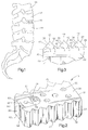
- One or several substantially rigid spinal implants 10 are placed between adjacent vertebrae 12 and 14 of a spinal column 16 in a side-by-side relationship to fuse together the adjacent vertebrae.
- the spinal implants 10 are made by injection molding a chopped carbon fiber reinforced polymer.
- the spinal implants 10 can be made of other suitable implantable materials such as stainless steel or titanium.
- the ultimate tensile strength of the material used to make the spinal implants 10 is higher than 10,000 psi so that the spinal implants will prevent relative movement between the adjacent vertebrae 12 and 14 and will support the compressive load of the spinal column.
- Each of the spinal implants 10 has parallel side surfaces 20 and 22.
- An upper surface 24 and a lower surface 26 for engaging the adjacent vertebrae 12 and 14 extend between the side surfaces 20 and 22.
- the upper and lower surfaces 24 and 26 adjacent a first end portion 30 of the spinal implant 10 are spaced apart by a first distance.
- the upper and lower surfaces 24 and 26 adjacent a second end portion 32 of the spinal implant 10 are spaced apart a second distance.
- the second distance is preferably greater than the first distance to give the spinal implant a wedge shape for use in portions of the spine with a lordotic curve.
- the spinal implant 10 is shown with a wedge shape for use in portions of the spine with a lordotic curve, the implant may have a wedge shape for use in portions of the spine with a kyphotic curve or may not be wedge shaped at all.
- the upper and lower surfaces 24 and 26 include a plurality of triangular-shaped teeth 36 that extend from the side surface 20 to the side surface 22 for engaging the vertebrae 12 and 14.
- Each tooth 36 (Fig. 3) includes a surface 40 facing toward the end portion 30.
- a surface 42 of the tooth 36 faces the end portion 32 of the spinal implant 10.
- the surfaces 40 and 42 of the tooth 36 intersect each other to form an edge 44.
- the surfaces 40 and 42 of adjacent teeth 36 intersect to form edges 46.
- the edges 46 are parallel to each other and lie in a plane 48.
- the surface 40 of the tooth 36 extends at an acute angle X to the plane 48.
- the surface 42 of the tooth 36 extends at an acute angle Y to the plane 48.
- the angles X and Y are equal and have a value of 45° so that surfaces 40 and 42 extend perpendicular to each other. Therefore, the teeth 36 are not preferential.
- the teeth 36 prevent the spinal implant 10 from moving toward the anterior portion of the spinal column 16 as much as they prevent the spinal implant from moving toward the posterior portion of the spinal column 16.
- the angles X and Y may have different values as desired by a surgeon.
- a plurality of openings 56 and 58 extend from the side surface 20 to the side surface 22 to provide for the flow of body fluids and bone growth from one side of the implant 10 to the other side of the implant.
- the openings 58 are located near the end portion 30 of the implant.
- the openings 56 and 58 extend perpendicular to the side surfaces 20 and 22.
- the openings 56 have diameters larger than the diameters of the openings 58.
- the sizes, shapes, and positions of the openings 56 and 58 may be varied as desired by a surgeon.
- the openings 56 and 58 are shown extending perpendicular to the side surfaces 20 and 22, the openings 56 and 58 may extend at an acute angle to the side surfaces 20 and 22. Also, it is contemplated that the spinal implant 10 may include recesses in the side surfaces 20 and 22 for receiving autograft or allograft bone, bone proteins, bone substitute, or the like instead of or along with the openings 56 and 58.
- the side surface 20 includes a recess 60 and the side surface 22 includes a recess 62.
- the openings 58 are located in the recesses 60 and 62.
- Each of the recesses 60 and 62 includes a planar bottom surface 64.
- the recesses 60 and 62 also include parallel side surfaces 66 and 68 extending perpendicular to the bottom surface 64 and from the end portion 30 of the spinal implant 10 toward the end portion 32.
- An arcuate side surface 70 extends between the parallel side surfaces 66 and 68.
- the recesses 60 and 62 may be located anywhere on the surfaces 20 and 22 depending on whether the implant 10 is going to be inserted posteriorly, anteriorly, or anterio-laterally.
- the recesses 60 and 62 in the side surfaces 20 and 22 are for receiving an instrument 80 (Fig. 4) that holds the spinal implant 10 to facilitate insertion of the spinal implant between the adjacent vertebrae 12 and 14 and rotation of the spinal implant once between the adjacent vertebrae.
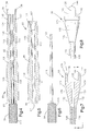
- One such instrument 80 includes an intermediate portion 82 (Fig. 5), a handle 84 (Fig. 6) and a clamp portion 86 (Figs. 7 and 8).
- the intermediate portion 82 (Fig. 5) is generally cylindrical and includes an opening 92 extending along the axis of the intermediate portion.
- the opening 92 includes a first cylindrical portion 94 extending from an end portion 96 of the intermediate portion 82 to a central portion 98.
- a second cylindrical portion 100 of the opening 92 extends from the first cylindrical portion 94 to a tapered portion 102 of the opening 92.
- the second cylindrical portion 100 of the opening 92 has a diameter larger than the diameter of the first cylindrical portion 94.
- the tapered portion 102 of the opening 92 tapers from a small diameter adjacent the portion 100 to a larger diameter adjacent an end portion 104 of the intermediate portion 82.
- the intermediate portion 82 includes a large outer diameter portion 108 that extends from the end portion 96 to the central portion 98.
- the portion 108 tapers from a large outer diameter to a small outer diameter portion 110 which extends from the portion 108 to the end portion 104.
- the outer surface of the portion 108 is preferably knurled to provide for easy gripping of the intermediate portion 82 by a surgeon.
- the end portion 96 has a diameter which is smaller than the portions 108 and 110.
- the handle 84 (Fig. 6) has a large diameter knurled portion 116.
- a small diameter shaft 118 extends from the knurled portion 116.
- the shaft 118 has a threaded end 120 for threadably engaging the clamp portion 86.
- the clamp portion 86 (Figs. 7 and 8) includes a stem 126 with an internally threaded opening 128 for receiving the threaded end 120 of the handle 84.
- a pair of clamp halves 130 are spaced apart and extend from the stem 126.
- the clamp halves 130 have outwardly tapering surfaces 132. The surfaces 132 taper from the stem 126 to a groove 134.
- the clamp halves 130 include extensions 136 which are received in the recesses 60 and 62 in the side surfaces 20 and 22 of the spinal implant 10.
- the extensions 136 include planar inner surfaces 138 (Fig. 7) for engaging the bottom planar surfaces 64 of the recesses 60 and 62.
- Parallel side surfaces 140 and 142 (Fig. 8) of the extensions 136 engage side surfaces 66 and 68 of the recesses 60 and 62 when the instrument 80 is used to hold the spinal implant 10.
- Arcuate side surface 144 for engaging the side surface 70 extends between the side surfaces 140 and 142.
- the shaft 118 of the handle 84 extends into the opening 92 in the intermediate portion 82 and threadably engages the stem 126 of the clamp portion 86 (Fig. 4).
- the clamp portion is drawn into the opening 92 in the intermediate portion 82.
- the tapered surfaces 132 of the clamp halves 130 engage the tapered portion 102 of the opening 92.
- the clamp halves 130 are forced toward each other by the tapered portion 102 of the opening 92 to clamp the spinal implant 10 between the extensions 136.
- the method of placing the spinal implants 10 between the adjacent vertebrae 12 and 14 to fuse together the adjacent vertebrae will now be described. Most of the spinal disc located between the vertebrae 12 and 14 is removed. The facing surfaces of the vertebrae 12 and 14 are cleaned with a disc shaver and rongeurs. Preferably, an annulus of the spinal disc is left between the vertebrae 12 and 14.
- the instrument 80 is used to hold a spinal implant 10.
- the spinal implant 10 is inserted posteriorly, anteriorly, or anterio-laterally as desired by a surgeon between the vertebrae 12 and 14 with the parallel side surfaces 20 and 22 facing the adjacent vertebrae 12 and 14.
- the implant 10 is shown being inserted posteriorly in Fig. 9.
- the spinal implant 10 is inserted so that the end portion 32 is near the anterior side of the spinal column 16 and the end portion 30 is near the posterior side of the spinal column.
- the spinal implant 10 is rotated 90° to the position shown in Fig. 10 so that the teeth 36 on the upper and lower surfaces 24 and 26 engage the vertebrae 12 and 14 and the side surfaces 20 and 22 extend from the vertebra 12 to the vertebra 14.
- the wedge shape of the spinal implant 10 alleviates the need to distract the posterior portion of the spine segment a large distance and then compress the posterior portion to achieve the required lordosis. The posterior portion only needs to be distracted to the desired interdiscal height.
- a second spinal implant 10 is inserted between the vertebrae 12 and 14 in a side-by-side relationship with the first spinal implant.
- the second spinal implant 10 is inserted in a similar manner as the first implant.
- the instrument 80 is used to hold the spinal implant 10.
- the spinal implant 10 is inserted with the parallel side surfaces 20 and 22 facing the vertebrae 12 and 14 (Fig. 11).
- the second spinal implant 10 is then rotated 90° to the position shown in Fig. 12 so that the teeth 36 of the upper and lower surfaces 24 and 26 engage the vertebrae 12 and 14.
- the remaining space between the spinal implants 10 and the adjacent vertebrae 12 and 14 is packed with autograft or allograft bone, bone proteins, bone substitute, or the like.
- An apparatus for maintaining the vertebrae 12 and 14 in a desired spatial relationship such as that disclosed in U.S. Patent No. 4,696,290 is attached to the spinal column 16 until the vertebrae 12 and 14 have completely fused together.
- the apparatus for maintaining the vertebrae 12 and 14 in the desired spatial relationship prevents the spinal implants 10 from moving out of position and the bone graft from falling out of the spaces between the spinal implants and the vertebrae 12 and 14.
- the spinal implant 10 has relatively small openings 56 and 58.
- the spinal implant has a relatively large opening extending between side surfaces. Since the embodiment of the invention illustrated in Figs. 13 and 14 is generally similar to the embodiment of the invention illustrated in Figs. 1-12, similar numerals will be utilized to designate similar components, the suffix letter "a" being associated with the numerals of Figs. 13 and 14 to avoid confusion.
- One or several substantially rigid spinal implants 10a are placed between adjacent vertebrae of a spinal column in a side-by-side relationship to fuse together the adjacent vertebrae.
- the spinal implants 10a are made by injection molding a chopped carbon fiber reinforced polymer.
- the spinal implants 10a can be made of other suitable implantable materials such as stainless steel or titanium.
- the ultimate tensile strength of the material used to make the spinal implants 10a is higher than 10,000 psi so that the spinal implants will prevent relative movement between the adjacent vertebrae and will support the compressive load of the spinal column.
- Each of the spinal implants 10a has parallel side surfaces 20a and 22a.
- An upper surface 24a and a lower surface 26a for engaging the adjacent vertebrae extend between the side surfaces 20a and 22a.
- the upper and lower surfaces 24a and 26a adjacent a first end portion 30a of the spinal implant 10a are spaced apart by a first distance.
- the upper and lower surfaces 24a and 26a adjacent a second end portion 32a of the spinal implant 10a are spaced apart a second distance.
- the second distance is preferably greater than the first distance to give the spinal implant a wedge shape for use in portions of the spine with a lordotic curve.
- the spinal implant 10a may have a different wedge shape or no wedge shape depending on the portion of the spine into which the implant is to be inserted.
- the upper and lower surfaces 24a and 26a include a plurality of triangular-shaped teeth 36a that extend from the side surface 20a to the side surface 22a for engaging the vertebrae.
- Each tooth 36a (Fig. 14) includes a surface 40a facing toward the end portion 30a.
- a surface 42a of each tooth 36a faces the end portion 32a of the spinal implant 10a.
- the surfaces 40a and 42a of the tooth 36a intersect each other to form an edge 44a.
- the surfaces 40a and 42a of adjacent teeth 36a intersect to form edges 46a.
- the edges 46a are parallel to each other and lie in a plane 48a.
- each tooth 36a extends at an acute angle C to the plane 48a.
- the surface 42a of each tooth 36a extends at an acute angle D to the plane 48a.
- the angles C and D are equal and have a value of 45° so that surfaces 40a and 42a extend perpendicular to each other. Therefore, the teeth 36a are not preferential.
- the values of angles C and D may be different.
- a relatively large opening 156 extends from the side surface 20a to the side surface 22a.
- the opening 156 is packed with autograft or allograft bone, bone proteins, bone substitute, or the like and provides for the flow of body fluids and bone growth from one side of the implant 10a to the other side of the implant.
- the opening 156 extends perpendicular to the side surfaces 20a and 22a and may extend at an angle to the side surfaces. The size, shape, and position of the opening 156 may be varied as desired by a surgeon.
- the side surface 20a includes a recess 60a and the side surface 22a includes a recess 62a.
- Each of the recesses 60a and 62a includes a planar bottom surface 64a, parallel side surfaces 66a and 68a extending perpendicular to the bottom surface 64a, and an arcuate side surface 70a extending between the parallel side surfaces 66a and 68a.
- the recesses 60a and 62a in the side surfaces 20a and 22a are for receiving the instrument 80 (Fig. 4) that holds the spinal implant 10a to facilitate insertion of the spinal implant between the adjacent vertebrae and rotation of the spinal implant once between the adjacent vertebrae.
- the instrument 80 is one such instrument that can be used.
- the method of placing the spinal implants 10a between adjacent vertebrae to fuse together the adjacent vertebrae is similar to the method of placing the spinal implants 10 between adjacent vertebrae as shown in Figs. 4-12 and therefore, will not be described in detail.
- Most of the spinal disc located between the vertebrae is removed.
- the facing surfaces of the vertebrae are cleaned with a disc shaver and rongeurs.
- an annulus of the spinal disc is left between the vertebrae.
- the opening 156 is packed with bone graft.
- the instrument 80 is used to hold a spinal implant 10a, as described in the embodiment of Figs. 1-12.
- the spinal implant 10a is inserted posteriorly, anteriorly, or anterio-laterally between the vertebrae with the parallel side surfaces 20a and 22a facing the adjacent vertebrae.
- the spinal implant 10a is inserted so that the end portion 32a is near the anterior side of the spinal column and the end portion 30a is near the posterior side of the spinal column.
- the spinal implant 10a is rotated 90° so that the teeth 36a on the upper and lower surfaces 24a and 26a engage the vertebrae and the side surfaces 20a and 22a extend between the adjacent vertebrae.
- a second spinal implant 10a is inserted between the vertebrae in a side-by-side relationship with the first spinal implant.
- the second spinal implant 10a is inserted in a similar manner as the first implant.
- the opening 156 is packed with bone graft.
- the instrument 80 is used to hold the spinal implant 10a.
- the spinal implant 10a is inserted with the parallel side surfaces 20a and 22a facing the vertebrae.
- the second spinal implant 10a is then rotated 90° so that the teeth 36a of the upper and lower surfaces 24a and 26a engage the vertebrae.
- the remaining space between the spinal implants 10a and the adjacent vertebrae is packed with autograft or allograft bone, bone proteins, bone substitute, or the like.
- a suitable apparatus for maintaining the vertebrae in a desired spatial relationship is attached to the spinal column until the vertebrae have completely fused together.
- the spinal implants have openings extending between side surfaces only.
- the spinal implant has an opening extending between side surfaces and an opening extending between upper and lower surfaces that engage adjacent vertebrae. Since the embodiment of the invention illustrated in Figs. 15 and 16 is generally similar to the embodiments of the invention illustrated in Figs. 1-14, similar numerals will be utilized to designate similar components, the suffix letter "b" being associated with the numerals of Figs. 15 and 16 to avoid confusion.
- One or several substantially rigid spinal implants 10b are placed between adjacent vertebrae of a spinal column in a side-by-side relationship to fuse together the adjacent vertebrae.
- the spinal implants 10b are made by injection molding a chopped carbon fiber reinforced polymer.
- the spinal implants 10b can be made of other suitable implantable materials such as stainless steel or titanium.
- the ultimate tensile strength of the material used to make the spinal implants 10b is higher than 10,000 psi so that the spinal implants will prevent relative movement between the adjacent vertebrae and will support the compressive load of the spinal column.
- Each of the spinal implants 10b has parallel side surfaces 20b and 22b.
- An upper surface 24b and a lower surface 26b for engaging the adjacent vertebrae extend between the side surfaces 20b and 22b.
- the upper and lower surfaces 24b and 26b adjacent a first end portion 30b of the spinal implant 10b are spaced apart by a first distance.
- the upper and lower surfaces 24b and 26b adjacent a second end portion 32b of the spinal implant 10b are spaced apart a second distance.
- the second distance is preferably greater than the first distance to give the spinal implant a wedge shape for use in portions of the spine with a lordotic curve.
- the spinal implant 10b may have a different wedge shape or no wedge shape depending on the portion of the spine into which the implant is to be inserted.
- the upper and lower surfaces 24b and 26b include a plurality of triangular-shaped teeth 36b that extend from the side surface 20b to the side surface 22b for engaging the vertebrae.
- Each tooth 36b (Fig. 16) includes a surface 40b facing toward the end portion 30b.
- a surface 42b of each tooth 36b faces the end portion 32b of the spinal implant 10b.
- the surfaces 40b and 42b of each tooth 36b intersect each other to form an edge 44b.
- the surfaces 40b and 42b of adjacent teeth 36b intersect to form edges 46b.
- the edges 46b are parallel to each other and lie in a plane 48b.
- each tooth 36b extends at an acute angle F to the plane 48b.
- the surface 42b of each tooth 36b extends at an acute angle G to the plane 48b.
- the angles F and G are equal and have a value of 45° so that surfaces 40b and 42b extend perpendicular to each other. Therefore, the teeth 36b are not preferential.
- the values of angles F and G may be different.
- a relatively large circular opening 156b extends from the side surface 20b to the side surface 22b.
- a relatively large rectangular opening 160 extends from the upper surface 24b to the lower surface 26b and intersects the opening 156b.
- the openings 156b and 160 are packed with autograft or allograft bone, bone proteins, bone substitute, or the like and provide for the flow of body fluids and bone growth through the implant 10b.
- the sizes, shapes, and positions of the openings 156b and 160 may be varied as desired by a surgeon.
- the side surface 20b includes a recess 60b and the side surface 22b includes a recess 62b.
- Each of the recesses 60b and 62b includes a planar bottom surface 64b, parallel side surfaces 66b and 68b, and an arcuate side surface 70b extending between the parallel side surfaces 66b and 68b.
- the recesses 60b and 62b in the side surfaces 20b and 22b are for receiving the instrument 80 (Fig. 4) that holds the spinal implant 10b to facilitate insertion of the spinal implant between adjacent vertebrae and rotation of the spinal implant once between the adjacent vertebrae.
- the instrument 80 is one such instrument that can be used.
- the method of placing the spinal implants 10b between adjacent vertebrae to fuse together the adjacent vertebrae is similar to the method of placing the spinal implants 10 between adjacent vertebrae as shown in Figs. 4-12 and will not be described in detail.
- Most of the spinal disc located between the vertebrae is removed.
- the facing surfaces of the vertebrae are cleaned with a disc shaver and rongeurs.
- an annulus of the spinal disc is left between the vertebrae.
- the openings 156b and 160 are packed with bone graft.
- the instrument 80 is used to hold a spinal implant 10b, as described in the embodiment of Figs. 1-12.
- the spinal implant 10b is inserted posteriorly, anteriorly, or anterio-laterally between the vertebrae with the parallel side surfaces 20b and 22b facing the adjacent vertebrae.
- the spinal implant 10b is inserted so that the end portion 32b is near the anterior side of the spinal column and the end portion 30b is near the posterior side of the spinal column.
- the spinal implant 10b is rotated 90° so that the teeth 36b on the upper and lower surfaces 24b and 26b engage the vertebrae and the side surfaces 20b and 22b extend between the vertebrae.
- a second spinal implant 10b is inserted between the vertebrae in a side-by-side relationship with the first spinal implant.
- the second spinal implant 10b is inserted in a similar manner as the first implant.
- the openings 156b and 160 are packed with bone graft.
- the instrument 80 is used to hold the spinal implant 10b.
- the spinal implant 10b is inserted with the parallel side surfaces 20b and 22b facing the vertebrae.
- the second spinal implant 10b is then rotated 90° so that the teeth 36b of the upper and lower surfaces 24b and 26b engage the vertebrae.
- the remaining space between the spinal implants 10b and the adjacent vertebrae is packed with autograft or allograft bone, bone proteins, bone substitute, or the like.
- An apparatus for maintaining the vertebrae in a desired spatial relationship is attached to the spinal column until the vertebrae have completely fused together.
Abstract
Description
- The present invention relates to a spinal implant, and to a method of using the spinal implant to fuse together adjacent vertebrae of a spinal column.
- A known spinal implant has a rectangular shape and a tapered end. The spinal implant includes nubs to grip adjacent vertebrae. The nubs have inclined faces that accommodate forward sliding movement of the spinal implant into channels cut in the adjacent vertebrae. This known spinal implant is described in U.S. Patent No. 4,834,757. By cutting channels into the vertebrae for receiving the spinal implant, nerve roots are put at risk.
- The present invention provides a new and improved spinal implant and method of using the spinal implant to fuse together adjacent vertebrae of a spinal column. The spinal implant of the present invention includes first and second side surfaces extending substantially parallel to each other. Upper and lower surface means for engaging the adjacent vertebrae extend between the first and second side surfaces and extend from a first end portion to a second end portion of the spinal implant. The spinal implant includes means engagable with a tool for rotating the spinal implant when the implant is located between the adjacent vertebrae.
- The method of using the spinal implant to fuse together the adjacent vertebrae of a spinal column includes removing at least a portion of the spinal disc between the adjacent vertebrae. The spinal implant is inserted between the adjacent vertebrae with the first and second substantially parallel side surfaces facing the adjacent vertebrae. The spinal implant is rotated into a position in which the parallel side surfaces extend from one of the adjacent vertebrae to the other of the adjacent vertebrae and the upper and lower surface means engage the adjacent vertebrae. There are no channels cut in the adjacent vertebrae. Thus, the operation takes less time and lessens the risks to the patient.
- The foregoing and other features of the present invention will become more apparent to one skilled in the art upon reading the following description of the present invention with reference to the accompanying drawings, wherein:
- Fig. 1 is an elevation view of a human spinal column having a first embodiment of a spinal implant in accordance with the present invention placed therein;
- Fig. 2 is a perspective view of the spinal implant of Fig. 1;
- Fig. 3 is an enlarged plan view looking at a portion of the spinal implant of Fig. 2 from the side;
- Fig. 4 is a sectional view of an instrument for holding the spinal implant of Fig. 2 to facilitate inserting the spinal implant between adjacent vertebrae and rotating the spinal implant;
- Fig. 5 is a sectional view of an intermediate portion of the instrument of Fig. 4;
- Fig. 6 is a plan view of a handle of the instrument of Fig. 4;
- Fig. 7 is a sectional view of a clamp portion of the instrument of Fig. 4;
- Fig. 8 is a plan view of the clamp portion of Fig. 7 taken along the line 8-8 of Fig. 7;
- Figs. 9-12 are views showing a method of inserting spinal implants in a side-by-side relationship between adjacent vertebrae;
- Fig. 13 is a perspective view of a second embodiment of a spinal implant of the present invention;
- Fig. 14 is an enlarged plan view looking at a portion of the spinal implant of Fig. 13 from the side;
- Fig. 15 is a perspective view of a third embodiment of a spinal implant of the present invention; and
- Fig. 16 is an enlarged plan view looking at a portion of the spinal implant of Fig. 15 from the side.
- A first embodiment of a spinal implant of the present invention and method of inserting the spinal implant between adjacent vertebrae are shown in Figs. 1-12.
- One or several substantially rigid spinal implants 10 (one of which is shown in Fig. 1) are placed between
adjacent vertebrae spinal column 16 in a side-by-side relationship to fuse together the adjacent vertebrae. Preferably, thespinal implants 10 are made by injection molding a chopped carbon fiber reinforced polymer. However, thespinal implants 10 can be made of other suitable implantable materials such as stainless steel or titanium. Also, preferably, the ultimate tensile strength of the material used to make thespinal implants 10 is higher than 10,000 psi so that the spinal implants will prevent relative movement between theadjacent vertebrae - Each of the spinal implants 10 (Fig. 2) has
parallel side surfaces upper surface 24 and alower surface 26 for engaging theadjacent vertebrae side surfaces lower surfaces first end portion 30 of thespinal implant 10 are spaced apart by a first distance. The upper andlower surfaces second end portion 32 of thespinal implant 10 are spaced apart a second distance. The second distance is preferably greater than the first distance to give the spinal implant a wedge shape for use in portions of the spine with a lordotic curve. Although thespinal implant 10 is shown with a wedge shape for use in portions of the spine with a lordotic curve, the implant may have a wedge shape for use in portions of the spine with a kyphotic curve or may not be wedge shaped at all. - The upper and
lower surfaces shaped teeth 36 that extend from theside surface 20 to theside surface 22 for engaging thevertebrae surface 40 facing toward theend portion 30. Asurface 42 of thetooth 36 faces theend portion 32 of thespinal implant 10. Thesurfaces tooth 36 intersect each other to form anedge 44. Thesurfaces adjacent teeth 36 intersect toform edges 46. Theedges 46 are parallel to each other and lie in aplane 48. - The
surface 40 of thetooth 36 extends at an acute angle X to theplane 48. Thesurface 42 of thetooth 36 extends at an acute angle Y to theplane 48. Preferably, the angles X and Y are equal and have a value of 45° so thatsurfaces teeth 36 are not preferential. Theteeth 36 prevent thespinal implant 10 from moving toward the anterior portion of thespinal column 16 as much as they prevent the spinal implant from moving toward the posterior portion of thespinal column 16. However, the angles X and Y may have different values as desired by a surgeon. - A plurality of
openings side surface 20 to theside surface 22 to provide for the flow of body fluids and bone growth from one side of theimplant 10 to the other side of the implant. Theopenings 58 are located near theend portion 30 of the implant. Theopenings side surfaces openings 56 and twoopenings 58 extending between thesides openings 56 have diameters larger than the diameters of theopenings 58. The sizes, shapes, and positions of theopenings openings side surfaces openings side surfaces spinal implant 10 may include recesses in theside surfaces openings - The
side surface 20 includes arecess 60 and theside surface 22 includes arecess 62. Theopenings 58 are located in therecesses recesses planar bottom surface 64. Therecesses bottom surface 64 and from theend portion 30 of thespinal implant 10 toward theend portion 32. Anarcuate side surface 70 extends between the parallel side surfaces 66 and 68. Therecesses surfaces implant 10 is going to be inserted posteriorly, anteriorly, or anterio-laterally. Therecesses spinal implant 10 to facilitate insertion of the spinal implant between theadjacent vertebrae - Any instrument that firmly holds the implant and permits the implant to be rotated into position can be used. One such instrument 80 (Fig. 4) includes an intermediate portion 82 (Fig. 5), a handle 84 (Fig. 6) and a clamp portion 86 (Figs. 7 and 8).
- The intermediate portion 82 (Fig. 5) is generally cylindrical and includes an
opening 92 extending along the axis of the intermediate portion. Theopening 92 includes a firstcylindrical portion 94 extending from anend portion 96 of theintermediate portion 82 to acentral portion 98. A secondcylindrical portion 100 of theopening 92 extends from the firstcylindrical portion 94 to a taperedportion 102 of theopening 92. The secondcylindrical portion 100 of theopening 92 has a diameter larger than the diameter of the firstcylindrical portion 94. The taperedportion 102 of theopening 92 tapers from a small diameter adjacent theportion 100 to a larger diameter adjacent anend portion 104 of theintermediate portion 82. - The
intermediate portion 82 includes a largeouter diameter portion 108 that extends from theend portion 96 to thecentral portion 98. Theportion 108 tapers from a large outer diameter to a smallouter diameter portion 110 which extends from theportion 108 to theend portion 104. The outer surface of theportion 108 is preferably knurled to provide for easy gripping of theintermediate portion 82 by a surgeon. Theend portion 96 has a diameter which is smaller than theportions - The handle 84 (Fig. 6) has a large
diameter knurled portion 116. Asmall diameter shaft 118 extends from theknurled portion 116. Theshaft 118 has a threadedend 120 for threadably engaging theclamp portion 86. - The clamp portion 86 (Figs. 7 and 8) includes a
stem 126 with an internally threadedopening 128 for receiving the threadedend 120 of thehandle 84. A pair ofclamp halves 130 are spaced apart and extend from thestem 126. The clamp halves 130 have outwardly taperingsurfaces 132. Thesurfaces 132 taper from thestem 126 to agroove 134. - The clamp halves 130 include
extensions 136 which are received in therecesses spinal implant 10. Theextensions 136 include planar inner surfaces 138 (Fig. 7) for engaging the bottomplanar surfaces 64 of therecesses extensions 136 engageside surfaces recesses instrument 80 is used to hold thespinal implant 10.Arcuate side surface 144 for engaging theside surface 70 extends between the side surfaces 140 and 142. - The
shaft 118 of thehandle 84 extends into theopening 92 in theintermediate portion 82 and threadably engages thestem 126 of the clamp portion 86 (Fig. 4). As thehandle 84 is threaded into theopening 128 of theclamp portion 86, the clamp portion is drawn into theopening 92 in theintermediate portion 82. The tapered surfaces 132 of the clamp halves 130 engage the taperedportion 102 of theopening 92. As theclamp portion 86 is drawn into theopening 92, the clamp halves 130 are forced toward each other by the taperedportion 102 of theopening 92 to clamp thespinal implant 10 between theextensions 136. - The method of placing the
spinal implants 10 between theadjacent vertebrae vertebrae vertebrae vertebrae - The
instrument 80 is used to hold aspinal implant 10. Thespinal implant 10 is inserted posteriorly, anteriorly, or anterio-laterally as desired by a surgeon between thevertebrae adjacent vertebrae implant 10 is shown being inserted posteriorly in Fig. 9. Thespinal implant 10 is inserted so that theend portion 32 is near the anterior side of thespinal column 16 and theend portion 30 is near the posterior side of the spinal column. Thespinal implant 10 is rotated 90° to the position shown in Fig. 10 so that theteeth 36 on the upper andlower surfaces vertebrae vertebra 12 to thevertebra 14. The wedge shape of thespinal implant 10 alleviates the need to distract the posterior portion of the spine segment a large distance and then compress the posterior portion to achieve the required lordosis. The posterior portion only needs to be distracted to the desired interdiscal height. - A second
spinal implant 10 is inserted between thevertebrae spinal implant 10 is inserted in a similar manner as the first implant. Theinstrument 80 is used to hold thespinal implant 10. Thespinal implant 10 is inserted with the parallel side surfaces 20 and 22 facing thevertebrae 12 and 14 (Fig. 11). The secondspinal implant 10 is then rotated 90° to the position shown in Fig. 12 so that theteeth 36 of the upper andlower surfaces vertebrae - The remaining space between the
spinal implants 10 and theadjacent vertebrae vertebrae spinal column 16 until thevertebrae vertebrae spinal implants 10 from moving out of position and the bone graft from falling out of the spaces between the spinal implants and thevertebrae - In the embodiment of the invention illustrated in Figs. 1-12, the
spinal implant 10 has relativelysmall openings - One or several substantially rigid
spinal implants 10a (one of which is shown in Fig. 13) are placed between adjacent vertebrae of a spinal column in a side-by-side relationship to fuse together the adjacent vertebrae. Preferably, thespinal implants 10a are made by injection molding a chopped carbon fiber reinforced polymer. However, thespinal implants 10a can be made of other suitable implantable materials such as stainless steel or titanium. Also, preferably, the ultimate tensile strength of the material used to make thespinal implants 10a is higher than 10,000 psi so that the spinal implants will prevent relative movement between the adjacent vertebrae and will support the compressive load of the spinal column. - Each of the
spinal implants 10a (Fig. 13) hasparallel side surfaces 20a and 22a. Anupper surface 24a and a lower surface 26a for engaging the adjacent vertebrae extend between the side surfaces 20a and 22a. The upper andlower surfaces 24a and 26a adjacent afirst end portion 30a of thespinal implant 10a are spaced apart by a first distance. The upper andlower surfaces 24a and 26a adjacent asecond end portion 32a of thespinal implant 10a are spaced apart a second distance. The second distance is preferably greater than the first distance to give the spinal implant a wedge shape for use in portions of the spine with a lordotic curve. Thespinal implant 10a may have a different wedge shape or no wedge shape depending on the portion of the spine into which the implant is to be inserted. - The upper and
lower surfaces 24a and 26a include a plurality of triangular-shapedteeth 36a that extend from the side surface 20a to theside surface 22a for engaging the vertebrae. Eachtooth 36a (Fig. 14) includes asurface 40a facing toward theend portion 30a. Asurface 42a of eachtooth 36a faces theend portion 32a of thespinal implant 10a. Thesurfaces tooth 36a intersect each other to form anedge 44a. Thesurfaces adjacent teeth 36a intersect to formedges 46a. Theedges 46a are parallel to each other and lie in aplane 48a. - The
surface 40a of eachtooth 36a extends at an acute angle C to theplane 48a. Thesurface 42a of eachtooth 36a extends at an acute angle D to theplane 48a. Preferably, the angles C and D are equal and have a value of 45° so thatsurfaces teeth 36a are not preferential. However, the values of angles C and D may be different. - A relatively
large opening 156 extends from the side surface 20a to theside surface 22a. Theopening 156 is packed with autograft or allograft bone, bone proteins, bone substitute, or the like and provides for the flow of body fluids and bone growth from one side of theimplant 10a to the other side of the implant. Theopening 156 extends perpendicular to the side surfaces 20a and 22a and may extend at an angle to the side surfaces. The size, shape, and position of theopening 156 may be varied as desired by a surgeon. - The side surface 20a includes a
recess 60a and theside surface 22a includes a recess 62a. Each of therecesses 60a and 62a includes a planarbottom surface 64a,parallel side surfaces 66a and 68a extending perpendicular to thebottom surface 64a, and anarcuate side surface 70a extending between theparallel side surfaces 66a and 68a. Therecesses 60a and 62a in the side surfaces 20a and 22a are for receiving the instrument 80 (Fig. 4) that holds thespinal implant 10a to facilitate insertion of the spinal implant between the adjacent vertebrae and rotation of the spinal implant once between the adjacent vertebrae. - Any instrument that firmly holds the
implant 10a and permits the implant to be rotated into position can be used. Theinstrument 80 is one such instrument that can be used. - The method of placing the
spinal implants 10a between adjacent vertebrae to fuse together the adjacent vertebrae is similar to the method of placing thespinal implants 10 between adjacent vertebrae as shown in Figs. 4-12 and therefore, will not be described in detail. Most of the spinal disc located between the vertebrae is removed. The facing surfaces of the vertebrae are cleaned with a disc shaver and rongeurs. Preferably, an annulus of the spinal disc is left between the vertebrae. - The
opening 156 is packed with bone graft. Theinstrument 80 is used to hold aspinal implant 10a, as described in the embodiment of Figs. 1-12. Thespinal implant 10a is inserted posteriorly, anteriorly, or anterio-laterally between the vertebrae with theparallel side surfaces 20a and 22a facing the adjacent vertebrae. Thespinal implant 10a is inserted so that theend portion 32a is near the anterior side of the spinal column and theend portion 30a is near the posterior side of the spinal column. Thespinal implant 10a is rotated 90° so that theteeth 36a on the upper andlower surfaces 24a and 26a engage the vertebrae and the side surfaces 20a and 22a extend between the adjacent vertebrae. - A second
spinal implant 10a is inserted between the vertebrae in a side-by-side relationship with the first spinal implant. The secondspinal implant 10a is inserted in a similar manner as the first implant. Theopening 156 is packed with bone graft. Theinstrument 80 is used to hold thespinal implant 10a. Thespinal implant 10a is inserted with theparallel side surfaces 20a and 22a facing the vertebrae. The secondspinal implant 10a is then rotated 90° so that theteeth 36a of the upper andlower surfaces 24a and 26a engage the vertebrae. - The remaining space between the
spinal implants 10a and the adjacent vertebrae is packed with autograft or allograft bone, bone proteins, bone substitute, or the like. A suitable apparatus for maintaining the vertebrae in a desired spatial relationship is attached to the spinal column until the vertebrae have completely fused together. - In the embodiments of the invention illustrated in Figs. 1-14, the spinal implants have openings extending between side surfaces only. In the embodiment of the invention illustrated in Figs. 15 and 16, the spinal implant has an opening extending between side surfaces and an opening extending between upper and lower surfaces that engage adjacent vertebrae. Since the embodiment of the invention illustrated in Figs. 15 and 16 is generally similar to the embodiments of the invention illustrated in Figs. 1-14, similar numerals will be utilized to designate similar components, the suffix letter "b" being associated with the numerals of Figs. 15 and 16 to avoid confusion.
- One or several substantially rigid
spinal implants 10b (one of which is shown in Fig. 15) are placed between adjacent vertebrae of a spinal column in a side-by-side relationship to fuse together the adjacent vertebrae. Preferably, thespinal implants 10b are made by injection molding a chopped carbon fiber reinforced polymer. However, thespinal implants 10b can be made of other suitable implantable materials such as stainless steel or titanium. Also, preferably, the ultimate tensile strength of the material used to make thespinal implants 10b is higher than 10,000 psi so that the spinal implants will prevent relative movement between the adjacent vertebrae and will support the compressive load of the spinal column. - Each of the
spinal implants 10b (Fig. 15) has parallel side surfaces 20b and 22b. Anupper surface 24b and a lower surface 26b for engaging the adjacent vertebrae extend between the side surfaces 20b and 22b. The upper andlower surfaces 24b and 26b adjacent afirst end portion 30b of thespinal implant 10b are spaced apart by a first distance. The upper andlower surfaces 24b and 26b adjacent asecond end portion 32b of thespinal implant 10b are spaced apart a second distance. The second distance is preferably greater than the first distance to give the spinal implant a wedge shape for use in portions of the spine with a lordotic curve. Thespinal implant 10b may have a different wedge shape or no wedge shape depending on the portion of the spine into which the implant is to be inserted. - The upper and
lower surfaces 24b and 26b include a plurality of triangular-shapedteeth 36b that extend from theside surface 20b to theside surface 22b for engaging the vertebrae. Eachtooth 36b (Fig. 16) includes asurface 40b facing toward theend portion 30b. Asurface 42b of eachtooth 36b faces theend portion 32b of thespinal implant 10b. Thesurfaces tooth 36b intersect each other to form anedge 44b. Thesurfaces adjacent teeth 36b intersect to formedges 46b. Theedges 46b are parallel to each other and lie in aplane 48b. - The
surface 40b of eachtooth 36b extends at an acute angle F to theplane 48b. Thesurface 42b of eachtooth 36b extends at an acute angle G to theplane 48b. Preferably, the angles F and G are equal and have a value of 45° so thatsurfaces teeth 36b are not preferential. However, the values of angles F and G may be different. - A relatively large
circular opening 156b extends from theside surface 20b to theside surface 22b. A relatively largerectangular opening 160 extends from theupper surface 24b to the lower surface 26b and intersects theopening 156b. Theopenings implant 10b. The sizes, shapes, and positions of theopenings - The
side surface 20b includes arecess 60b and theside surface 22b includes arecess 62b. Each of therecesses bottom surface 64b, parallel side surfaces 66b and 68b, and anarcuate side surface 70b extending between the parallel side surfaces 66b and 68b. Therecesses spinal implant 10b to facilitate insertion of the spinal implant between adjacent vertebrae and rotation of the spinal implant once between the adjacent vertebrae. - Any instrument that firmly holds the
implant 10b and permits the implant to be rotated into position can be used. Theinstrument 80 is one such instrument that can be used. - The method of placing the
spinal implants 10b between adjacent vertebrae to fuse together the adjacent vertebrae is similar to the method of placing thespinal implants 10 between adjacent vertebrae as shown in Figs. 4-12 and will not be described in detail. Most of the spinal disc located between the vertebrae is removed. The facing surfaces of the vertebrae are cleaned with a disc shaver and rongeurs. Preferably, an annulus of the spinal disc is left between the vertebrae. - The
openings instrument 80 is used to hold aspinal implant 10b, as described in the embodiment of Figs. 1-12. Thespinal implant 10b is inserted posteriorly, anteriorly, or anterio-laterally between the vertebrae with the parallel side surfaces 20b and 22b facing the adjacent vertebrae. Thespinal implant 10b is inserted so that theend portion 32b is near the anterior side of the spinal column and theend portion 30b is near the posterior side of the spinal column. Thespinal implant 10b is rotated 90° so that theteeth 36b on the upper andlower surfaces 24b and 26b engage the vertebrae and the side surfaces 20b and 22b extend between the vertebrae. - A second
spinal implant 10b is inserted between the vertebrae in a side-by-side relationship with the first spinal implant. The secondspinal implant 10b is inserted in a similar manner as the first implant. Theopenings instrument 80 is used to hold thespinal implant 10b. Thespinal implant 10b is inserted with the parallel side surfaces 20b and 22b facing the vertebrae. The secondspinal implant 10b is then rotated 90° so that theteeth 36b of the upper andlower surfaces 24b and 26b engage the vertebrae. - The remaining space between the
spinal implants 10b and the adjacent vertebrae is packed with autograft or allograft bone, bone proteins, bone substitute, or the like. An apparatus for maintaining the vertebrae in a desired spatial relationship is attached to the spinal column until the vertebrae have completely fused together. - From the above description of the invention, those skilled in the art will perceive improvements, changes and modifications. Such improvements, changes and modifications within the skill of the art are intended to be covered by the appended claims.
Claims (23)
- A spinal implant for use in fusing together adjacent vertebrae of a spinal column comprising:
first and second side surfaces extending substantially parallel to each other;
upper and lower surface means for engaging the adjacent vertebrae extending between said first and second side surfaces;
first and second end portions; and
means for engaging a tool for rotating said spinal implant from a position in which said first and second side surfaces face the adjacent vertebrae to a position in which said upper and lower surface means engage the adjacent vertebrae. - A spinal implant as set forth in claim 1 wherein said upper and lower surface means extend from said first end portion to said second end portion, said upper and lower surface means adjacent said first end portion being spaced apart by a first distance and said upper and lower surface means adjacent said second end portion being spaced apart by a second distance greater than the first distance.
- A spinal implant as set forth in claim 1 further including at least one opening extending through said spinal implant.
- A spinal implant as set forth in claim 3 wherein said opening extends from said upper surface means to said lower surface means.
- A spinal implant as set forth in claim 3 wherein said opening extends from said first side surface to said second side surface.
- A spinal implant as set forth in claim 5 further including a plurality of openings extending from said first side surface to said second side surface.
- A spinal implant as set forth in claim 6 wherein said openings extend substantially perpendicular to said first and second side surfaces.
- A spinal implant as set forth in claim 5 further including an opening extending from said upper surface means to said lower surface means.
- A spinal implant as set forth in claim 8 wherein said opening extending from said upper surface means to said lower surface means intersects said opening extending from said first side surface to said second side surface.
- A spinal implant as set forth in claim 1 wherein said upper and lower surface means include teeth for engaging the adjacent vertebrae.
- A spinal implant as set forth in claim 10 wherein said teeth on said upper and lower surface means are triangular shaped.
- A spinal implant as set forth in claim 11 wherein each of said teeth includes a first surface facing toward said first end portion and a second surface extending from said first surface of said tooth and facing said second end portion, said first and second surfaces of said tooth intersecting each other to form an edge, said first surface extending at an acute angle to a plane containing an edge of said first surface opposite from said edge defined by the intersection of said first and second surfaces and containing an edge of said second surface opposite from said edge defined by the intersection of said first and second surfaces, said second surface extending at an acute angle to the plane equal to the acute angle that said first surface extends from said plane.
- A spinal implant as set forth in claim 12 wherein said first surface extends perpendicular to said second surface.
- A spinal implant as set forth in claim 1 wherein said means for engaging a tool for rotating said spinal implant comprises recesses in said first and second side surfaces for receiving the tool for grasping and rotating said spinal implant.
- A spinal implant as set forth in claim 2 wherein said means for engaging a tool for rotating said spinal implant comprises recesses located adjacent said first end portion of said spinal implant.
- A method of fusing together adjacent vertebrae of a spinal column comprising the steps of:
removing at least a portion of the disc between the adjacent vertebrae;
providing a spinal implant with first and second side surfaces substantially parallel to each other and upper and lower surface means extending between the first and second side surfaces;
inserting the spinal implant between the adjacent vertebrae with the first and second substantially parallel side surfaces of the spinal implant facing the adjacent vertebrae; and
rotating the spinal implant into a position in which the parallel side surfaces of the spinal implant extend from one of the adjacent vertebrae to the other adjacent vertebrae and the upper and lower surface means engage the adjacent vertebrae. - A method as set forth in claim 16 further including providing the spinal implant with first and second end portions wherein the upper and lower surface means are spaced apart by a first distance adjacent the first end portion and are spaced apart by a second distance greater than the first distance adjacent the second end portion.
- A method as set forth in claim 17 wherein said step of inserting the spinal implant includes inserting the spinal implant from the posterior side of the spinal column into a position in which the first end portion of the spinal implant is located adjacent the posterior side of the spinal column and the second end portion of the spinal implant is located adjacent the anterior side of the spinal column.
- A method as set forth in claim 16 wherein said step of inserting the spinal implant includes inserting two spinal implants in a side-by-side relationship.
- A method as set forth in claim 16 further including the step of packing bone graft around the spinal implant after said step of rotating the spinal implant.
- A method as set forth in claim 16 further including the step of attaching an apparatus to the spinal column for maintaining a desired spatial relationship of the adjacent vertebrae.
- A method as set forth in claim 16 wherein said step of removing at least a portion of the spinal disc includes leaving an annulus of the disc around the peripheries of the adjacent vertebrae.
- A method as set forth in claim 16 further including the step of packing bone graft material into an opening extending through the spinal implant.
Applications Claiming Priority (4)
| Application Number | Priority Date | Filing Date | Title |
|---|---|---|---|
| US08/130,288 US5443514A (en) | 1993-10-01 | 1993-10-01 | Method for using spinal implants |
| US130288 | 1993-10-01 | ||
| US28709694A | 1994-08-08 | 1994-08-08 | |
| US287096 | 1994-08-08 |
Publications (2)
| Publication Number | Publication Date |
|---|---|
| EP0646366A1 true EP0646366A1 (en) | 1995-04-05 |
| EP0646366B1 EP0646366B1 (en) | 1997-12-17 |
Family
ID=26828330
Family Applications (1)
| Application Number | Title | Priority Date | Filing Date |
|---|---|---|---|
| EP94115543A Expired - Lifetime EP0646366B1 (en) | 1993-10-01 | 1994-10-04 | Spinal implant |
Country Status (9)
| Country | Link |
|---|---|
| US (1) | US5716415A (en) |
| EP (1) | EP0646366B1 (en) |
| JP (1) | JP2855079B2 (en) |
| KR (1) | KR0153410B1 (en) |
| CN (1) | CN1156255C (en) |
| AT (1) | ATE161164T1 (en) |
| CA (1) | CA2133276C (en) |
| DE (1) | DE69407376T2 (en) |
| ES (1) | ES2111823T3 (en) |
Cited By (34)
| Publication number | Priority date | Publication date | Assignee | Title |
|---|---|---|---|---|
| FR2724312A1 (en) * | 1995-04-21 | 1996-03-15 | Alby Albert | Inter-somatic dorsal-lumber spacer |
| EP0734703A2 (en) * | 1995-03-27 | 1996-10-02 | Danek Medical, Inc. | Interbody fusion device and method for restoration of normal spinal anatomy |
| WO1997006753A2 (en) * | 1995-08-11 | 1997-02-27 | Bernhard Zientek | Intervertebral implant, process for widening and instruments for implanting an intervertebral implant |
| WO1997015248A1 (en) * | 1995-10-20 | 1997-05-01 | Synthes Ag Chur | Inter-vertebral implant |
| WO1997030666A2 (en) * | 1996-02-22 | 1997-08-28 | Sdgi Holdings, Inc. | Methods and instruments for interbody fusion |
| ES2107377A1 (en) * | 1995-07-31 | 1997-11-16 | Univ De A Coruna | Intervertebral disc prosthesis |
| EP0840580A1 (en) * | 1995-06-07 | 1998-05-13 | MICHELSON, Gary Karlin | Lordotic interbody spinal fusion implants |
| WO1998035636A1 (en) * | 1995-06-07 | 1998-08-20 | Sdgi Holdings, Inc. | Anterior spinal instrumentation and method for implantation and revision |
| WO1998038924A3 (en) * | 1997-03-06 | 1998-12-10 | Sulzer Spine Tech Ltd | Lordotic spinal implant |
| FR2767676A1 (en) * | 1997-08-26 | 1999-03-05 | Materiel Orthopedique En Abreg | Spinal cage implant for promoting fusion of two or more vertebrae |
| WO1999009913A3 (en) * | 1997-08-26 | 1999-05-06 | Soc D Fabrication Materiel Ort | Spinal implant and cutting tool preparation accesory for mounting the implant |
| WO1999052453A3 (en) * | 1998-04-09 | 2000-01-13 | Sdgi Holdings Inc | Method and instrumentation for vertebral interbody fusion |
| WO2000007527A1 (en) * | 1998-08-03 | 2000-02-17 | Synthes Ag Chur | Intervertebral allograft spacer |
| FR2784891A1 (en) * | 1998-10-22 | 2000-04-28 | Hassan Razian | Surgical cage for spinal support has spacer disc with rotatable foot at set spacing |
| US6245072B1 (en) | 1995-03-27 | 2001-06-12 | Sdgi Holdings, Inc. | Methods and instruments for interbody fusion |
| US6428541B1 (en) | 1998-04-09 | 2002-08-06 | Sdgi Holdings, Inc. | Method and instrumentation for vertebral interbody fusion |
| WO2002062235A2 (en) * | 2001-01-08 | 2002-08-15 | Sdgi Holdings, Inc. | Methods and instrumentation for vertebral interbody fusion |
| WO2002076350A1 (en) * | 2001-03-22 | 2002-10-03 | Howmedica Osteonics Corp | Apparatus for fusing adjacent bone structures |
| WO2003037228A3 (en) * | 2001-10-30 | 2003-07-31 | Osteotech Inc | Bone implant and insertion tools |
| US6613091B1 (en) | 1995-03-27 | 2003-09-02 | Sdgi Holdings, Inc. | Spinal fusion implants and tools for insertion and revision |
| USRE38614E1 (en) * | 1998-01-30 | 2004-10-05 | Synthes (U.S.A.) | Intervertebral allograft spacer |
| EP1466562A1 (en) * | 2000-10-20 | 2004-10-13 | SDGI Holdings, Inc. | Instrument for interbody surgical techniques |
| US6821280B1 (en) | 2000-08-03 | 2004-11-23 | Charanpreet S. Bagga | Distracting and curetting instrument |
| US7018416B2 (en) | 2000-07-06 | 2006-03-28 | Zimmer Spine, Inc. | Bone implants and methods |
| EP1649837A1 (en) * | 2002-10-09 | 2006-04-26 | DePuy Spine, Inc. | Vertebral body distraction device |
| US7169183B2 (en) | 2000-03-14 | 2007-01-30 | Warsaw Orthopedic, Inc. | Vertebral implant for promoting arthrodesis of the spine |
| US7226480B2 (en) | 2000-08-15 | 2007-06-05 | Depuy Spine, Inc. | Disc prosthesis |
| FR2926213A1 (en) * | 2008-01-15 | 2009-07-17 | Henry Graf | Intra-vertebral stabilization assembly for introducing parallelepiped shaped intervertebral cage body in intervertebral space, has nose section connected to cage body in position such that rotation of nose section induce opening in space |
| WO2009092960A2 (en) * | 2008-01-15 | 2009-07-30 | Henry Graf | Prosthesis assembly for accompanying the intervertebral movement, comprising an impaction cage body, and an ancillary device for implanting same |
| FR2936407A1 (en) * | 2008-09-30 | 2010-04-02 | Henry Graf | Prosthesis assembly for accompanying intervertebral movement, has nose rotated to simultaneously induce opening of intervertebral space and displacement of cage body similar to that of cam, when nose is introduced into intervertebral space |
| US7776046B2 (en) | 1998-04-09 | 2010-08-17 | Warsaw Orthopedic, Inc. | Method and instrumentation for vertebral interbody fusion |
| US7942933B2 (en) | 1995-06-07 | 2011-05-17 | Warsaw Orthopedic, Inc. | Frusto-conical spinal implant |
| US7988699B2 (en) | 2004-10-19 | 2011-08-02 | Warsaw Orthopedic, Inc. | Adjustable instrumentation for spinal implant insertion |
| EP2623069A1 (en) * | 2012-02-03 | 2013-08-07 | Zimmer Spine, Inc. | Intervertebral implant and insertion instrument |
Families Citing this family (399)
| Publication number | Priority date | Publication date | Assignee | Title |
|---|---|---|---|---|
| US6309421B1 (en) * | 1994-03-18 | 2001-10-30 | Madhavan Pisharodi | Rotating, locking intervertebral disk stabilizer and applicator |
| US5674296A (en) | 1994-11-14 | 1997-10-07 | Spinal Dynamics Corporation | Human spinal disc prosthesis |
| US6206922B1 (en) | 1995-03-27 | 2001-03-27 | Sdgi Holdings, Inc. | Methods and instruments for interbody fusion |
| ES2196154T3 (en) * | 1995-06-07 | 2003-12-16 | Michelson Gary K | TRANSLATERAL VERTEBRAL IMPLANT. |
| US20050165483A1 (en) * | 2004-01-27 | 2005-07-28 | Ray Eddie F.Iii | Bone grafts |
| US6416515B1 (en) | 1996-10-24 | 2002-07-09 | Spinal Concepts, Inc. | Spinal fixation system |
| EP0934026B1 (en) | 1996-10-24 | 2009-07-15 | Zimmer Spine Austin, Inc | Apparatus for spinal fixation |
| US6045579A (en) | 1997-05-01 | 2000-04-04 | Spinal Concepts, Inc. | Adjustable height fusion device |
| US5928243A (en) | 1997-07-16 | 1999-07-27 | Spinal Concepts, Inc. | Pedicle probe and depth gage |
| US6454769B2 (en) | 1997-08-04 | 2002-09-24 | Spinal Concepts, Inc. | System and method for stabilizing the human spine with a bone plate |
| US6030389A (en) | 1997-08-04 | 2000-02-29 | Spinal Concepts, Inc. | System and method for stabilizing the human spine with a bone plate |
| US5964769A (en) | 1997-08-26 | 1999-10-12 | Spinal Concepts, Inc. | Surgical cable system and method |
| US6053921A (en) | 1997-08-26 | 2000-04-25 | Spinal Concepts, Inc. | Surgical cable system and method |
| US20010016773A1 (en) * | 1998-10-15 | 2001-08-23 | Hassan Serhan | Spinal disc |
| US5824094A (en) | 1997-10-17 | 1998-10-20 | Acromed Corporation | Spinal disc |
| US6511509B1 (en) | 1997-10-20 | 2003-01-28 | Lifenet | Textured bone allograft, method of making and using same |
| US6139579A (en) * | 1997-10-31 | 2000-10-31 | Depuy Motech Acromed, Inc. | Spinal disc |
| US5932552A (en) | 1997-11-26 | 1999-08-03 | Keraplast Technologies Ltd. | Keratin-based hydrogel for biomedical applications and method of production |
| US6159215A (en) * | 1997-12-19 | 2000-12-12 | Depuy Acromed, Inc. | Insertion instruments and method for delivering a vertebral body spacer |
| US6086613A (en) | 1997-12-23 | 2000-07-11 | Depuy Acromed, Inc. | Spacer assembly for use in spinal surgeries |
| US6986788B2 (en) * | 1998-01-30 | 2006-01-17 | Synthes (U.S.A.) | Intervertebral allograft spacer |
| US7087082B2 (en) * | 1998-08-03 | 2006-08-08 | Synthes (Usa) | Bone implants with central chambers |
| US6008433A (en) * | 1998-04-23 | 1999-12-28 | Stone; Kevin R. | Osteotomy wedge device, kit and methods for realignment of a varus angulated knee |
| US6241769B1 (en) | 1998-05-06 | 2001-06-05 | Cortek, Inc. | Implant for spinal fusion |
| US6290724B1 (en) | 1998-05-27 | 2001-09-18 | Nuvasive, Inc. | Methods for separating and stabilizing adjacent vertebrae |
| US6368325B1 (en) | 1998-05-27 | 2002-04-09 | Nuvasive, Inc. | Bone blocks and methods for inserting bone blocks into intervertebral spaces |
| WO1999060956A1 (en) | 1998-05-27 | 1999-12-02 | Nuvasive, Inc. | Interlocking spinal inserts |
| DE19826619A1 (en) * | 1998-06-17 | 1999-12-30 | Ulrich Gmbh & Co Kg | Implant for the fusion of two vertebrae |
| US6086593A (en) * | 1998-06-30 | 2000-07-11 | Bonutti; Peter M. | Method and apparatus for use in operating on a bone |
| US20060241763A1 (en) * | 1998-08-03 | 2006-10-26 | Synthes (Usa) | Multipiece bone implant |
| US6099531A (en) * | 1998-08-20 | 2000-08-08 | Bonutti; Peter M. | Changing relationship between bones |
| FR2782632B1 (en) * | 1998-08-28 | 2000-12-29 | Materiel Orthopedique En Abreg | EXPANSIBLE INTERSOMATIC FUSION CAGE |
| US6749635B1 (en) | 1998-09-04 | 2004-06-15 | Sdgi Holdings, Inc. | Peanut spectacle multi discoid thoraco-lumbar disc prosthesis |
| CA2342633C (en) * | 1998-09-04 | 2007-11-13 | Spinal Dynamics Corporation | Peanut spectacle multi discoid thoraco-lumbar disc prosthesis |
| US6117174A (en) * | 1998-09-16 | 2000-09-12 | Nolan; Wesley A. | Spinal implant device |
| AU755184B2 (en) * | 1998-10-30 | 2002-12-05 | Warsaw Orthopedic, Inc. | Self-broaching, rotatable, push-in interbody fusion implant and method for deployment thereof |
| ATE380531T1 (en) * | 1998-10-30 | 2007-12-15 | Warsaw Orthopedic Inc | SELF-REAVING, ROTATABLE, INSERTABLE INTERVERBEL IMPLANT |
| BR9805340B1 (en) * | 1998-12-14 | 2009-01-13 | variable expansion insert for spinal stabilization. | |
| US6547823B2 (en) | 1999-01-22 | 2003-04-15 | Osteotech, Inc. | Intervertebral implant |
| CA2594492A1 (en) * | 1999-03-07 | 2000-09-14 | Active Implants Corporation | Method and apparatus for computerized surgery |
| US6159179A (en) | 1999-03-12 | 2000-12-12 | Simonson; Robert E. | Cannula and sizing and insertion method |
| US6113639A (en) * | 1999-03-23 | 2000-09-05 | Raymedica, Inc. | Trial implant and trial implant kit for evaluating an intradiscal space |
| US6110210A (en) * | 1999-04-08 | 2000-08-29 | Raymedica, Inc. | Prosthetic spinal disc nucleus having selectively coupled bodies |
| US6557226B1 (en) | 1999-04-23 | 2003-05-06 | Michael E. Landry | Apparatus for manufacturing a bone dowel |
| US6277149B1 (en) | 1999-06-08 | 2001-08-21 | Osteotech, Inc. | Ramp-shaped intervertebral implant |
| CA2391330C (en) | 1999-07-02 | 2008-11-18 | Spine Solutions Inc. | Intervertebral implant |
| WO2001015639A1 (en) * | 1999-09-01 | 2001-03-08 | Sharkey Hugh R | Intervertebral spacer implant |
| US6371984B1 (en) * | 1999-09-13 | 2002-04-16 | Keraplast Technologies, Ltd. | Implantable prosthetic or tissue expanding device |
| US6783546B2 (en) | 1999-09-13 | 2004-08-31 | Keraplast Technologies, Ltd. | Implantable prosthetic or tissue expanding device |
| EP1792586B1 (en) * | 1999-09-14 | 2012-12-26 | Spine Solutions Inc. | Insert instrument for an implant between vertebrae |
| US6264695B1 (en) | 1999-09-30 | 2001-07-24 | Replication Medical, Inc. | Spinal nucleus implant |
| US6527773B1 (en) | 1999-10-07 | 2003-03-04 | Osteotech, Inc. | Cervical dowel and insertion tool |
| EP1854433B1 (en) * | 1999-10-22 | 2010-05-12 | FSI Acquisition Sub, LLC | Facet arthroplasty devices |
| US8187303B2 (en) | 2004-04-22 | 2012-05-29 | Gmedelaware 2 Llc | Anti-rotation fixation element for spinal prostheses |
| US6811567B2 (en) * | 1999-10-22 | 2004-11-02 | Archus Orthopedics Inc. | Facet arthroplasty devices and methods |
| US20050027361A1 (en) * | 1999-10-22 | 2005-02-03 | Reiley Mark A. | Facet arthroplasty devices and methods |
| US7674293B2 (en) | 2004-04-22 | 2010-03-09 | Facet Solutions, Inc. | Crossbar spinal prosthesis having a modular design and related implantation methods |
| US7691145B2 (en) * | 1999-10-22 | 2010-04-06 | Facet Solutions, Inc. | Prostheses, systems and methods for replacement of natural facet joints with artificial facet joint surfaces |
| US6974478B2 (en) * | 1999-10-22 | 2005-12-13 | Archus Orthopedics, Inc. | Prostheses, systems and methods for replacement of natural facet joints with artificial facet joint surfaces |
| US6432106B1 (en) | 1999-11-24 | 2002-08-13 | Depuy Acromed, Inc. | Anterior lumbar interbody fusion cage with locking plate |
| US6592624B1 (en) | 1999-11-24 | 2003-07-15 | Depuy Acromed, Inc. | Prosthetic implant element |
| AU2624801A (en) * | 1999-12-30 | 2001-07-16 | Osteotech, Inc. | Intervertebral implants |
| US6447512B1 (en) | 2000-01-06 | 2002-09-10 | Spinal Concepts, Inc. | Instrument and method for implanting an interbody fusion device |
| US6331179B1 (en) | 2000-01-06 | 2001-12-18 | Spinal Concepts, Inc. | System and method for stabilizing the human spine with a bone plate |
| US6814756B1 (en) * | 2000-02-04 | 2004-11-09 | Gary K. Michelson | Expandable threaded arcuate interbody spinal fusion implant with lordotic configuration during insertion |
| EP1645248B8 (en) * | 2000-02-04 | 2010-06-16 | Warsaw Orthopedic, Inc. | Expandable interbody spinal fusion implant having pivotally attached blocker |
| CA2407275C (en) * | 2000-04-28 | 2011-11-08 | Perumala Corporation | Rotating, locking intervertebral disk stabilizer |
| WO2001085033A2 (en) * | 2000-05-05 | 2001-11-15 | Osteotech, Inc. | Intervertebral distractor and implant insertion instrument |
| JP2004516040A (en) * | 2000-06-30 | 2004-06-03 | リトラン、スティーブン | Multi-shaft coupling device and method |
| US6852126B2 (en) | 2000-07-17 | 2005-02-08 | Nuvasive, Inc. | Stackable interlocking intervertebral support system |
| US6638310B2 (en) | 2000-07-26 | 2003-10-28 | Osteotech, Inc. | Intervertebral spacer and implant insertion instrumentation |
| US7601174B2 (en) * | 2000-08-08 | 2009-10-13 | Warsaw Orthopedic, Inc. | Wear-resistant endoprosthetic devices |
| US7125380B2 (en) * | 2000-08-08 | 2006-10-24 | Warsaw Orthopedic, Inc. | Clamping apparatus and methods |
| CA2429246C (en) * | 2000-08-08 | 2011-06-07 | Vincent Bryan | Implantable joint prosthesis |
| US7195643B2 (en) * | 2003-08-29 | 2007-03-27 | Jackson Roger P | Convex spinal fusion interbody spacer |
| US8535378B2 (en) * | 2004-05-10 | 2013-09-17 | Roger P. Jackson | Vertebral interbody spacer |
| US6500206B1 (en) | 2000-09-15 | 2002-12-31 | Donald W. Bryan | Instruments for inserting spinal vertebral implant |
| US6443987B1 (en) | 2000-09-15 | 2002-09-03 | Donald W. Bryan | Spinal vertebral implant |
| US7166073B2 (en) * | 2000-09-29 | 2007-01-23 | Stephen Ritland | Method and device for microsurgical intermuscular spinal surgery |
| US6692434B2 (en) * | 2000-09-29 | 2004-02-17 | Stephen Ritland | Method and device for retractor for microsurgical intermuscular lumbar arthrodesis |
| US20030120274A1 (en) * | 2000-10-20 | 2003-06-26 | Morris John W. | Implant retaining device |
| US20080177310A1 (en) * | 2000-10-20 | 2008-07-24 | Archus Orthopedics, Inc. | Facet arthroplasty devices and methods |
| EP1330215A2 (en) | 2000-11-03 | 2003-07-30 | Osteotech, Inc. | Spinal intervertebral implant and method of making |
| US6666866B2 (en) | 2000-11-07 | 2003-12-23 | Osteotech, Inc. | Spinal intervertebral implant insertion tool |
| US6579319B2 (en) * | 2000-11-29 | 2003-06-17 | Medicinelodge, Inc. | Facet joint replacement |
| US20050080486A1 (en) * | 2000-11-29 | 2005-04-14 | Fallin T. Wade | Facet joint replacement |
| US6565605B2 (en) | 2000-12-13 | 2003-05-20 | Medicinelodge, Inc. | Multiple facet joint replacement |
| US6419703B1 (en) | 2001-03-01 | 2002-07-16 | T. Wade Fallin | Prosthesis for the replacement of a posterior element of a vertebra |
| AU2002235351A1 (en) | 2001-01-26 | 2002-08-06 | Osteotech, Inc. | Implant insertion tool |
| US6929606B2 (en) * | 2001-01-29 | 2005-08-16 | Depuy Spine, Inc. | Retractor and method for spinal pedicle screw placement |
| US6951538B2 (en) | 2001-01-29 | 2005-10-04 | Depuy Spine, Inc. | Retractor and method for spinal pedicle screw placement |
| EP1272130B1 (en) * | 2001-02-04 | 2004-11-17 | MICHELSON, Gary Karlin | Instrumentation for inserting and deploying an expandable interbody spinal fusion implant |
| US6562045B2 (en) | 2001-02-13 | 2003-05-13 | Sdgi Holdings, Inc. | Machining apparatus |
| WO2002098332A1 (en) * | 2001-02-16 | 2002-12-12 | Sulzer Spine-Tech Inc. | Bone implants and methods |
| WO2002065954A1 (en) * | 2001-02-16 | 2002-08-29 | Queen's University At Kingston | Method and device for treating scoliosis |
| US20020120335A1 (en) * | 2001-02-28 | 2002-08-29 | Angelucci Christopher M. | Laminoplasty implants and methods of use |
| US7090698B2 (en) * | 2001-03-02 | 2006-08-15 | Facet Solutions | Method and apparatus for spine joint replacement |
| US6719794B2 (en) * | 2001-05-03 | 2004-04-13 | Synthes (U.S.A.) | Intervertebral implant for transforaminal posterior lumbar interbody fusion procedure |
| US6974480B2 (en) | 2001-05-03 | 2005-12-13 | Synthes (Usa) | Intervertebral implant for transforaminal posterior lumbar interbody fusion procedure |
| WO2003005887A2 (en) | 2001-07-11 | 2003-01-23 | Nuvasive, Inc. | System and methods for determining nerve proximity, direction, and pathology during surgery |
| US6635087B2 (en) | 2001-08-29 | 2003-10-21 | Christopher M. Angelucci | Laminoplasty implants and methods of use |
| US20030055503A1 (en) * | 2001-09-19 | 2003-03-20 | O'neil Michael J. | Alignment verification device and method of use |
| EP2481338A3 (en) | 2001-09-25 | 2012-09-05 | Nuvasive, Inc. | System for performing surgical procedures and assessments |
| WO2003026523A1 (en) | 2001-09-28 | 2003-04-03 | Stephen Ritland | Connection rod for screw or hook polyaxial system and method of use |
| AU2002330146B2 (en) * | 2001-09-28 | 2007-10-18 | Zimmer Spine, Inc. | Skeletal stabilization implant |
| US6648917B2 (en) | 2001-10-17 | 2003-11-18 | Medicinelodge, Inc. | Adjustable bone fusion implant and method |
| US6923814B1 (en) * | 2001-10-30 | 2005-08-02 | Nuvasive, Inc. | System and methods for cervical spinal fusion |
| US6916330B2 (en) * | 2001-10-30 | 2005-07-12 | Depuy Spine, Inc. | Non cannulated dilators |
| US7008431B2 (en) * | 2001-10-30 | 2006-03-07 | Depuy Spine, Inc. | Configured and sized cannula |
| US7824410B2 (en) | 2001-10-30 | 2010-11-02 | Depuy Spine, Inc. | Instruments and methods for minimally invasive spine surgery |
| US7766947B2 (en) * | 2001-10-31 | 2010-08-03 | Ortho Development Corporation | Cervical plate for stabilizing the human spine |
| JP3993855B2 (en) | 2001-11-01 | 2007-10-17 | スパイン・ウェイブ・インコーポレーテッド | Device for spinal disc recovery |
| US8025684B2 (en) * | 2001-11-09 | 2011-09-27 | Zimmer Spine, Inc. | Instruments and methods for inserting a spinal implant |
| US7025787B2 (en) * | 2001-11-26 | 2006-04-11 | Sdgi Holdings, Inc. | Implantable joint prosthesis and associated instrumentation |
| US6979353B2 (en) | 2001-12-03 | 2005-12-27 | Howmedica Osteonics Corp. | Apparatus for fusing adjacent bone structures |
| US6855167B2 (en) * | 2001-12-05 | 2005-02-15 | Osteotech, Inc. | Spinal intervertebral implant, interconnections for such implant and processes for making |
| KR100474747B1 (en) * | 2001-12-13 | 2005-03-08 | 주식회사 솔고 바이오메디칼 | Spinal prosthetic implant and insertion instrument |
| US7763047B2 (en) | 2002-02-20 | 2010-07-27 | Stephen Ritland | Pedicle screw connector apparatus and method |
| US20030187431A1 (en) * | 2002-03-29 | 2003-10-02 | Simonson Robert E. | Apparatus and method for targeting for surgical procedures |
| DE20205016U1 (en) * | 2002-03-30 | 2003-08-14 | Mathys Medizinaltechnik Ag Bet | Surgical implant |
| US6966910B2 (en) * | 2002-04-05 | 2005-11-22 | Stephen Ritland | Dynamic fixation device and method of use |
| AU2003228960B2 (en) | 2002-05-08 | 2009-06-11 | Stephen Ritland | Dynamic fixation device and method of use |
| US7618423B1 (en) | 2002-06-15 | 2009-11-17 | Nuvasive, Inc. | System and method for performing spinal fusion |
| US7582058B1 (en) | 2002-06-26 | 2009-09-01 | Nuvasive, Inc. | Surgical access system and related methods |
| US6793678B2 (en) | 2002-06-27 | 2004-09-21 | Depuy Acromed, Inc. | Prosthetic intervertebral motion disc having dampening |
| JP4256345B2 (en) * | 2002-08-15 | 2009-04-22 | コップス,ジャスティン,ケー. | Intervertebral disc implant |
| JP4456481B2 (en) | 2002-08-15 | 2010-04-28 | ガーバー,デイヴィッド | Controlled artificial disc implant |
| JP4164315B2 (en) * | 2002-08-20 | 2008-10-15 | 昭和医科工業株式会社 | Intervertebral spacer |
| DE10242329B4 (en) * | 2002-09-12 | 2005-03-17 | Biedermann Motech Gmbh | Disc prosthesis |
| US7776049B1 (en) | 2002-10-02 | 2010-08-17 | Nuvasive, Inc. | Spinal implant inserter, implant, and method |
| US8137284B2 (en) | 2002-10-08 | 2012-03-20 | Nuvasive, Inc. | Surgical access system and related methods |
| US7063725B2 (en) | 2002-10-21 | 2006-06-20 | Sdgi Holdings, Inc. | Systems and techniques for restoring and maintaining intervertebral anatomy |
| US7125425B2 (en) * | 2002-10-21 | 2006-10-24 | Sdgi Holdings, Inc. | Systems and techniques for restoring and maintaining intervertebral anatomy |
| US7497859B2 (en) * | 2002-10-29 | 2009-03-03 | Kyphon Sarl | Tools for implanting an artificial vertebral disk |
| US6966929B2 (en) * | 2002-10-29 | 2005-11-22 | St. Francis Medical Technologies, Inc. | Artificial vertebral disk replacement implant with a spacer |
| US7273496B2 (en) * | 2002-10-29 | 2007-09-25 | St. Francis Medical Technologies, Inc. | Artificial vertebral disk replacement implant with crossbar spacer and method |
| US7204852B2 (en) | 2002-12-13 | 2007-04-17 | Spine Solutions, Inc. | Intervertebral implant, insertion tool and method of inserting same |
| US7192447B2 (en) | 2002-12-19 | 2007-03-20 | Synthes (Usa) | Intervertebral implant |
| US7691057B2 (en) | 2003-01-16 | 2010-04-06 | Nuvasive, Inc. | Surgical access system and related methods |
| US7828849B2 (en) | 2003-02-03 | 2010-11-09 | Warsaw Orthopedic, Inc. | Expanding interbody implant and articulating inserter and method |
| AU2004212942A1 (en) | 2003-02-14 | 2004-09-02 | Depuy Spine, Inc. | In-situ formed intervertebral fusion device |
| CA2516791C (en) | 2003-02-25 | 2011-12-13 | Stephen Ritland | Adjustable rod and connector device and method of use |
| WO2004084742A1 (en) * | 2003-03-24 | 2004-10-07 | Theken Surgical Llc | Spinal implant adjustment device |
| US7819903B2 (en) | 2003-03-31 | 2010-10-26 | Depuy Spine, Inc. | Spinal fixation plate |
| US7112222B2 (en) * | 2003-03-31 | 2006-09-26 | Depuy Spine, Inc. | Anterior lumbar interbody fusion cage with locking plate |
| US7985255B2 (en) * | 2003-04-21 | 2011-07-26 | Rsb Spine Llc | Implant subsidence control |
| US7491204B2 (en) | 2003-04-28 | 2009-02-17 | Spine Solutions, Inc. | Instruments and method for preparing an intervertebral space for receiving an artificial disc implant |
| US7608104B2 (en) * | 2003-05-14 | 2009-10-27 | Archus Orthopedics, Inc. | Prostheses, tools and methods for replacement of natural facet joints with artifical facet joint surfaces |
| US20040230304A1 (en) * | 2003-05-14 | 2004-11-18 | Archus Orthopedics Inc. | Prostheses, tools and methods for replacement of natural facet joints with artifical facet joint surfaces |
| WO2004110247A2 (en) * | 2003-05-22 | 2004-12-23 | Stephen Ritland | Intermuscular guide for retractor insertion and method of use |
| US20040267367A1 (en) | 2003-06-30 | 2004-12-30 | Depuy Acromed, Inc | Intervertebral implant with conformable endplate |
| US7074238B2 (en) * | 2003-07-08 | 2006-07-11 | Archus Orthopedics, Inc. | Prostheses, tools and methods for replacement of natural facet joints with artificial facet joint surfaces |
| US7803162B2 (en) * | 2003-07-21 | 2010-09-28 | Spine Solutions, Inc. | Instruments and method for inserting an intervertebral implant |
| US7806932B2 (en) | 2003-08-01 | 2010-10-05 | Zimmer Spine, Inc. | Spinal implant |
| US20060229627A1 (en) | 2004-10-29 | 2006-10-12 | Hunt Margaret M | Variable angle spinal surgery instrument |
| FR2858546B1 (en) * | 2003-08-04 | 2006-04-28 | Spine Next Sa | INTERVERTEBRAL DISC PROSTHESIS |
| US7235082B2 (en) | 2003-08-12 | 2007-06-26 | Depuy Spine, Inc. | Device for insertion of implants |
| US7905840B2 (en) | 2003-10-17 | 2011-03-15 | Nuvasive, Inc. | Surgical access system and related methods |
| EP1680177B1 (en) | 2003-09-25 | 2017-04-12 | NuVasive, Inc. | Surgical access system |
| US8372152B2 (en) | 2003-09-30 | 2013-02-12 | X-Spine Systems, Inc. | Spinal fusion system utilizing an implant plate having at least one integral lock and ratchet lock |
| US8062367B2 (en) | 2003-09-30 | 2011-11-22 | X-Spine Systems, Inc. | Screw locking mechanism and method |
| US8821553B2 (en) | 2003-09-30 | 2014-09-02 | X-Spine Systems, Inc. | Spinal fusion system utilizing an implant plate having at least one integral lock |
| US7182782B2 (en) | 2003-09-30 | 2007-02-27 | X-Spine Systems, Inc. | Spinal fusion system and method for fusing spinal bones |
| US9078706B2 (en) | 2003-09-30 | 2015-07-14 | X-Spine Systems, Inc. | Intervertebral fusion device utilizing multiple mobile uniaxial and bidirectional screw interface plates |
| US7641701B2 (en) | 2003-09-30 | 2010-01-05 | X-Spine Systems, Inc. | Spinal fusion system and method for fusing spinal bones |
| US7041137B2 (en) | 2003-10-07 | 2006-05-09 | Lanx, Llc | Spinal implant |
| US7320707B2 (en) * | 2003-11-05 | 2008-01-22 | St. Francis Medical Technologies, Inc. | Method of laterally inserting an artificial vertebral disk replacement implant with crossbar spacer |
| US20050149192A1 (en) * | 2003-11-20 | 2005-07-07 | St. Francis Medical Technologies, Inc. | Intervertebral body fusion cage with keels and implantation method |
| US7837732B2 (en) * | 2003-11-20 | 2010-11-23 | Warsaw Orthopedic, Inc. | Intervertebral body fusion cage with keels and implantation methods |
| US7691146B2 (en) * | 2003-11-21 | 2010-04-06 | Kyphon Sarl | Method of laterally inserting an artificial vertebral disk replacement implant with curved spacer |
| US20050283237A1 (en) * | 2003-11-24 | 2005-12-22 | St. Francis Medical Technologies, Inc. | Artificial spinal disk replacement device with staggered vertebral body attachments |
| US20050119751A1 (en) * | 2003-11-28 | 2005-06-02 | Lawson Kevin J. | Intervertebral bone fusion device |
| US20050209603A1 (en) * | 2003-12-02 | 2005-09-22 | St. Francis Medical Technologies, Inc. | Method for remediation of intervertebral disks |
| US20050154462A1 (en) * | 2003-12-02 | 2005-07-14 | St. Francis Medical Technologies, Inc. | Laterally insertable artificial vertebral disk replacement implant with translating pivot point |
| US7588590B2 (en) * | 2003-12-10 | 2009-09-15 | Facet Solutions, Inc | Spinal facet implant with spherical implant apposition surface and bone bed and methods of use |
| US20050143826A1 (en) * | 2003-12-11 | 2005-06-30 | St. Francis Medical Technologies, Inc. | Disk repair structures with anchors |
| US20050131406A1 (en) * | 2003-12-15 | 2005-06-16 | Archus Orthopedics, Inc. | Polyaxial adjustment of facet joint prostheses |
| US7621938B2 (en) * | 2004-01-15 | 2009-11-24 | Warsaw Orthopedic, Inc. | Spinal implant construct and method for implantation |
| EP1708651A4 (en) | 2004-01-27 | 2011-11-02 | Osteotech Inc | Stabilized bone graft |
| US7846183B2 (en) * | 2004-02-06 | 2010-12-07 | Spinal Elements, Inc. | Vertebral facet joint prosthesis and method of fixation |
| WO2005077288A1 (en) | 2004-02-09 | 2005-08-25 | Depuy Spine, Inc. | Systems and methods for spinal surgery |
| US8900273B2 (en) * | 2005-02-22 | 2014-12-02 | Gmedelaware 2 Llc | Taper-locking fixation system |
| US7993373B2 (en) * | 2005-02-22 | 2011-08-09 | Hoy Robert W | Polyaxial orthopedic fastening apparatus |
| US8333789B2 (en) | 2007-01-10 | 2012-12-18 | Gmedelaware 2 Llc | Facet joint replacement |
| US8562649B2 (en) * | 2004-02-17 | 2013-10-22 | Gmedelaware 2 Llc | System and method for multiple level facet joint arthroplasty and fusion |
| US7247169B1 (en) * | 2004-02-23 | 2007-07-24 | Aesculap Implant Systems, Inc. | Kit of spine gauge blocks and a tool assembly |
| US8636802B2 (en) | 2004-03-06 | 2014-01-28 | DePuy Synthes Products, LLC | Dynamized interspinal implant |
| US7918891B1 (en) | 2004-03-29 | 2011-04-05 | Nuvasive Inc. | Systems and methods for spinal fusion |
| US7051451B2 (en) * | 2004-04-22 | 2006-05-30 | Archus Orthopedics, Inc. | Facet joint prosthesis measurement and implant tools |
| US7406775B2 (en) * | 2004-04-22 | 2008-08-05 | Archus Orthopedics, Inc. | Implantable orthopedic device component selection instrument and methods |
| US20080082171A1 (en) * | 2004-04-22 | 2008-04-03 | Kuiper Mark K | Crossbar spinal prosthesis having a modular design and systems for treating spinal pathologies |
| US6942698B1 (en) | 2004-04-23 | 2005-09-13 | Roger P. Jackson | Spinal fusion interbody spacer |
| US20050242101A1 (en) * | 2004-04-29 | 2005-11-03 | Skalitzky Michael J | Seal-coated plastic container for dispensing a pressurized product |
| US20070093833A1 (en) * | 2004-05-03 | 2007-04-26 | Kuiper Mark K | Crossbar spinal prosthesis having a modular design and related implantation methods |
| US7588578B2 (en) * | 2004-06-02 | 2009-09-15 | Facet Solutions, Inc | Surgical measurement systems and methods |
| US8764801B2 (en) * | 2005-03-28 | 2014-07-01 | Gmedelaware 2 Llc | Facet joint implant crosslinking apparatus and method |
| US9504583B2 (en) | 2004-06-10 | 2016-11-29 | Spinal Elements, Inc. | Implant and method for facet immobilization |
| US7909843B2 (en) * | 2004-06-30 | 2011-03-22 | Thompson Surgical Instruments, Inc. | Elongateable surgical port and dilator |
| CA2576636A1 (en) * | 2004-08-18 | 2006-03-02 | Archus Orthopedics, Inc. | Adjacent level facet arthroplasty devices, spine stabilization systems, and methods |
| US20060041311A1 (en) * | 2004-08-18 | 2006-02-23 | Mcleer Thomas J | Devices and methods for treating facet joints |
| US7455639B2 (en) * | 2004-09-20 | 2008-11-25 | Stephen Ritland | Opposing parallel bladed retractor and method of use |
| US7575600B2 (en) * | 2004-09-29 | 2009-08-18 | Kyphon Sarl | Artificial vertebral disk replacement implant with translating articulation contact surface and method |
| US7481840B2 (en) * | 2004-09-29 | 2009-01-27 | Kyphon Sarl | Multi-piece artificial spinal disk replacement device with selectably positioning articulating element |
| US20060069438A1 (en) * | 2004-09-29 | 2006-03-30 | Zucherman James F | Multi-piece artificial spinal disk replacement device with multi-segmented support plates |
| US20060079895A1 (en) * | 2004-09-30 | 2006-04-13 | Mcleer Thomas J | Methods and devices for improved bonding of devices to bone |
| US20060085075A1 (en) * | 2004-10-04 | 2006-04-20 | Archus Orthopedics, Inc. | Polymeric joint complex and methods of use |
| US8979857B2 (en) * | 2004-10-06 | 2015-03-17 | DePuy Synthes Products, LLC | Modular medical tool and connector |
| US8221461B2 (en) | 2004-10-25 | 2012-07-17 | Gmedelaware 2 Llc | Crossbar spinal prosthesis having a modular design and systems for treating spinal pathologies |
| US8029512B2 (en) * | 2004-10-26 | 2011-10-04 | Pioneer Surgical Technology | Spinal stabilization device and methods |
| US8597360B2 (en) * | 2004-11-03 | 2013-12-03 | Neuropro Technologies, Inc. | Bone fusion device |
| US20060095136A1 (en) * | 2004-11-03 | 2006-05-04 | Mcluen Design, Inc. | Bone fusion device |
| US8029540B2 (en) | 2005-05-10 | 2011-10-04 | Kyphon Sarl | Inter-cervical facet implant with implantation tool |
| US8118838B2 (en) * | 2004-12-13 | 2012-02-21 | Kyphon Sarl | Inter-cervical facet implant with multiple direction articulation joint and method for implanting |
| US20060247633A1 (en) * | 2004-12-13 | 2006-11-02 | St. Francis Medical Technologies, Inc. | Inter-cervical facet implant with surface enhancements |
| US7776090B2 (en) * | 2004-12-13 | 2010-08-17 | Warsaw Orthopedic, Inc. | Inter-cervical facet implant and method |
| US20060247650A1 (en) * | 2004-12-13 | 2006-11-02 | St. Francis Medical Technologies, Inc. | Inter-cervical facet joint fusion implant |
| US8100944B2 (en) * | 2004-12-13 | 2012-01-24 | Kyphon Sarl | Inter-cervical facet implant and method for preserving the tissues surrounding the facet joint |
| US8066749B2 (en) * | 2004-12-13 | 2011-11-29 | Warsaw Orthopedic, Inc. | Implant for stabilizing a bone graft during spinal fusion |
| US20070016196A1 (en) * | 2005-05-10 | 2007-01-18 | Winslow Charles J | Inter-cervical facet implant with implantation tool |
| CH697330B1 (en) | 2004-12-28 | 2008-08-29 | Synthes Gmbh | Intervertebral prosthesis. |
| US7722647B1 (en) | 2005-03-14 | 2010-05-25 | Facet Solutions, Inc. | Apparatus and method for posterior vertebral stabilization |
| JP2008534063A (en) * | 2005-03-22 | 2008-08-28 | アーカス・オーソペディクス・インコーポレーテッド | Minimally invasive spinal recovery system, apparatus, method and kit |
| US8496686B2 (en) | 2005-03-22 | 2013-07-30 | Gmedelaware 2 Llc | Minimally invasive spine restoration systems, devices, methods and kits |
| US20060276801A1 (en) * | 2005-04-04 | 2006-12-07 | Yerby Scott A | Inter-cervical facet implant distraction tool |
| US20060247634A1 (en) * | 2005-05-02 | 2006-11-02 | Warner Kenneth D | Spinous Process Spacer Implant and Technique |
| JP4832514B2 (en) * | 2005-05-24 | 2011-12-07 | バーテブラル テクノロジーズ インコーポレイテッド | Interlocking modular disc nucleus prosthesis |
| US8623088B1 (en) | 2005-07-15 | 2014-01-07 | Nuvasive, Inc. | Spinal fusion implant and related methods |
| CA2615497C (en) | 2005-07-19 | 2014-03-25 | Stephen Ritland | Rod extension for extending fusion construct |
| US8147521B1 (en) | 2005-07-20 | 2012-04-03 | Nuvasive, Inc. | Systems and methods for treating spinal deformities |
| US8328851B2 (en) * | 2005-07-28 | 2012-12-11 | Nuvasive, Inc. | Total disc replacement system and related methods |
| US20070027544A1 (en) * | 2005-07-28 | 2007-02-01 | Altiva Corporation | Spinal cage implant |
| US20070050031A1 (en) * | 2005-08-23 | 2007-03-01 | Hamid Khosrowshahi | Spinal implant and implant inserter |
| JP2007167621A (en) * | 2005-11-24 | 2007-07-05 | Olympus Biomaterial Corp | Spinous process spacer |
| US7901458B2 (en) * | 2005-12-16 | 2011-03-08 | Warsaw Orthopedic, Inc. | Intervertebral spacer and insertion tool |
| WO2007126428A2 (en) * | 2005-12-20 | 2007-11-08 | Archus Orthopedics, Inc. | Arthroplasty revision system and method |
| US7988695B2 (en) * | 2005-12-21 | 2011-08-02 | Theken Spine, Llc | Articulated delivery instrument |
| US8062372B2 (en) | 2005-12-29 | 2011-11-22 | Industrial Technology Research Institute | Spinal fusion device |
| US7559930B2 (en) | 2006-01-26 | 2009-07-14 | Warsaw Orthopedic, Inc. | Surgical tool and method with an actuation mechanism for controlling reciprocation and locking of an anti-rotation member relative to an engagement member for facilitating positioning of an intervertebral device |
| WO2007106573A2 (en) * | 2006-03-15 | 2007-09-20 | Archus Orthopedics, Inc. | Facet and disc arthroplasty systems and methods |
| US7976549B2 (en) * | 2006-03-23 | 2011-07-12 | Theken Spine, Llc | Instruments for delivering spinal implants |
| US8002837B2 (en) | 2006-05-19 | 2011-08-23 | Pioneer Surgical Technology | Spinal stabilization device and methods |
| US7959564B2 (en) | 2006-07-08 | 2011-06-14 | Stephen Ritland | Pedicle seeker and retractor, and methods of use |
| USD741488S1 (en) | 2006-07-17 | 2015-10-20 | Nuvasive, Inc. | Spinal fusion implant |
| WO2008014258A2 (en) | 2006-07-24 | 2008-01-31 | Spine Solutions, Inc. | Intervertebral implant with keel |
| KR20090049054A (en) * | 2006-07-31 | 2009-05-15 | 신세스 게엠바하 | Drilling/milling guide and keel cut preparation system |
| US8034110B2 (en) | 2006-07-31 | 2011-10-11 | Depuy Spine, Inc. | Spinal fusion implant |
| WO2008019397A2 (en) * | 2006-08-11 | 2008-02-14 | Archus Orthopedics, Inc. | Angled washer polyaxial connection for dynamic spine prosthesis |
| US9526525B2 (en) | 2006-08-22 | 2016-12-27 | Neuropro Technologies, Inc. | Percutaneous system for dynamic spinal stabilization |
| US8043377B2 (en) | 2006-09-02 | 2011-10-25 | Osprey Biomedical, Inc. | Implantable intervertebral fusion device |
| US8506636B2 (en) * | 2006-09-08 | 2013-08-13 | Theken Spine, Llc | Offset radius lordosis |
| US8597359B2 (en) * | 2006-09-14 | 2013-12-03 | Life Spine, Inc. | Cervical and lumbar spinal interbody devices |
| US20080077150A1 (en) * | 2006-09-22 | 2008-03-27 | Linh Nguyen | Steerable rasp/trial member inserter and method of use |
| US20080082172A1 (en) * | 2006-09-29 | 2008-04-03 | Jackson Roger P | Interspinous process spacer |
| US20080177311A1 (en) * | 2006-10-30 | 2008-07-24 | St. Francis Medical Technologies, Inc. | Facet joint implant sizing tool |
| US8105382B2 (en) | 2006-12-07 | 2012-01-31 | Interventional Spine, Inc. | Intervertebral implant |
| US8097037B2 (en) * | 2006-12-20 | 2012-01-17 | Depuy Spine, Inc. | Methods and devices for correcting spinal deformities |
| US9039768B2 (en) * | 2006-12-22 | 2015-05-26 | Medos International Sarl | Composite vertebral spacers and instrument |
| US7824427B2 (en) * | 2007-01-16 | 2010-11-02 | Perez-Cruet Miquelangelo J | Minimally invasive interbody device |
| USD580551S1 (en) * | 2007-02-01 | 2008-11-11 | Zimmer Spine, Inc. | Spinal implant |
| CA2677903A1 (en) * | 2007-02-12 | 2008-08-21 | Osteotech, Inc. | Joint revision implant |
| US8992533B2 (en) | 2007-02-22 | 2015-03-31 | Spinal Elements, Inc. | Vertebral facet joint drill and method of use |
| US8652137B2 (en) | 2007-02-22 | 2014-02-18 | Spinal Elements, Inc. | Vertebral facet joint drill and method of use |
| JP2010519983A (en) * | 2007-02-28 | 2010-06-10 | マス モジュラー スパイン システム | Tension fixing system |
| US8673005B1 (en) | 2007-03-07 | 2014-03-18 | Nuvasive, Inc. | System and methods for spinal fusion |
| US8480715B2 (en) * | 2007-05-22 | 2013-07-09 | Zimmer Spine, Inc. | Spinal implant system and method |
| US8900307B2 (en) | 2007-06-26 | 2014-12-02 | DePuy Synthes Products, LLC | Highly lordosed fusion cage |
| US20090012620A1 (en) * | 2007-07-06 | 2009-01-08 | Jim Youssef | Implantable Cervical Fusion Device |
| US7963982B2 (en) | 2007-07-16 | 2011-06-21 | X-Spine Systems, Inc. | Implant plate screw locking system and screw having a locking member |
| US20090062917A1 (en) * | 2007-08-27 | 2009-03-05 | Foley Kevin T | Spinal interbody replacement devices |
| USD671645S1 (en) | 2007-09-18 | 2012-11-27 | Nuvasive, Inc. | Intervertebral implant |
| WO2009042978A1 (en) * | 2007-09-27 | 2009-04-02 | Life Spine, Inc. | Spinal interbody distractor |
| US8852280B2 (en) * | 2007-09-27 | 2014-10-07 | Warsaw Orthopedic, Inc. | Intervertebral implant |
| US8591587B2 (en) | 2007-10-30 | 2013-11-26 | Aesculap Implant Systems, Llc | Vertebral body replacement device and method for use to maintain a space between two vertebral bodies within a spine |
| US8142441B2 (en) * | 2008-10-16 | 2012-03-27 | Aesculap Implant Systems, Llc | Surgical instrument and method of use for inserting an implant between two bones |
| US9101491B2 (en) | 2007-12-28 | 2015-08-11 | Nuvasive, Inc. | Spinal surgical implant and related methods |
| CN101909548B (en) | 2008-01-17 | 2014-07-30 | 斯恩蒂斯有限公司 | An expandable intervertebral implant and associated method of manufacturing the same |
| JP2009207877A (en) * | 2008-02-07 | 2009-09-17 | Showa Ika Kohgyo Co Ltd | Rod connector |
| US8083796B1 (en) | 2008-02-29 | 2011-12-27 | Nuvasive, Inc. | Implants and methods for spinal fusion |
| US20090248092A1 (en) | 2008-03-26 | 2009-10-01 | Jonathan Bellas | Posterior Intervertebral Disc Inserter and Expansion Techniques |
| WO2009124269A1 (en) | 2008-04-05 | 2009-10-08 | Synthes Usa, Llc | Expandable intervertebral implant |
| US9364338B2 (en) | 2008-07-23 | 2016-06-14 | Resspond Spinal Systems | Modular nucleus pulposus prosthesis |
| CA2731048C (en) * | 2008-07-23 | 2016-11-29 | Marc I. Malberg | Modular nucleus pulposus prosthesis |
| US8545566B2 (en) | 2008-10-13 | 2013-10-01 | Globus Medical, Inc. | Articulating spacer |
| US8147554B2 (en) | 2008-10-13 | 2012-04-03 | Globus Medical, Inc. | Intervertebral spacer |
| USD621509S1 (en) | 2008-10-15 | 2010-08-10 | Nuvasive, Inc. | Intervertebral implant |
| US8216316B2 (en) * | 2008-12-17 | 2012-07-10 | X-Spine Systems, Inc. | Prosthetic implant with biplanar angulation and compound angles |
| US8425603B2 (en) * | 2008-12-22 | 2013-04-23 | Synthes Usa, Llc | Orthopedic implant with flexible keel |
| US8157865B2 (en) | 2009-01-22 | 2012-04-17 | Stephen Hochschuler | Apparatus and method for stabilizing adjacent bone portions |
| US8142435B2 (en) * | 2009-02-19 | 2012-03-27 | Aesculap Implant Systems, Llc | Multi-functional surgical instrument and method of use for inserting an implant between two bones |
| USD754346S1 (en) | 2009-03-02 | 2016-04-19 | Nuvasive, Inc. | Spinal fusion implant |
| US9687357B2 (en) | 2009-03-12 | 2017-06-27 | Nuvasive, Inc. | Vertebral body replacement |
| US9387090B2 (en) | 2009-03-12 | 2016-07-12 | Nuvasive, Inc. | Vertebral body replacement |
| US9526620B2 (en) | 2009-03-30 | 2016-12-27 | DePuy Synthes Products, Inc. | Zero profile spinal fusion cage |
| US8287597B1 (en) | 2009-04-16 | 2012-10-16 | Nuvasive, Inc. | Method and apparatus for performing spine surgery |
| US9351845B1 (en) | 2009-04-16 | 2016-05-31 | Nuvasive, Inc. | Method and apparatus for performing spine surgery |
| WO2011005788A1 (en) | 2009-07-06 | 2011-01-13 | Synthes Usa, Llc | Expandable fixation assemblies |
| US9095444B2 (en) | 2009-07-24 | 2015-08-04 | Warsaw Orthopedic, Inc. | Implant with an interference fit fastener |
| US20110040332A1 (en) * | 2009-08-11 | 2011-02-17 | Interventional Spine, Inc. | Spinous process spacer and implantation procedure |
| US8403988B2 (en) | 2009-09-11 | 2013-03-26 | Depuy Spine, Inc. | Minimally invasive intervertebral staple distraction devices |
| US9615933B2 (en) * | 2009-09-15 | 2017-04-11 | DePuy Synthes Products, Inc. | Expandable ring intervertebral fusion device |
| USD731063S1 (en) | 2009-10-13 | 2015-06-02 | Nuvasive, Inc. | Spinal fusion implant |
| US9393129B2 (en) | 2009-12-10 | 2016-07-19 | DePuy Synthes Products, Inc. | Bellows-like expandable interbody fusion cage |
| WO2011080404A1 (en) | 2009-12-28 | 2011-07-07 | Sterispine Sas | Device for positioning an implant |
| KR20120113265A (en) | 2010-01-15 | 2012-10-12 | 유니버시티 오브 메디신 앤드 덴티스트리 오브 뉴 저지 | Use of vanadium compounds to accelerate bone healing |
| CA2793185C (en) | 2010-03-16 | 2019-02-12 | Pinnacle Spine Group, Llc | Intervertebral implants and graft delivery systems and methods |
| US9907560B2 (en) | 2010-06-24 | 2018-03-06 | DePuy Synthes Products, Inc. | Flexible vertebral body shavers |
| US8979860B2 (en) | 2010-06-24 | 2015-03-17 | DePuy Synthes Products. LLC | Enhanced cage insertion device |
| TW201215379A (en) | 2010-06-29 | 2012-04-16 | Synthes Gmbh | Distractible intervertebral implant |
| US20120078372A1 (en) | 2010-09-23 | 2012-03-29 | Thomas Gamache | Novel implant inserter having a laterally-extending dovetail engagement feature |
| US11529241B2 (en) | 2010-09-23 | 2022-12-20 | DePuy Synthes Products, Inc. | Fusion cage with in-line single piece fixation |
| US20120078373A1 (en) | 2010-09-23 | 2012-03-29 | Thomas Gamache | Stand alone intervertebral fusion device |
| US9402732B2 (en) | 2010-10-11 | 2016-08-02 | DePuy Synthes Products, Inc. | Expandable interspinous process spacer implant |
| CN103781358A (en) | 2010-12-10 | 2014-05-07 | 新泽西医科和牙科大学 | Implantable devices coated with insulin-mimetic agent composites and methods thereof |
| US20140322292A1 (en) | 2010-12-10 | 2014-10-30 | Rutgers, The State University Of New Jersey | Insulin-mimetics as therapeutic adjuncts for bone regeneration |
| US20120197402A1 (en) * | 2011-01-27 | 2012-08-02 | Warsaw Orthopedic, Inc | Intervertebral implant with rotating member |
| US9308099B2 (en) | 2011-02-14 | 2016-04-12 | Imds Llc | Expandable intervertebral implants and instruments |
| US9271765B2 (en) | 2011-02-24 | 2016-03-01 | Spinal Elements, Inc. | Vertebral facet joint fusion implant and method for fusion |
| US8740949B2 (en) | 2011-02-24 | 2014-06-03 | Spinal Elements, Inc. | Methods and apparatus for stabilizing bone |
| USD724733S1 (en) | 2011-02-24 | 2015-03-17 | Spinal Elements, Inc. | Interbody bone implant |
| US8454694B2 (en) | 2011-03-03 | 2013-06-04 | Warsaw Orthopedic, Inc. | Interbody device and plate for spinal stabilization and instruments for positioning same |
| US8790406B1 (en) | 2011-04-01 | 2014-07-29 | William D. Smith | Systems and methods for performing spine surgery |
| JP6158173B2 (en) * | 2011-05-10 | 2017-07-05 | シンセス・ゲーエムベーハーSynthes GmbH | Intervertebral joint interference cage |
| WO2012156105A1 (en) * | 2011-05-18 | 2012-11-22 | Ulrich Gmbh & Co. Kg | Prosthetic spinal disk |
| US9095445B2 (en) * | 2011-07-14 | 2015-08-04 | Warsaw Orthopedic, Inc. | Vertebral interbody spacer |
| US10420654B2 (en) | 2011-08-09 | 2019-09-24 | Neuropro Technologies, Inc. | Bone fusion device, system and method |
| WO2013023096A1 (en) | 2011-08-09 | 2013-02-14 | Neuropro Technologies, Inc. | Bone fusion device, system and method |
| US9358123B2 (en) | 2011-08-09 | 2016-06-07 | Neuropro Spinal Jaxx, Inc. | Bone fusion device, apparatus and method |
| US9248028B2 (en) | 2011-09-16 | 2016-02-02 | DePuy Synthes Products, Inc. | Removable, bone-securing cover plate for intervertebral fusion cage |
| CN102319129B (en) * | 2011-10-24 | 2015-05-20 | 北京爱康宜诚医疗器材股份有限公司 | Fusion prosthesis |
| USD739935S1 (en) | 2011-10-26 | 2015-09-29 | Spinal Elements, Inc. | Interbody bone implant |
| US9198765B1 (en) | 2011-10-31 | 2015-12-01 | Nuvasive, Inc. | Expandable spinal fusion implants and related methods |
| US9380932B1 (en) | 2011-11-02 | 2016-07-05 | Pinnacle Spine Group, Llc | Retractor devices for minimally invasive access to the spine |
| USD721808S1 (en) | 2011-11-03 | 2015-01-27 | Nuvasive, Inc. | Intervertebral implant |
| USD675320S1 (en) | 2011-11-03 | 2013-01-29 | Nuvasive, Inc. | Intervertebral implant |
| CA3127015A1 (en) * | 2011-11-29 | 2013-06-06 | Rutgers, The State University Of New Jersey | Insulin-mimetics as therapeutic adjuncts for bone regeneration |
| CN103239305A (en) * | 2012-02-10 | 2013-08-14 | 北京爱康宜诚医疗器材股份有限公司 | Self-stabilization artificial vertebral body |
| US9271836B2 (en) | 2012-03-06 | 2016-03-01 | DePuy Synthes Products, Inc. | Nubbed plate |
| DE102012007032A1 (en) * | 2012-04-05 | 2013-10-10 | Spine Center Baden GmbH | Spinal implant, tools for inserting implants between two vertebral bodies of a spine and surgical kit |
| US9532883B2 (en) | 2012-04-13 | 2017-01-03 | Neuropro Technologies, Inc. | Bone fusion device |
| US10159583B2 (en) | 2012-04-13 | 2018-12-25 | Neuropro Technologies, Inc. | Bone fusion device |
| WO2014018098A1 (en) | 2012-07-26 | 2014-01-30 | DePuy Synthes Products, LLC | Expandable implant |
| US20140067069A1 (en) | 2012-08-30 | 2014-03-06 | Interventional Spine, Inc. | Artificial disc |
| US10182921B2 (en) | 2012-11-09 | 2019-01-22 | DePuy Synthes Products, Inc. | Interbody device with opening to allow packing graft and other biologics |
| WO2014074853A1 (en) | 2012-11-12 | 2014-05-15 | DePuy Synthes Products, LLC | Interbody interference implant and instrumentation |
| KR101389406B1 (en) * | 2012-11-15 | 2014-04-29 | (주)시지바이오 | Spacer for vertebra |
| US9717601B2 (en) | 2013-02-28 | 2017-08-01 | DePuy Synthes Products, Inc. | Expandable intervertebral implant, system, kit and method |
| US9522070B2 (en) | 2013-03-07 | 2016-12-20 | Interventional Spine, Inc. | Intervertebral implant |
| US9820784B2 (en) | 2013-03-14 | 2017-11-21 | Spinal Elements, Inc. | Apparatus for spinal fixation and methods of use |
| USD765853S1 (en) | 2013-03-14 | 2016-09-06 | Spinal Elements, Inc. | Flexible elongate member with a portion configured to receive a bone anchor |
| WO2014159739A1 (en) * | 2013-03-14 | 2014-10-02 | Pinnacle Spine Group, Llc | Interbody implants and graft delivery systems |
| US9421044B2 (en) | 2013-03-14 | 2016-08-23 | Spinal Elements, Inc. | Apparatus for bone stabilization and distraction and methods of use |
| US10327910B2 (en) | 2013-03-14 | 2019-06-25 | X-Spine Systems, Inc. | Spinal implant and assembly |
| WO2014151934A1 (en) | 2013-03-15 | 2014-09-25 | Neuropro Technologies, Inc. | Bodiless bone fusion device, apparatus and method |
| US9707099B2 (en) * | 2013-03-15 | 2017-07-18 | NuTech Spine, Inc. | Anterior lumbar fusion method and device |
| US9839450B2 (en) | 2013-09-27 | 2017-12-12 | Spinal Elements, Inc. | Device and method for reinforcement of a facet |
| US9456855B2 (en) | 2013-09-27 | 2016-10-04 | Spinal Elements, Inc. | Method of placing an implant between bone portions |
| USD745159S1 (en) | 2013-10-10 | 2015-12-08 | Nuvasive, Inc. | Intervertebral implant |
| US10478313B1 (en) | 2014-01-10 | 2019-11-19 | Nuvasive, Inc. | Spinal fusion implant and related methods |
| CN105294888B (en) * | 2014-06-06 | 2019-03-29 | 中国石油化工股份有限公司 | High-crystallinity broad peak polyvinyl resin and preparation method thereof |
| US9662226B2 (en) | 2014-07-28 | 2017-05-30 | Warsaw Orthopedic, Inc. | Spinal implant system and method |
| US11478275B2 (en) | 2014-09-17 | 2022-10-25 | Spinal Elements, Inc. | Flexible fastening band connector |
| TWI548429B (en) * | 2014-11-07 | 2016-09-11 | 財團法人工業技術研究院 | Medical composite material method for fabricating the same and applications thereof |
| USD858769S1 (en) | 2014-11-20 | 2019-09-03 | Nuvasive, Inc. | Intervertebral implant |
| WO2016122868A1 (en) | 2015-01-27 | 2016-08-04 | Spinal Elements, Inc. | Facet joint implant |
| US10792168B2 (en) * | 2015-02-06 | 2020-10-06 | Alphatec Spine, Inc. | Implant insertion instrument |
| WO2016137983A1 (en) | 2015-02-24 | 2016-09-01 | X-Spine Systems, Inc. | Modular interspinous fixation system with threaded component |
| US11426290B2 (en) | 2015-03-06 | 2022-08-30 | DePuy Synthes Products, Inc. | Expandable intervertebral implant, system, kit and method |
| US9913727B2 (en) | 2015-07-02 | 2018-03-13 | Medos International Sarl | Expandable implant |
| CA2992313C (en) | 2015-07-13 | 2023-08-01 | 9306-1695 Quebec Inc. | Composite i-truss |
| US10105238B2 (en) | 2015-08-25 | 2018-10-23 | Imds Llc | Expandable intervertebral implants |
| RU2624350C2 (en) * | 2015-12-24 | 2017-07-03 | Общество с ограниченной ответственностью "Медико-инженерный центр сплавов с памятью формы" | Implant for interbody fusion made of porous material and implant holder for its installation and removal |
| US10028836B2 (en) * | 2016-01-26 | 2018-07-24 | The Regents Of The University Of Colorado | System and method of osteodistraction |
| US10292834B2 (en) | 2016-06-27 | 2019-05-21 | Globus Medical, Inc. | Intervertebral spacer with chamfered edges |
| US10292825B2 (en) | 2016-06-27 | 2019-05-21 | Globus Medical, Inc. | Intervertebral spacer with chamfered edges |
| JP7019616B2 (en) | 2016-06-28 | 2022-02-15 | イーアイティー・エマージング・インプラント・テクノロジーズ・ゲーエムベーハー | Expandable and angle adjustable intervertebral cage with range of motion joints |
| JP6995789B2 (en) | 2016-06-28 | 2022-01-17 | イーアイティー・エマージング・インプラント・テクノロジーズ・ゲーエムベーハー | Expandable and angle adjustable intervertebral cage |
| WO2018081322A1 (en) | 2016-10-25 | 2018-05-03 | Imds Llc | Methods and instrumentation for intervertebral cage expansion |
| US10537436B2 (en) | 2016-11-01 | 2020-01-21 | DePuy Synthes Products, Inc. | Curved expandable cage |
| US10888433B2 (en) | 2016-12-14 | 2021-01-12 | DePuy Synthes Products, Inc. | Intervertebral implant inserter and related methods |
| US10213321B2 (en) | 2017-01-18 | 2019-02-26 | Neuropro Technologies, Inc. | Bone fusion system, device and method including delivery apparatus |
| US10973657B2 (en) | 2017-01-18 | 2021-04-13 | Neuropro Technologies, Inc. | Bone fusion surgical system and method |
| US10111760B2 (en) | 2017-01-18 | 2018-10-30 | Neuropro Technologies, Inc. | Bone fusion system, device and method including a measuring mechanism |
| US10729560B2 (en) | 2017-01-18 | 2020-08-04 | Neuropro Technologies, Inc. | Bone fusion system, device and method including an insertion instrument |
| US10111755B2 (en) | 2017-02-24 | 2018-10-30 | Warsaw, Orthopedic, Inc. | Expanding interbody implant and articulating inserter and methods of use |
| US10470894B2 (en) | 2017-04-06 | 2019-11-12 | Warsaw Orthopedic, Inc. | Expanding interbody implant and articulating inserter and methods of use |
| US10398563B2 (en) | 2017-05-08 | 2019-09-03 | Medos International Sarl | Expandable cage |
| US11344424B2 (en) | 2017-06-14 | 2022-05-31 | Medos International Sarl | Expandable intervertebral implant and related methods |
| US10940016B2 (en) | 2017-07-05 | 2021-03-09 | Medos International Sarl | Expandable intervertebral fusion cage |
| JP2020533070A (en) | 2017-09-08 | 2020-11-19 | パイオニア サージカル テクノロジー インコーポレイテッド | Intervertebral implants, instruments, and methods |
| USD907771S1 (en) | 2017-10-09 | 2021-01-12 | Pioneer Surgical Technology, Inc. | Intervertebral implant |
| US10945859B2 (en) | 2018-01-29 | 2021-03-16 | Amplify Surgical, Inc. | Expanding fusion cages |
| US11446156B2 (en) | 2018-10-25 | 2022-09-20 | Medos International Sarl | Expandable intervertebral implant, inserter instrument, and related methods |
| CN109620485B (en) * | 2019-01-18 | 2021-01-05 | 复旦大学附属华山医院 | A hold and get ware for holding get fashioned knee joint bone defect implant of 3D printing |
| EP3972503A4 (en) | 2019-05-22 | 2023-02-01 | Spinal Elements Inc. | Bone tie and bone tie inserter |
| US11457959B2 (en) | 2019-05-22 | 2022-10-04 | Spinal Elements, Inc. | Bone tie and bone tie inserter |
| US11304733B2 (en) | 2020-02-14 | 2022-04-19 | Spinal Elements, Inc. | Bone tie methods |
| US11426286B2 (en) | 2020-03-06 | 2022-08-30 | Eit Emerging Implant Technologies Gmbh | Expandable intervertebral implant |
| US11850160B2 (en) | 2021-03-26 | 2023-12-26 | Medos International Sarl | Expandable lordotic intervertebral fusion cage |
| US11752009B2 (en) | 2021-04-06 | 2023-09-12 | Medos International Sarl | Expandable intervertebral fusion cage |
Citations (5)
| Publication number | Priority date | Publication date | Assignee | Title |
|---|---|---|---|---|
| DE3505567A1 (en) * | 1984-11-30 | 1986-06-05 | José Manuel Otero Dr. Vigo Pontevedra Vich | Screw-type surgical implant for cervical bones |
| US4834757A (en) * | 1987-01-22 | 1989-05-30 | Brantigan John W | Prosthetic implant |
| WO1989012431A1 (en) * | 1988-06-13 | 1989-12-28 | Michelson Gary K | Threaded spinal implant |
| EP0493698A1 (en) * | 1990-12-19 | 1992-07-08 | Anton Prof. Dr. Härle | Bone replacement |
| US5192327A (en) * | 1991-03-22 | 1993-03-09 | Brantigan John W | Surgical prosthetic implant for vertebrae |
Family Cites Families (12)
| Publication number | Priority date | Publication date | Assignee | Title |
|---|---|---|---|---|
| CA1146301A (en) * | 1980-06-13 | 1983-05-17 | J. David Kuntz | Intervertebral disc prosthesis |
| SU1107854A1 (en) * | 1983-03-30 | 1984-08-15 | Харьковский Научно-Исследовательский Институт Ортопедии И Травматологии Им.Проф.М.И.Ситенко | Spine fixative |
| US4566466A (en) * | 1984-04-16 | 1986-01-28 | Ripple Dale B | Surgical instrument |
| DE3809793A1 (en) * | 1988-03-23 | 1989-10-05 | Link Waldemar Gmbh Co | SURGICAL INSTRUMENT SET |
| US5484437A (en) * | 1988-06-13 | 1996-01-16 | Michelson; Gary K. | Apparatus and method of inserting spinal implants |
| JPH02104019A (en) * | 1988-10-12 | 1990-04-17 | Mitsubishi Electric Corp | Detection circuit |
| JPH02104019U (en) * | 1989-02-04 | 1990-08-17 | ||
| JPH0411644A (en) * | 1990-04-30 | 1992-01-16 | Toyoda Gosei Co Ltd | Ehtylene-propylene-nonconjugated diene terpolymer rubber composition |
| US5147402A (en) * | 1990-12-05 | 1992-09-15 | Sulzer Brothers Limited | Implant for ingrowth of osseous tissue |
| US5306307A (en) * | 1991-07-22 | 1994-04-26 | Calcitek, Inc. | Spinal disk implant |
| CA2155422C (en) * | 1993-02-10 | 2005-07-12 | Stephen D. Kuslich | Spinal stabilization surgical method |
| US5425772A (en) * | 1993-09-20 | 1995-06-20 | Brantigan; John W. | Prosthetic implant for intervertebral spinal fusion |
-
1994
- 1994-09-28 CN CNB941165027A patent/CN1156255C/en not_active Expired - Fee Related
- 1994-09-29 CA CA002133276A patent/CA2133276C/en not_active Expired - Fee Related
- 1994-09-30 JP JP6237439A patent/JP2855079B2/en not_active Expired - Lifetime
- 1994-10-01 KR KR1019940025218A patent/KR0153410B1/en not_active IP Right Cessation
- 1994-10-04 EP EP94115543A patent/EP0646366B1/en not_active Expired - Lifetime
- 1994-10-04 AT AT94115543T patent/ATE161164T1/en active
- 1994-10-04 ES ES94115543T patent/ES2111823T3/en not_active Expired - Lifetime
- 1994-10-04 DE DE69407376T patent/DE69407376T2/en not_active Expired - Lifetime
-
1996
- 1996-03-08 US US08/612,674 patent/US5716415A/en not_active Expired - Lifetime
Patent Citations (5)
| Publication number | Priority date | Publication date | Assignee | Title |
|---|---|---|---|---|
| DE3505567A1 (en) * | 1984-11-30 | 1986-06-05 | José Manuel Otero Dr. Vigo Pontevedra Vich | Screw-type surgical implant for cervical bones |
| US4834757A (en) * | 1987-01-22 | 1989-05-30 | Brantigan John W | Prosthetic implant |
| WO1989012431A1 (en) * | 1988-06-13 | 1989-12-28 | Michelson Gary K | Threaded spinal implant |
| EP0493698A1 (en) * | 1990-12-19 | 1992-07-08 | Anton Prof. Dr. Härle | Bone replacement |
| US5192327A (en) * | 1991-03-22 | 1993-03-09 | Brantigan John W | Surgical prosthetic implant for vertebrae |
Cited By (68)
| Publication number | Priority date | Publication date | Assignee | Title |
|---|---|---|---|---|
| US6375655B1 (en) | 1995-03-27 | 2002-04-23 | Sdgi Holdings, Inc. | Interbody fusion device and method for restoration of normal spinal anatomy |
| EP0734703A2 (en) * | 1995-03-27 | 1996-10-02 | Danek Medical, Inc. | Interbody fusion device and method for restoration of normal spinal anatomy |
| EP0734703A3 (en) * | 1995-03-27 | 1997-02-26 | Danek Medical Inc | Interbody fusion device and method for restoration of normal spinal anatomy |
| US6613091B1 (en) | 1995-03-27 | 2003-09-02 | Sdgi Holdings, Inc. | Spinal fusion implants and tools for insertion and revision |
| US6245072B1 (en) | 1995-03-27 | 2001-06-12 | Sdgi Holdings, Inc. | Methods and instruments for interbody fusion |
| FR2724312A1 (en) * | 1995-04-21 | 1996-03-15 | Alby Albert | Inter-somatic dorsal-lumber spacer |
| EP1829503A3 (en) * | 1995-06-07 | 2007-09-19 | Warsaw Orthopedic, Inc. | Spinal fusion implant with access door |
| US8858638B2 (en) | 1995-06-07 | 2014-10-14 | Warsaw Orthopedic, Inc. | Spinal implant |
| US6447544B1 (en) | 1995-06-07 | 2002-09-10 | Gary Karlin Michelson | Lordotic interbody spinal fusion implants |
| EP0840580A1 (en) * | 1995-06-07 | 1998-05-13 | MICHELSON, Gary Karlin | Lordotic interbody spinal fusion implants |
| WO1998035636A1 (en) * | 1995-06-07 | 1998-08-20 | Sdgi Holdings, Inc. | Anterior spinal instrumentation and method for implantation and revision |
| US7503933B2 (en) | 1995-06-07 | 2009-03-17 | Warsaw Orthopedic, Inc. | Lordotic interbody spinal fusion implants |
| EP0840580A4 (en) * | 1995-06-07 | 2000-08-09 | Michelson Gary K | Lordotic interbody spinal fusion implants |
| US7942933B2 (en) | 1995-06-07 | 2011-05-17 | Warsaw Orthopedic, Inc. | Frusto-conical spinal implant |
| ES2107377A1 (en) * | 1995-07-31 | 1997-11-16 | Univ De A Coruna | Intervertebral disc prosthesis |
| WO1997006753A2 (en) * | 1995-08-11 | 1997-02-27 | Bernhard Zientek | Intervertebral implant, process for widening and instruments for implanting an intervertebral implant |
| WO1997006753A3 (en) * | 1995-08-11 | 1997-04-24 | Bernhard Zientek | Intervertebral implant, process for widening and instruments for implanting an intervertebral implant |
| US5888227A (en) * | 1995-10-20 | 1999-03-30 | Synthes (U.S.A.) | Inter-vertebral implant |
| WO1997015248A1 (en) * | 1995-10-20 | 1997-05-01 | Synthes Ag Chur | Inter-vertebral implant |
| WO1997030666A3 (en) * | 1996-02-22 | 1997-10-23 | Danek Medical Inc | Methods and instruments for interbody fusion |
| WO1997030666A2 (en) * | 1996-02-22 | 1997-08-28 | Sdgi Holdings, Inc. | Methods and instruments for interbody fusion |
| US6120506A (en) * | 1997-03-06 | 2000-09-19 | Sulzer Spine-Tech Inc. | Lordotic spinal implant |
| US7267689B2 (en) | 1997-03-06 | 2007-09-11 | Zimmer Spine, Inc. | Lordotic spinal implant |
| US6740091B2 (en) | 1997-03-06 | 2004-05-25 | Sulzer Spine-Tech Inc. | Lordotic spinal implant |
| US5897593A (en) * | 1997-03-06 | 1999-04-27 | Sulzer Spine-Tech Inc. | Lordotic spinal implant |
| US6165219A (en) * | 1997-03-06 | 2000-12-26 | Sulzer Spine-Tech Inc. | Lordotic spinal implant |
| WO1998038924A3 (en) * | 1997-03-06 | 1998-12-10 | Sulzer Spine Tech Ltd | Lordotic spinal implant |
| FR2767676A1 (en) * | 1997-08-26 | 1999-03-05 | Materiel Orthopedique En Abreg | Spinal cage implant for promoting fusion of two or more vertebrae |
| WO1999009913A3 (en) * | 1997-08-26 | 1999-05-06 | Soc D Fabrication Materiel Ort | Spinal implant and cutting tool preparation accesory for mounting the implant |
| US7112224B2 (en) | 1997-08-26 | 2006-09-26 | Sdgi Holdings, Inc. | Spinal implant and cutting tool preparation accessory for mounting the implant |
| US6746484B1 (en) | 1997-08-26 | 2004-06-08 | Society De Fabrication De Materiel De Orthopedique, S.A. | Spinal implant |
| US6610089B1 (en) | 1997-08-26 | 2003-08-26 | Sdgi Holdings, Inc. | Spinal implant and cutting tool preparation accessory for mounting the implant |
| US8480745B2 (en) | 1997-08-26 | 2013-07-09 | Warsaw Orthopedic, Inc. | Spinal implant and cutting tool preparation accessory for mounting the implant |
| US7465305B2 (en) | 1997-08-26 | 2008-12-16 | Warsaw Orthopedic, Inc. | Spinal implant and cutting tool preparation accessory for mounting the implant |
| USRE38614E1 (en) * | 1998-01-30 | 2004-10-05 | Synthes (U.S.A.) | Intervertebral allograft spacer |
| US6635062B2 (en) | 1998-04-09 | 2003-10-21 | Sdgi Holdings, Inc. | Methods and instrumentation for vertebral interbody fusion |
| US7189242B2 (en) | 1998-04-09 | 2007-03-13 | Warsaw Orthopedic, Inc. | Method and instrumentation for vertebral interbody fusion |
| WO1999052453A3 (en) * | 1998-04-09 | 2000-01-13 | Sdgi Holdings Inc | Method and instrumentation for vertebral interbody fusion |
| US7776046B2 (en) | 1998-04-09 | 2010-08-17 | Warsaw Orthopedic, Inc. | Method and instrumentation for vertebral interbody fusion |
| US7753911B2 (en) | 1998-04-09 | 2010-07-13 | Warsaw Orthopedic, Inc. | Methods and instrumentation for vertebral interbody fusion |
| US6428541B1 (en) | 1998-04-09 | 2002-08-06 | Sdgi Holdings, Inc. | Method and instrumentation for vertebral interbody fusion |
| WO2000007527A1 (en) * | 1998-08-03 | 2000-02-17 | Synthes Ag Chur | Intervertebral allograft spacer |
| US6258125B1 (en) | 1998-08-03 | 2001-07-10 | Synthes (U.S.A.) | Intervertebral allograft spacer |
| EP1104665A1 (en) * | 1998-10-22 | 2001-06-06 | Hassan Razian | Intervertebral cage |
| FR2784891A1 (en) * | 1998-10-22 | 2000-04-28 | Hassan Razian | Surgical cage for spinal support has spacer disc with rotatable foot at set spacing |
| US7244258B2 (en) | 1999-02-04 | 2007-07-17 | Warsaw Orthopedic, Inc. | Methods and instrumentation for vertebral interbody fusion |
| US8579909B2 (en) | 1999-02-04 | 2013-11-12 | Warsaw Orthopedic, Inc | Methods and instrument for vertebral interbody fusion |
| US6648895B2 (en) | 2000-02-04 | 2003-11-18 | Sdgi Holdings, Inc. | Methods and instrumentation for vertebral interbody fusion |
| US7169183B2 (en) | 2000-03-14 | 2007-01-30 | Warsaw Orthopedic, Inc. | Vertebral implant for promoting arthrodesis of the spine |
| US7018416B2 (en) | 2000-07-06 | 2006-03-28 | Zimmer Spine, Inc. | Bone implants and methods |
| US6821280B1 (en) | 2000-08-03 | 2004-11-23 | Charanpreet S. Bagga | Distracting and curetting instrument |
| US7226480B2 (en) | 2000-08-15 | 2007-06-05 | Depuy Spine, Inc. | Disc prosthesis |
| EP1466562A1 (en) * | 2000-10-20 | 2004-10-13 | SDGI Holdings, Inc. | Instrument for interbody surgical techniques |
| WO2002062235A2 (en) * | 2001-01-08 | 2002-08-15 | Sdgi Holdings, Inc. | Methods and instrumentation for vertebral interbody fusion |
| WO2002062235A3 (en) * | 2001-01-08 | 2003-01-16 | Sdgi Holdings Inc | Methods and instrumentation for vertebral interbody fusion |
| WO2002076350A1 (en) * | 2001-03-22 | 2002-10-03 | Howmedica Osteonics Corp | Apparatus for fusing adjacent bone structures |
| WO2003037228A3 (en) * | 2001-10-30 | 2003-07-31 | Osteotech Inc | Bone implant and insertion tools |
| US7320686B2 (en) | 2002-10-09 | 2008-01-22 | Depuy Acromed, Inc. | Device for distracting vertebrae and delivering a flowable material into a disc space |
| EP1649837A1 (en) * | 2002-10-09 | 2006-04-26 | DePuy Spine, Inc. | Vertebral body distraction device |
| US7988699B2 (en) | 2004-10-19 | 2011-08-02 | Warsaw Orthopedic, Inc. | Adjustable instrumentation for spinal implant insertion |
| WO2009092961A3 (en) * | 2008-01-15 | 2009-10-15 | Henry Graf | Intervertebral stabilization assembly for arthrodesis, comprising an impaction cage body, and an ancillary device for implanting same |
| WO2009092960A3 (en) * | 2008-01-15 | 2009-10-08 | Henry Graf | Prosthesis assembly for accompanying the intervertebral movement, comprising an impaction cage body, and an ancillary device for implanting same |
| WO2009092961A2 (en) * | 2008-01-15 | 2009-07-30 | Henry Graf | Intervertebral stabilization assembly for arthrodesis, comprising an impaction cage body, and an ancillary device for implanting same |
| WO2009092960A2 (en) * | 2008-01-15 | 2009-07-30 | Henry Graf | Prosthesis assembly for accompanying the intervertebral movement, comprising an impaction cage body, and an ancillary device for implanting same |
| FR2926213A1 (en) * | 2008-01-15 | 2009-07-17 | Henry Graf | Intra-vertebral stabilization assembly for introducing parallelepiped shaped intervertebral cage body in intervertebral space, has nose section connected to cage body in position such that rotation of nose section induce opening in space |
| FR2936407A1 (en) * | 2008-09-30 | 2010-04-02 | Henry Graf | Prosthesis assembly for accompanying intervertebral movement, has nose rotated to simultaneously induce opening of intervertebral space and displacement of cage body similar to that of cam, when nose is introduced into intervertebral space |
| EP2623069A1 (en) * | 2012-02-03 | 2013-08-07 | Zimmer Spine, Inc. | Intervertebral implant and insertion instrument |
| US9034043B2 (en) | 2012-02-03 | 2015-05-19 | Zimmer Spine, Inc. | Intervertebral implant and insertion instrument |
Also Published As
| Publication number | Publication date |
|---|---|
| CA2133276A1 (en) | 1995-04-02 |
| KR950010861A (en) | 1995-05-15 |
| EP0646366B1 (en) | 1997-12-17 |
| JPH07163582A (en) | 1995-06-27 |
| JP2855079B2 (en) | 1999-02-10 |
| CA2133276C (en) | 1999-02-02 |
| ATE161164T1 (en) | 1998-01-15 |
| ES2111823T3 (en) | 1998-03-16 |
| US5716415A (en) | 1998-02-10 |
| CN1156255C (en) | 2004-07-07 |
| DE69407376D1 (en) | 1998-01-29 |
| KR0153410B1 (en) | 1998-11-02 |
| CN1122686A (en) | 1996-05-22 |
| DE69407376T2 (en) | 1998-04-16 |
Similar Documents
| Publication | Publication Date | Title |
|---|---|---|
| US5716415A (en) | Spinal implant | |
| US5443514A (en) | Method for using spinal implants | |
| USRE46647E1 (en) | Intervertebral implant for transforaminal posterior lumbar interbody fusion procedure | |
| US7226483B2 (en) | Method of performing a transforaminal posterior lumber interbody fusion procedure | |
| US6923814B1 (en) | System and methods for cervical spinal fusion | |
| AU708384B2 (en) | Conically-shaped fusion cage and method of implantation | |
| JP3557432B2 (en) | Surgical prosthetic implant for vertebrae | |
| US5609636A (en) | Spinal implant | |
| AU774503B2 (en) | Spinal implant and cutting tool preparation accessory for mounting the implant | |
| US6635086B2 (en) | Implant for placement between cervical vertebrae | |
| US6746484B1 (en) | Spinal implant | |
| US20030036764A1 (en) | Spinal fusion instrumentation, implant and method | |
| US20020138078A1 (en) | System and method for cutting grafts | |
| US20090149957A1 (en) | Modular lateral expansion device | |
| AU2002309636A1 (en) | Intervertebral implant for transforaminal posterior lumbar interbody fusion procedure | |
| WO2002089712A2 (en) | Intervertebral implant for transforaminal posterior lumbar interbody fusion procedure | |
| US20020103540A1 (en) | Spinal fusion implant |
Legal Events
| Date | Code | Title | Description |
|---|---|---|---|
| PUAI | Public reference made under article 153(3) epc to a published international application that has entered the european phase |
Free format text: ORIGINAL CODE: 0009012 |
|
| 17P | Request for examination filed |
Effective date: 19941021 |
|
| AK | Designated contracting states |
Kind code of ref document: A1 Designated state(s): AT BE CH DE ES FR GB IT LI NL SE |
|
| 17Q | First examination report despatched |
Effective date: 19950710 |
|
| GRAG | Despatch of communication of intention to grant |
Free format text: ORIGINAL CODE: EPIDOS AGRA |
|
| GRAH | Despatch of communication of intention to grant a patent |
Free format text: ORIGINAL CODE: EPIDOS IGRA |
|
| GRAH | Despatch of communication of intention to grant a patent |
Free format text: ORIGINAL CODE: EPIDOS IGRA |
|
| GRAA | (expected) grant |
Free format text: ORIGINAL CODE: 0009210 |
|
| AK | Designated contracting states |
Kind code of ref document: B1 Designated state(s): AT BE CH DE ES FR GB IT LI NL SE |
|
| REF | Corresponds to: |
Ref document number: 161164 Country of ref document: AT Date of ref document: 19980115 Kind code of ref document: T |
|
| REG | Reference to a national code |
Ref country code: CH Ref legal event code: NV Representative=s name: ROTTMANN, ZIMMERMANN + PARTNER AG Ref country code: CH Ref legal event code: EP |
|
| REF | Corresponds to: |
Ref document number: 69407376 Country of ref document: DE Date of ref document: 19980129 |
|
| ET | Fr: translation filed | ||
| ITF | It: translation for a ep patent filed |
Owner name: BARZANO'E ZANARDO S.P.A. |
|
| REG | Reference to a national code |
Ref country code: ES Ref legal event code: FG2A Ref document number: 2111823 Country of ref document: ES Kind code of ref document: T3 |
|
| PLBE | No opposition filed within time limit |
Free format text: ORIGINAL CODE: 0009261 |
|
| STAA | Information on the status of an ep patent application or granted ep patent |
Free format text: STATUS: NO OPPOSITION FILED WITHIN TIME LIMIT |
|
| 26N | No opposition filed | ||
| REG | Reference to a national code |
Ref country code: GB Ref legal event code: IF02 |
|
| PGFP | Annual fee paid to national office [announced via postgrant information from national office to epo] |
Ref country code: AT Payment date: 20101014 Year of fee payment: 17 |
|
| PGFP | Annual fee paid to national office [announced via postgrant information from national office to epo] |
Ref country code: DE Payment date: 20100929 Year of fee payment: 17 |
|
| PGFP | Annual fee paid to national office [announced via postgrant information from national office to epo] |
Ref country code: IT Payment date: 20101016 Year of fee payment: 17 |
|
| REG | Reference to a national code |
Ref country code: CH Ref legal event code: PFA Owner name: ACROMED CORPORATION Free format text: ACROMED CORPORATION#3303 CARNEGIE AVENUE#CLEVELAND OHIO 44115 (US) -TRANSFER TO- ACROMED CORPORATION#3303 CARNEGIE AVENUE#CLEVELAND OHIO 44115 (US) |
|
| PGFP | Annual fee paid to national office [announced via postgrant information from national office to epo] |
Ref country code: GB Payment date: 20110928 Year of fee payment: 18 |
|
| PGFP | Annual fee paid to national office [announced via postgrant information from national office to epo] |
Ref country code: SE Payment date: 20111011 Year of fee payment: 18 Ref country code: CH Payment date: 20111012 Year of fee payment: 18 Ref country code: BE Payment date: 20111012 Year of fee payment: 18 Ref country code: ES Payment date: 20111115 Year of fee payment: 18 Ref country code: NL Payment date: 20111021 Year of fee payment: 18 Ref country code: FR Payment date: 20111103 Year of fee payment: 18 |
|
| BERE | Be: lapsed |
Owner name: *ACROMED CORP. Effective date: 20121031 |
|
| REG | Reference to a national code |
Ref country code: NL Ref legal event code: V1 Effective date: 20130501 |
|
| REG | Reference to a national code |
Ref country code: CH Ref legal event code: PL |
|
| REG | Reference to a national code |
Ref country code: AT Ref legal event code: MM01 Ref document number: 161164 Country of ref document: AT Kind code of ref document: T Effective date: 20121004 |
|
| GBPC | Gb: european patent ceased through non-payment of renewal fee |
Effective date: 20121004 |
|
| REG | Reference to a national code |
Ref country code: FR Ref legal event code: ST Effective date: 20130628 |
|
| PG25 | Lapsed in a contracting state [announced via postgrant information from national office to epo] |
Ref country code: LI Free format text: LAPSE BECAUSE OF NON-PAYMENT OF DUE FEES Effective date: 20121031 Ref country code: DE Free format text: LAPSE BECAUSE OF NON-PAYMENT OF DUE FEES Effective date: 20130501 Ref country code: BE Free format text: LAPSE BECAUSE OF NON-PAYMENT OF DUE FEES Effective date: 20121031 Ref country code: CH Free format text: LAPSE BECAUSE OF NON-PAYMENT OF DUE FEES Effective date: 20121031 Ref country code: AT Free format text: LAPSE BECAUSE OF NON-PAYMENT OF DUE FEES Effective date: 20121004 Ref country code: GB Free format text: LAPSE BECAUSE OF NON-PAYMENT OF DUE FEES Effective date: 20121004 Ref country code: SE Free format text: LAPSE BECAUSE OF NON-PAYMENT OF DUE FEES Effective date: 20121005 |
|
| REG | Reference to a national code |
Ref country code: DE Ref legal event code: R119 Ref document number: 69407376 Country of ref document: DE Effective date: 20130501 |
|
| PG25 | Lapsed in a contracting state [announced via postgrant information from national office to epo] |
Ref country code: FR Free format text: LAPSE BECAUSE OF NON-PAYMENT OF DUE FEES Effective date: 20121031 Ref country code: NL Free format text: LAPSE BECAUSE OF NON-PAYMENT OF DUE FEES Effective date: 20130501 Ref country code: IT Free format text: LAPSE BECAUSE OF NON-PAYMENT OF DUE FEES Effective date: 20121004 |
|
| REG | Reference to a national code |
Ref country code: ES Ref legal event code: FD2A Effective date: 20140115 |
|
| PG25 | Lapsed in a contracting state [announced via postgrant information from national office to epo] |
Ref country code: ES Free format text: LAPSE BECAUSE OF NON-PAYMENT OF DUE FEES Effective date: 20121005 |